

Schlage P516-485 Installation Instructions Manual
+
P516-485
Door/Window Sensor Installation Instructions
Product Overview
• Z-Wave™ enabled device which provides open/closed
position status
• Transmits open/closed status
• Reports tamper condition when cover is open
Product Specifi cations
• For indoor use only
• Operating frequency: 908.42 MHz
• Operation range: Up to 100 feet (30.5 meters) line-of-sight
• Operating temperature: 0° – 49°C, 32° – 120°F (ambient
temperature)
• Battery type required: 3V Lithium CR123A
• Battery life approximately 3 years
Caution: This product is dependent upon self-monitoring and uses Z-Wave
technology to communicate data wirelessly to other products. This product is not
monitored by a third party and radio communication (including Z-Wave) is not 100%
reliable. Therefore, this product should not be solely relied upon for the protection of
life or valuables.
Caution: Exposure to water will damage this product and can make it inoperable.
Note: Performance of this product is dependent upon proper installation, and product
will not perform as intended if not installed pursuant to these instructions.
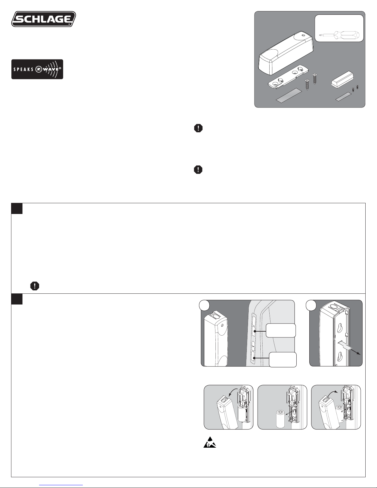
Optional
Installation Tool
1
Prepare the Nexia Bridge for Enrollment. Choose and follow the easiest option for you shown below.
Battery powered Bridge:
• Disconnect Ethernet and power to the Bridge.
• Install a new, high-quality 9-volt battery into the Bridge.
• Move the Bridge to within 6 feet (1.8 meters) of the Sensor. Keep the Bridge in this position during the entire enrollment process.
AC powered Bridge:
• Move the Sensor to the Nexia Bridge for enrollment.
• Keep the Sensor within 6 feet (1.8 meters) of the Nexia Bridge during the entire enrollment process.
For more information, refer to the Nexia Bridge User Guide.
DO NOT plug in Ethernet or power before enrolling!
2
Activate and Enroll the Sensor
a. Press and release the “+” button on the Bridge. The orange LED
will blink slowly to indicate enrollment mode. The Bridge will
remain in enrollment mode for 30 seconds before timeout.
b. Remove the Sensor’s plastic pull tab to activate battery power
and start the Sensor’s enrollment mode. The Sensor’s LED will
blink.
! If the plastic tab is already removed, then remove the
battery for ten (10) seconds and replace the battery (shown,
right) to restart enrollment mode.
c. The orange LED on the Bridge will blink rapidly when enrollment
begins. The Bridge and Sensor LEDs will light solid to indicate
successful enrollment.
! If the Bridge LED never blinks rapidly and enrollment mode
times out (after 30 seconds), then repeat steps a-c.
Orange
LED
+
Button
b.a.
ATTENTION! Electrostatic Sensitive!
Avoid touching the antenna or circuit board when handling the
battery.
3
LIGHTING &
MODULES
CAMERAS
CLIMATE
SECURITY &
SENSORS
CLOSED
Setup Device
New Sensor 3
Sensors Locks
Security & Sensors
New Sensor
Sensor Type Door
Alerts
Alert when opened
Alert when closed
Save Changes Cancel
C
CLOSED
OPEN
Sensors Locks
my sensor
Sensors Locks
my sensor
CLOSED
OPEN
Sensors Locks
my sensor
Sensors Locks
my sensor
Event History
Filter by: Show All
Date Time User Device Event
02/15/2012 12:00 PM New Sensor 4 Tamper Alarm
02/15/2012 11:30 AM New Sensor 4 Closed
02/15/2012 11:30 AM New Sensor 4 Opened
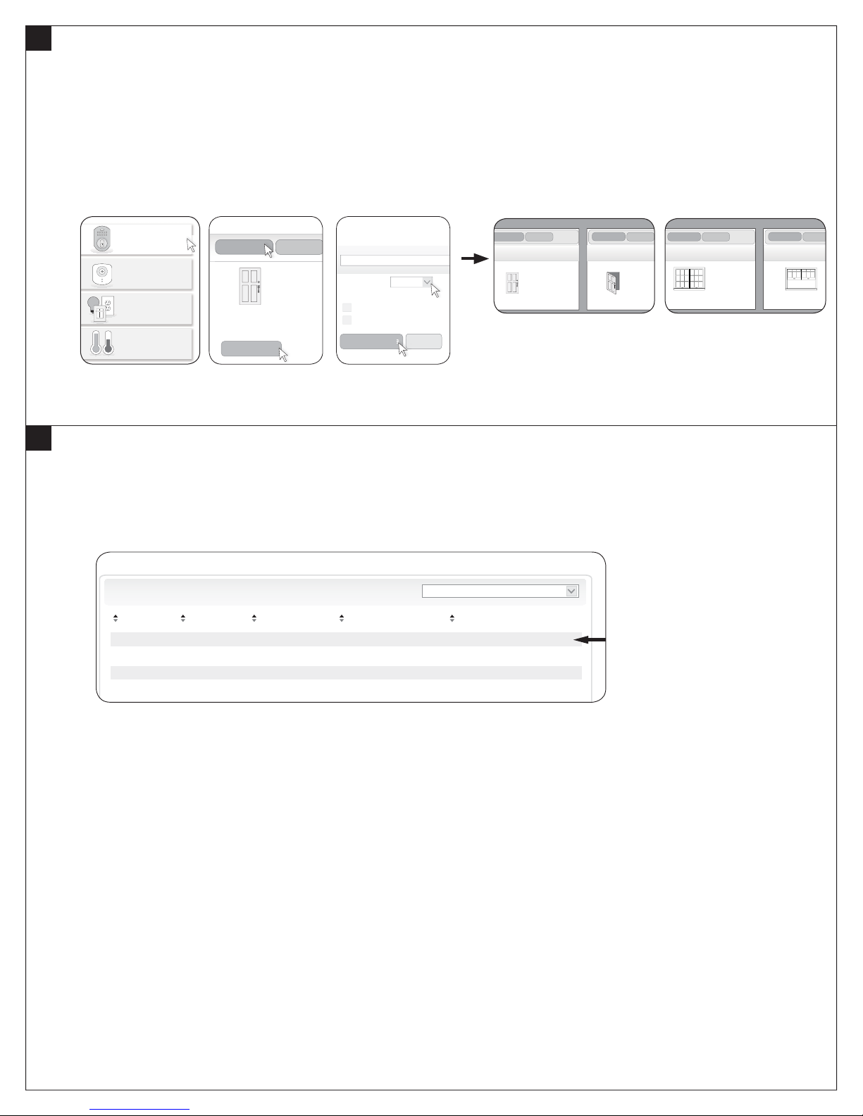
Verify the Door/Window Sensor is added to the Nexia Bridge
! Remove the 9-volt battery from the Nexia Bridge, if installed.
a. Connect the Bridge to AC power and to your router (ethernet).
b. Login to your online Nexia account.
c. Click on “Security & Sensors”, then “Sensors”, then “Setup Device”. To change the icon from door to window (or from window to door), click
“Setup Device” and choose the appropriate “Sensor Type”. (See Figures 1 – 3 below.)
d. Move the magnet close to and away from the Sensor to view the Portal response. Check that the Nexia Portal door or window icon
responds appropriately. (Refer to examples below.)
Note: Browser feedback is not immediate. The online display may take 5 seconds to 1 minute to change. Be sure to allow time for the browser
to refresh.
Figure 1 Figure 2 Figure 3 Door Sensor Window Sensor
4
Test the Tamper Switch (Optional)
a. Press the tab on the top of the Sensor and pull forward to remove the front cover.
b. The Sensor will transmit the tamper condition to the Nexia Bridge.
c. Check that the tamper condition is indicated on the Nexia Portal Event History tab. (Refer to the example below.)
d. Replace the Sensor cover.
5
OR
OR
OR
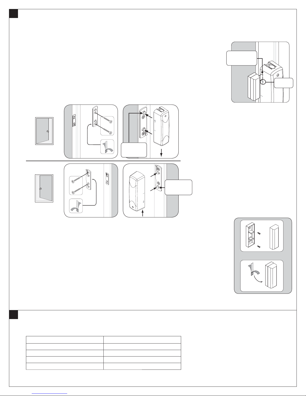
Install the Sensor and Magnet
! The Sensor and Magnet may be installed using either adhesive tape or screws (included).
Follow steps for the preferred method.
! For door applications, determine door handing before installation (see examples
shown below).
Install the Sensor with screws
a. Use the two fl at-head screws (included) to attach the Sensor mounting bracket to the door jamb or
window frame.
b. Attach the Sensor to the mounting bracket, then push down (or up) to secure the Sensor on the
bracket.
OR Install the Sensor with adhesive tape
a. Attach the Sensor mounting bracket to the door jamb or window frame using a strip of double-sided
adhesive tape (included). Note: Extended use of double-sided tape may damage paint or wallboard.
b. Attach the Sensor to the mounting bracket, then push down (or up) to secure the Sensor on the
bracket.
Left hand door
IMPORTANT!
Sensor and magnet must be
aligned as shown
¹⁄₄” (6 mm)
maximum
Arrow
Tabs
point up
Right hand door
Tabs point
down
! The top of the magnet must be within ¹⁄₄” (6 mm) of the arrow on the
Sensor (as shown above).
! Install the magnet no more than ³⁄₄” (19 mm) away from the Sensor for optimal performance.
Install the Magnet with screws
a. Remove the base from the magnet.
b. Use two (2) small screws (included) to attach the base of the magnet to the door or window.
c. Press the magnet onto the base.
OR Install the Magnet with adhesive tape
a. Attach the magnet to the door or window using a strip of double-sided tape (included).
Note: Extended use of double-sided tape may damage paint or wallboard.
6
Sensor Operation
The Sensor detects and sends open/closed position status to the Nexia Portal. The Sensor is not intended to operate as a Z-Wave
repeater.
Activity Sensor LED
Sensor unenrolled Continuous blinking
Enrollment completed Solid light
Tamper Solid light
Open or closed detection Single blink
 Loading...