

Schlage ND Series,ND70,ND73,ND66,ND60,ND72,ND75,ND93,ND95,ND94,ND97 Standard Installation Instructions
P515-167
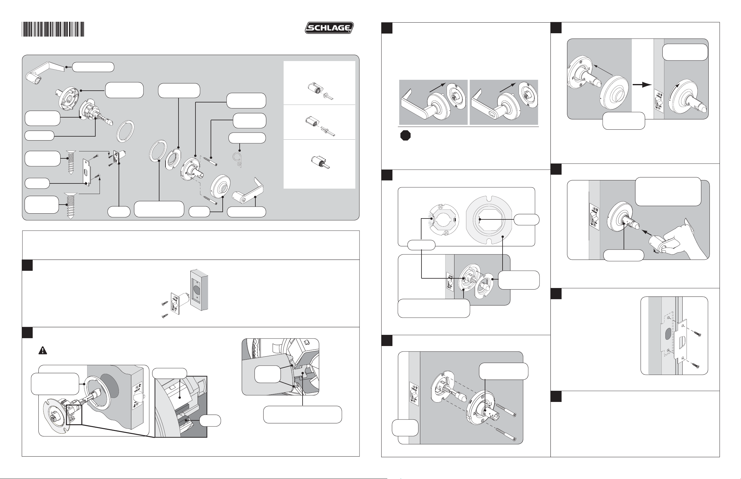
Outside Lever
ND-Series
Standard Installation Instructions
ND53 Function Shown
Cylinder Options
Full Size IC (FSIC)
3
Non-Keyed Outside Levers ONLY:
Install Outside Lever and Springcage
Keyed IC Outside Levers ONLY:
Install Outside Lever and Springcage - DO NOT
install IC cylinder
Non Keyed Keyed IC
6
Install Inside Rose
Rotate rose
until it stops.
Adjustment
Plate
Chassis
Latch
Screws (2)
Strike
Strike
Screws (2)
Outside
Spring Cage
Latch
Optional Spacer
for 1³⁄₈” Door (2)
Anti-Rotation
Plate
Rose
Inside Spring
Cage
Small Format (SFIC)
Mounting
Screws (2)
Pin Wrench
Standard Cylinder
See Keyed Levers/Timing
for installation instructions
Inside Lever
Door Preparation
For door preparation use the template included in the package with the lock. For additional information, refer to the Schlage website:
securitytechnologies.ingersollrand.com
Align dimple
and groove.
IMPORTANT! ALL Keyed Outside Levers:
!
Follow steps at Keyed Levers/Timing
Non-Keyed Levers ONLY, go to step 4
7
4
Install Anti-Rotation Plate
Align the tab with the indent
on the hub.
Ta b
Install Inside Lever
Rotate lever slightly
toward lever catch and
fi rmly push on until lever
catch engages.
Indent
Lever catch
1
Install Latch
The bevel must face toward the door stop.
2
Install Chassis
IF DOOR THICKNESS IS NOT 1³⁄₄”,
SEE “DOOR THICKNESS ADJUSTMENT”.
Optional Spacer
1³⁄₈” (35 mm) thick
door ONLY
Latch prongs fi t between slide and slide clip.
Slide Clip
Slide
Latch
Prongs
IMPORTANT!
Push latch to center of slide
Optional Spacer
³⁄₈” (35 mm) door ONLY.
1
5
Install Inside Spring Cage Assembly
Door
edge
Anti-Rotation
Plate
Lever catch
faces door edge.
8
Install Strike
9
Check Lock Function
If a keyed function does not work properly, see
KEYED LEVERS/TIMING.
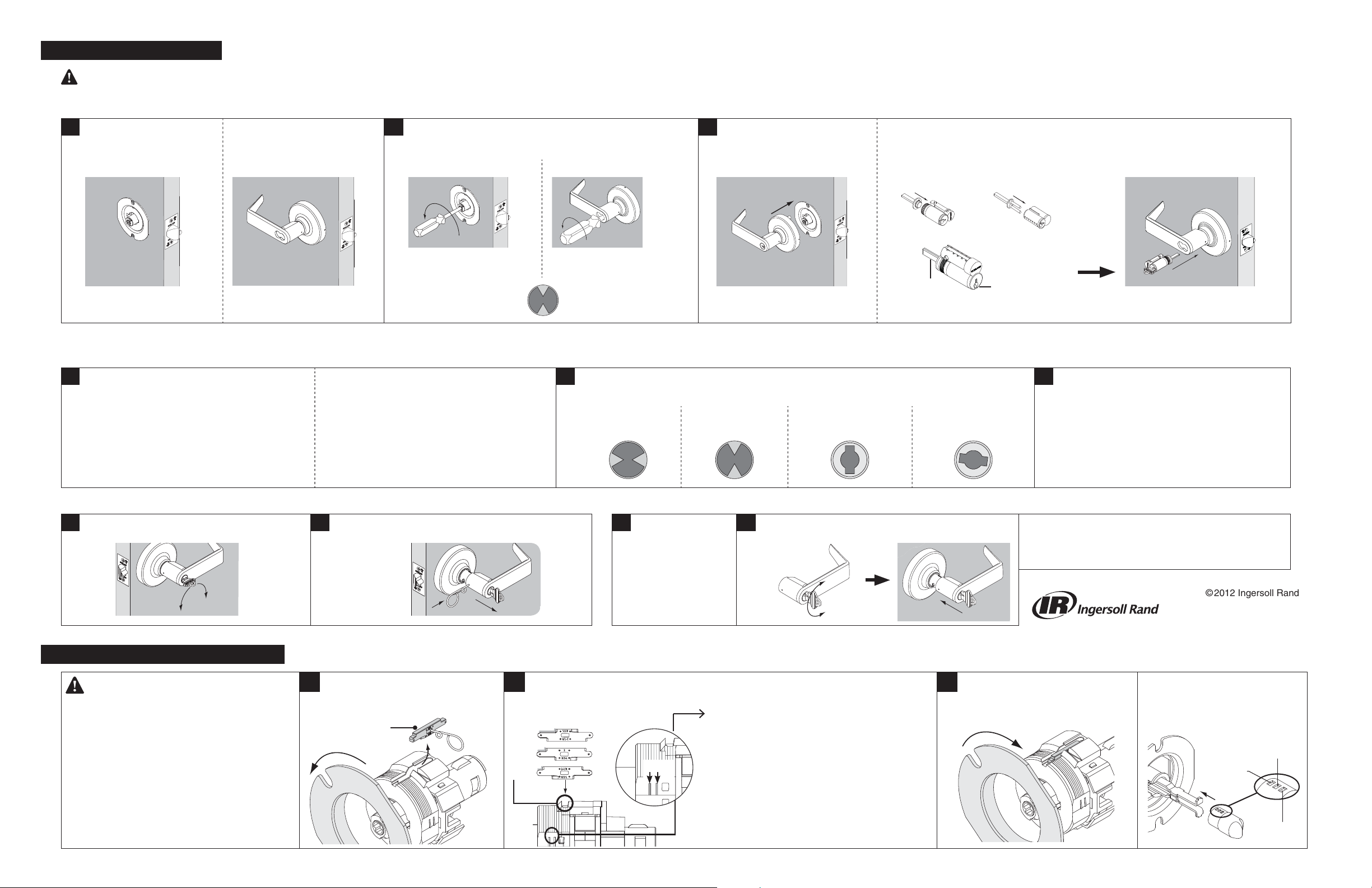
KEYED LEVERS/ TIMING
90°
IMPORTANT: DO NOT insert key in outside cylinder (if applicable) before or during these steps. FAILURE TO PROPERLY TIME THE LOCK WILL RESULT IN IMPROPER FUNCTION, AND CAN CAUSE DAMAGE TO THE LOCK.
ND70 and ND73 ONLY
STANDARD CYLINDER:
a
Install chassis only.
IC CYLINDER:
Install lock except for outside
IC and driver.
b
ND60, ND66, ND72, ND75, ND93, ND94, ND95 and ND97 ONLY
STANDARD CYLINDER:
a
Install lock except for inside lever*
*ND72 ONLY: Install chassis only. Both inside
and outside cams require timing.
IC CYLINDER:
Install lock except for inside IC and driver*
*ND72 ONLY: Install lock except for inside and
outside IC and driver. Both inside and outside
cams require timing.
Rotate key cam counterclockwise until it stops. Then rotate
clockwise to the position as shown below.
STANDARD CYLINDER IC CYLINDER
Rotate key cam clockwise to the correct position as shown below.*
b
*ND72 ONLY: Rquired on inside and outside cams.
Standard Cylinder
STANDARD CYLINDER:
c
Install the outside lever.
Then, continue with Step 4.
IC Cylinder ND66 Standard Cylinder ND66 IC Cylinder
IC CYLINDER:
Insert driver.
Align cylinder tailpiece blade and keyway.
FSIC SFIC
Tailpiece
blade
FSIC shown
Keyway
Turn the key 15° and hold.
Install the cylinder.
Then, continue with Step 4
Follow step C as shown above.
c
Then, continue with Step 4.
Remove a Keyed Lever TROUBLESHOOTING–If levers do not function properly, follow these steps:
To remove a keyed lever, rotate key 90°.
a
Insert pin wrench and push against lever catch.
b
Pull off the lever.
Remove lever as
a
shown at left.
Rotate key 180° and reinstall lever.
b
180°
DOOR THICKNESS ADJUSTMENT
For 1³⁄₄” thick doors, NO ADJUSTMENT
IS REQUIRED.
For 1³⁄₈” thick doors, install the Optional
Spacers (see steps 2 and 4). No further
adjustment is required.
For 1⁵⁄₈”, 2” or 2¹⁄₈” doors, complete the
following steps.
Remove adjustment plate and door
a
thickness insert.
Door thickness
insert
Reinsert door thickness insert with
b
correct dimension visible.
1⁵⁄₈”
2”
2¹⁄₈”
2” 1³⁄₄”
If door thickness insert is missing, use marks
on chassis:
1³⁄₈” Align adjustment plate with 1³⁄₄” mark.
Use optional spacers. (For ND85 rotate additional half
turn CCW.)
1⁵⁄₈” Tighten adjustment plate to bottom, then rotate a
half turn CCW.
1³⁄₄” Align adjustment plate with 1³⁄₄” mark. (For ND85
rotate an additional half turn CCW.)
2” Align adjustment plate with 2” mark.
2¹⁄₈” Align adjustment plate with 2” mark, then rotate an
additional full turn CCW.
CCW = counterclockwise
Reinstall adjustment plate.
c
Tighten until plate contacts door
thickness insert fl at.
For more information call
Technical Support at 877-671-7011.
© 2012 Ingersoll Rand
Printed in U.S.A.
P515-167 Rev. 06/12-e
If applicable, adjust turn button
position.
1³⁄₄" (44 mm)
1³⁄₈" (35 mm)
2" (51 mm)
2¹⁄₈" (54 mm)
1⁵⁄₈" (41 mm)
 Loading...