

Schlage MPC Cobra Series Installation Instructions Manual
Installation Instructions
C
L
LEVER/
STRIKE
3 Di
3 Gi
4 Ji
4 Qi
1 Qi
15/16
DRILL FOR
#12-24
MACHINE
OR OR #12
WOOD
SCREWS
(2 PLACES)
5/32” DEEP
1 Qi ” DEEP
C
L
MPC COBRAMPC COBRA
MANUALLY PROGRAMMABLE CYLINDRICAL
LOCKING SYSTEM
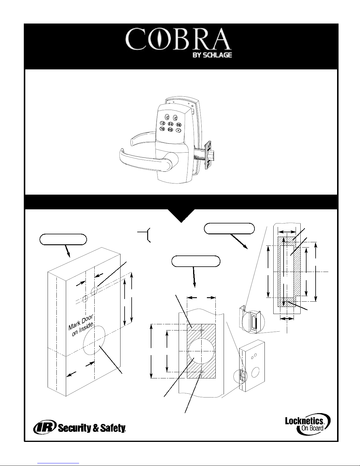
DOOR, LATCH AND FRAME PREPARATION:
11
3 Gi
3 Ji
Ji
BACKSET*
C
L
DOOR EDGE
C
L
LOCK
C
L
LEVER/
STRIKE
DOOR MUST
CORRESPOND
WITH CENTERLINE OF
STRIKE
2 Qr
1 iQ
1 Gi
1” HOLE INTO
2
Qi“ HOLE
2 Qi“ THRU
19/32”THRU
(2 PLACES)
DRILL FOR #6-32 MACHINE
OR
#6 WOOD SCREWS
(2 PLACES)
DOOR PREP
FRAME PREP
LATCH PREP
*BACKSET = 2 Difor OLB
(MEASURED FROM = 2 Drfor SLB & ELB
CENTER OF BEVEL)
Use template or information below to prep
door, latch and frame.
3/16” DEEP
Form 57010 Rev. A 02-22-2002
The MPC Cobra is a battery-pow-
ered manually programmed access
control system. Up to 100 individual
codes can be programmed right at
the keypad. A red and green LED
on the keypad provide visual indica-
tion for programming and access
events. Mechanical key override is
possible when a 7-pin small-format
interchangeable core (not included)
is installed in place of the cylinder
plug, which comes standard. Either
the plug or the IC core must be
installed for the lock to operate. When the
cylinder is removed (using the cylinder con-
trol key) the lock will unlock. Manual key
override should only be necessary if the low
battery output indications have been ignored.
(See Battery Information on page 3). The
design allows for mounting on doors from 1-
1/2” to 2” thick. The retractor design allows
easy adjustment for door thickness by rota-
tion. A shim is available to mount the lock to
a 1-3/8” door. An exterior gasket (EG option)
is available for application to exterior sides of
doors.
Page 1 of 2Page 4 of 4
SEE PAGE 4 FOR INFORMATION REGARDING
THE USE OF MECHANICAL KEY OVERRIDE
AND INSTALLATION STEPS FOR 7-PINSMALL
FORMAT IC CORE.
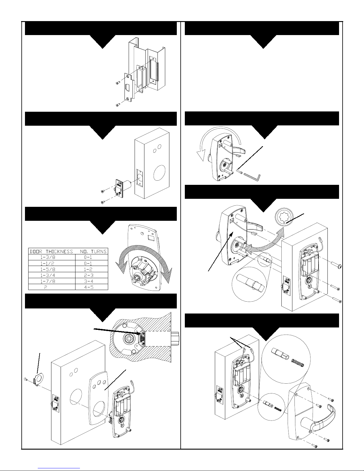
Apply LoktiteTM242 or
equivalent to threads
Dot must face
down.
Apply Exterior
Gasket (EG option)
to this surface if
required.
Screw retractor all the way in and
unscrew it the correct number of
turns according to door thickness:
Make sure latch
tabs engage the
retractor as shown:
Install latch guard.
Plug in wiring harness
Shim plate only required
for 1-3/8” doors
INSTALL STRIKE & STRIKE BOX:
22
INSTALL LATCH:
33
REVERSE LEVERS (IF REQUIRED):
77
SET RETRACTOR DEPTH:
44
INSTALL INSIDE BASEPLATE ASSEMBLY:
55
INSTALL CYLINDER (RECOMMENDED):
66
INSTALL OUTSIDE ESCUTCHEON/SPINDLE:
88
INSTALL INSIDE ESCUTCHEON/SPINDLE:
99
Page 2 of 2 Page 3 of 4
 Loading...