

Schlage GF3000 Installation Instructions Manual
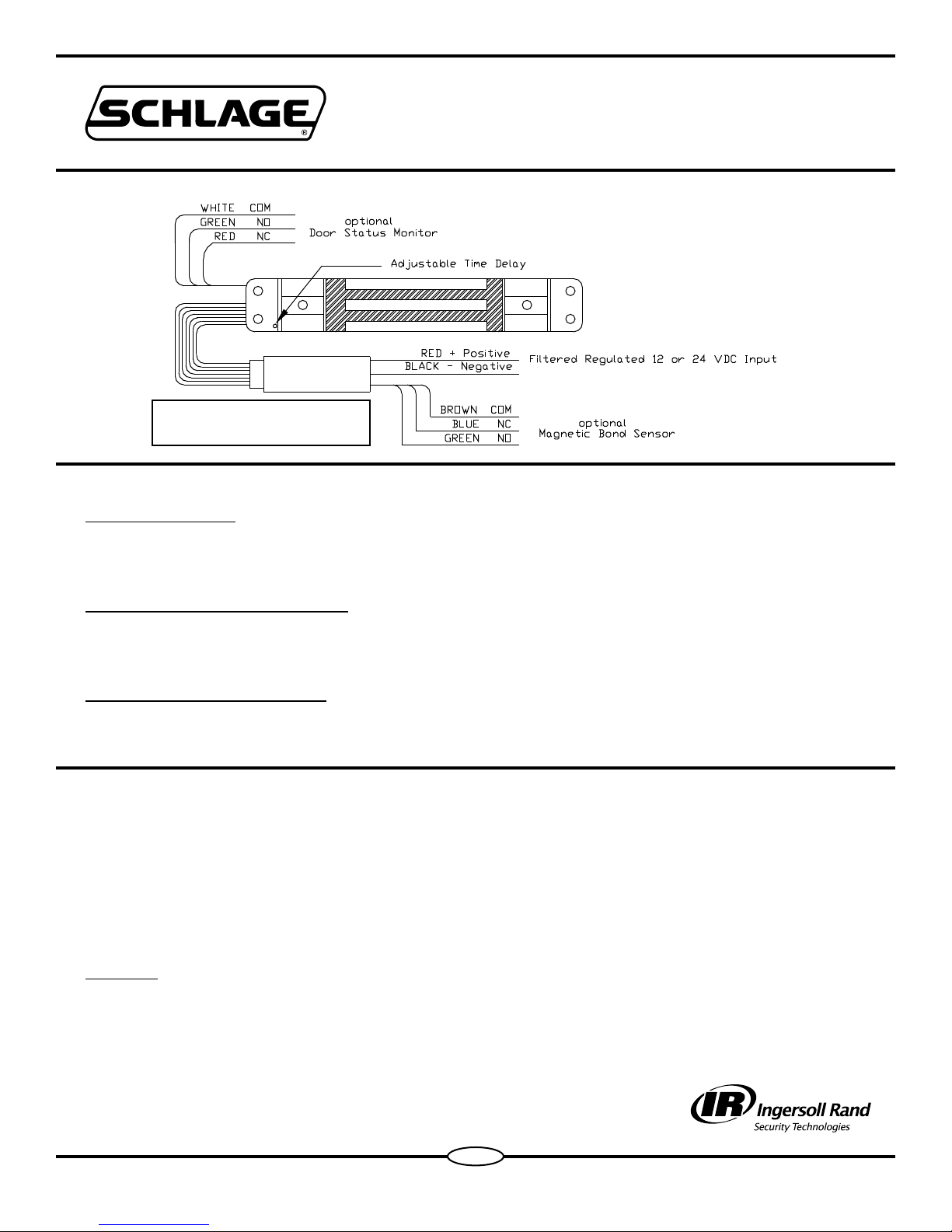
WIRING
IMPORTANT: DO NOT CUT
YELLOW WIRE.
STANDARD FEATURES
Operating Voltage
The GF3000 will operate only on filtered, regulated 12 or 24 volts DC.
Automatic voltage selection circuitry is standard.
GF3000 CONTROL MODULE
INSTALLATION INSTRUCTIONS
Automatic Relock Switch (ARS)
A built-in relock switch requires the door to be in the closed position before the magnet
can be energized.
Adjustable Time Delay (ATD)
ATD provides a time delay for relock that is adjustable from 1 to 30 seconds.
The unit has been preset at the factory for a 3 second relock delay.
ADJUSTING TIME DELAY
Power must be applied for this procedure.
1.) Refer to the above “Electrical Wiring” figure and note location of ATD arrow.
2.) Remove 5/64” hex head screw to allow access to a recessed momentary
push-button switch.
3.) Using the hex (Allen) wrench, depress and release the recessed switch one time
for each second of delay required.
Example: To set ATD to 5 seconds depress the recessed switch 5 times.
NOTE: If a mistake is made, wait 10 seconds then repeat Step #3.
4.) Reinstall hex head screw, after setting desired relock delay.
Form 30501-A 07-2007
1
OPTIONAL MONITORING OUTPUTS
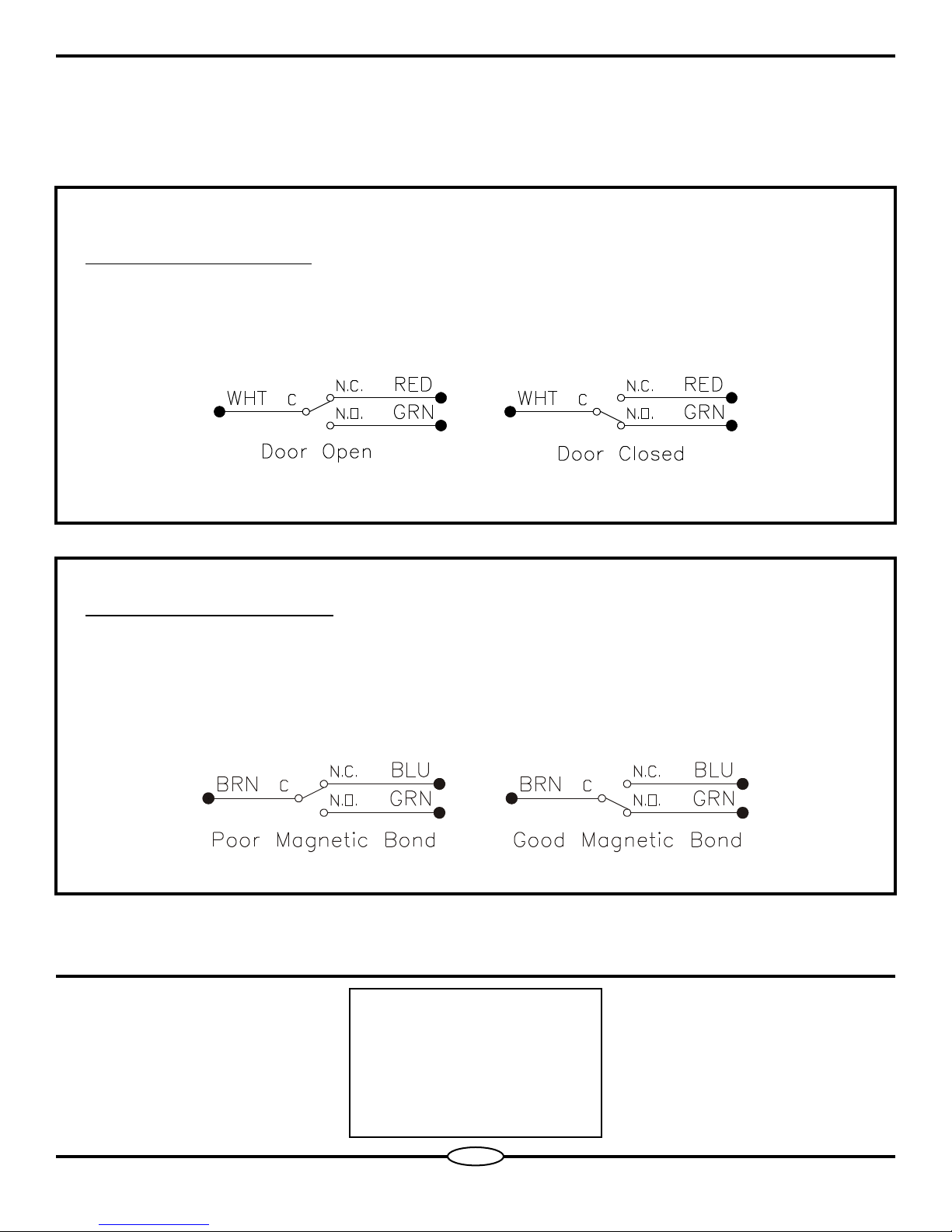
Door Status Monitor (DSM)
The optional DSM provides a dry set of contacts for monitoring “door open” or
“door closed” conditions.
Magnetic Bond Sensor (MBS)
The optional MBS provides a dry set of contacts for monitoring “door locked”
or “door unlocked” conditions. The MBS measures the magnetic holding
force between the armature and the magnetic coil. Poor magnetic bond is the
result of low voltage, foreign material between the surfaces of the magnetic
coil and armature, or improper alignment of magnet and armature.
Schlage Lock Company
575 Birch Street
Forestville, CT 06010
technical support: 866-322-1237
fax: 860-584-2136
web: http://www.irsupport.net
Form 30501-A 07-2007
2
 Loading...