

Schlage FingerKey User Manual
FingerKey
Terminal User’s Guide

Table of Contents
Using the HandNet Lite/FingerKey Product CD .........................vi
Software on this CD ....................................................................................................vi
Installing HandNet Lite ................................................................................................ vi
Installing the FingerKey Update Utility .........................................................................vi
Installing the FingerKey Backup/Restore Utility .......................................................... vii
Documentation on this CD .........................................................................................vii
Introduction ....................................................................................3
What the FingerKey Does ............................................................................................3
How FingerKeys Recognize User Fingerprints .............................................................3
Networking Readers .....................................................................................................3
FingerKey Features ......................................................................................................4
Setup Overview ............................................................................................................4
Installing the FingerKey ................................................................5
Before You Begin .............................................................................................................5
Tools You Need for the Installation................................................................................5
What You Need in Addition to the Reader ....................................................................5
Protecting the Reader during the Installation ...............................................................5
Choosing the Location for the Reader .............................................................................6
Fastening the Reader to the Wall ....................................................................................7
Protecting the Reader from Dust and Debris ...............................................................7
Mount All Readers at the Same Height ........................................................................7
Mounting the Back Panel on the Wall ...........................................................................7
Wiring the Reader ...........................................................................................................9
Disclaimer .....................................................................................................................9
Wiring Overview ...........................................................................................................9
Connections on the Back of the Reader .......................................................................9
Setting DIP Switches ..................................................................................................10
Connecting the Reader to the Access Control Panel, to an External Card Reader, and to
Other Readers ............................................................................................................11
Connecting Power Input .............................................................................................12
Establishing a Solid Ground Connection ....................................................................12
Networking Readers ......................................................................................................13
Networking Caution ....................................................................................................13
Designating a Master Reader .....................................................................................13
Making Sure DIP Switches are Set UP Correctly .......................................................13
Network Wiring ...........................................................................................................13
Secure Setup Guidelines ............................................................14
Secure Setup Overview .................................................................................................14
Designing a User ID Numbering System.......................................................................15
ii

HandKey II Manual
If a Card Reader Identifies Users ...............................................................................15
If Users Must Type Their ID Numbers on the Reader Keypad ....................................15
What Authority Levels Are For ....................................................................................16
What Each Authority Level Lets You Access ..............................................................16
Why Setting Authority Levels Is Critical ......................................................................16
Entering Users in the Appropriate Order ....................................................................16
Setting Authority Levels for Supervisory Staff ...............................................................16
Changing a User’s Authority Level .............................................................................17
Enrolling and Maintaining Users ................................................19
Preparing to Enroll Users ..............................................................................................19
Eliminating Potential User Concerns ..........................................................................20
Correct Finger Placement ..........................................................................................20
Choosing a Finger ......................................................................................................20
Teaching Users How to Use Readers ...........................................................................20
Enrolling Users ..............................................................................................................21
For DX-2200 Readers (iCLASS) ................................................................................22
Maintaining Users ..........................................................................................................23
If Many Users Are Having Access Problems ..............................................................24
If a Particular User Is Having Access Problems .........................................................24
If Users Have Trouble Gaining Access ..........................................................................24
Ongoing Reader Maintenance ....................................................25
Cleaning Readers ..........................................................................................................25
Why Readers Need to Be Cleaned ............................................................................25
How to Clean a Reader ..............................................................................................25
How Often Readers Should Be Cleaned ....................................................................25
Reset Options .............................................................................................................26
Erasing Only the Users .............................................................................................26
Erasing the Setup or the Setup & Users & Passwords ...............................................26
Clearing or Resetting the Reader ..................................................................................26
System Requirements ................................................................................................28
Making Sure You Have the .NET Framework .............................................................28
Installing the .NET Framework ...................................................................................28
Upgrading the Reader’s Firmware .................................................................................28
Installing the FingerKey Update Utility ........................................................................29
Upgrading the FingerKey or Sensor Firmware ...........................................................29
Establishing Communication Between the Reader and the Update Utility .................30
Updating the FingerKey’s Application Firmware .........................................................31
Resetting the FingerKey .............................................................................................31
Programming the FingerKey ......................................................32
Which Settings You Should Change in the Reader .......................................................32
Menus in the Reader ..................................................................................................32
Summary of menu options .........................................................................................33
Getting to the Menus in the Reader ...........................................................................34
iii

Navigating the Menus .................................................................................................35
What You Can See with This Menu ............................................................................36
How to Get to This Menu ............................................................................................36
Network Status ...........................................................................................................36
Service Menu ................................................................................................................36
Setup Menu ...................................................................................................................37
What You Can Change with This Menu ......................................................................37
Getting to This Menu ..................................................................................................37
Indicating Whether the Reader is a Master ................................................................38
Setting the Reader’s Address .....................................................................................38
Setting the Type of Network Connection ....................................................................39
Serial Connection .......................................................................................................39
TCP/IP Connection .....................................................................................................39
Setting Up a Duress Indicator or Alternate Finger .....................................................40
When an alternate or duress finger is placed on the reader ......................................40
Controlling the Beeper and LEDs ...............................................................................41
Setting the ID Length ..................................................................................................41
Setting the Language for the Reader’s Display ..........................................................41
Increasing the Maximum Number of Users Readers Can Accept ..............................42
Enabling the Reader to Communicate with a Host Computer by Ethernet ................42
Management Menu .......................................................................................................43
What You Can Do with This Menu ..............................................................................43
Getting to This Menu ..................................................................................................43
Listing Users ...............................................................................................................43
Getting Users from Other Readers .............................................................................43
Sending User Information to Other Readers ..............................................................44
Checking to See if a Particular Networked Reader is Connected ..............................44
Enrollment Menu ...........................................................................................................45
What You Can Change with This Menu ......................................................................45
Getting to This Menu ..................................................................................................45
Adding Users ..............................................................................................................45
Adding Users on a DX-2200 (iCLASS) .......................................................................45
Choosing Where to enter the User’s ID ......................................................................46
Completing the Enrollment Process ...........................................................................46
Removing Users .........................................................................................................46
What You Can Change with This Menu ......................................................................47
Getting to This Menu ..................................................................................................47
Customizing a User’s Settings ....................................................................................47
Which reader menus a user may access ...................................................................48
Setting Supervisory Passwords First ..........................................................................48
Enrolling Users Who Don’t Need Finger Recognition to Gain Access .......................49
How Closely the User’s Fingerprint Must Match the Stored Template .......................50
Figuring Out What to Set The Reject Level To ............................................................50
Controlling How Sensitive the Reader is When Verifying Fingerprints and How Many Tries
a User Gets ................................................................................................................51
Setting Passwords for the Reader Menus ..................................................................51
iv

HandKey II Manual
Erasing All Users from the Reader .............................................................................52
Controlling How the Secondary Finger is Used for Individual Users ..........................52
Setting Input and Output Card Formats .....................................................................53
Interpreting the Format Detail Below ..........................................................................53
Available Card Formats ..............................................................................................54
Assigning the Facility Code ........................................................................................55
Setting the Site ID ......................................................................................................55
Set Company ID .........................................................................................................55
Set Issue Code ...........................................................................................................56
Set Expiration .............................................................................................................56
Setting Input Formats .................................................................................................57
Setting Output Formats ..............................................................................................58
Setting the Keypad Format .........................................................................................58
Modifying Output for Specific Reader Situations ........................................................58
Resetting the Reader .................................................................................................59
Configuring the Reader for Smart/HID iCLASS Cards ...............................................59
Setting a New Key in the Reader ...............................................................................60
Determining Whether Keys Get Automatically Updated on Cards .............................60
Converting a Reader Key for HandNet Lite ................................................................61
Setting the Old Key in the Reader ..............................................................................62
New Cards Automatically are Handled .......................................................................62
Controlling If/When Card Keys are Automatically Updated ........................................62
Manually Updating a Key on a Card ...........................................................................63
Controlling Fingerprint Template Compression ..........................................................63
Erasing Cards .............................................................................................................63
Listing Info about the Card User .................................................................................64
Appendices ..................................................................................65
FingerKey Specifications ............................................................65
Index .............................................................................................67
v

Using the HandNet Lite/FingerKey Product CD
Using the HandNet Lite/FingerKey Product CD
Software on
this CD
Installing
HandNet Lite
HandNet Lite: This program manages your users (and their biometric finger templates),
and lets you set up and maintain your FingerKey network.
FingerKey Update: This utility is used to update firmware in your FingerKey reader.
FingerKey Backup/Restore: This is used to backup or restore a single FingerKey,
including setup information and the user database.
Important: HandNet Lite requires Windows 2000 SP4 or Windows XP SP1 to install.
Before installing, you should also install any critical Windows Updates. To do this, on your
Start menu, pick Programs, and choose Windows Update.
HandNet Lite requires the .NET 1.1 framework to work. The installer asks you to install
.NET 1.1. Always click Yes unless you are sure you already have it.
1. Using My Computer or Windows Explorer, find the CD Drive and double-click the CD
icon.
2. Double-click the HandNet_Lite folder.
3. Double-click Setup.exe. You may wish to read the Release Notes files first.
4. Answer the installation questions; we recommend accepting the default settings on
each screen.
Some of the delays during the installation can seem long; please be patient as the
Microsoft dotNet framework and MSDE SQL Server are installed.
5. After the installation is done, you’ll be asked to restart (reboot) your computer. You
must do this before you can start HandNet Lite.
Installing the
FingerKey
Update Utility
vi
If you had an earlier version of this utility: Go to your Control Panels, choose Add/
Remove Programs, and remove any earlier version of this program before installing.
1. Using My Computer or Windows Explorer, find the CD and double-click the CD icon.
2. Double-click the FK-Update folder.
3. Double-click Setup.exe.
4. Follow the prompts on the screens.
The firmware on the FingerKey (v. 1.10) is on the CD in the FK-Firmware folder.

HandKey II Manual
Installing the
FingerKey
Backup/
Restore Utility
Documentation
on this CD
If you had an earlier version of this utility: Go to your Control Panels, choose Add/
Remove Programs, and remove any earlier version of this program before installing.
1. Using My Computer or Windows Explorer, find the CD Drive and double-click the CD icon.
2. Double-click the FK-BackupRestore folder.
3. Double-click Setup.exe file.
4. Follow the prompts on the screens.
• FingerKey Installation and Operation Guide
• HandNet Lite Read Me
• HandNet Lite Release Notes
• HandNet Lite User Guide
vii

Introduction
What the
FingerKey
Does
How
FingerKeys
Recognize User
Fingerprints
The FingerKey stores a mathematical representation of the fingerprint and uses this
numerical “picture” to confirm user identity. When the FingerKey recognizes a user’s
fingerprint, it notifies an access control panel, which in turn sends a signal that unlocks
the appropriate door. Depending on the type of access control panel, the panel may also
control other systems like alarms,
lights, and closed circuit cameras.
The FingerKey communicates
with access control panels using
Wiegand or Clock/Data.
The FingerKey initially is configured
to store up to 50 users. You can
purchase memory upgrades to
enable it to store additional users.
FingerKeys shine a light on the
finger to capture a mathematical
“image” of finger contours based on
how the light reflects back. This numerical representation of the fingerprint, which we call
a template, identifies details like bifurcations, ridge endings, and crossovers. The reader
stores this template and associates it with the user’s ID number.
When a user wants to gain access, he/she enters an ID number (either by typing it in or
by using a card reader). The reader asks the user to place a finger on the reader, and the
reader then checks to see if the fingerprint matches the fingerprint template stored for
that user. The reader notifies the access control panel about whether there was a match,
and the access control panel then grants or denies access and takes other action as
appropriate.
Networking
Readers
FingerKey readers can be used independently, or they can be networked with other
FingerKey readers. If you network the readers, you can enroll users in one reader and
then transfer those users to the other readers; this lets you enroll each user once instead
of having to manually enroll each user at each reader.
3

Introduction
FingerKey
Features
The LCD display
shows messages and
programming menus.
The keypad allows
users to enter ID
numbers. It also
allows for reader
set-up.
Guides help users
place their fingers
correctly on the
sensor window.
Setup Overview
Red/green/amber
verifcation LEDs
quickly show users if
the finger was
recognized, and flash
other warning and
status signals.
1. If you haven’t done so already, get the appropriate access control panel and
electrified door hardware (lock, door position switch, request to exit, etc.).
2. Install the reader on the wall by the door; see page 6.
3. Wire the reader and connect it to your access control panel; see page 9
4. Design an ID numbering system; see page 15.
A properly designed ID numbering system makes the reader faster and easier to use.
5. Add/enroll your supervisory staff.
This includes users who are authorized to program the reader, users who access
the reader through software, and users who will enroll new users to the reader. The
process for enrolling these users is the same as for enrolling other users; see page 21.
6. Set authority levels for your supervisory staff; see page 16.
This makes sure that these users have access to the options in the reader that they
need, and it also prevents other users from being able to inappropriately access the
reader menu options.
7. Customize settings in the reader as needed.
Use the programming menus in the reader; see page 33.
8. Enroll the users who should have access through the door associated with the
reader; see page 21.
An internal beeper provides
audible feedback.
The internal card
reader provides for
convenient ID entry.
Figure 2-1: Finger Key Features
4

Installing the FingerKey
Before You Begin
Tools You
Need for the
Installation
What You Need
in Addition to
the Reader
Protecting the
Reader during
the Installation
To install the reader, you need:
• a measuring tape
• a torx screwdriver
• wiring tools.
In addition to the FingerKey, you need:
• Electrified door hardware: Electronic lock, door position switch, request to exit, etc.
• Access control-panel: The reader can’t communicate directly with a lock; it must
communicate to an access control panel.
Protect the reader from the dust and debris generated during the wall plate installation
process.
5

Installing the FingerKey
!
Choosing the Location for the Reader
Before you begin installation, check the site blueprints, riser diagrams, and specifications
for important information about reader location. Look for any existing wall preparations
and wiring that other contractors may have installed for the reader.
The reader’s sensor window may be from 40–48 inches (102–122 cm) from the floor. For
best performance, we recommend 48 inches. This makes reading the display, pushing
buttons, and placing fingers comfortable for most people. The reader should be out of the
path of traffic. It should be close to the door but not behind it. Don’t put the reader where
users must cross the swing path of the door.
NOTE
The reader must not be exposed to airborne dust, direct sunlight, water, or chemicals.
40 - 48 in
(102 - 122 cm.)
Figure 3-1: Reader Placement Rules
6

Fastening the Reader to the Wall
HandKey II Manual
Protecting
the Reader
from Dust and
Debris
Mount All
Readers at the
Same Height
Mounting the
Back Panel on
the Wall
At all times, protect the reader from excessive airborne dust and debris. This is
particularly important during the installation process. For example, if you need to cut a
hole in the sheetrock for the electrical box, don’t place an unwrapped reader on the floor
under where you are cutting; the dust would get inside the reader and affect its future use.
Instead, keep the reader in its packaging until you’re actually ready to fasten it to the wall.
Protect the reader, just as you would any other sensitive equipment.
All readers in your facility should be mounted at the same height.
1. Have a double electrical box (double gang box) installed in or on the wall where you
want to install the reader. The top of the box should be between 40 and 48 inches
(102 to 122 cm) from the floor.
2. Run the wiring for the reader to this box, following local electrical code.
• This includes the wiring from your access control panel, the power for the reader,
3. Run the wiring through the black gasket on the mounting plate, and then screw the
reader mounting plate to the electrical box.
• The two tabs on the mounting plate go on the top.
• Use the screws provided with the installation kit; screws with larger heads could
and the network wiring if the readers are networked.
keep the reader from seating or closing properly.
7
Installing the FingerKey
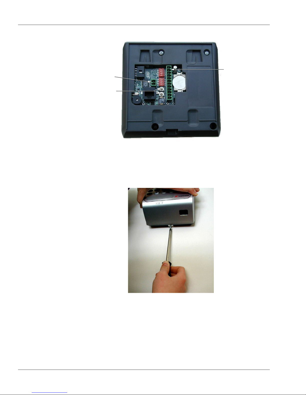
4. Connect the wiring to the reader.
Terminals 1-12 for
Power Connection
reader wiring
connections
Make sure the wire
bundles don’t press
against the rest or
cold boot switches.
• Wiring instructions begin on page 9.
• Make sure you position the wire bundles so they don’t accidentally press the
reset and cold boot buttons when you close the reader. It would cause problems if
the wires kept these buttons pressed when the reader was closed.
5. Hook the top of the reader on to the clips on the mounting plate, push the bottom of
the reader in, and then insert the torx screw that holds the bottom of the reader to the
mounting plate.
• In cold weather: Remember that all plastics are brittle when cold. If, for example,
you’ve left the reader in your truck overnight on a cold winter night, you should let
the reader warm up to room temperature before installing it. (If you don’t, and if
you overtighten the torx screw, you could crack the plastic around the hole.)
8
Wiring the Reader
Always follow any electrical codes for your area.
HandKey II Manual
Disclaimer
Wiring
Overview
Connections
on the Back of
the Reader
Schlage Biometrics is not responsible for readers damaged by improper wiring.
Wiring the reader involves:
• setting the reader’s dip switches for your wiring configuration; see page 10.
• connecting the wires for the access control panel and for other inputs and outputs; see
page11.
• connecting power input; see page 12.
• establishing a solid ground connection; see page 12.
• connecting network wiring; see page 13.
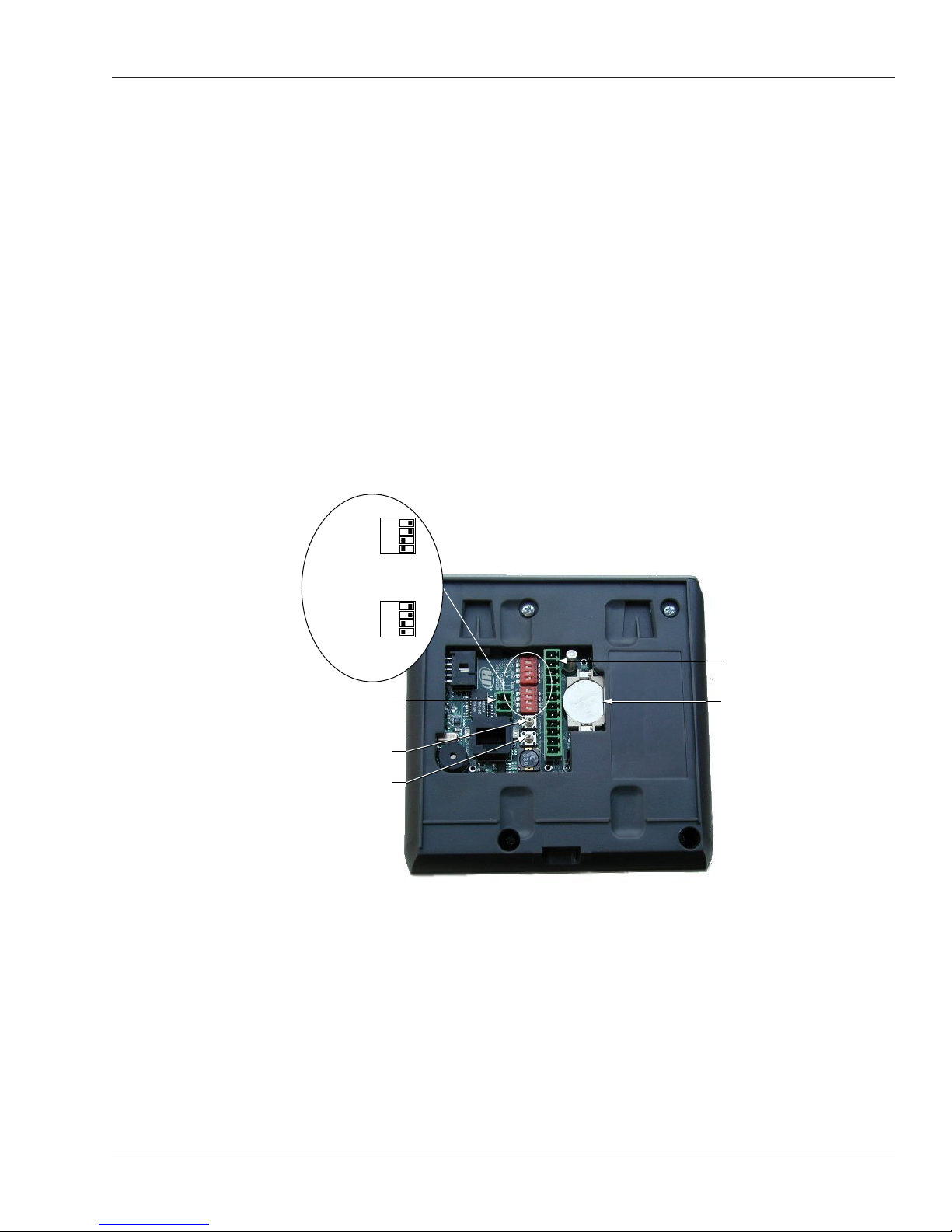
DIP
switch 1
DIP
switch 2
Power supply
connection
1 2 3 4
OFF
1 2 3 4
OFF
ON
ON
Terminals 1-12 for reader
wiring connections
Lithium battery
Coldboot switch
Reset switch
9

Installing the FingerKey
!
Setting DIP
Switches
Controlling how
readers are
networked
Identifying the
type of access
control panel
If you change DIP
switch settings
NOTE
If you change DIP switch settings after the reader has power connected, you must reset
the reader before the change is recognized.
1. Switch 1 controls how readers are networked to each other.
• To network readers (RS-485 wiring): DIP switches 1 and 2 must be on, and DIP
switches 3 and 4 must be off. You will always use this configuration for networking
two or more readers. Set Host Connection in the reader setup must match your
setting here; see Setting the Type of Network Connection on page 39.
• To use the RS-232 cable to connect to our backup utility, to upgrade the reader’s
firmware, or to connect a single reader to a computer host: DIP switches 3 and
4 must be on, and DIP switches 1 and 2 should be off. You’ll only use RS-232 for
updating the reader’s firmware and for using our backup utility. For either of these
purposes, you must set the DIP switch to the appropriate position, but you don’t
need to change Set Host Connection. If you have your readers networked and
have to change the DIP switches to make a backup or to upgrade the firmware,
make sure you put the DIP switches back and reset the reader when you are
done.
• If the reader isn’t networked: It doesn’t matter how switch 1 is set.
2. Switch 2 identifies the type of access control panel connection.
• To connect to a panel via Wiegand/Magstripe: DIP switches 1 and 2 must be on,
and DIP switches 3 and 4 should be off.
• To connect to future Schlage Biometrics products by RS-485 wiring: This is
only for future Schlage Biometrics products. There are no currently available
solutions that use this option. If Schlage Biometrics offers a solution using this
configuration in the future, DIP switches 3 and 4 must be on, and DIP switches 1
and 2 should be off.
3. If you change any DIP switches on a reader that is already connected, you must
reset the reader for the changes to take effect. To reset the reader, you can either
disconnect the power and then apply power again, or you can press the Reset button.
10

HandKey II Manual
Connecting the
Reader to the
Access Control
Panel, to an
External Card
Reader, and to
Other Readers
For each type of connection that you need, connect the corresponding wiring to the
appropriate pins on the terminal connector block.
Table 3-1: Terminal Block Connections
Terminal Connection Notes
1 Card Reader: Wiegand D0 or
Magnetic Stripe Data Input
2 Card Reader: Wiegand D1 or
Magstripe Clock Input
3 Access Control Panel: Wiegand D0,
Magstripe Data Output, or some
other type through RS-485 wiring
4 Ground
5 Access Control Panel: Wiegand D1,
Magstripe clock output
6 Tamper switch output Use this terminal to connect to a
7 External bell input These terminals let you connect output
8 LED red input
9 LED green input
10 Reader/host network Tx: RS-485
wiring or RS-232 wiring
11 Ground
12 Reader/host network Rx: RS-485
wiring or RS-232 wiring
Use these terminals to connect to an
external card reader to supply user IDs
instead of having users enter their IDs
using the reader keypad.
(These terminals aren’t needed if your
reader has a built-in card-reader.)
Use these terminals to connect to an
access control panel.
tamper alarm. A signal goes through
this connection if the reader is tipped,
indicating that someone may be
tampering with the reader.
wires from your access control panel
so your access control panel can
control the bell (beeper) and red/green/
amber LED’s on the reader. For input
here to make a difference, the Beeper/
LED settings on the Setup menu must
be set to respond to external input; see
page 41.
Use these terminals to network with
other FingerKey readers through either
RS-485 wiring or RS-232 wiring. (RS232 is only used to connect a single
reader to a host computer; usually you
will use RS-485.)
11

Installing the FingerKey
!
Connecting
Power Input
Establishing a
Solid Ground
Connection
NOTE
The reader requires 12 volts DC (1000 mA). Connect power to the 2-pin terminal P2.
Table 3-2: Power Supply Connections
Pin Connection
1 Positive
2 Common (Ground)
All readers should have a solid, reliable, earth ground connection. This protects internal
circuit boards from electrostatic discharge and from external signal line transients
(power spikes). A qualified electrician familiar with electrical code and wiring/grounding
techniques should identify the earth ground source.
Earth Ground Connnections connect earth ground securely to the wall mount plate.
Pin 2: Common
Pin 1: Positive
12

Networking Readers
If readers are connected by RS-485, you can connect up to 32 readers to each other.
This allows one reader to serve as a master; it can get users from other readers and send
new users back to them; this lets you enroll a user on one reader and then give that user
access at all of them. See Getting Users from Other Readers starting on page 43.
HandKey II Manual
Networking
Caution
Designating a
Master Reader
Making Sure
DIP Switches
are Set UP
Correctly
Network Wiring
Unless you have the appropriate networking knowledge, we don’t recommend trying to
set up a reader network on your own. We train our dealers to set up reader networks
correctly; we recommend using their services if you are networking readers.
If you network a group of readers to each other and they are not managed by some
software, then you must designate one of the readers as a master, and the rest must be
set up as remote readers; that is, they can’t be designated as master readers.
If your readers are managed by some computer software, the software is the master, so
no readers would be designated as a master
See Indicating Whether the Reader is a Master on page 38 for help changing this setting.
Make sure that DIP switch 1 is set to reflect the type of wiring you use; see Controlling
how readers are networked on page 10.
To create a RS-485 network, use a single twisted pair of wires (plus a ground). For each
reader, connect pin 10 (Tx +/-) on the terminal block to pin 10 on the next reader, connect
pin 11 (ground) to pin 11, and connect pin 12 (Rx +/-) to pin 12. You can connect up to 32
readers. You must use a daisy-chain; a star configuration will NOT work correctly.
For a RS-485 network, at 9600 baud, the maximum total line length for the network is
4000 feet. Use Belden cable 82723 or the equivalent (minimum 22 gage).
For a RS-232 network (which can only connect a single reader to a host computer), the
maximum line length is 50 feet.
13

Secure Setup Guidelines
Secure Setup Overview
1. Design an ID numbering system; see page 15.
A properly designed ID numbering system makes the reader faster and easier to use.
2. Add/Enroll your supervisory staff.
This includes users who are authorized to program the reader, users who monitor
the reader network, and users who will add new users to the reader. The process for
adding these users is the same as for adding other users; see page 21.
3. In the reader, set authority levels for your supervisory staff; see page 16.
This makes sure these users have access to the options in the reader that they need,
and it also prevents other users from being able to inappropriately access the reader
menu options. This step is critical in preventing unauthorized people from getting
around your security system.
4. Customize settings in the reader as needed; see Programming the FingerKey starting
on page 32.
This step is listed here because you would normally complete your reader setup
before adding users, but you can actually change the settings in the reader at any
time.
5. Teach your users how to use the reader and then add/enroll them in the reader.
See page 20 for more on teaching users how to use the reader; see page 21 for details
on enrolling them in the reader.
14

Designing a User ID Numbering System
HandKey II Manual
If a Card
Reader
Identifies Users
If Users Must
Type Their ID
Numbers on
the Reader
Keypad
You don’t need to design an ID numbering system if you use a card reader to supply the
ID number. The card provides all ID information.
User ID numbers tell the reader which user is trying to gain access.
A well-designed ID number system makes it quicker for you to decide which ID to assign
to a new user, and it makes ID entry faster at the reader through the use of the Set ID
Length command (see page 41).
Follow these guidelines when designing an ID numbering system:
• Each user must have a unique ID number; the reader won’t accept two people with the
same ID. (If you enroll people using the last four digits of their phone numbers or social
security numbers, you may get duplicate numbers.)
• ID numbers may begin with 0 (zero). For example, the reader regards the ID 05 as
different from the ID 5.
• ID numbers can be up to 15 digits long when entered at the reader keypad, but shorter
numbers are easier to remember and easier to enter. (The reader gives you about 10
seconds to enter an ID number.) In most contexts, 4-digit numbers provide adequate
security and are easy to remember and enter.
• Make all ID numbers the same length. This lets you use the Set ID Length command.
If you don’t use the Set ID Length command, users must enter their ID and then press
the enter key; if you use the Set ID Length command, users only have to enter the
ID without needing to press enter; the reader automatically continues as soon as the
appropriate number of digits are entered; see page 41 for more about this command.
15

Secure Setup Guidelines
Setting Authority Levels for Supervisory Staff
What Authority
Levels Are For
What Each
Authority
Level Lets You
Access
Why Setting
Authority
Levels Is
Critical
Authority levels limit which reader programming menus the user can use. Users who need
access through the door but who shouldn’t be able to change the reader’s settings should
have an authority level of 0 (zero). This is appropriate for most users. When you add a
new user, the reader automatically assigns an authority level of 0 (zero). You only need to
set authority levels for users who also need to be able to change the reader’s setup.
Authority
Level
Level 0
Level 1
Level 2
Level 3
Level 4
Level 5
See page 33 for more on what each menu in the reader contains.
When you initially add users (including yourself and other supervisory staff), all users
have an authority level of 0 (zero). When all users have equal authority levels, the reader
lets every user access all of the reader menus. (This is needed so you can get to the
menus during setup.) This means that initially any user that you enroll could change any
setting in the reader if that user figures out how to get to the reader menus.
Door
Access
Service Setup Management Enrollment Security
Access to Reader Menus
Entering
Users in the
Appropriate
Order
More critically, if an unauthorized user enters the Security menu, he can then erase all
users from the reader’s memory, enable unauthorized access, and change authority
levels.
As soon as you set a higher authority level for any user, the reader limits access for all
users with lower passwords. To prevent unauthorized users from making inappropriate
changes, set the authority levels for your supervisory staff BEFORE adding other users.
Because of the issues explained above, we recommend adding users and changing
authority levels in this order:
1. Add your system administrators; see page 21.
These users will oversee the security system, control all settings in the reader, and
monitor activity.
We strongly recommend having at least two system administrators. This way, if one
administrator is unavailable, someone is still able to make changes if needed.
2. Change the authority level for your system administrators to 5. (See page 17.)
3. Add other users.
4. Change the authority level for other users if needed.
16

HandKey II Manual
Changing
a User’s
Authority Level
After you have changed authority levels and left the Security menu, you need an authority
level of 5 to reenter the Security menu. You must have added a user before you can
change that user’s authority level.
1. On the reader keypad, press Clear and then quickly press ENTER.
You should see:
ENTER ID
If you don’t see this, try again. This won’t work if you press Clear and ENTER at the
same time; you must press Clear and then press ENTER immediately afterwards. It
also doesn’t work if you wait too long between pressing Clear and ENTER; after you
press Clear, you must press ENTER immediately.
2. Type your user ID and press enter.
3. Place your finger when the reader asks you to. After you do this, you see:
ENTER PASSWORD
4. Type the Security menu password and press enter.
This password is initially set to 5. If you changed this password (see page 51), enter
your password. You’ll see:
SET USER DATA
*BACK #NEXT
If the reader shows the Ready display instead of this, either you entered the
password incorrectly or you don’t have the authority level to use this menu.
5. Press enter to indicate that you want to set user data. You’ll see:
SET USER
AUTHORITY
*BACK #NEXT
6. Press enter to indicate that you want to set a user’s authority level. You’ll see:
ENTER ID
7. Type the ID number for the user to set the authority level for and press enter. You’ll
see:
0
ENTER NEW VALUE
The user’s current authority level is shown on top. (The display above reflects a
current authority level of 0 (zero)).
If the reader flashes Process Fail and returns you to the Set User Authority display,
you entered an ID number for a user you haven’t added yet. Make sure you typed the
ID correctly.
17

Secure Setup Guidelines
8. Type the new authority level and press enter.
0
ENTER NEW VALUE
5
The new authority level is shown on the bottom of the display. This must be a value
between 0 (zero) and 5. For example, the display above shows a new authority level
of 5. Make sure you enter the value for the authority level you wish to grant; see What
Each Authority Level Lets You Access on page 16.
After you type the new authority level and press enter, the reader returns you to the
Set User Authority display.
9. To change the authority level for another user, repeat the process beginning with step
6 above.
To step back to a previous menu level, you can press the * button.
10. When done changing user authority levels, press the clear key until you are out of the
reader menus.
18
 Loading...