

Page 1
28/10/08
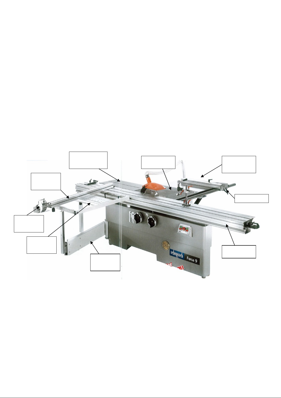
Main Table
Fence
Sliding Table
HF0000
W872
Hafco
Setup Procedure
FORSA-9
SCHEPPACH PANEL SAW
to be used in conjunction with
factory manuals supplied
Table Length
Cross Cut
Rail
Extension
Table Width
Extension
Adjustable
Support
Outrigger
Table
Table Stroke
Max wide rip capacity 1320
Saw blade
Blade bore
Max depth of cut @ 90° 107mm
Max depth of cut @ 45° 75mm
Cutting speed
Tilt
Scribe blade
Bore
Max height
3200mm
315mm
30mm
66m/sec
90° - 45°
120
20
4mm
Telescopic
Arm
Page 1 of
6
Page 2

There are five boxes containing the parts for the saw, the serial number should be on each box and they
should all have the
into boxes
1.
Place the main
using the four jacking bolts
HF0000
same number, because the machine is set in the factory and then dismantled and packed
table
in position and level
2. M
ount the sliding table to the main table by
lowering it over th
nuts should be factory set to the correct height
Adjust the height of the sliding table so that it is
0.3mm above the main table, this is to stop the
material dragging on the main table as it passes
through the blade
3. D
o not
tighten the main bolts at this stage, nip
them up until the sliding table is squared up
e six mounting studs, the nyloc
,
Page 2 of
6
Page 3

4.
Before tightening the main bolts pull the table
towards the main table tight against the two
adjusting blots
5.
Mount a dial indicator as shown
traverse it along the blade then
the
sliding table
adjusting screws
6.
The sliding table should be square to
the blade to a tolerance of +/- 0.1mm
and
adjust
if necessary by using
.
HF0000
7.
Tightened main bolts
8.
Fix the mounting brackets to the table
w
idth
extension, then fit the extension
to the main table, adjust so that the
side extension table is flush with the
main table
Page 3 of
6
Page 4

9.
Outer end of the
can be levelled using the two adjusting bolts
table width
extension table
HF0000
10. Fit
11. Fit the fence to the rail and slide up to the
12. Adjust the rail until the fence is square to
13. With the fence against the blade adjust
the fence rail to the table and nip the
bolts up
blade and lock in position
the blade and tighten bolts
the indicator
plastic indicator holding screws and
repositioning the indicator
to zero by loosening the
14. Fit the
15. This can be adjusted by the mounting
16. The outer end is adjusted by the
table length
so that it sits just below the surface of the
main table
bolts for th
stabilising leg
e hinge pins
extension and adjust
Page 4 of
6
Page 5

17. Place fence across the sliding table and measure from
the fence to the top of the
measurement at the further most forward point of the
telescopic
point of travel
arm travel and t
telescopic
hen again at the rear most
arm, do this
HF0000
18. Adjust the pivot pin until both readings are the same
19. Fit the
surfaces are flush
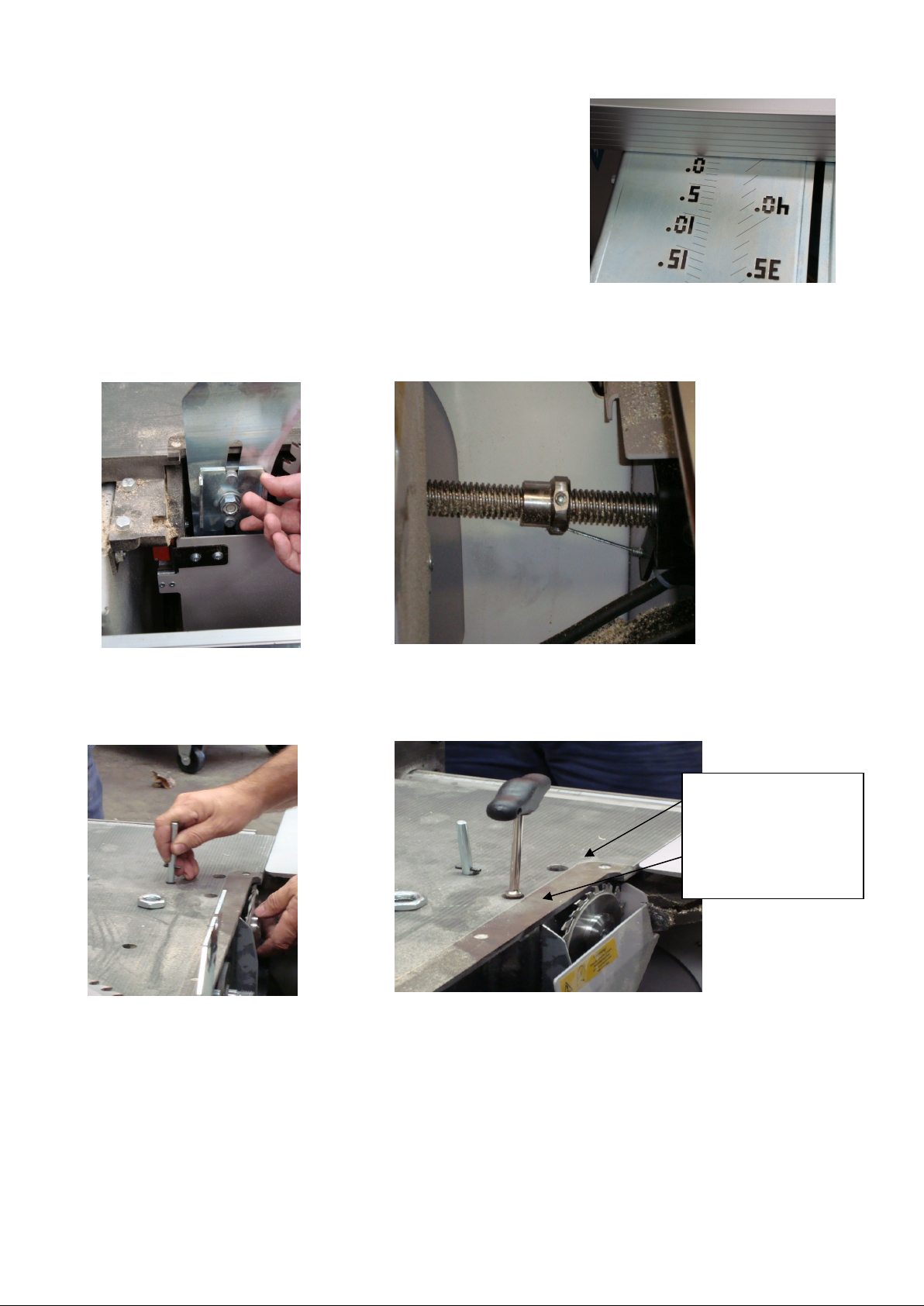
20. Fit
21. the
22. Adjust the whole
23. Place a set square against the blade and square the
to the blade with t
outrigger
crosscut rail
crosscut rail
a.
from the blade
table to the sliding table so that both
to the sliding table and fit t
and lock it in position at the 100mm mark
crosscut rail
he adjusting screw
until the face of the stop is 100mm
he adjustable stop to
crosscut rail
Page 5 of
6
Page 6
blades
Rear bolt adjusts blade
HF0000
24. The
MAIN SPINDLE
The blade cover has a micro switch so the cover must be shut for
crosscut rail
loosening the whole plate and sliding until the zero mark lines
up with the fence
scale can also be adjusted to zero by
the saw to operate
The riving knife can be
adjusted to suit different
blades
Fit pin into spindle to
loosen blade nut
MAINTENANCE
At the end of each day wipe off sawdust and wipe down sliding surfaces with a rag wet with WD40
, both
The maximum blade ang
be set by this nut
To adjust scribe blade
position
le can
Front bolt adjusts
blade up or down
from side to side
Page 6 of
6
 Loading...