

Page 1
WA 1208 Operating and
Installation Instructions
1 Operating Instructions
1.1 Introduction
This instruction manual contains important information for the safe operation
of equipment supplied by Schaudt. Make sure you read and follow the safety
instructions provided.
The instruction manual should always be kept in the vehicle. All safety information must be passed on to other users.
1.2 Operation
The WA 1208 booster increases the charging voltage available in the caravan to up to 14.4V, meaning the caravan battery undergoes perfect charging
when moving. It does not have any controls.
Y
For the functionality described below, it is a requirement that the 13-pin
connector plug on the towing vehicle is assigned in accordance with EN
1648-1. Also refer to the circuit diagram in Section 2.2.
Function
Itworksasfollows:
³ Hook up the caravan to the towing vehicle and plug the caravan connec-
tor into the vehicle.
³ Switch on the ignition and start the engine.
F
The 12 V supply voltage from the towing vehicle supplies the booster.
The green LED on the booster is ON.
F
This increases the voltage to 14.4 V. A battery connected to the booster in the caravan is charged with up to 9 A.
³ Switch off the ignition.
F
The 12 V supply voltage from the towing vehicle is isolated from the
caravan by the booster.
F
The green LED on the booster is OFF.
Y
The 13-pin connector plug on the caravan is automatically dead if it is
pulled out of the socket on the towing vehicle. This prevents the caravan
battery from discharging as a result of leakage currents.
Y
A TTENTION!
As long as the ignition on the towing vehicle is switched on, the booster is
active and the caravan battery is therefore charged. This discharges the towing vehicle battery.
This is why, when the vehicle is stationary and the caravan is plugged in, the
ignition may not stay on for a long period of time without the engine running.
E Schaudt GmbH, Elektrotechnik und Apparatebau, Planckstraße 8, 88677 Markdorf, Germany, Tel. +49 7544 9577-0, Fax +49 7544 9577-29, www.schaudt--gmbh.de
820.508 BAMA / EN
Date: 22.06.2010
Page 2
Operating and Installatio n Instructions for Battery Booster WA 1208
1.3 Faults
Flat
vehicle fuses
The majority of power supply system faults are caused by blown fuses.
Please contact our customer service department if you cannot rectify the
fault using the following table.
Fault
LED on the booster is not ON
when the ignition is switched
on although the caravan is
hooked up and the connector
on the towing vehicle is plugged in.
LED on the booster is ON but
the caravan battery does not
charge.
Possible cause Remedy
No 12V supply. Check the socket assignment
Cabling between caravan and
booster connector plugs defective.
One of the fuses is defective. Check the fuses and swap out
Booster defective Replace the booster
Cabling between booster and
battery defective.
One of the fuses is defective. Check the fuses and swap out
Booster defective Replace the booster
on the towing vehicle:
! Contact a car
workshop
Check the connector assignment on the caravan:
! Contact a
dealer
Check cable and plug connector, and replace/repair as necessary
the defective one.
Check cable and plug connector, and replace/repair as necessary
the defective one.
1.4 Maintenance
The booster does not require maintenance.
2 Installation instructions
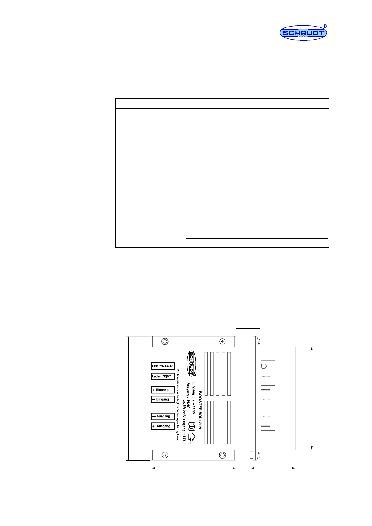
2.1 Mechanical installation
130
2.5
108
89
Fig. 1 Dimension diagram of the WA 1208 booster
2
Date: 22.06.2010 820.508 BAMA / EN
47.5
Page 3

Operating and Installatio n Instructions for Battery Booster WA 1208
Environment
Minimum clearance
Fitting
2.2 Electrical connection
³ Install in a dry, sufficiently ventilated location.
³ Ensure a minimum clearance to the surrounding fixtures and fittings:
F
Maintain a gap of at least 5cm on all sides (except mounted side).
F
Ensure cables are routed properly.
F
The ambient temperature may not exceed +40 °C during operation.
Y
A TTENTION!
There is a risk of overheating when the required gaps are not adhered to or
when ventilation slits are covered.
Firmly screw the booster into place:
³ Secure the booster with two screws (diameter 3 mm) on an even surface
(any installation position).
Y
A TTENTION!
To prevent damage in the event of a fault, fuses must be inserted as in Fig.
2 depending on the cable cable cross-section (EN 1648-1 and 2).
Towing vehicle Caravan
15A
15A
+
+
--
--
Relay circuit ”+ Refrigerator” (connector no. 10)
From terminal 15 (voltage for igniti on ”ON”)
Connection material
9
10
13
11
Assignment of the 13-pin
socket to EN
9 + Charging line
10 + Refrigerator (charging ”ON”)
13 -- Charging line
1 1 -- Refrigerator
Fig. 2 Block diagram of LT 226 connection
Required for the connection:
F
2 fuse holders
+
Refrigerator
--
+
Input
-Output
2A
Charging ”ON”
WA 1208
15A
+
-Battery
1648-1:
820.508 BAMA / EN
F
1 x 2A fuse, 1 x 15A fuse
F
Insulated flat push-on contacts, 6.3 mm red (0.3...1.5 mm2) and blue
(1.0...2.5 mm
F
Add-on relay in the towing vehicle if necessary (accessory, Schaudt
2
)
part no. 922.050)
F
Cable (recommended: 0.75 mm2and 2.5 mm2)
Date: 22.06.2010
3
Page 4

Operating and Installatio n Instructions for Battery Booster WA 1208
Connection
2.3 Technical details
2.3.1 Mechanical details
Dimensions
Weight
1. Disconnect the caravan battery (remove the terminals).
2 Establish the electrical connections as in Fig. 2. Note:
F
Select cable cross-sections and fuses in accordance with EN 1648-1.
Recommendations:
+ and -- caravan connector on the booster input: 2.5 mm
+ and -- booster output on the caravan battery: 2.5 mm
Charging ”ON”: 0.75 mm
F
Mount the fuses near the voltage source:
2
+ Caravan battery: 15 A on the positive terminal of the caravan
battery
+ Charging line of car: 15 A (must be installed in the car)
Charging ”ON” (+ Refrigerator): directly at the point of common
coupling
ca.130x89x48(WxDxHinmm)
approx. 270 g
2
2
Casing
2.3.2 Electrical details
Input voltage
Suitable batteries
End-of-charge voltage
Charge current whilst
moving
Back current from
caravan battery when
ignition is ”OFF”
Input bias current when
the ignition is ”OFF”
2.3.3 Environmental parameters
Operating temperature
Storage temperature
Plastic, blue with screenprint
for 12V DC systems (9 t o 14.5 V)
6-cell lead acid or lead gel batteries, 35 Ah and above
14.4 V
Charging of the caravan battery by the towing vehicle alternator with typically 8 A for an input voltage of 12 V (between 7 and 9 A depending on the
input voltage and charge state of the caravan battery)
Less than 0.5 mA, after the device has cooled down
0 mA, for wiring as in EN 1648-1 (see also Fig.
-10 °Cto+40 °C
-20 °Cto+70°C
Humidity
4
Operation in dry environment only
CE
CE marked
Date: 22.06.2010 820.508 BAMA / EN
 Loading...