

Page 1
Operating and Installation Instructions
for the LT 320 Control Panel
(Solar Display)
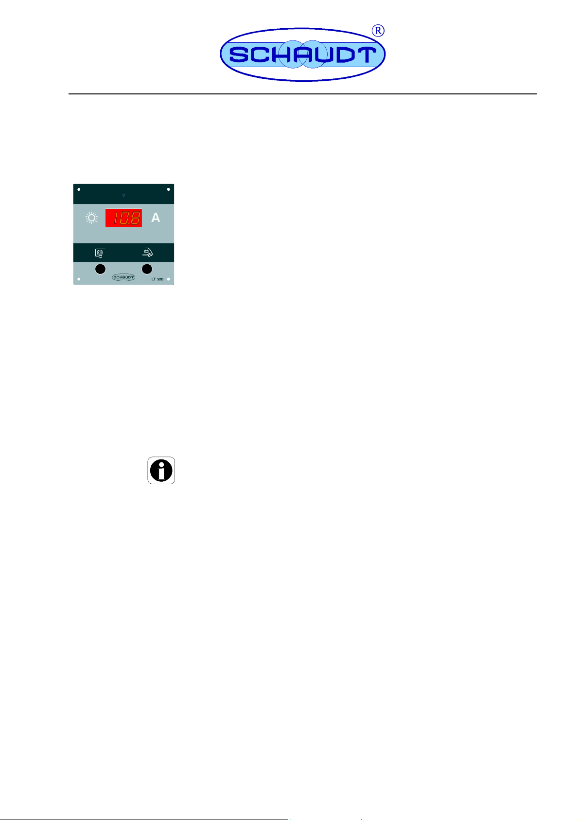
1 Operating instructions
1.1 Purpose
The L T 320 control panel enables the current charging current being supplied from
the solar regulator to the leisure area and starter batteries to be displayed.
The panel has 2 buttons and a three-digit 7-segment display for this purpose.
1.2 Operation
Press the ”Leisure Battery” button.
F The ”Leisure Battery” symbol and the current flowing into the leisure
battery are displayed.
F The display automatically goes out after about 20 seconds.
Press the ”Starter Battery” button.
F The ”Starter Battery” symbol and the current flowing into the starter
battery are displayed.
F The display automatically goes out after about 20 seconds.
Y Re-pressing the relevant button enables the current display to be swit-
ched off immediately.
Proceed as follows to have a continual display:
Press the ”Starter Battery” or ”Leisure Battery” button and keep it pres-
sed for longer than 5 seconds.
F The relevant symbol and the current flowing are displayed. The dis-
play does not go out until after 4 hours.
The continual display can be exited at any time by briefly re-pressing the
relevant button.
2 Installation instructions
2.1 Mechanical installatio n
The device is designed for installation into the front of a piece of furniture.
Install in a dry , sufficiently ventilated location.
Minimum clearance
Ensure a minimum clearance to the surrounding fixtures and fittings:
F The installation depth, including free space necessary for the connec-
tors and cables, is 35 mm.
F The ambient temperature may not exceed +50 C during operation.
E Schaudt GmbH, Elektrotechnik und Apparatebau, Planckstraße 8, 88677 Markdorf, Germany, Tel. +49 7544 9577-0, Fax +49 7544 9577-29, www.schaudt--gmbh.de
931.021 BAMA / EN
Date: 08.01.2015
Page 2
Operating and Installation Instructions LT 320
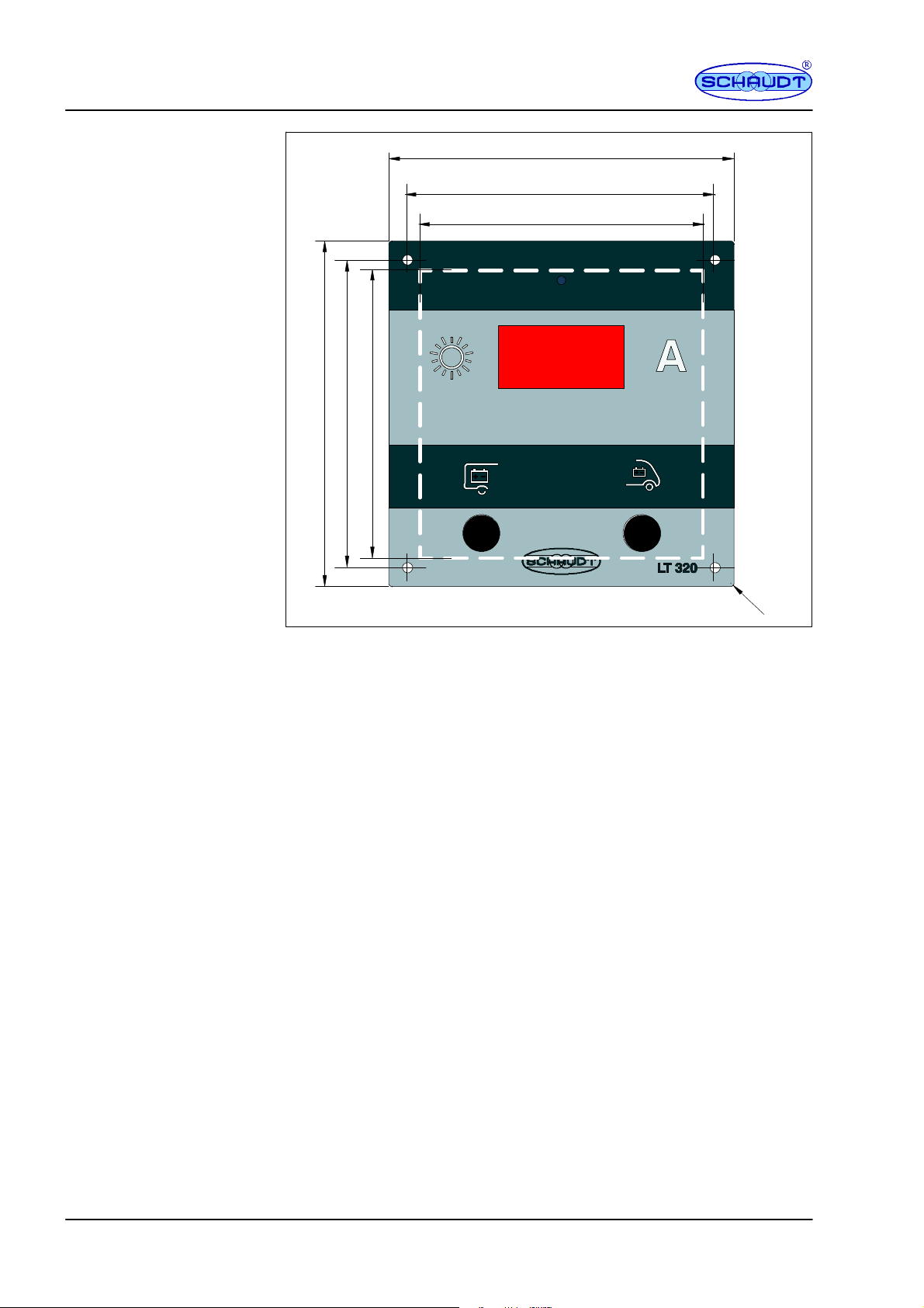
110
100
94*
Fitting
110R1100
Fig. 1 Dimensional diagram for LT 320 (dimensions in mm)
94*
* Dimensions for furniture cut-out, installation depth including plug-in connector
approx. 35 mm
Tighten the LT 320 control panel:
Establish an installation opening as in Fig. 1.
Mark out the hole pattern (see Fig. 1).
Pre-drill the holes (to 2 mm).
Use four x 2.9 cylinder head screws.
Ensure that the screws only gently touch against the front panel (until it is
no longer possible to move the panel).
2.2 Electrical connection
The L T 320 control panel is intended for connecting to Schaudt solar regulators
F LRM 1218 (MPP regulator)
F LR 1218 (series regulator)
Appropriate 4-pin connector cables (LRM 1218) and a connector set
(LR 1218) are available for these.
2
Date: 08.01.2015 931.021 BAMA / EN
Page 3

Operating and Installation Instructions LT 320
4 +12V supply
3 Ground (GND)
2 Solar current signal, starter battery
1 Solar current signal, leisure battery
Fig. 2 LT 320 signals
Connecting the LRM 1218 with the 4-pin connector cable
Plug the 4-pin Lumberg connector on the relevant connector cable into
the L T 320 control panel (see Fig. 2).
Plug the 4-pin Lumberg connector on the relevant connector cable into
the solar regulator (the ”Solar charging currents signal” connector).
Y If the connector cable is too long, it can be coiled up and secured at a
suitable place within the vehicle.
LR 1218 connector with connector set
F
1A
Leisure
battery
Yellow
+--
Green
Brown
White
LT 320
LR 1218
Fig. 3 Circuit diagram for connecting the LT 320 to the LR 1218
(the solar module and starter battery connectors are not shown)
The following parts are included in the connector set to connect the LT 320
control panel:
F One connector cable with a 4-pin Lumberg connector on one side and
four x 6.3 mm plug connectors on the other
F 2 x Y-type plug connectors
931.021 BAMA / EN
F Afuseholderwitha1Afuse
F Three x 5 cm long cables (each with 2 x 6.3 mm plug connectors).
Plug the 4-pin Lumberg connector on the relevant connector cable into
the L T 320 control panel (see Fig. 3).
Establish the connection on the LR 1218 solar regulator as in Fig. 3.
Date: 08.01.2015
3
Page 4

Operating and Installation Instructions LT 320
Y ATTENTION!
Be sure to observe the correct polarity when plugging the cables into the
leisure battery. An incorrect connection will result in irreparable damage to
the solar regulator and panel.
Y If the connector cable is too long, it can be coiled up and secured at a
suitable place within the vehicle (such as near the solar regulator). It is
also possible to shorten the cable and fix to it four new 6.3 mm flat pushon contacts (not included in the delivery).
2.3 Maintenance
The L T 320 control panel requires no maintenance.
2.4 Technical details
2.4.1 Mechanical details
Dimensions
Weight
Casing
2.4.2 Electrical details
Operating voltage
Standby current
Display
2.4.3 Environmental parameters
Operating temperature
Storage temperature
Humidity
CE
2.5 Storage -- packaging -- transportation
Customer service
address
110 x 110 x 35 (W x H x D in mm), D = depth, including connectors
75 g
Acrylic glass; printed on both sides, anthracite grey / white aluminium
For 12 V DC systems (10.5 to 15 V)
Approx. 3 mA
3-digit 7-segment display; 0,2 ... 25 A, resolution 0.1 A
-10 Cto+50C
-20 Cto+70C
Operation in dry environment only
CE marked
Only transport and store the unit if the packing is suitable and ambient
conditions are dry.
Schaudt GmbH, Elektrotechnik & Apparatebau
Planckstraße 8
88677 Markdorf, Germany
Phone: +49 (0)7544 9577-16
Email: kundendienst@schaudt-gmbh.de
Web: www.schaudt-gmbh.de
Send in device
4
Returning a faulty device:
Always use well-padded packaging.
Include the fault report.
Send it to the addressee (free delivery).
E
No part of this manual may be reproduced, translated or copied without express written permission.
Date: 08.01.2015 931.021 BAMA / EN
 Loading...