

Page 1
Operating Instructions
Electroblock EBL 211
Table of contents
1 Safety information 2......................................
1.1 Meaning of safety symbols 2...............................
1.2 General safety information 2...............................
1.3 Liability limitation 3.......................................
2 Introduction 3............................................
3 Operation 4..............................................
3.1 Switching system on and off 4..............................
3.2 Changing the battery 5....................................
3.3 Operating faults 6........................................
3.4 Shutting down 7..........................................
4 Application and functions in detail 9.........................
4.1 General 9...............................................
4.2 Battery functions 10........................................
4.3 Additional functions 10.....................................
5 Technical details 1 1........................................
5.1 Mechanical details 1 1......................................
5.2 Electrical details 1 1........................................
6 Maintenance 12...........................................
Appendix 13..............................................
E Schaudt GmbH, Elektrotechnik und Apparatebau, Planckstraße 8, 88677 Markdorf, Germany, Tel. +49 7544 9577-0, Fax +49 7544 9577-29, www.schaudt--gmbh.de
9110476 BA / EN Date: 22.01.2016
Page 2
Operating Instructions Electroblock EBL 211
1 Safety information
1.1 Meaning of safety symbols
Y DANGER!
Failure to comply with this sign may result in danger to life or physical condition.
Y WARNING!
Failure to comply with this sign may result in injury.
Y ATTENTION!
Failure to comply with the sign may result in damage to equipment or other
connected loads.
1.2 General safety instructions
The design of the device is state-of-the-art and complies with approved safety regulations. Failure to observe the safety instructions may nonetheless
lead to injury or damage to the device.
Only use the device when it is in perfect technical condition.
Any faults affecting the safety of individuals or the proper functioning of the
device must be repaired immediately by specialists.
Y DANGER!
Parts carry 230V mains voltage.
Risk of fatal injury due to electric shock or fire:
F Do not carry out maintenance or repair work on the device
F If cables or the device housing are damaged, no longer use the device
and isolate it from the power supply
F Ensure that no liquids enter the device
F The mains connection line may only be replaced by an authorised cu-
stomer service department or by those qualified.
Y WARNING!
Hot components
Burns:
F Only change blown fuses when the device is fully de-energised
F Blown fuses may only be replaced once the cause of the fault is
known and has been rectified
F Never bypass or repair fuses
F Only use original fuses rated as specified on the device
F Device parts can become hot during operation. Do not touch them.
F Never store heat sensitive objects close to the device (e.g. tempera-
ture sensitive clothes if the device has been installed in a wardrobe)
2
Date: 22.01.2016 9110476 BA / EN
Page 3
Operating Instructions Electroblock EBL 211
1.3 Liability limitation
All technical information, data and instructions pertaining to installation, operation and maintenance contained within this operating manual and associated installation guide were up-to-date when the documents were printed, and
were compiled in good faith in due consideration of experience and findings
gained previously.
No legal claims can be derived from the specifications, illustrations and descriptions in this operating manual or associated installation guide.
The manufacturer assumes no lability for damage due to:
F a failure to comply with this operating manual and associated installa-
tion guide
F improper assembly and/or installation
F non-intended use
F improper repairs
F technical modifications
F use of unapproved spare parts
2 Introduction
This instruction manual contains important information for the safe operation
of equipment supplied by Schaudt. Make sure you read and follow the safety
instructions provided.
The operating instructions should always be kept in the vehicle. All safety information must be passed on to other users.
Y This device is not intended to be used by those (including children) with
limited physical, sensory or mental aptitude or lack of experience and/or
knowledge unless they are supervised by a person responsible for their
safety or have received instruction from this person as to how the device
is used.
Children must be supervised to ensure they do not play with the device.
This device is intended for installation into a vehicle.
9110476 BA / EN
Date: 22.01.2016
3
Page 4
Operating Instructions Electroblock EBL 211
3 Operation
The electroblock is operated solely from the operator and control panel connected (apart from battery isolation).
Operation of the electroblock is not required for daily use.
Settings only have to be configured when the battery type is changed (AGM
or lead-gel), during initial start-up or when retrofitting accessories (refer to
Section 3.2 and the installation instructions EBL 21 1).
3.1 Switching system on/off
Y ATTENTION!
Incorrect electroblock settings.
Damage to connected devices. Therefore prior to starting:
F Ensure the leisure area battery is connected.
F Ensure that the battery selector switch (Fig. 4, Pos. 5) is set to the
correct position for the battery inserted.
F Ensure that the AES fuse (Fig. 4, Pos. 3) is only inserted when an
AES refrigerator is connected. The leisure area battery may totally
discharge otherwise. Damage to the battery is possible.
Battery cut-out
12 V main switch
(on operator and control
panel)
Operation with solar
regulator
Use on a 230 V
generator or car ferries
Deactivate the battery cut-out (shutdown) as required (refer to Section 3.4)
Use the main 12 V switch (see instruction manual of relevant control and
switch panel) to switch on/off all the consumers and the control and switch
panel.
Exceptions:
F Step
F Frost protection valve
F AES refrigerator
Please refer to the operating instructions for the operator and control panel
for further information.
Y ATTENTION!
If there is no backup function for the battery, damage to devices connected
may result. So therefore:
F Do not operate solar regulator without battery connected.
If a current generator is used for the 230V motorhome supply, the generator must not exceed the mains connection ratings (see ”Technical details”,
Section 5.2).
Y ATTENTION!
F To avoid voltage peaks during warm-up, do not connect the generator
until it is running in a stable manner. Otherwise the electroblock, the
12 V consumers or other devices connected could suffer damage. It is
essential the generator conforms to mains supply specifications.
4
Date: 22.01.2016 9110476 BA / EN
Page 5
Operating Instructions Electroblock EBL 211
3.2 Changing the battery
Y ATTENTION!
Use of incorrect battery types or incorrectly rated batteries.
Damage to the battery or devices connected to the electroblock:
F Batteries may only be changed by qualified personnel.
F Follow the battery manufacturer’s instructions.
F Only use the electroblock to connect to 12V power supplies with re-
chargeable 6-cell lead-gel or AGM batteries. Do not use any unsuitable battery types.
Y Normally only batteries of the same type and capacity should be used,
i.e. the same as those installed by the manufacturer.
Changing the battery
" Electrically isolate the battery from the electroblock. For this, activate the
battery cut-out (refer also to Section 3.4).
" Remove ”+ solar cell” connector on the solar charge regulator (if availa-
ble).
" Isolate the electroblock from the mains voltage (230V AC).
" Replace the battery.
" After changing the battery, recheck which type of battery has been inser-
ted.
Y DANGER!
Incorrect setting of the battery selector switch.
Risk of explosion due to build up of explosive gases:
F Move the battery selector switch to the correct position
Y ATTENTION!
Incorrect setting of the battery selector switch.
Damage to the battery.
F Move the battery selector switch to the correct position
" Disconnect the electroblock from the mains before adjusting the battery
selector switch.
Y
However, suitability must be checked on a case-by-case basis using the
specifications from the battery manufacturer and the charging parameters of the electroblock.
The charging parameters are specified in Section 5.2.
9110476 BA / EN
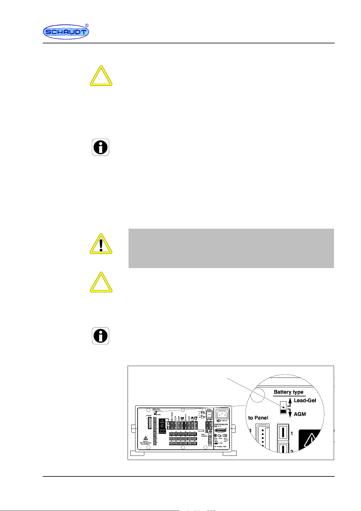
Fig. 1 Battery selector switch
Date: 22.01.2016
1
5
Page 6

Operating Instructions Electroblock EBL 211
g
g
t
lybelow1
3.3V)Havethemainsvoltag
e
Starterbatteryisnotchar
NomainsvoltageSwitchontheautomati
c
g
g
below13.0V)
g
p
" Move the battery selector switch (Fig. 1, Pos. 1) to the correct position
using a thin object (such as a ballpoint pen):
F Lead-gel battery: Move the battery selector switch to ”Lead-gel”.
F AGM battery: Move the battery selector switch to ”AGM”.
Starting up
the system
3.3 Faults
Flat
vehicle fuses
" Plug the ”+ solar cell” connector into the solar charge regulator (if availa-
ble).
" Start up the system as described in section 3.1.
A fault in the power supply system is usually caused by a blown fuse.
For faults with the control and switch panel, the entire system must be switched off from the battery cut-off and turned on again after about 1 minute.
Please contact our customer service address if you cannot rectify the fault
using the following table.
If this is not possible, such as when you are abroad, a specialist workshop
will be able to repair the device. In this case, you must ensure that the warranty is not invalidated by incorrect repairs being carried out. Schaudt GmbH
will not accept any liability for damage resulting from such repairs.
Fault Possible cause Remedy
Leisure area battery is not
charged during 230 V
operation (battery voltage
constan
Leisure area battery is
overcharged during 230 V
operation (battery voltage
constantly above 14.5 V)
Starter battery is not char- No mains voltage Switch on the automatic
ged during 230 V operation (battery voltage constantly below 13.0 V)
Leisure area battery is not
charged during mobile
operation (battery voltage
The leisure area battery is
overcharged during mobile operation (battery voltage permanently above
14.3 V)
The refrigerator does not
work during mobile operation
No mains voltage Switch on the automatic
fuse in the vehicle
Have the mains voltage
checked
Defective electroblock Contact customer service
Defective electroblock Contact customer service
fuse in the vehicle
Have the mains voltage
checked
Defective electroblock Contact customer service
Defective alternator Have the alternator chek-
ked
No voltage on D+ input Check fuses and wiring
Defective electroblock Contact customer service
Defective alternator Have the alternator chek-
ked
No power supply to the refrigerator
Defective electroblock Contact customer service
Defective refrigerator Havetherefrigeratorchek-
Have the fuse and cabling
checked
ked
6
Date: 22.01.2016 9110476 BA / EN
Page 7

Operating Instructions Electroblock EBL 211
g
)
Solarchargeregulatornot
Pluginsolarchargeregu
DefectivefuseorcablingHavethefuseandcabling
p
ply
No12Vsupplyinthelei
12Vmainswitchforlei
Switchonthe12Vmai
n
y
BatterycutoutactivatedDeactivatethebatterycut
DefectivefuseorcablingHavethefuseandcabling
b
lock
iblef
Fault RemedyPossible cause
Solar charger does not
work (power supply and
engine are off)
No 12 V su
sure area
Operation of the electro-
not poss
the control panel.
in the lei- 12Vmain switchfor lei- Switch on the 12Vmain
rom
Solar panel in (partial)
shade or covered (snow or
dirt)
Solar charge regulator not Plug in solar charge reguplugged in
Defective fuse or cabling Have the fuse and cabling
Solar charge regulator defective
sure area battery switched
off battery.
Battery cut-out activated Deactivate the battery cut-
Defective fuse or cabling Have the fuse and cabling
Defective electroblock Contact customer service
Defective electroblock Contact customer service
Move solar panel out of
shade or clean it.
lator
checked
Have solar charge regulator checked
switch for the leisure area
out
checked
Y The charging current is reduced automatically if the device becomes too
hot due to excessive ambient temperature or lack of ventilation. Always
prevent the device from overheating nevertheless.
Y If the automatic shutdown mechanism of the battery monitor is triggered,
fully charge the leisure area battery.
3.4 Closing down
3.4.1 Closing down the system
Y ATTENTION!
Total discharge results in damage to the leisure area battery. So therefore:
F Fully charge the leisure area battery before and after a shutdown
(connect the vehicle to the mains for at least 12 hours and 24 hours
for an 80Ah and 160Ah battery respectively)
Y ATTENTION!
Exceeding permitted input voltages can cause damage to consumers connected. So therefore:
F Do not operate the solar charge regulator without a battery.
F When the battery is changed or removed, first unplug the ”+ solar cell”
connector on the solar charge regulator.
Isolate the leisure area
battery from the
on-board 12 V supply
Disconnect the leisure area battery from the 12V power supply when the
motorhome is not used for a longer period (during the winter for example).
For this, the system has a battery cut-out mechanism which isolates electrically the leisure area battery from the vehicle.
9110476 BA / EN
Date: 22.01.2016
7
Page 8

Operating Instructions Electroblock EBL 211
" Fully charge the leisure area battery before closing down the system.
" Switch off the 12V main switch on the control panel.
" Move battery cut-out switch (switch, see Fig. 4, Pos. 5) to position ”Bat-
tery OFF”.
The battery cut-out switch isolates the following connections from the leisure
area battery:
F 12V consumers
F Frost protection valve
F Operator and control panel
" Remove the step fuse (refer to Fig. 4, Pos. 6) on the electroblock
" For vehicles with AES refrigerator:
Remove the AES fuse (refer to Fig. 4, Pos. 3) on the electroblock
Y The battery alarm is no longer active.
The frost protection valve opens for certain heater systems when the leisure area battery is isolated from the electroblock via the battery cut-out.
The boiler and water tank empty when the frost protection valve is open.
See the instruction manual for the heater system for further information.
The leisure area battery is also charged by the internal charger module,
an additional battery-charger, the solar charger regulator and the alternator when the battery cut-out is activated.
3.4.2 Cancelling the shutdown
" Move battery cut-out switch (switch, see Fig. 4, Pos. 5) to position ”Bat-
tery ON”.
" Insert the step fuse (refer to Fig. 4, Pos. 6) on the electroblock
" For vehicles with AES refrigerator:
Insert the 15A AES fuse (refer to Fig. 4, Pos. 3) on the electroblock
" After having disconnected the leisure area battery from the electroblock
using the battery cut-off switch or after changing the battery, briefly
switch on the 12 V main switch on the control and switch panel to start up
the consumers.
8
Date: 22.01.2016 9110476 BA / EN
Page 9

Operating Instructions Electroblock EBL 211
4 Application and functions in detail
4.1 General
Y This device is intended solely for installation in a vehicle.
The electroblock is the central energy supply device for all 12 V consumers
in the electrical system on board the motorhome/caravan. It is normally located inside a cupboard or storage area and is accessible from the front for
fuse changes.
Modules
Operator and
control panel
DT / LT / IT ...
Solar
regulator
LR / LRS ...
(accessory)
Electroblock
EBL 211
+--
Starter battery
+--
Leisure area battery
Fig. 2 On-board power supply system
12V consumers
The EBL 211 electroblock comprises:
F a charge module for charging all batteries connected
230V AC
Lighting
Pump
Heater
etc.
Protective circuits
9110476 BA / EN
System devices
F the complete 12V distribution unit
F the fuses for the 12V circuits
F a main switch module
F battery monitor
F other control and monitoring functions
A control and switch panel must be connected for operation. This device
controls the electrical functions in the motorhome’s leisure area as well as
the accessories.
There is a connection for a solar charge regulator.
Flat vehicle fuses protect the various circuits. Exceptions here are the step
and the frost protection valve.
F Excess temperature
F Overload
F Short circuit
Date: 22.01.2016
9
Page 10

Operating Instructions Electroblock EBL 211
4.2 Battery functions
Suitable batteries
Battery cut-out
Battery selector switch
Battery monitor with
automatic disconnect
6-cell AGM or lead-gel batteries, 55 Ah and above
The battery cut-out (at the battery cut-out switch of the electroblock, see Fig.
4, Pos. 15, see also Section 3.4) isolates the following connections from the
leisure area battery:
F all 12 V consumers
F the frost protection valve
This prevents slow discharge of the leisure area battery by the standby current during shutdown of the vehicle (discharge with approx. 4 Ah in month).
The batteries can still be charged using the electroblock, the alternator, an
auxiliary charging unit or the solar charge regulator, even when the battery
cut-out switch is switched off.
The switching option provided by the battery selector switch ensures optimum charging of the two battery types, lead-gel and AGM.
The battery monitor compares the voltage of the leisure area battery with a
reference voltage. As soon as the battery voltage falls below 10.5 V, all 12 V
consumers are switched off. Only the step, the frost protection valve and the
AES refrigerator are still powered. The automatic disconnector is not triggered by short-term low voltage (shorter than 2 seconds), caused by high current when switching on consumers.
If an overload or an insufficiently charged leisure area battery causes the
voltage to fall so low that the automatic disconnector is triggered, any nonessential consumers should be switched off.
4.3 Additional functions
Automatic switch
function for
AES/compressor
refrigerator
Step fuse
Battery charging with
solar charging regulator
Automatic switch
function for awning light
It may be the case that only the 12 V supply is started
for a short time. For this, switch on the 12V main switch on the control and
switch panel.
However, if the battery voltage remains below 11.0 V, you cannot switch the
12 V power supply back on.
Fully charge the leisure area battery as soon as possible. For more information, see the description of ”battery voltages”.
This relay supplies the AES/compressor refrigerator with power from the
starter battery when the vehicle engine is running and the D+ connection is
live. An AES/compressor refrigerator is powered by the leisure area battery
when the vehicle engine is not running.
The ”Step” output is fused with a 15 A fuse and is supplied continually, even
whenthemain12VswitchisOFF.
Maximum permitted charge current 14 A, protected with 15 A
Depending on the solar charge regulator used, either only the leisure area
battery is charged or the leisure area battery and the starter battery.
The awning light only works when the power supply is on, the vehicle engine
is off and the D+ connection is not live.
10
Date: 22.01.2016 9110476 BA / EN
Page 11

Operating Instructions Electroblock EBL 211
Mains charging
starter battery
5.1 Mechanical details
Dimensions
Weight
Casing
Front
5.2 Electrical details
Mains connection
Current consumption
Suitable batteries
Standby current from
leisure battery
This feature provides an automatic float charge for the starter battery at up
to 2 A when the 230 V mains is connected to the electroblock.
5 Techn ical details
130 x 275 x 170 (H x W x D in mm), including attachment feet
2.0 kg
PA (polyamide), gentian blue (RAL 5010)
Aluminium, powder coated, light grey (RAL 7035)
230 V AC voltage 10 %, 47--63Hz sinewave, protection class I
1.9 A
6-cell lead-gel or AGM batteries, 80 Ah and above
Dependent on the control panel: approx. 1 mA, plus consumption of refrigerator control electronics
D+ loading
Current-carrying
capacity
Battery charging via
mains connector
Conditions for the measurement:
F approx. 10 minutes after disconnection from the mains
F 12.6 V battery voltage
F Battery alarm OFF
F Battery cut-out switch ON
F Lighting for operator and control panel OFF
F All consumers switched off
F 12 V main switch OFF
Loading of D+ output of the alternator by the electroblock approx. 0.5 mA
without current consumption on D+ point
12 V outputs A maximum of 90% of the nominal current
of the relevant fuse may be
drawn.
Frost protection valve output max. 0.1 A
D+ point 1 A for fusing D+ input with 2 A
Leisure area battery
Battery selector
lead-gel AGM
switch setting
Charging curve IUoU IUoU
Final charge voltage 14,4V/16h 14,7 V / 4 h
Charge current 18 A 18 A
Voltage for
trickle charge
13,7 V with automatic
switchover
13,7 V with automatic
switchover
9110476 BA / EN
Date: 22.01.2016
11
Page 12

Operating Instructions Electroblock EBL 211
Battery charging of the
starter battery
IUoU curve
Starter battery
Charge current trickle charge max. 2 A
Charging voltage typ. U
Wbat
-- 0 , 2 V
New charge cycle, for battery voltage < 13.7 V
switchover to main charging with approx. 5 seconds delay
U
charge
V
Main charge
I
Lead-gel:14.4V
AGM: 14.7 V
Lead-gel:13.7V
AGM: 13.7V
Fig. 3 Charging voltage with EBL 211 electroblock
Full charge
Uo
16 h for lead-gel
4hforAGM
Trickle charge
U
Tim e
I Main charge with maximum 18 A charging current, electronically limi-
ted, up to final charging voltage. Start of charge also for completely
discharged batteries.
Uo Automatic switchover to full charge with constant 14.4 V (lead-gel) or
14.7 V (AGM). The duration of the full charge phase is based on the
battery type and is set on the device.
Cleaning
U Automatic changeover to compensation charge with constant 13.7 V. In
the compensation charge phase, the voltage at the output of the charging module is constant.
Start of a new charging cycle by switching over to main charge, if the battery
voltage falls below 13.7 V for more than 5 seconds when loaded. Start of
charge also for completely discharged batteries. The internal charge module
can also be operated without leisure battery.
6 Maintenance
The electroblock requires no maintenance.
Clean the electroblock with a soft, slightly damp cloth and mild detergent.
Never use spirit, thinners or similar substances. Do not allow liquids to enter
the electroblock.
12
E
No part of this manual may be reproduced, translated or copied without express written permission.
Date: 22.01.2016 9110476 BA / EN
Page 13

Operating Instructions Electroblock EBL 211
Appendix
A Special fittings/accessories
Controlpanel
Solar charge regulator
B Customer service
Customer service
Send in device
C Fault report
Schaudt DT ..., LT ... or IT ... control panel (required for operation)
Schaudt solar charge regulator, type LR ... , LRS ... or LRM ... for solar modules with a total charge current of 14 A with 3-pin connector (charging of
leisure area and starter batteries possible)
Schaudt GmbH, Elektrotechnik & Apparatebau
Planckstraße 8
88677 Markdorf
Germany
Phone: +49 7544 9577-16
Web: www.schaudt-gmbh.de
Email: kundendienst@schaudt-gmbh.de
Returning a faulty device:
" Complete and enclose the fault report, see Appendix C.
" Send it to the addressee (free delivery).
In the event of damage, please fill in the fault report and send it with the
faulty device to the manufacturer.
Device type: _______________________
Item no.: _______________________
Vehicle: Manufacturer: _______________________
Model: _______________________
Own installation? Yes - No Upgrade? Yes - No -
Following fault has occurred (please tick):
- Electrical consumers do not work -- which?
(please specify below)
- Switching on and off not possible
- Persistent fault
- Intermittent fault/loose contact
Other comments:
9110476 BA / EN
Date: 22.01.2016
13
Page 14

Operating Instructions Electroblock EBL 211
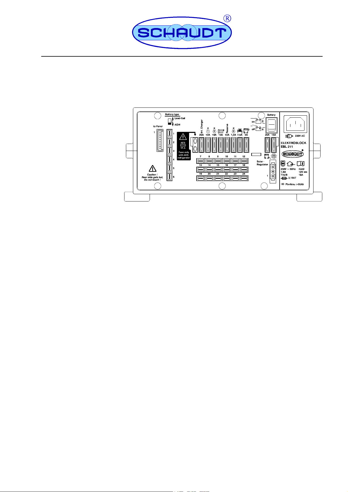
D Layout
1
13
Fig. 4 Layout of the EBL 211 electroblock (front)
23 4
12
1 Connector for control panel
2 Battery switchover (types gel / AGM)
3 Flat vehicle fuse for AES refrigerator
4 Flat vehicle fuses for consumers
5 Battery cut--out
6Stepfuse
7 Flat vehicle fuse for solar regulator
11
8
5
6
7
10
8 Mains connection
9 Housing
10 Connection block, solar regulator (supply)
1 1 6.3 mm consumer connectors
12 Connector block for batteries
13 Device feet
9
Fig. 5 Layout of EBL 211 electroblock (rear)
1 Cover
14
1
Date: 22.01.2016 9110476 BA / EN
Page 15

E Block diagram/wiring diagram
230V AC
230 V mains ~ 50 Hz
Low power device socket
LAS 1218
Charging relay B1
S 1218
Operating Instructions Electroblock EBL 211
* The negative terminals for leisure area
and starter batteries must be connected
to each other externally.
Changeover
switch
Lead-gel
AGM
Battery on / off
Battery cut--out switch:
Isolates the control panel and the frost protection valve of the
heater system from the battery to prevent standby currents during
shut--down.
Plug connector LF-- PA 401
6.3x0.8 -- 4x 6-way
+ Leisure area battery
+ Starter battery
D+ input
D+ point
+ sensor, leisure area battery
Negative leisure area battery sensor
Negative, leisure area battery*
Negative, leisure area battery*
Important
The fuse is only used
for an AES refrigerator
SB: Starter battery
WB: Leisure area battery
Batterycut--off relay
Batterymonitor
BW 208
Main
switch-rel
ay
Switching stage
Refrigerator
Awningl
ight
Circuit board KPL EBL 208
+ Starter battery
Shunt battery
Shunt consumer
+ sensor, leisure area battery
Mains indicator
12V On
12V Off
Negative leisure area battery sensor
12 V indicator
Pump switch
Lumberg MSFQ/0 10--way
+ Frost protection valve
Connected negative terminal of pump
Negative SB for refrigerator
Negative, refrigerator
+ refrigerator
+ SB for refrigerator
+WB
Solar-
-charge regulator
+SB
MNL 3--way socket housing
+Pump
+ Awning light
+ Heater
+ Light 1
+ Light 2
+ Spare
+ Light 3
+Step
9110476 BA / EN
Date: 22.01.2016
15
Page 16

Operating Instructions Electroblock EBL 211
(Blank page)
16
Date: 22.01.2016 9110476 BA / EN
 Loading...