

Page 1

Instruction Manual
Electrobloc EBL 99 K
EBL 99 K with OVP
Tab le of contents
1Safetyinformation 2......................................
1.1 Meaning of safety symbols 2...............................
1.2 General safety information 2...............................
2 Introduction 3............................................
3Operation 3..............................................
3.1 Starting up the System 3..................................
3.2 Changing the Battery 4....................................
3.3 System Faults 5..........................................
3.4 Closing down the System 6................................
4 Application and Functions in Detail 7........................
4.1 Battery Functions 8.......................................
4.2 Additional Functions 9.....................................
5 Maintenance 9...........................................
Appendix 10..............................................
E Schaudt GmbH, Elektrotechnik und Apparatebau, Planckstraße 8 88677 Markdorf, Germany, Tel. +49 7544 9577-0, Fax +49 7544 9577-29, www.schaudt--gmbh.de
811.419 BA / EN
Date: 20.01.2010
Page 2
Instruction Manual for Electrobloc EBL 99 K / EBL 99 K with OVP
1SafetyInformation
1.1 Meaning of safety symbols
Y DANGER!
Failure to heed this warning may result in death or serious injury.
Y WARNING!
Failure to heed this warning may result in personal injuries.
Y AT T E NTION!
Failure to heed this warning may result in damage to the device or connected consumers.
1.2 General safety information
The device is state-of-the-art and complies with approved safety regulations.
Nonetheless, personal injuries or damage to the device may occur if the safety instructions contained herein are not followed.
Ensure that the device is in perfect working order before use.
Any technical faults which may impact personal safety or the safety of the
device must be rectified immediately by qualified personnel.
Y DANGER!
230V mains voltage carrying parts.
Danger of death due to electric shock or fire:
F Do not carry out maintenance or repair work on the device.
F If cables or the device housing are damaged, no longer use the device
and isolate from the power supply.
F Ensure that no liquids enter the device.
Y WARNING!
Hot components!
Burns:
F Only change blown fuses when the device is completely de-energised.
F Only replace blown fuses once the cause of the fault has been identi-
fied and rectified.
F Never bypass or repair fuses.
F Only use original fuses rated as specified on the device.
F Device parts can become hot during operation. Do not touch.
F Never store heat sensitive objects close to the device (e.g. tempera-
ture sensitive clothes if the device has been installed in a wardrobe).
2
Date: 20.01.2010 811.419 BA / EN
Page 3
Instruction Manual for Electrobloc EBL 99 K / EBL 99 K with OVP
2Introduction
Y This device is intended solely for use in vehicles.
This instruction manual contains important information for safe operation of
the device. Ensure you read and follow the safety instructions provided.
The instruction manual should be kept in the vehicle at all times. Ensure that
other users are made aware of the safety regulations.
Y This device is not intended to be used by persons (including children)
with limited physical, sensory or mental aptitude or lack of experience
and/or knowledge unless they are supervised by a person responsible for
their safety or have received instruction from this person as to how the
device is used.
Children are to be supervised so as to ensure they do not play with the
device.
3Operation
The electrobloc is operated solely via the IT ... / LT ... control and switch panel connected. .
Overvoltage protection
OVP
3.1 Starting up the system
No operation of the EBL 99 K or EBL 99K with OVP electrobloc is required
for daily use (exception: the battery cut-off switch should be disabled when
the vehicle is not in use, see Section 3.4).
One-off settings only have to be configured when the battery type is changed (lead-acid or lead-gel), during initial start-up or when retrofitting accessories (see Section 3.2 and the assembly instructions).
The EBL 99 K with OVP electrobloc is suitable for all applications in which
the danger of overvoltage is especially large. For example, lightning strikes
to the national grid, generator operation, poor electronic installations or trips
to distance countries.
For this, an overvoltage protection unit is fitted in the electrobloc between
the mains connection and the charge module.
Y AT T E NTION!
Incorrect electrobloc settings.
Damage to connected devices. Therefore prior to starting:
F Ensure the leisure area battery is connected.
F Ensure that the battery selector switch (Fig. 3, Pos. 10) is set to the
correct position for the battery installed.
811.419 BA / EN
Turn the battery cut-off switch (see Fig. 3, Pos. 12) to ”On”.
Use the main 12V switch (see instruction manual of relevant control and
switch panel) to switch on/off all the consumers and the control and
switch panel.
Date: 20.01.2010
3
Page 4
Instruction Manual for Electrobloc EBL 99 K / EBL 99 K with OVP
Outputs are exceptions:
F Floor light/step
F Heater
F Frost protection valve
These outputs are not disabled via the main switch of the IT .. . /LT control
and display panel.
Please refer to the operating instructions of the IT ... /LT... control and
switch panel for further information. .
3.2 Changing the battery
Y AT T E NTION!
Use of incorrect battery types or incorrectly rated batteries.
Damage to the battery or devices connected to the electrobloc:
F Batteries should only be changed by qualified personnel.
F Follow the battery manufacturer’s instructions.
F Only connect the electrobloc to 12V power supplies with rechargeable
6-cell lead gel or lead acid batteries. Do not use any unsuitable battery types.
Y Normally only batteries of the same type and capacity should be used,
i.e. same as those installed by the manufacturer.
Y It is possible to swap lead acid batteries with lead gel batteries. However,
swapping from lead-gel-batteries to lead-acid-batteries is only possible in
certain cases. Contact the vehicle manufacturer for more information.
F AES/compressor refrigerator
F Spare 4
Changing the battery
Electrically isolate the battery from the electrobloc by disabling the bat-
tery cut-off switch on the electrobloc (also see Section 3.4).
Replace battery.
After changing the battery, recheck which type of battery has been inser-
ted.
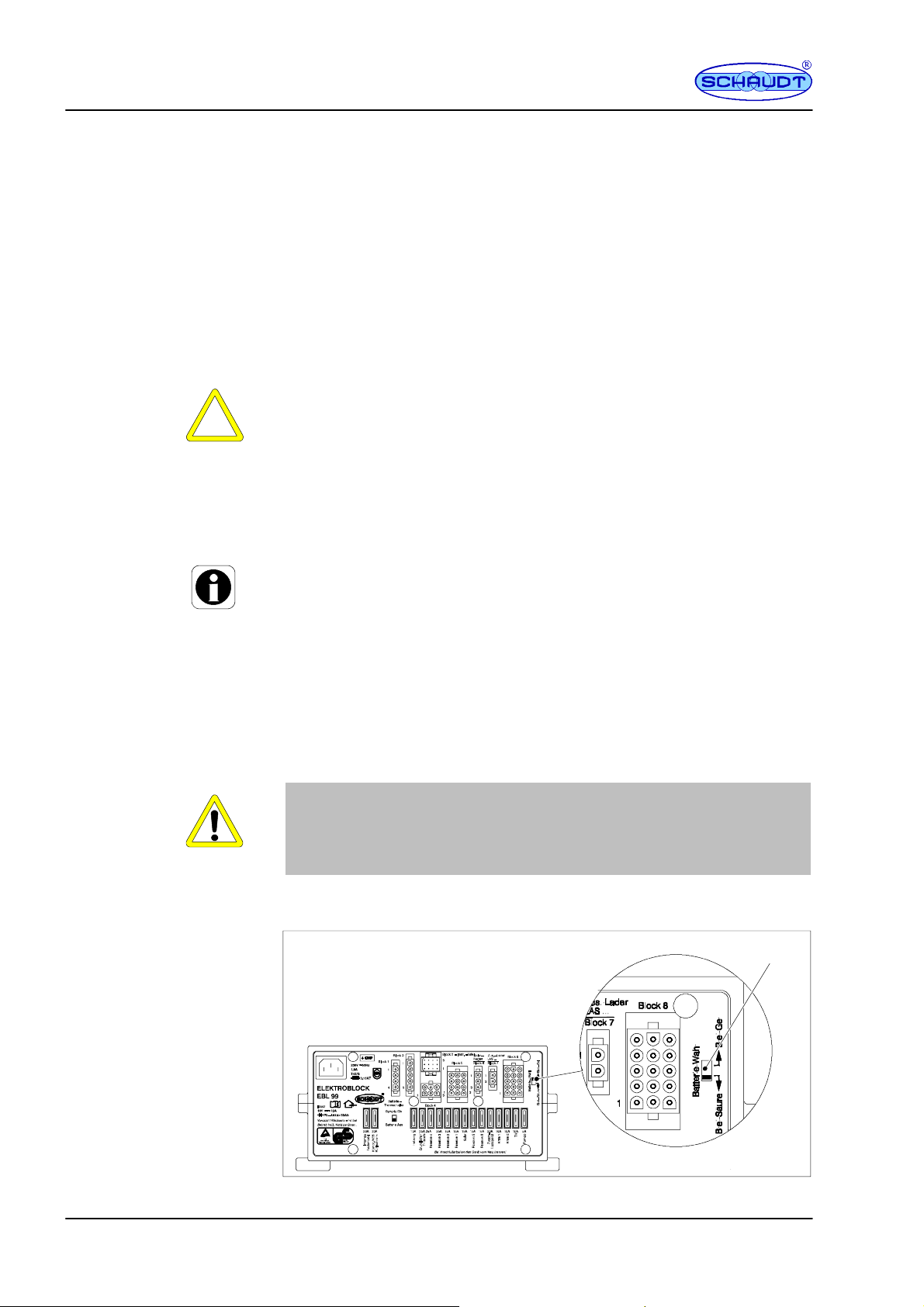
Y DANGER!
Incorrect setting of the battery selector switch.
Risk of explosion due to build up of explosive gases:
F Set the battery selector switch to the correct position.
Disconnect the electrobloc from the mains before adjusting the battery
selector switch.
1
Fig. 1 Battery selector switch
4
Date: 20.01.2010 811.419 BA / EN
Page 5
Instruction Manual for Electrobloc EBL 99 K / EBL 99 K with OVP
L
Livingareabatteryisno
t
NomainsvoltageSwitchontheautomati
c
g
g
;
Starterbatteryisnot
NomainsvoltageSwitchontheautomati
c
g
g
;
g
y
operation(batteryvoltag
e
p
Starting up
the system
3.3 System faults
Set the battery selector switch (Fig. 1, Pos. 1) to the correct position
using a thin object (e.g. a ballpoint pen):
F Lead gel battery: Set the battery selector switch to ”Lead-gel”.
F Lead acid battery: Set the battery selector switch to ”Lead-acid”.
Start up the system as described in Section 3.1.
Flat vehicle fuses
Discharged battery --
start motor
In most cases of a fault in the energy supply system, a flat battery or a faulty
fuse is the cause.
If the battery is discharged, consumers can always be supplied by starting
the motor of the base vehicle.
Please contact our customer service department if you can not rectify the
fault using the following table.
If this is not possible, e.g. if you are abroad, you can have the electrobloc
repaired at a specialist workshop. Please note that the warranty becomes
void if incorrect repair work is carried out. Schaudt GmbH can not accept
liability for any damages resulting from such repairs.
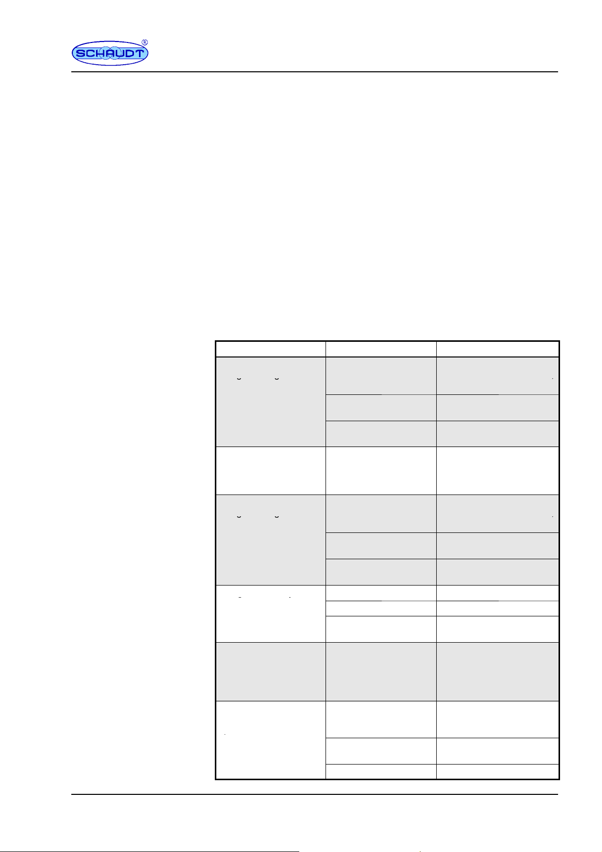
Fault Possible cause Remedy
ivingarea batteryis not No mains voltage Switch on the automatic
charged during 230V
operation (battery voltage
constantly below 13.3V)
Living area battery is
overcharged during 230V
operation (battery voltage
constantly above 14.5 V)
Starter batteryis not No mains voltage Switch on the automatic
charged during 230V
operation (battery voltage
constantly below 13.0V)
Living area battery is not
charged during mobile
below 13.0 V)
The living area battery is
overcharged during
mobile o p eration (battery
voltage constantly above
14.3 V)
The refrigerator does not
work during mobile
operation
Too m a ny c o n sumers a r e
switched on
Defective electrobloc Contact the customer
Defective electrobloc Contact the customer
Too m a ny c o n sumers a r e
switched on
Defective electrobloc Contact the customer
Defective alternator Check the alternator
No voltage on D+ input Check the fuse and wiring
Defective electrobloc Contact the customer
Defective alternator Check the alternator
No power supply to the
refrigerator
Defective electrobloc Contact the customer
Defective refrigerator Check the refrigerator
circuit breaker in the vehicle;
check the mains voltage
Switch off any consumers
not required
service department
service department
circuit breaker in the vehicle;
check the mains voltage
Switch off any consumers
not required
service department
service department
Check the fuse (20A of the
supply; possibly 2A of the
D+ signal) and wiring
service department
811.419 BA / EN
Date: 20.01.2010
5
Page 6
Instruction Manual for Electrobloc EBL 99 K / EBL 99 K with OVP
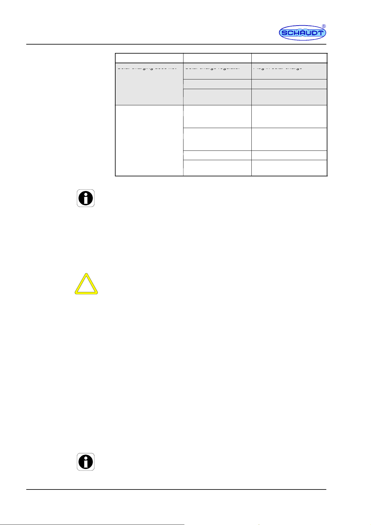
Solarchargingdoesno
t
Solarchargeregulato
r
Pluginsolarcharge
k
inthel
ivi
l
ivi
l
ivi
d
i
(
!
)
Def
C
heck
f
Fault RemedyPossible cause
Solar charging does not Solar charge regulator Plug in solar charge
work
12V supply does not
wor
Y If the device becomes too hot due to excessive ambient temperature or
ng area
lack of ventilation, the charging current is automatically reduced. Always
prevent the device from overheating nevertheless.
Y If the automatic shutdown mechanism of the battery monitor is triggered,
fully charge the living area battery.
not plugged in
Defective fuse or wiring Check fuse and wiring
Solar charge regulator
defective
12V main switch for the
ng areabatteryis
switched off
Not all plugs or fuses are
plugge
electrobloc
Defective electrobloc Contact the customer
nto the
ectivefuse or wiring
regulator
Check s olar charge
regulator
12V main switch for the
switched on
plug in all plugs and fuses
correct values
electrobloc
service department
ng areabattery mustbe
to the
use andwiring
3.4 Closing down the system
Closing down
The battery is isolated by switching off the battery cut-off switch.
Y AT T E NTION!
Total discharge.
Damage to the living area battery:
F Fully charge the living area battery before and after closing down the
system. (Connect vehicle tothemainswithan80Ahbatteryatleast
12 hours and with a 160Ah battery at least 24 hours).
Disconnect the living area battery from the 12V power supply if the motorhome is not used for a longer period (during the winter for example).
Fully charge the living area battery before closing down the system.
Switch off from the main switch of the IT ... /LT... control and switch pa-
nel.
Turn the battery cut-off switch (see Fig. 3, Pos. 12) to ”Off”. The following
connections are isolated from the living area battery:
F All 12V consumers
F Frost protection valve
F Control and switch panel
The living area battery is then protected against total discharge. This only
applies if the battery is intact. Follow the battery manufacturer’s instructions.
Y If the living area battery is isolated from the electrobloc with the battery
cut-off, the frost protection valve of the combination heating opens. A
loss of water is possible (see operating instructions of the combination
heating).
6
Date: 20.01.2010 811.419 BA / EN
Page 7

Instruction Manual for Electrobloc EBL 99 K / EBL 99 K with OVP
4Applicationandfunctionsindetail
The electrobloc is the central power supply unit for all 12V consumers in the
vehicle’s electrical system. It is usually located in a cupboard or storage area
and is accessible from the front in order to change fuses.
Control and
display panel
IT.../LT...
230V AC
Electrobloc
EBL 99 K
EBL 99 K with OVP
+--
Lighting
Pump
Heater
etc.
12V consumers
Fig. 2 On-board power supply system
+--
Living area battery
Starter battery
Modules
System devices
Protective circuits of the
charging module
The EBL 99 K electrobloc contains:
F a charge module for charging all connected batteries
F the complete 12 V distribution
F the fuses for the 12V circuits
F abatterymonitoringmodule
F Control and monitoring functions
The EBL 99 K with OVP electrobloc contains in addition:
F overvoltage protection OVP which isolates the electrobloc from the mains
in the event of sudden voltage peaks in the 230V supply.
An IT ... or LT ... control and switch panel must be connected f or operation.
These devices control the electrical functions in the vehicle’s living area, including accessories.
There is also an option to connect an additional charger and a solar loading
regulator.
Flat vehicle fuses protect the various circuits. The D+ output is an exception.
F Excess temperature
F Overload
F Short circuit
Mains connection
811.419 BA / EN
Current-carrying
capacity
230 V AC ± 10 %, 47 to 63 Hz sinusoidal, protection class I
12V outputs may be loaded with max. 90% of the rated current of the respective fuse (also see front panel).
Date: 20.01.2010
7
Page 8

Instruction Manual for Electrobloc EBL 99 K / EBL 99 K with OVP
4.1 Battery functions
Suitable batteries
Battery charging
during mobile operation
Battery isolation
Battery selector switch
Standby current from
living area battery
(without consumer
currents)
Battery charging via
Mains connector
6-cell lead acid or lead gel batteries, 55 Ah and above
Simultaneous charging of the starter battery and the living area battery via
the alternator, parallel connection of the batteries via a cut-off relay
The battery is isolated with the battery cut-off switch.
This prevents the living area battery from slowly discharging due to closed
circuit current while the vehicle is not in use.
With the switching option with the battery selector switch, the optimal charging of the two types of batteries, lead-gel and lead -acid, is guaranteed (approx. 5 -- 20mA)
With control and switch panel: approx. 5 -- 20mA
(depending on the control and switch panel used) under the following conditions:
F No mains connection
F Living area battery voltage 12.6V
F 12V main switch ”OFF”
Living area battery
Characteristic charging curve IUoU
End of charge voltage 14.3V
Charging current 18A
Voltage for float charge 13.8V with automatic switch function
Automatic disconnector
Starter battery
Charging current float charge max. 2A
The battery monitor compares the current of the living area battery to a reference current. As soon as the battery current drops below 10.5V, all 12V
consumers are switched off via main switch relays 1 and 2.
Only the frost protection valve continues to be powered.
The automatic disconnector is not triggered by short-term low voltage (shorter than 2 seconds), caused by high current when switching on consumers.
If an overload or an insufficiently charged living area battery causes the voltage to fall so low that the automatic disconnector is triggered, any non-essential consumers should be switched off.
If need be, the 12V supply can begin operation for a short time. For this,
switch on the 12V main switch on the control and switch panel.
However, if the battery current remains below 11.0V, the 12V supply can not
be switched on again. Fully charge the living area battery as soon as possible. For more information, see the description of ”battery voltages”.
8
Date: 20.01.2010 811.419 BA / EN
Page 9

Instruction Manual for Electrobloc EBL 99 K / EBL 99 K with OVP
4.2 Additional functions
Automatic switch
function for
AES/compressor
refrigerator
Mains charging of th e
Starter battery
Cleaning
This relay supplies the AES/compressor refrigerator with power from the
starter battery when the vehicle engine is running and the D+ connection is
live. An AES refrigerator is powered by the living area battery when the vehicle engine is not running.
This feature provides an automatic max. 2 A float charge for the starter battery when the 230V mains is connected to t he electrobloc.
5 Maintenance
The EBL 99 electrobloc is maintenance free.
Clean the electrobloc with a soft, slightly damp cloth and mild detergent. Never use spirit, thinners or similar substances. Do not allow liquids to enter
the electrobloc.
811.419 BA / EN
E
No part of this manual may be reproduced, translated or copied without express written permission.
Date: 20.01.2010
9
Page 10

Instruction Manual for Electrobloc EBL 99 K / EBL 99 K with OVP
Appendix
AECDeclarationofConformity
Schaudt GmbH hereby confirms that the design of EBL 99 electrobloc complies with the following relevant regulations:
F DIRECTIVE 2006/95/EC OF THEEUROPEANPARLIAMENTAND
COUNCIL from 12.12.2006 for the harmonization of legal provisions
of member states in regard to electrical equipment for use within particular voltage limits
F DIRECTIVE 2004/108/EC OF THEEUROPEANPARLIAMENTAND
COUNCIL from 15.12.2004 for the harmonization of legal provisions
of member states in regard to electromagnetic compatibility and for
the annulment of directive 89/336/EEC
The original EC Declaration of Conformity is available for reference at any
time.
Manufacturer
Address
BSpecialfittings/accessories
Switch panel
Additional charger
Solar charge regulator
CCustomerservice
Customer service
address
Schaudt GmbH, Elektrotechnik & Apparatebau
Planckstraße 8
88677 Markdorf
Germany
Schaudt IT ... / LT ... switch panel (required for operation)
Schaudt battery charger LAS ... with max. 18 A charge current, including
suitable connection cable (MNL).
Schaudt Solar charge regulator type LR ... for solar modules with a total current of 14A with 3-pole connection plug and connection cable
Schaudt GmbH, Elektrotechnik & Apparatebau
Planckstraße 8
D-88677 Markdorf
tel.: +49 7544 9577-16 email: kundendienst@schaudt-gmbh.de
Office hours Mon to Thurs 08.00 -- 12.00, 13.00 -- 16.00
Fri 08.00 -- 12.00
10
Send in the device
Returning a defective device:
Fill in and enclose the fault report, see Appendix D.
Send it to the addressee (free of charge).
Date: 20.01.2010 811.419 BA / EN
Page 11

Instruction Manual for Electrobloc EBL 99 K / EBL 99 K with OVP
DFaultreport
In the event of damage, please return the defective device together with the
completed fault report to the manufacturer.
Device type: _______________________
Item no.: _______________________
Vehicle: Manufacturer: _______________________
Model: _______________________
Own installation? Yes - No Upgrade? Yes - No -
Following fault has occurred (please tick):
- Electrical consumers do not work -- which?
(please specify below)
- Switching on and off not possible
- Persistent fault
- Intermittent fault/loose contact
Other remarks:
811.419 BA / EN
Date: 20.01.2010
11
Page 12
Instruction Manual for Electrobloc EBL 99 K / EBL 99 K with OVP
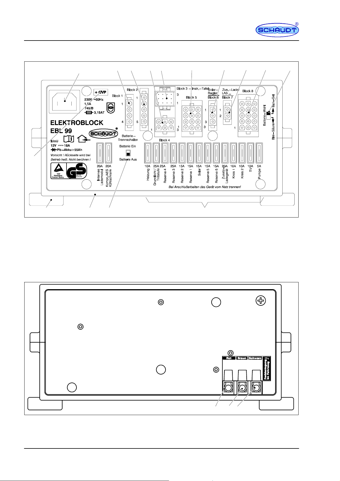
EDesign
1
23 45
15
14
Fig. 3 Layout of EBL 99 electrobloc (front)
13
12
1 Mains connector
2 Connection block, refrigerator
3 Connection block, refrigerator supply D+, battery sen-
sor/control lines
4 Connection block, frost protection valve, heating and
floor light/steps
5 Connection, IT ... / LT ... control and switch panel
6 Connection block, reserve
7 Connection block, solar regulator
6
7
8
9
11
8 Connection block, additional charger
9 Connection block TV, pump, consumers
10 Selector switch acid/gel battery
11 Flat veh icle fus e s
12 Battery cut-off switch
13 Housing
14 Assembly flaps
15 Sticker, + OVP (only for EBL 99 K with
OVP)
10
Fig. 4 Layout of EBL 99 electrobloc (rear)
1 Connection, living area battery
2 Connection, earth
12
Starter
Battery+NegativeBattery
Living area
-- +
123
3 Connection, starter battery
Date: 20.01.2010 811.419 BA / EN
Page 13
Instruction Manual for Electrobloc EBL 99 K / EBL 99 K with OVP
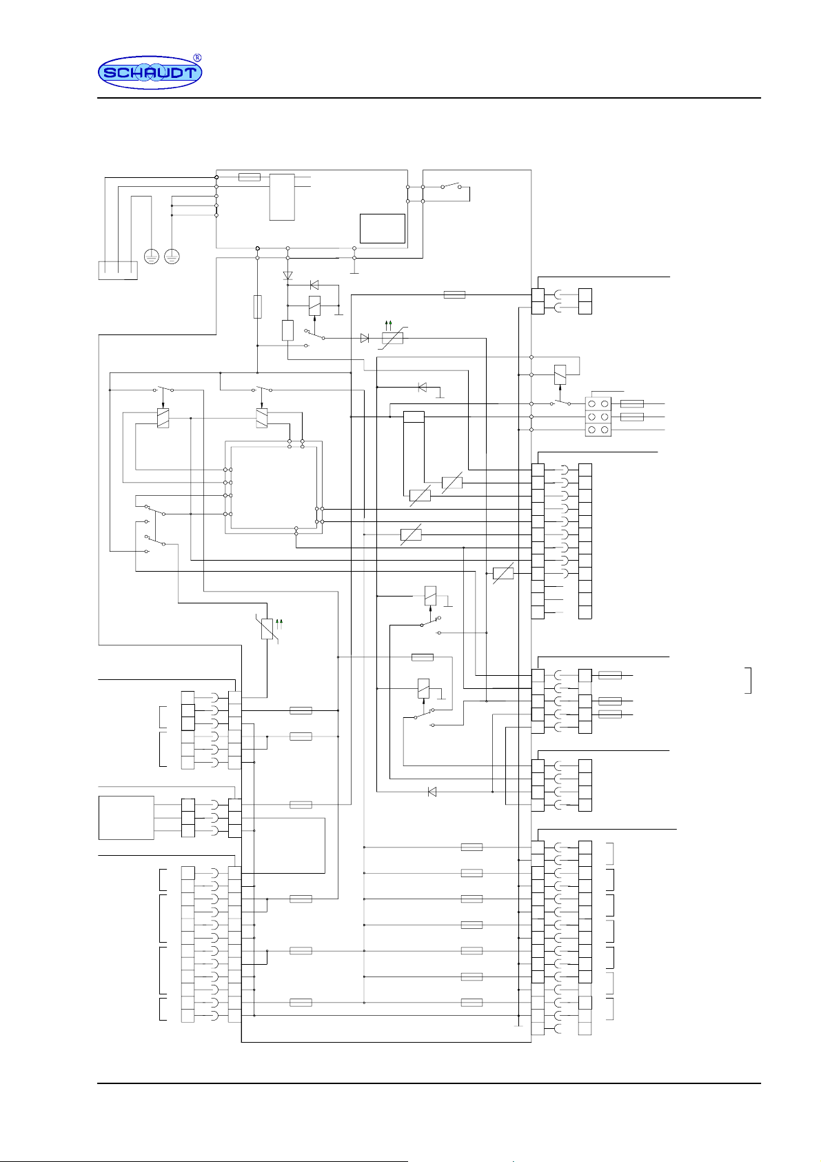
FBlockdiagram/connectiondiagram
Mains 230V~50Hz
Low power device socket
HS relay 60A
Battery
Cut--off switch
(off)
Cond. pl. KPL EBL 99--1
MNL socket cap 6F -- block 4
4
+
Heater
Floor light/
Step
MNL socket cap 3F -- block 6
Solar
charge
(E)
regulator
MNL socket cap 12F -- block 5
Solar cell
(only for LR 02)
Spare 4
Spare 3
Spare 2
*OnlyforEBL99KwithOVP
1
--
5
2
+
+
3
--
6
3
A
2
1
--
+
9
12
--
+
1
+
4
--
5
--
10
+
2
+
3
--
7
--
8
+
6
--
11
A1
A3
A11
A12
A2
Charging relay
A8
A9
A10
A4
12
10
11
OVP 01*
A8 A7 A9
+
A14
A13
20A
Starter battery
HS relay 60A
A5 A6
Module BW 99-- 2
771.461
A7
4Frost protection valve +
1
5
2
3
6
3
2
1
9
1
4
5
2
3
7
8
6
10A
25A
15A
max. 25A
max. 25A
max.15A max.15A
LASO 1218-- 6
A15
A11
A12
A14
A15
S1218--5
Refrigerator relay
Fridge
Relay
A17
A16
Selector switch
lead gel/
lead acid
Shunt
PolySwitch
PolySwitch
2.5A
20A
20A
2.5A
PolySwitch
2.5A
10A
10A
10A
max.15A
max.15A
PolySwitch
5A
MNL socket cap 2F block 7
22
11
Minus, living area battery must be connected externally to
Minus, starter battery.
A1
A2
A3
MR pin cap 12F block 3
6Mainsindicator
4
1
9
12
5
2
11
8
3
2.5A
7
10
MNL socket cap 5F -- block 2
5
2
1
3
4
MNL socket cap 4F -- block 1
4
1
2
3
MNL socket cap 15F -- block 8
6
12
9
14
2
8
3
10
7
13
4
11
1
5
+Auxiliary charger
Negative charger
Battery
cut--off relay
E20-- 3F
6
4Shuntbattery
1
Shunt consumer
9
12V ON
12V OFF
51212V indicator
Minus sensor living area battery (batt. 2)
2
11
+sensor,livingareabattery(batt.2)
8
+Starterbattery(Batt.1)
Not assigned
3
Not assigned
7
Not assigned
10
5
Negative, living area batt. sensor
2
1
3
4
Negative, starter battery for refrigerator*
4
+Compressor/AESrefrigerator
+Absorb.refrigerator*
1
2
D+ point
3
Negative, refrigerator
+
6
TV
12
--
9
+
Pump
14
--
+
2
Circuit 1
8
--
3
+
Circuit 2
--
10
7
+
Spare 1
13
--
4
+
Spare 5
11
--
+
1
Spare 6
--
5
Not assigned
1515
50A
+Starterbattery(Batt.1)
50A
+livingroombatt.(Batt.2)
Negative living area battery
*
Refrigerator lines are
to routed to battery poles isolated
from other battery
lines.
2A
+sensor,livingareabatt.
20A
+Starterbatt.forrefrigerator*
2A
D+ input
each 1.5mm
max. 10m
2
811.419 BA / EN
Date: 20.01.2010
13
Page 14

Instruction Manual for Electrobloc EBL 99 K / EBL 99 K with OVP
(blank page)
14
Date: 20.01.2010 811.419 BA / EN
 Loading...