


Instruction Manual
Electroblock EBL 101 D
EBL 101 C with OVP
Table of contents
1 Safety information 2......................................
1.1 Meaning of safety symbols 2...............................
1.2 General safety information 2...............................
2 Introduction 3............................................
3 Operation 3..............................................
3.1 Switching system on/off 3..................................
3.2 Changing the battery 4....................................
3.3 Operating faults 6........................................
3.4 Closing down the system 7................................
4 Application and functions in detail 8.........................
4.1 Battery functions 10........................................
4.2 Additional functions 1 1.....................................
4.3 Use as an exchange device 1 1..............................
5 Maintenance 1 1...........................................
Appendix 12..............................................
E Schaudt GmbH, Elektrotechnik und Apparatebau, Daimlerstraße 5, 88677 Markdorf, Germany, Tel. +49 7544 9577-0, Fax +49 7544 9577-29, www.schaudt--gmbh.de
811.554 BA / EN
Date: 29.04.2010
Instruction Manual EBL 101 D / EBL 101 C with OVP
1 Safety information
1.1 Meaning of the warning signs
Y
DANGER!
Failure to comply with this sign may result in danger to life and limb.
Y
WARNING!
Failure to comply with this sign may result in injury.
Y
A TTENTION!
Failure to comply with the sign may result in damage to equipment or other
connected consumers.
1.2 General safety instructions
The design of the device is state-of-the-art and complies with approved safety technology. Failure to observe the safety instructions may nonetheless
result in injury or damage to the device.
Only use the device when it is in perfect technical condition.
Faults impacting the safety of individuals or proper functioning of the device
must be rectified immediately by specialists.
Y
DANGER!
Parts carrying 230V.
Risk of fatal injury due to electric shock or fire:
F
Do not carry out maintenance or repair work on the device.
F
If cables or the device housing are damaged, do not use the device
and isolate it from the power supply.
F
Ensure that no liquids enter the device.
F
The mains connection line may only be replaced by an authorised customer service department or by qualified persons.
Y
WARNING!
Hot components!
Burns:
F
Only change blown fuses when the device is completely de-energised.
F
Blown fuses may only be replaced when the cause of the fault is
known and has been rectified.
F
Never bypass or repair fuses.
F
Only use original fuses rated as specified on the device.
F
Device parts can become hot during operation. Do not touch.
F
Never store heat sensitive objects close to the device (e.g. temperature sensitive clothes if the device has been installed in a wardrobe).
2
Date: 29.04.2010 811.554 BA / EN
Instruction Manual EBL 101 D / EBL 101 C with OVP
2 Introduction
This instruction manual contains important information for the safe operation
of equipment supplied by Schaudt. Make sure you read and follow the safety
instructions provided.
The instruction manual should always be kept in the vehicle. All safety information must be passed on to other users.
Y
This device is not intended to be used by persons (including children)
with limited physical, sensory or mental aptitude or lack of experience
and/or knowledge unless they are supervised by a person responsible for
their safety or have received instruction from this person on how the device is used.
Children are to be supervised so as to ensure they do not play with the
device.
This device is intended for installation into a vehicle.
3 Operation
The Electroblock is operated solely from the DT ... control and switch panel
connected (apart from battery isolation).
3.1 Switching system on/off
12V main switch
(on LT ... control and
switch panel)
Operation of the Electroblock is not required for daily use.
Initial settings are only required after the type of battery (lead-acid or leadgel) has been changed or during commissioning or when upgrading with accessories (see section 3.2 and EBL 101 D / EBL 101 C with OVP installation
instructions for details).
Y
A TTENTION!
Incorrect Electroblock settings.
Damage to connected devices. Therefore prior to starting:
F
Ensure the leisure area battery is connected.
F
Ensure that the battery selector switch (Fig. 1, Pos. 1) is set to the
correct position for the battery inserted.
F
Ensure that the AES fuse (Fig. 4, Pos. 16) is only inserted when an
AES refrigerator is connected. The leisure battery may totally discharge otherwise. Damage to the battery is possible.
Disable battery isolation on the Electroblock:
³ Move slide switch (see Fig. 4, Pos. 15) into position ”Battery ON”
811.554 BA / EN
³ After disabling the battery cut-off switch or after changing batteries: 12V
main switch on the DT ... control and switch panel must be turned on
briefly to start up the consumers.
Use the main 12V switch (see instruction manual of relevant control and
switch panel) to switch on/off all the consumers and the control and switch
panel.
Date: 29.04.2010
3
Instruction Manual EBL 101 D / EBL 101 C with OVP
Exceptions:
F
Heater
F
Step
F
Frost protection valve
F
AES/compressor refrigerator
F
Spare 4
For more information, see the DT ... control and switch panel instruction manual. .
Step switch
Operation with solar
regulator
The supply to the step is protected by a self-resetting fuse. This is why the
step switch may only be activated briefly.
Y
A TTENTION!
Activating the step switch too long results in too high a current.
Self-resetting fuse can activate:
F
Only press the step switch briefly.
³ If the self-resetting fuse has triggered, it needs about one minute to reset
before the step switch can be pressed again.
Y
A TTENTION!
No battery buffer function!
Damage to connected devices:
F
Do not operate solar regulator without battery connected.
Y
If an original Schaudt solar regulator is used, the solar current can be displayed on the control and display panel (e.g. DT ...). For this, the control
and display panel must be configured accordingly (a PIN is required).
Ask your dealer for advice.
3.2 Changing the battery
Y
A TTENTION!
Use of incorrect battery types or incorrectly rated batteries.
Damage to the battery or devices connected to the Electroblock:
F
Batteries should only be changed by experts.
F
Follow the battery manufacturer’s instructions.
F
Only connect the Electroblock to 12V power supplies with rechargeable 6-cell lead gel or lead acid batteries. Do not use any unsuitable
battery types.
Y
Normally only batteries of the same type and capacity should be used,
i.e. the same as those installed by the manufacturer.
4
Date: 29.04.2010 811.554 BA / EN
Changing the battery
Instruction Manual EBL 101 D / EBL 101 C with OVP
Y
It is possible to swap lead acid batteries with lead gel batteries. Changing
from lead gel batteries to lead acid batteries is not possible without overhead. Contact the vehicle manufacturer for more information.
³ Disconnect the battery from the Electroblock by activating the battery iso-
lation on the DT ... control and switch panel (see also section 3.4).
³ Remove the ”+ solar cell” connector on the solar charge regulator (if avai-
lable).
³ Isolate the Electroblock from the mains voltage (230V AC).
³ Replace the battery.
³ After changing the battery, recheck which type of battery has been inserted.
Y
DANGER!
Incorrect setting of the battery selector switch.
Risk of explosion due to build up of explosive gases:
F
Move the battery selector switch to the correct position.
Y
A TTENTION!
Incorrect setting of the battery selector switch.
Damage to the battery.
F
Move the battery selector switch to the correct position.
³ Disconnect the Electroblock from the mains before adjusting the battery
selector switch.
Y
When using AGM batteries, moving the battery selector switch to the
”Lead Gel” position is recommended. Experience tells us that AGM batteries are charged perfectly this way.
Starting up
the system
However, suitability must be checked on a case-by-case basis using the
specifications from the battery manufacturer and the charging parameters of the Electroblock.
The charging parameters are specified in Appendix ”Technical details”
(Section E).
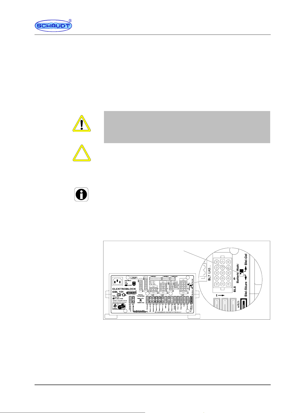
1
Fig. 1 Battery selector switch
³ Move the battery selector switch (Fig. 1, Pos. 1) to the correct position
using a thin object (such as a ballpoint pen):
F
Lead gel battery: Move the battery selector switch to ”Lead-gel”.
F
Lead acid battery: Move the battery selector switch to ”Lead-acid”.
³ Plug in the ”+ solar cell” connector on the solar charge regulator (if avai-
lable).
³ Start up the system as described in section 3.1.
811.554 BA / EN
Date: 29.04.2010
5

Instruction Manual EBL 101 D / EBL 101 C with OVP
ggp
t
lybelow1
3.3V)Havethemainsvoltag
e
Starterbatteryisnotchar
NomainsvoltageSwitchontheautomati
c
g
y
operation(batteryvoltag
e
g
p
3.3 Faults
Flat vehicle fuses
Self-resettingfuses
A fault in the power supply system is usually caused by a blown fuse.
The following functions are protected by self-resetting fuses:
F
Exit step
F
Sensor lines to the DT ... control and switch panel
If there is a fault with the step, it must not be operated for a period of 1 minute. The fuse resets automatically during this period.
For faults with the DT ... control and switch panel, the entire system must be
switched off from the battery cut-off and turned on again after about 1 minute.
Please contact our customer service department if you cannot rectify the
fault using the following table.
If this is not possible, e.g. if you are abroad, you can have the Electroblock
repaired at a specialist workshop. In this case, you must ensure that the
warranty is not invalidated by incorrect repairs being carried out. Schaudt
GmbH shall not accept any liability for damage resulting from such repairs.
Fault Possible cause Remedy
Living area battery is not
charged during 230V operation (battery voltage
constan
Living area battery is overcharged during 230V operation (battery voltage
constantly above 14.5 V)
Starter battery is not char- No mains voltage Switch on the automatic
ged during 230V operation (battery voltage constantly below 13.0 V)
Living area battery is not
charged during mobile
below 13.0 V)
The living area battery is
overcharged during mobile operation (battery voltage constantly above
14.3 V)
The refrigerator does not
work during mobile operation
No mains voltage Switch on the automatic
fuse in the vehicle
Have the mains voltage
checked
Defective Electroblock Call customer service
Defective Electroblock Call customer service
fuse in the vehicle
Have the mains voltage
checked
Defective Electroblock Call customer service
Defective alternator Check the alternator
No voltage on D+ input Check fuses and wiring
Defective Electroblock Call customer service
Defective alternator Check the alternator
No power supply to the refrigerator
Defective Electroblock Call customer service
Defective refrigerator Check the refrigerator
Check fuse and wiring
6
Date: 29.04.2010 811.554 BA / EN

Instruction Manual EBL 101 D / EBL 101 C with OVP
g
)
Solarchargeregulatornot
Pluginsolarchargeregu
Def
C
heck
f
p
ply
12Vsupplydoesnotwor
k
12Vmainswitchfortheli
12Vmainswitchfortheli
ggy
g
y
D
T
d
D
T
d
Def
C
heck
f
beoperatedfromtheDT
Fault RemedyPossible cause
Solar charger does not
work (power supply and
engine are off)
12V su
in the living area
The Electroblock cannot
be operated from the DT
... control and switch panel
does not work 12Vmain switchfor the li- 12V main switchfor the li-
Solar panel in (partial)
shade or covered (snow or
dirt)
Solar charge regulator not Plug in solar charge reguplugged in
ectivefuse or wiring
Solar charge regulator defective
ving area battery is switched off
Activate battery isolation
on the
switch panel
Defective Electroblock Call customer service
Defective Electroblock Call customer service
... controlan
ectivefuse or wiring
Move solar panel out of
shade or clean.
lator
use andwiring
Check solar charge regulator
ving area battery must be
switched on
Activate battery isolation
on the
switch panel
... controlan
use andwiring
Y
The charging current is reduced automatically if the device becomes too
hot due to excessive ambient temperature or lack of ventilation. Always
prevent the device from overheating nevertheless.
Y
If the automatic shutdown mechanism of the battery monitor is triggered,
fully charge the living area battery.
3.4 Closing down the system
Y
A TTENTION!
Total discharge.
Damage to the living area battery:
F
Fully charge the living area battery before and after closing down the
system. Connect a vehicle with an 80 Ah battery and a vehicle with a
160 Ah battery to the mains for at least 12 and 24 hours respectively.
Y
A TTENTION!
Permitted input voltages exceeded.
Damage to connected consumers:
F
Do not operate any connected Schaudt solar charge regulator without
battery.
F
When the battery is changed or removed, first unplug the ”+ solar cell”
connector on the solar charge regulator.
811.554 BA / EN
Date: 29.04.2010
7

Instruction Manual EBL 101 D / EBL 101 C with OVP
Shutdown of system up
to 6 months
Disconnect the living
area battery from the
12V on-board supply
³ Fully charge the living area battery before closing down the system.
The living area battery is then protected against total discharge. This only
applies if the battery is intact. Follow the battery manufacturer’s instructions.
Once shut down, the system requires approx. 4 Ah per month.
Disconnect the living area battery from the 12V power supply if the motorhome is not used for a longer period (during the winter for example). For
this, the system has a battery cut-off mechanism that isolates the living area
battery from the vehicle. Battery isolation is activated from the DT ... control
and switch panel (see DT ... control and switch panel instruction manual).
³ 12V main switch on the DT ... control and switch panel must be switched
off.
³ Move battery cut-off switch (sliding switch, see Fig. 4, Pos. 15) to posi-
tion ”Battery OFF”.
The battery cut-off switch isolates the following connections from the living
area battery:
F
12V consumers
F
Frost protection valve
F
Control and switch panel
Y
The living area battery can also be charged using the internal charger
module, an auxiliary battery charging unit, the solar charge regulator and
the alternator when the battery cut-off switch is switched off.
Shutdown period longer
than 6 months
Only EBL 101 C with OVP:
Overvoltage protection
OVP
³ Fully charge the living area battery before closing down the system.
³ Remove the ”+ solar cell” connector on the solar charge regulator.
³ Remove the clamps from the battery terminals.
Y
The battery alarm is no longer active.
Y
The frost protection valve opens for certain heater systems when the living area battery is isolated from the Electroblock via the battery cut-off.
The boiler and water tank empty when the frost protection valve is open.
See the instruction manual for the heater system for further information.
4 Application and functions in detail
Y
This device is intended solely for installation in a vehicle.
The Electroblock is the central energy supply device for all 12 V consumers
in the electrical system on board the motorhome/caravan. It is normally located inside a cupboard or storage area and is accessible from the front for
fuse changes.
Electroblock EBL 101 C with OVP is suitable for all applications posing a
particular risk of overvoltage, such as lightning strikes hitting the national
grid, generator operation, poor electronic installations or trips to distance
countries.
For this, an overvoltage protection unit is fitted in Electroblock EBL 101 C
with OVP between the mains connection and the charge module.
8
Date: 29.04.2010 811.554 BA / EN

Instruction Manual EBL 101 D / EBL 101 C with OVP
Modules
Solar regulator
LR / LRS ...
(accessory)
230V AC
+--
Starter battery
+--
Living area battery
Fig. 2 On-board power supply system
Electroblock EBL 101 D contains:
F
a charge module for charging all connected batteries
Control and
display panel
DT/LT ...
Electroblock
EBL 101 D
EBL 101 C with OVP
Additional charger
LAS ...
(accessory)
Lighting
Pump
Heater
etc.
12V consumers
System devices
Protective circuits
F
the entire12 V distribution system
F
fuses for the 12V circuits
F
a main switch module
F
other control and monitoring functions
Electroblock EBL 101 C with OVP contains in addition:
F
overvoltage protection OVP
A DT ... control and switch panel must be connected for operation. This device controls the electrical functions in the motorhome’s living area as well
as the accessories.
There are connections for an additional battery charger and a solar charge
regulator.
Flat vehicle fuses protect the various circuits. Exceptions here are the step
and the frost protection valve.
F
Excess temperature
F
Overload
F
Short circuit
F
Overvoltage in the 230 V supply (only EBL 101 C with OVP)
Mains connection
811.554 BA / EN
Current-carrying
capacity
230 V AC ± 10 %, 47 to 63 Hz sinusoidal, protection class I
12V outputs may be loaded with max. 90% of the rated current of the respective fuse (see also installation instructions or front panel).
Date: 29.04.2010
9

Instruction Manual EBL 101 D / EBL 101 C with OVP
4.1 Battery functions
Suitable batteries
Battery charging
whilst moving
Battery isolation
Battery selector switch
Battery monitor with
automatic disconnect
6-cell lead acid or lead gel batteries, 55 Ah and above
Simultaneous charging of the starter battery and the living area battery via
the alternator, parallel connection of the batteries via a cut-off relay
The battery cut-off (at the battery cut-off switch of the Electroblock, see Fig.
4, Pos. 15, see also section 3.4) isolates the following connections from the
living area battery:
F
all 12 V consumers
F
the frost protection valve
This prevents slow discharge of the living area battery by the standby current during shutdown of the vehicle (discharge with approx. 4 Ah in month).
The batteries can still be charged using the Electroblock, the alternator, an
auxiliary charging unit or the solar charge regulator, even when the battery
cut-off switch is switched off.
The switching option provided by the battery selector switch ensures optimum charging of the two battery types, lead gel and lead acid.
The battery monitor of the DT ... control and switch panel constantly monitors the living area battery with dynamic voltage threshold. The cut-off point
is ”earlier” for lower discharge currents than for larger currents. This provides improved total discharge protection. Monitoring is also performed in the
switched-off state. A warning message is displayed below 12.0 V (dependent on current drain).
If the voltage of the living area battery sinks further, falling below 10.5V , the
battery monitor immediately switches off all 12V consumers. The control and
display panel also switches itself off. Only the frost protection valve continues to be powered (so it stays closed). Before switch-off, all switch states
and the value of the battery capacity are stored and restored after power-on.
If an overload or an insufficiently charged living area battery causes the voltage to fall so low that the automatic disconnector is triggered, any non-essential consumers should be switched off.
If need be, the 12V supply can begin operation for a short time. In this case
the 12 V main switch on the DT ... control and switch panel must be switched on.
However, if the battery voltage remains below 11.0 V, the 12 V power supply
can not be turned back on.
Fully charge the living area battery as soon as possible. For more information, see the ”Battery voltages” description in the relevant DT ... control and
switch panel instruction manual.
10
Date: 29.04.2010 811.554 BA / EN

Instruction Manual EBL 101 D / EBL 101 C with OVP
4.2 Additional functions
Automatic switch
function for
AES/compressor
refrigerator
Step fuse
Battery charging with
solar charging regulator
4.3 Use as an exchange device
This relay supplies the AES/compressor refrigerator with power from the
starter battery when the vehicle engine is running and the D+ connection is
live. An AES/compressor refrigerator is powered by the living area battery
when the vehicle engine is not running.
The step output is protected by a self-resetting 15A fuse.
If a fault occurs, such as overcurrent, the self-resetting fuse interrupts the
relevant circuit.
After rectification of the fault, the fuse automatically resets after approx. 1
minute.
Maximum permitted charge current 14 A, protected with 15 A
Depending on the solar charge regulator used, either only the living area
battery is charged or the living area battery and the starter battery.
Electroblocks EBL 101 D and EBL 101 C with OVP can be used as exchange devices for the EBL 100. The plug-and-socket connections of the old
device can all be used.
Some additional functions and plug connections of the EBL101 will however
remain without a function.
Cleaning
5 Maintenance
The Electroblock requires no maintenance.
Clean the Electroblock with a soft, slightly damp cloth and mild detergent.
Never use spirit, thinners or similar substances. Do not allow liquids to enter
the Electroblock.
811.554 BA / EN
E
No part of this manual may be reproduced, translated or copied without express written permission.
Date: 29.04.2010
11

Instruction Manual EBL 101 D / EBL 101 C with OVP
Appendix
A EC declaration of conformity
Schaudt GmbH hereby confirms that the design of Electroblocks EBL 101 D
and EBL 101 C with OVP complies with the following relevant regulations:
-- DIRECTIVE 2006/95/EC OF THE EUROPEAN PARLIAMENT AND
COUNCIL from 12.12.2006 for the harmonisation of the legal provisions of member states in regard to electrical equipment for use within
particular voltage limits
-- DIRECTIVE 2004/108/EC OF THE EUROPEAN PARLIAMENT AND
COUNCIL from 15.12.2004 for the harmonisation of the legal provisions of member states in regard to electromagnetic compatibility and
for the annulment of directive 89/336/EEC
-- Law on the electromagnetic compatibility of equipment from February
26th 2008
Manufacturer
Address
B Special fittings/accessories
Switch panel
Additional charger
Solar charge regulator
C Customer service
Customer service
address
Schaudt GmbH, Elektrotechnik & Apparatebau
Daimlerstrasse 5
88677 Markdorf
Germany
Schaudt DT ... switch panel (required for operation)
Schaudt battery charger LAS ... with max. 18 A charge current, including
suitable connection cable (MNL).
Schaudt Solar charge regulator, type LR ... (or LRS ... ; required if the solar
current is to be displayed) for solar modules with an overall current of 14 A
with 3-pin connector and connector cable (LRS ... with 2 connectors)
Schaudt GmbH, Elektrotechnik & Apparatebau
Daimlerstrasse 5
D-88677 Markdorf
Phone: +49 7544 9577-16 Email: kundendienst@schaudt-gmbh.de
12
Send in device
Office hours Mon to Thurs 08.00 -- 12.00, 13.00 -- 16.00
Fri 08.00 -- 12.00
Returning a faulty device:
³ Complete and enclose the fault report, see Appendix D.
³ Send it to the addressee (delivery free).
Date: 29.04.2010 811.554 BA / EN

Instruction Manual EBL 101 D / EBL 101 C with OVP
D Fault report
In the event of damage, please complete the fault report and send it together with the faulty device to the manufacturer.
Device type: _______________________
Item no.: _______________________
Vehicle: Manufacturer: _______________________
Model: _______________________
Own installation? Yes - No Upgrade? Yes - No -
Following fault has occurred (please tick):
- Electrical consumers do not work -- which?
(please specify below)
- Switching on and off not possible
- Persistent fault
- Intermittent fault/loose contact
Other remarks:
Mains connection
Current consumption
Standby current from
Living area battery
D+ loading
Current-carrying
capacity
811.554 BA / EN
E Technical details
230 V AC ± 10 %, 47 to 63 Hz sinusoidal, protection class I
1.9 A
Depending on the control and switch panel: approx. 5 -- 20 mA, plus consumption of controller electronics of refrigerator
Measurement approx. 10 minutes after disconnection from the mains:
F
not connected to mains
F
12.6 V battery voltage
F
Battery isolation not enabled
F
Control and switch panel lighting off
F
12V main switch off
Loading of D+ output of the alternator by the Electroblock approx. 200 mA
without current consumption on D+ point
12V outputs A maximum of 90% of the nominal
current of the relevant fuse may be
drawn.
Date: 29.04.2010
13

Instruction Manual EBL 101 D / EBL 101 C with OVP
Frost protection valve output max. 0.1 A
D+ point max 1 A
Battery charging, living
area battery with mains
connection
Characteristic charging curve IUoU
Final charging voltage 14.3 V
Charge current 18 A in the entire mains voltage range,
electronically limited, minus the
charge current into the vehicle battery
Voltage for float charge 13.8 V with automatic switchover
New charge cycle, with battery voltage below 13.8 V
Switchover to main charging with a few seconds delay
Solar
charging
V
Main charge
I
14.3
13.8
Fig. 3 Example of the charging voltage curve with the Electroblock
Full charge
Uo
4hwithleadacid
16 h with lead gel
Float charge
U
Tim e
I Main charge with maximum 18 A charging current, electronically limi-
ted, up to final charging voltage. Start of charge also for totally discharged batteries.
Uo Automatic changeover to full charge with constant 14.3 V. The duration
of the fully charge phase depends on the type of battery and can be
adjusted at the device:
Battery charging, starter
battery with mains
connection
Battery charging via
solar charge regulator
Battery charging
whilst moving
Battery monitor
U Automatic changeover to trickle charge with constant 13.8V. In the
trickle charge phase, the voltage at the output of the charging module
is constant.
Start of a new charging cycle by switching over to main charge, if the battery
voltage falls below 13.8 V for more than 5 seconds when loaded. Start of
charge also for totally discharged batteries. The internal charge module can
also be operated without living area battery.
For mains operation, the starter battery is also charged (with maximum
charge current of 6 A).
Maximum permitted charge current 14 A, protected with 15 A;
Depending on the solar charge regulator used, either only the living area
battery is charged or the living area battery and the starter battery.
Simultaneous loading of living area battery by alternator
Batteries connected in parallel via a cut-off relay
Switch-off voltage: dynamic,
controlled by control and switch panel
Minimum battery voltage for approx. 1 1.0 V
Switch-on via the
12Vmainswitchonthe
control and switch panel:
14
Date: 29.04.2010 811.554 BA / EN

F Layout
Instruction Manual EBL 101 D / EBL 101 C with OVP
1
*(
23 4 5
16171819 15
Fig. 4 Layout of Electroblock EBL 101 D / EBL 101 C with OVP (front); *(+OVP label only for EBL 101 C with OVP)
1 Mains connector
2 Connection block, refrigerator supply
3 Connector block, refrigerator supply D+,
Battery sensor/control lines
4 Connector block, heating, floor light, step
5 Connector, DT ... control and switch panel
6 Connector, DT ... control and switch panel
7 Connection block, solar regulator (measurement signal)
8 Connection block, reserve
9 Connection block, solar regulator (supply)
10 Connection block, additional charger
1 1 Connection block TV, pump, consumers
12 Selector switch acid/gel battery
13 Self resetting step fuse (internal)
14 Flat vehicle fuses, consumers
15 Battery cut-off switch
16 AES refrigerator fuse
17 Flat vehicle fuse, internal charger module
18 Housing
19 Assembly flaps
67 8129
14
10
11
13
Fig. 5 Layout of Electroblock EBL 101 D / EBL 101 C with OVP (rear)
1 Connection, living area battery
2 Connection, earth
811.554 BA / EN
Date: 29.04.2010
123
3 Connection, starter battery
15

Instruction Manual EBL 101 D / EBL 101 C with OVP
G Block diagram/wiring diagram
Charging relay
for starter battery
Lead-gel/
lead-acid
switchover
Battery
cut--off switch
(off)
Power supply
switching stage
Refrigerator
relay
Fuse only with
compressor/AES
refrigerator.
Prise appareil de froid
∼
secteur 230 V
Pin rail MSFQ/0 4F-BL10to
LR ... solar regulator
Solar
charge
regulator
LR ...
MNL-bush socket 3F-BL6 on
LR ... solar regulator
MNL-bush socket 6F-BL4
Frost protection valve
MNL-bush socket 12F-BL5
50 Hz
MS * relay 60
A
Circuit board
WB signal
SB signal
[+]WB
SB
[ -- ] Negative
Solar module
[Solar module]
Heater
Floor light
/Step
OVP*
MS * relay 60
A
Module HS100
Only for EBL 101 C with OVPOVP*:
MNL-bush socket 2F-BL7 on additional LAS ... charger
Negative charging unit
+ Auxiliary charging unit
Battery
cut--off relay
Pin rail MSFQ/0 12F-BL3to DT ... digital panel
Pin rail MSFQ/0 7F-BL9to DT ... digital panel
MNL-bush socket 5F-BL2
MNL-bush socket 4F-BL1
MNL-bush socket 5F-BL8
The negative pole of the living
battery must be connected externally
the negative pole of the starter
+ Starter battery (Batt. 1)
+ living room batt. (Batt. 2)
Negative living area battery
Mains indicator
Shunt battery
Shunt consumer
MS relay 1 On
MS relay 1 Off
Minus sensor living area battery (batt. 2)
MS relay 2 On
MS relay 2 Off
Negative lighting
+ Lighting
+ sensor living area battery (batt. 2)
+ Starter battery (Batt.1)
D+ point
Signal solar living area battery
Signal solar starter battery
nc
* Refrigerator lines must be lead to
nc
the battery poles without being
nc
connected to other battery supplies
nc
+ sensor living area battery
Negative sensor living area battery
+ Starter batt. for refrigerator*
D+ input
Negative starter battery for refrigerator*
+ Compressor/AES refrigerator
+ Absorber refrigerator*
D+ point
Negative refrigerator
D+ point
TV
area
battery
every 1.5 mm
max. 10 m
to
2
16
Spare 4B
Spare 4A
Spare 3
Spare 2
Pump
Circuit 1
Circuit 2
Spare 1
Spare 5
Spare 6
Date: 29.04.2010 811.554 BA / EN
 Loading...