

Page 1
© 2005 Schaudt GmbH, Elektrotechnik & Apparatebau, Daimlerstraße 5, 88677 Markdorf, Germany, Phone +49 7544 9577-0, Telefax+4975449577-29, www.schaudt-gmbh.de
SDT-0018-02EN (Valid from software version 2.16) 830.563 Situation: 18.07.2005
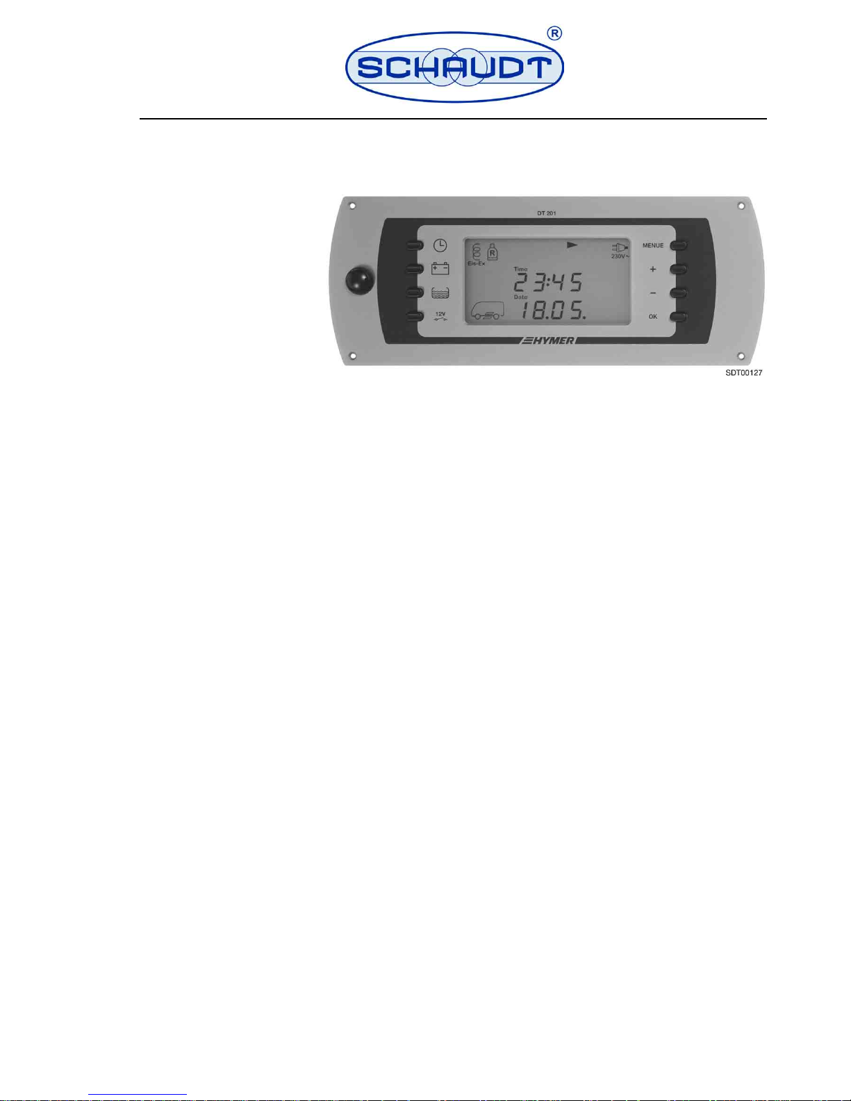
0 Instruction Manual Control and Switch Panel DT 201 B
Instruction manual
Control and switch panel DT 201 B
Table of contents
1 Introduction . . . . . . . . . . . . . . . . . . . . . . . . . . . . . . . . . . . . . . . . . .2
2 Safety information . . . . . . . . . . . . . . . . . . . . . . . . . . . . . . . . . . . . .2
3 Description and appropriate use . . . . . . . . . . . . . . . . . . . . . . . . . .3
4 Technical data . . . . . . . . . . . . . . . . . . . . . . . . . . . . . . . . . . . . . . . .4
5 Operation . . . . . . . . . . . . . . . . . . . . . . . . . . . . . . . . . . . . . . . . . . . .5
6 Starting up . . . . . . . . . . . . . . . . . . . . . . . . . . . . . . . . . . . . . . . . . .19
7 Maintenance. . . . . . . . . . . . . . . . . . . . . . . . . . . . . . . . . . . . . . . . .20
8 Shutting down . . . . . . . . . . . . . . . . . . . . . . . . . . . . . . . . . . . . . . .20
9 Technical faults, possible causes and remedies . . . . . . . . . . . . .21
10 Circuit diagram - for specialist workshop only . . . . . . . . . . . . . . .22
11 Customer service . . . . . . . . . . . . . . . . . . . . . . . . . . . . . . . . . . . . .23
12 Fault report. . . . . . . . . . . . . . . . . . . . . . . . . . . . . . . . . . . . . . . . . .24
Page 2
2 Situation: 18.07.2005 SDT-0018-02EN
Instruction Manual Control and Switch Panel DT 201 B
1 Introduction
This instruction manual contains important information for the safe operation
of the control and switch panel. It is essential to read and to follow the given
safety information.
The instruction manual should always be kept in the motorhome/caravan. All
safety information must be passed on to other users.
The reproduction, translation and duplication of this manual, even in parts, is
not allowed without written authorization.
2 Safety information
The design of the control and switch panel is state-of-the-art and according to
approved safety technology regulations. Nevertheless, if the safety information in this instruction manual is not closely followed, persons might be injured
or the control and switch panel might be damaged.
Do not use the control and switch panel if it is not in technically good order
and condition. The instruction manual must be followed.
Any technical faults affecting the safety of persons or of the control and switch
panel must be dealt with immediately by qualified personnel.
W
Failure to comply with this sign may lead to the endangerment of persons.
W
Failure to comply with this sign may damage the unit or the connected consumers.
W
This sign indicates recom men dati on s or sp ecial feat ures .
W
The electrical system of the motorhome or the caravan has to meet current DIN, VDE and ISO regulations. Manipulations of the electrical system will endanger the safety of persons and the vehicle, and are therefore prohibited.
W
Never make any modifications to the control and switch panel.
W
Connection work is to be carried out in tensionless condition only.
W
The electrical connection may only be established by qualified personnel and must be carried out according to the Schaudt installation
instructions.
W
If the living area battery is totally discharged or overcharged for a lengthy
period, it will be irreparably damaged.
W
Switch off the 12 V main switch when you leave the vehicle. This prevents
the living area battery from unnecessarily discharging.
W
Before starting to drive, check if the step and the supports are retracted
and if the roof hood is closed. If the sensors are defective or if the D+ signal
is missing, the warning signal can fail.
Page 3
SDT-0018-02EN Situation: 18.07.2005 3
Instruction Manual Control and Switch Panel DT 201 B
3 Description and appropriate use
The job of the control and switch panel DT 201 B is to control the electrical
functions in the living area of the motorhome and display various values such
as capacity, voltages, battery currents and water tank levels.
This system includes:
P
An Electrobloc, consisting of a charger module, the 12 V distribution and
the fuses for each circuit
P
Tank sensors for measuring the level in the water tanks
P
An outside temperature sensor
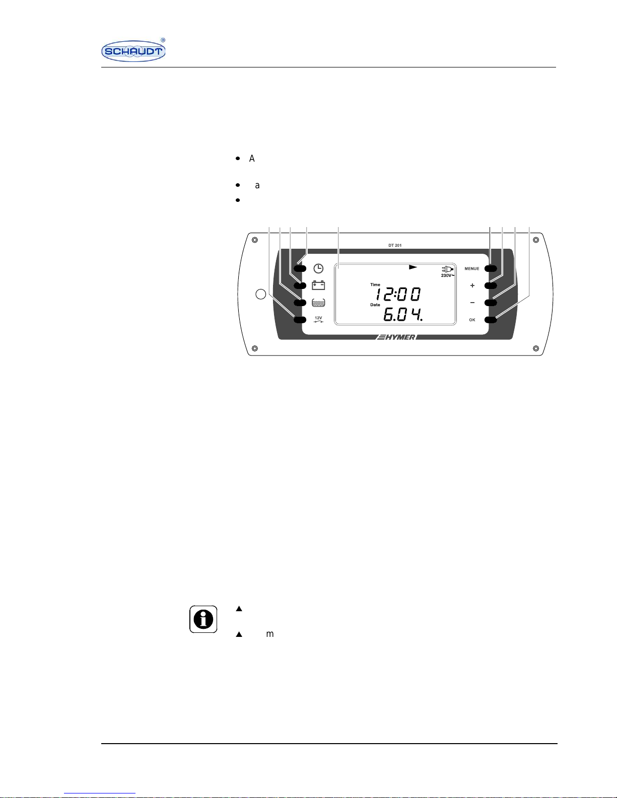
Fig. 1 Control and switch panel DT 201 B
1 12 V main switch button
2 Tank button
3 Battery button
4 Basic display button
5 Display window
6 "MENUE" button, setting menu
7 "+" button (increase indicated value)
8 "–" button (reduce indicated value)
9 "OK" button (selection/confirm settings)
Buttons The various displays and menus are selected and settings made using the
8 buttons on the front of the control and switch panel.
The control and switch panel must first be switched on using the 12 V main
switch button, before the other buttons can be used. When the control and
switch panel is switched on, the basic display is visible.
If the basic display, tank or battery button is pressed, the corresponding display appears and is illuminated. 20 seconds after pressing the button for the
last time, the basic display appears. It is not illuminated.
The "MENUE" button must be pressed for more than 3 seconds to arrive at
the desired setting menu.
1
23
4
5
6
987
SDT0009
2
W
The control and switch panel can only be switched on, if the living area battery voltage is above 11.0 V.
W
For more information, see the section 5.7.
Page 4
4 Situation: 18.07.2005 SDT-0018-02EN
Instruction Manual Control and Switch Panel DT 201 B
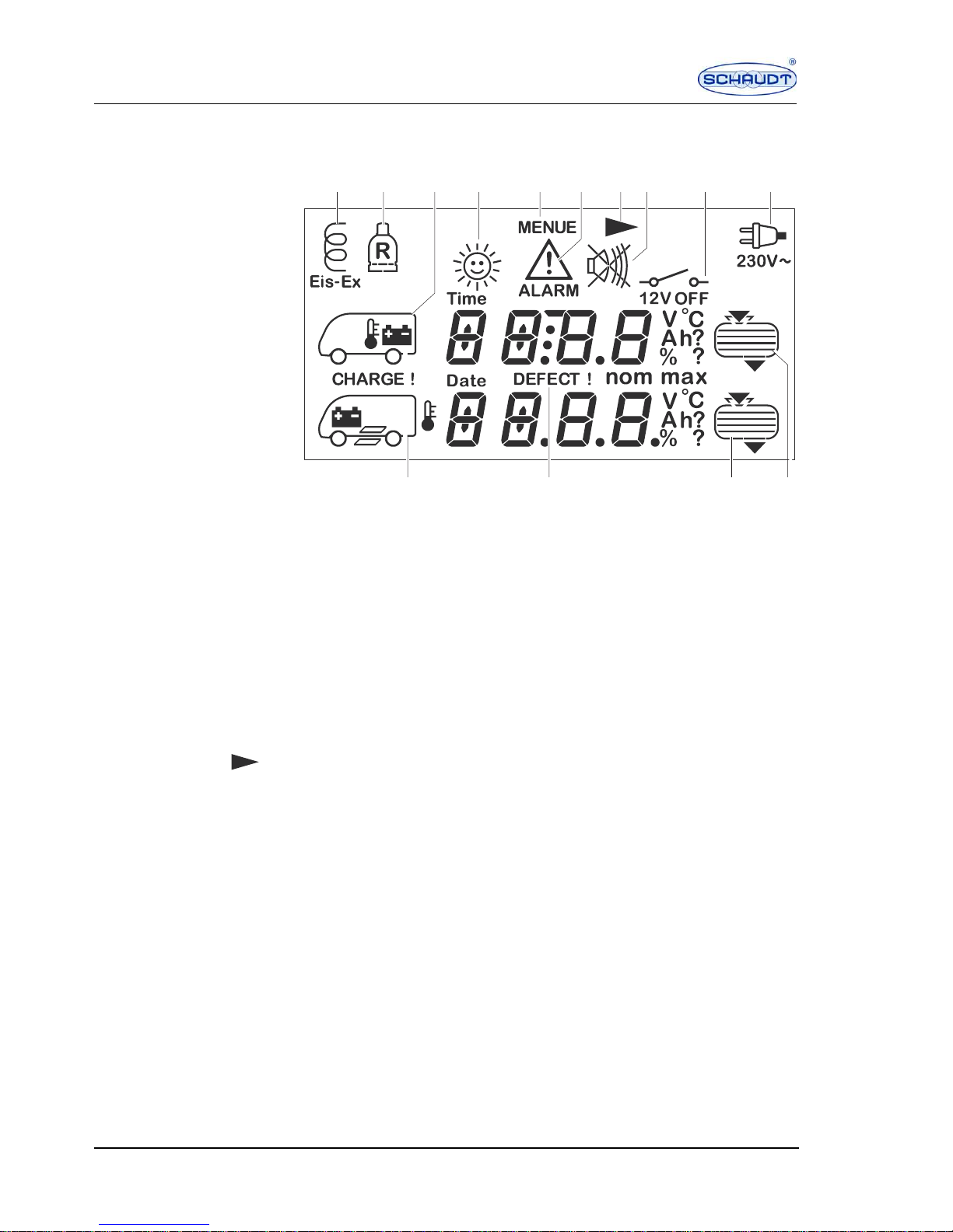
Symbols on the display Symbols, meas ured va lues an d setti ngs of th e selec ted di splay ar e indica ted
in the display window.
Fig. 2 Display window
1 Defroster switched on
2 Spare cylinder in use
3 Living area battery/inside temperature
4 Solar current
5 Setting menu
6 Battery and filling level alarm
7 Call up next page
8 Optical display for buzzer/warning that buzzer is switched off
9 12 V Off display (3 seconds)
10 230 V power supply is connected
11 Water tank
12 Waste water tank
13 Fault display for battery, filling level sensors, temperature sensors
14 Starter battery/outside temperature/step
Calling up the next page If the arrow is visible in the display window, the next page can be called up
with the basic display, tank, battery and menu buttons.
4 Technical data
Operating voltage 12 V (10 - 14.5 V), powered via Electrobloc
S
DT00094
21
14
1213
10
9
11
456378
Page 5
SDT-0018-02EN Situation: 18.07.2005 5
Instruction Manual Control and Switch Panel DT 201 B
5 Operation
5.1 Switching the 12 V power supply for the living area
on and off
12 V main switch button The 12 V main switch button switches all consumers and the control and
switch panel on and off.
Exceptions:
P
Floor light/step
P
Frost protection valve
P
Heater
P
Spare 4
P
Compressor refrigerator/AES refrigerator
Switching on
Press the 12 V main switch button. The illuminated basic display appears
and the system is ready for use. The basic display is illuminated for
20 seconds. If there is an alarm message, this is also indicated in the basic
display.
Switching off
Press the 12 V main switch button. The system shuts down. The text "12 V
OFF" appears for 3 seconds.
5.2 Using the basic display
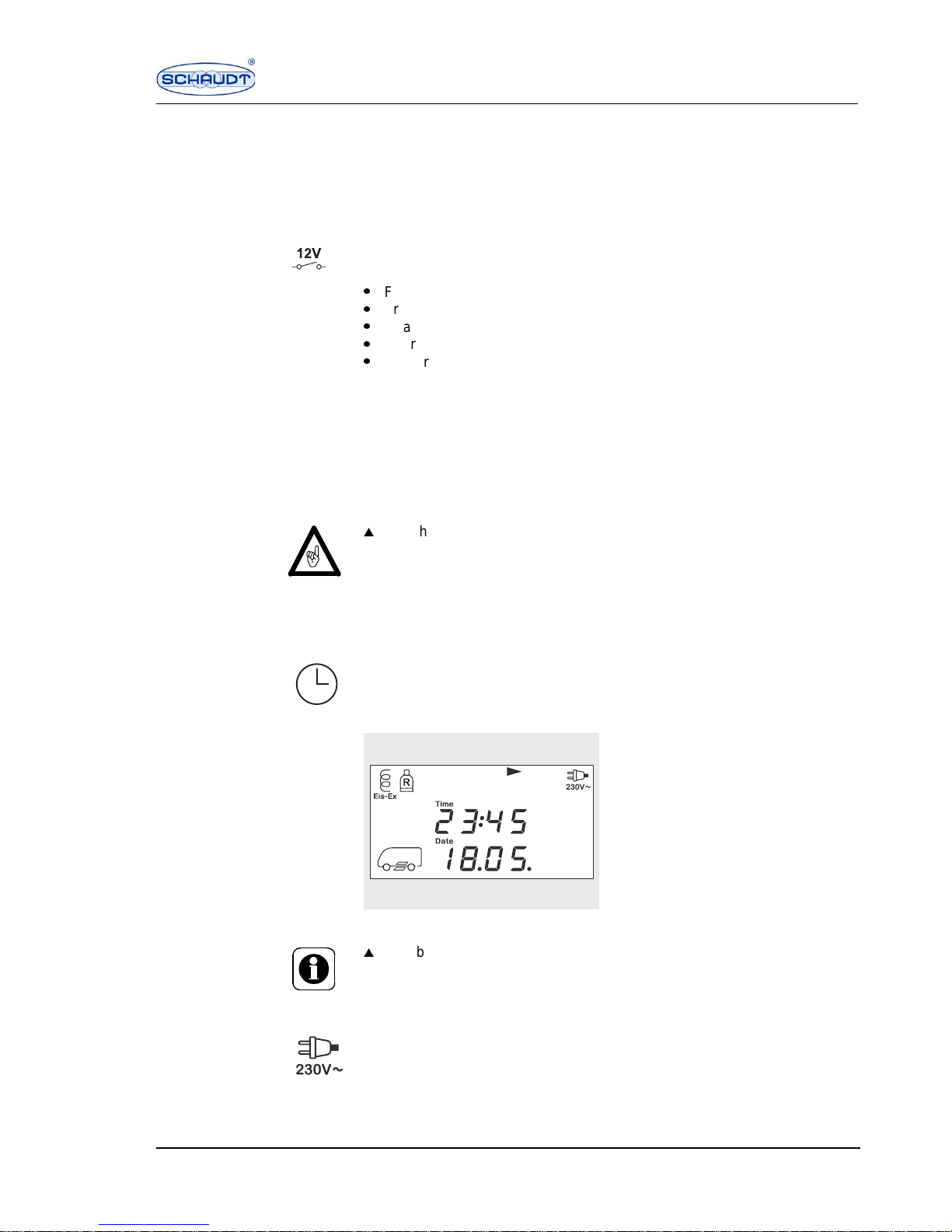
Basic display button The basic display gives information on mains indicator, step, special equip-
ment and temperature as well as date and time.
Press basic display button.
The 1st page of the basic display appears.
Fig. 3 Basic display
230 V mains indicator The 230 V mains indicator symbol is displayed, if the input of the Electrobloc
is live and if the control and switch panel has been switched on using the 12 V
main switch.
W
Switch off the 12 V main switch when you leave the vehicle. This prevents
the living area battery from unnecessarily discharging.
SDT0009
5
W
If no button is pressed for 20 seconds, the system automatically switches
back to the basic display that is not illuminated.
Page 6
6 Situation: 18.07.2005 SDT-0018-02EN
Instruction Manual Control and Switch Panel DT 201 B
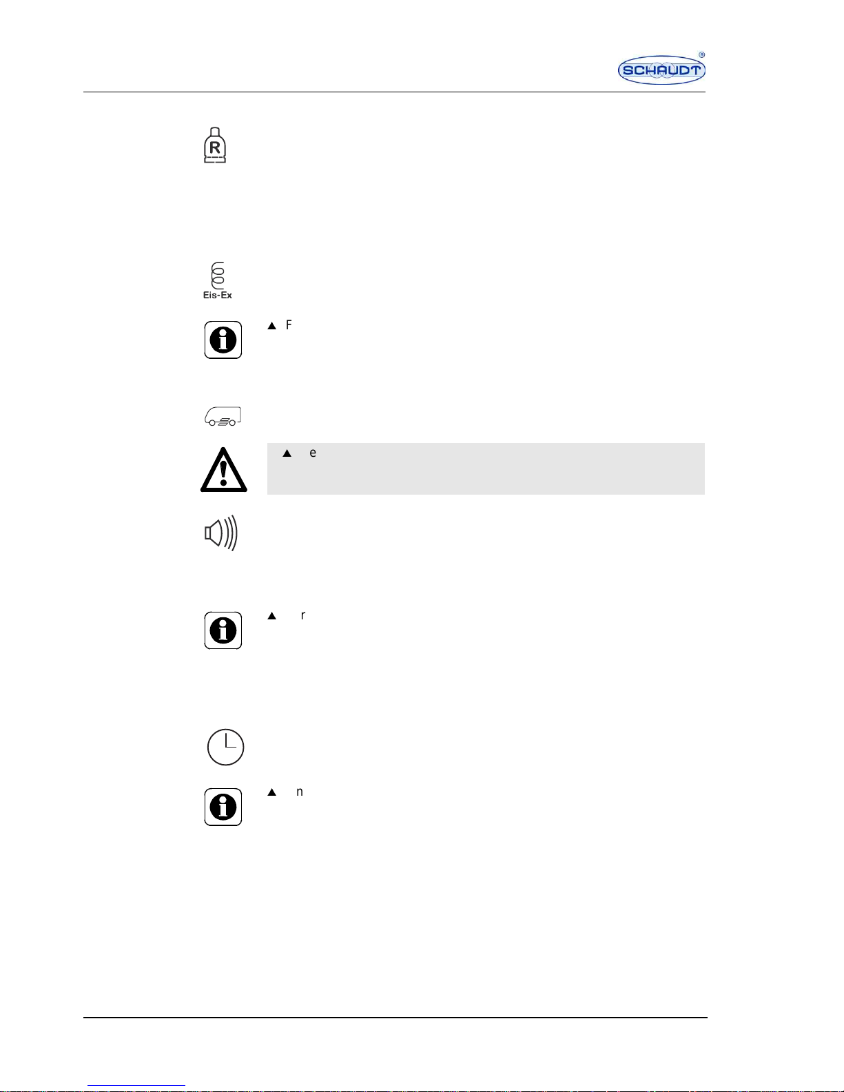
Spare cylinder (optional) For additional equipment Truma Duomatic L plus:
The spare cylinder symbol is displayed when one of the two gas cylinders is
empty.
The spare cylinder symbol flashes if the second gas cylinder is also empty.
The "ALARM" message appears in the basic display.
For additional equipment Truma Triomatic:
The spare cylinder symbol is displayed when the gas cylinder in use is empty.
Defroster (optional) For additional equipment Truma Duomatic L or Truma Triomatic:
The "Eis-Ex" (defroster) symbol is displayed when the defroster unit is
switched on.
Step The step symbol is displayed when the step is extended.
Before commencing the journey, the step must be retracted.
If the step is extended and the engine is started, a loud warning signal is emitted and the buzzer symbol appears on the display.
If the sensors are defective or if the D+ signal is missing, the warning signal
can fail. Before commencing the journey, the driver must therefore check if
the step is retracted.
5.2.1 Checking the temperatures
Basic display button Press the basic display button twice briefly.
The inside and outside temperatures are indicated on the 2nd page of the
basic display. The display range is between -40 °C and +60 °C.
W
For more information, see the instruction manual for the additional equipment.
W
Before commencing the journey, check if the step is retracted.
W
For more information, see the sectio n 5.7.
W
If no button is pressed for 20 seconds, the system automatically switches
back to the basic display that is not illuminated.
Page 7
SDT-0018-02EN Situation: 18.07.2005 7
Instruction Manual Control and Switch Panel DT 201 B
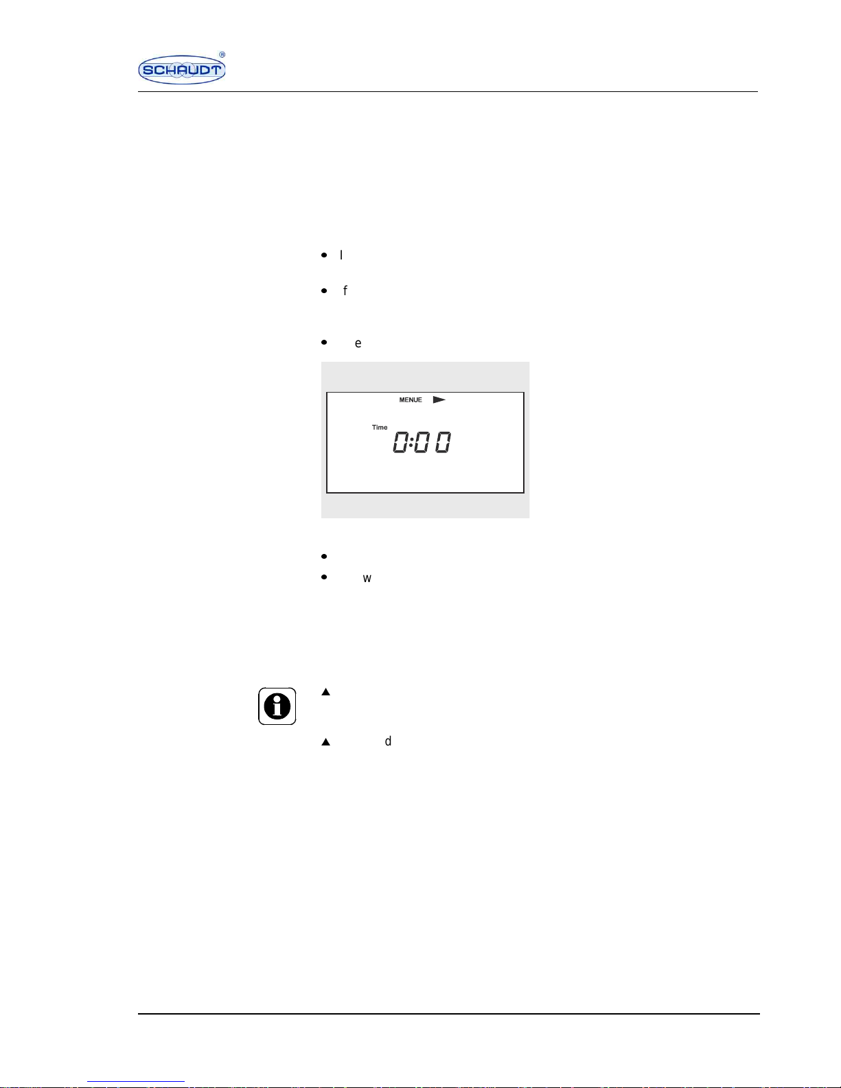
5.2.2 Settings in the basic menu
The defroste r option can b e switched on an d off in the bas ic menu. Tim e, date
and nominal battery capacity can also be set and software version and
parameter number displayed.
"MENUE" button
In the basic display, press the "MENUE" button for more than 3 seconds.
The 1st page of the basic display appears. The adjustable values flash in
the display.
P
If the step alarm is emitted, it can be switched off on the 1st page (page is
only visible if the warning signal is emitted).
P
If the defroster unit is installed, the defroster option can be switched on
and off on the next page (page is only visible if the defroster unit is
installed).
P
The time can be set on the next page.
Fig. 4 Basic menu
P
The date can be set on the next page.
P
Software version and parameter number are displayed on the next page.
Change the flashing value with the "+" or "–" button.
Press "OK" button.
The entry of the new value is confirmed, the next adjustable value begins
to flash and can be changed or confirmed.
Press "MENUE" button.
The next page is displayed.
To exit the menu, press any button or wait for 20 seconds until the display
automatically switches to the basic display.
SDT0009
8
W
If no button is pressed for 20 seconds, the system automatically switches
back to the basic display that is not illuminated. Entries that are not confirmed with "OK" are not saved.
W
Changed values are only saved if the entry was confirmed using the "OK"
button.
If one switches to another display before pressing the "OK" button, the
changed values are not saved.
Page 8
8 Situation: 18.07.2005 SDT-0018-02EN
Instruction Manual Control and Switch Panel DT 201 B
Defroster unit The defroster unit can be switched on and off or set to automatic operation in
the basic menu. Depending on the setting, "ON", "OFF" or "AUTO" is indicated in the display window. This menu is only displayed if the defroster unit is
installed.
In automatic operation, the defroster unit is automatically switched on if the
outside temperature falls below +7.5 °C and automatically switched off if the
temperature rises above +7.5 °C.
Setting th e time
Press the "MENUE" button for more than 3 seconds.
The basic display is displayed.
Press the "MENUE" button several times until the "TIME" page of the basic
menu is displayed. The hour display flashes.
Set the hours with the "+" or "–" button.
Press "OK" button.
The hour entry is confirmed. The minute display flashes.
Set the minutes with the "+" or "–" button.
Press "OK" button.
The minute entry is confirmed. The time is set.
Setting the date
Press the "MENUE" button several times until the "DATE" page of the
basic menu is displayed. The year display flashes.
Set the year with the "+" or "–" button.
Press "OK" button.
The entry of the year is confirmed. The day display flashes.
Set the day with the "+" or "–" button.
Press "OK" button.
The entry of the day is confirmed. The month display flashes.
Set the month with the "+" or "–" button.
Press "OK" button.
The entry of the month is confirmed.
Software version and
parameter number
Press the "MENUE" button several times until the software version and the
four-digit parameter number are displayed. These settings cannot be
changed.
To exit the menu, press any button or wait for 20 seconds until the display
automatically switches to the basic display.
Press "OK" button.
W
Both defroster outputs are designed only for operation with the liquid gas
control units Truma Duomatic L plus or Truma Triomatic and may only be
used together with these units. The maximum load current for each output
is 0.4 A.
W
Software version and parameter number are required for queries at the
dealer or customer service. Always have these settings ready for queries.
W
For the correct functionality, the parameter number must be modified if
special equipment is installed at a later date. You can obtain further information at your dealer or at Schaudt GmbH customer service.
Page 9

SDT-0018-02EN Situation: 18.07.2005 9
Instruction Manual Control and Switch Panel DT 201 B
5.3 Battery display
The battery display indicates the battery capacity and the load current of the
living area battery as well as the battery voltage of living area battery and
starter battery. If available, the solar current of living area battery and starter
battery is also displayed.
The control and switch panel is equipped with a real level display for the living
area battery. The display of the battery capacity gives direct information on
how much power is stored in the battery.
Example: The battery has been fully charged (100 %) and the motorhome has
not been connected to a 230 V power supply for 3 days. The display indicates
40 %. That means that the battery can supply the motorhome with power for
about 2 more days.
Other functions The following functions are also integrated:
P
Automatic setting of the capacity display to "full" on reaching a full battery
charge
P
Warning if the battery capacity falls below 15 % of the nominal level. For
more information see section 5.3.5
P
Automatic determination of the maximum possible battery capacity (in Ah)
for defined discharging of the battery
P
Warning at the end of the battery service life (max. capacity reached: only
50 % of the nominal capacity)
P
Charge request if the last full charge was more than 20 days ago
P
Setting of the nominal capacity by the motorhome user (e.g. if a higher battery capacity is retrofitted)
5.3.1 Checking battery capacity and load current
Battery button Press battery butto n.
Battery capacity and charge current of the living area battery appear on
the 1st page of the battery display.
Fig. 5 Battery display
SDT0009
7
Page 10
10 Situation: 18.07.2005 SDT-0018-02EN
Instruction Manual Control and Switch Panel DT 201 B
The battery capacity can be displayed in ampere hours (Ah) and percent (%).
Switching between units
Press "OK" button.
The display of the battery capacity switches between the units ampere
hours (Ah) and percent (%).
The charging current of the living area battery is shown in amps (A).
Positive values indicate the charging current. Negative values indicate the
discharge current.
The battery display takes all types of battery charge into account in connection with the Electrobloc EBL 101:
P
Via the charger module of the 230 V mains
P
Via the cut-off relay of the alternator while driving
P
Via a solar charge regulator for the solar cells connected to the system
5.3.2 Checking the battery voltage
Battery button Press battery button twice briefly.
The voltages of living area battery and starter battery appear on the 2nd
page of the battery display.
Voltage in the living area battery
Voltage in the starter battery
The off-load voltage of the starter battery is only displayed if the engine is
switched off and if no consumers are using the starter battery.
W
The illumination of the display requires approx. 0.4 A. This illumination cur-
rent is added to the discharge current and displayed.
W
In order to register the entire power consumption, all consumers must be
connected to the Electrobloc. If consumers are connected directly to the
battery, the Schaudt system cannot register their power consumption. The
indication of current, battery capacity and charge request are not correct
in such an event.
W
If no button is pressed for 20 seconds, the system automatically switches
back to the basic display that is not illuminated. Entries that are not con-
firmed are not saved.
W
In mobile operation, the voltage of the starter battery is indicated slightly
too low, if the refrigerator is in use with 12 V. If the refrigerator is switched
off or operated using gas, the voltage display of the starter battery is cor-
rect. In stationary operation, the voltage of the starter battery is also dis-
played correctly.
Page 11
SDT-0018-02EN Situation: 18.07.2005 11
Instruction Manual Control and Switch Panel DT 201 B
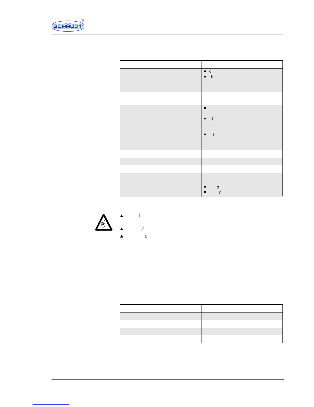
The following table will help you correctly interpret the living area battery voltages displayed by the control and switch panel. These values apply to actual
operation, not off-load voltage and for lead gel batteries only.
1)
depending on the current load
Checking the condition of
the battery
Measuring the off-load voltage is an additional method of assessing the condition of the battery. Off-load voltage is the voltage of the charged battery in
a passive state, with no current being supplied or drawn.
Take the measurement several hours after the last charging. In the meantime,
no significant load should have been placed on the battery, which means no
current should have been drawn from it. If the off-load voltage of the battery
is less than 12.0 V, there is a risk of total discharge.
The following table will help you interpret the off-load voltage displayed.
These values apply for lead gel batteries.
Battery voltage Description
10.5 or less
P
Risk of total discharge
P
The battery monitor switches off all
consumers (apart from the frost
protection valve)
11 V or more The 12 V power supply ca n be switched
on using the main switch
10.5 V to 12 V
P
If the voltage falls below 12 V, the
battery alarm is triggered
P
If the voltage remains under
10.5-12 V
1)
for more than 1 minute,
the battery capacity is set to zero
P
If the voltage remains under
10.5-12 V
1)
for more than 5minutes,
the system is switched off
12 V to 13.2 V Battery off load
More than 13.2 V Battery is being charged: Main charge
13.8 V constant Trickle charge voltage
14.3 V Final charging voltage (equalising
charge)
P
1 h for lead acid battery
P
8 h for lead gel battery
W
If the living area battery is totally discharged or overcharged for a lengthy
period, it will be irreparably damaged.
W
If the 12 V power supply is overloaded, switch off some of the consumers.
W
Inactive consumers can gr adua lly dis c har ge the batter y.
Values for off-load voltage Charging condition of the battery
12 V 0 %
12.2 V 25 %
12.3 V 50 %
More than 12.8 V Full
Page 12
12 Situation: 18.07.2005 SDT-0018-02EN
Instruction Manual Control and Switch Panel DT 201 B
Charge request
CHARGE !
The batteries should be fully charged every 4 weeks for a long service life.
As a reminder a charge request is displayed 20 days after the last equalising
charge.
Connect the motorhome to the 230 V power supply.
The batteries are charged.
5.3.3 Displaying the solar current (optional)
Battery button The solar current display is only possible with a solar charge regulator type
LRS... of Schaudt GmbH.
Press battery button three times briefly.
The solar currents of living area battery and starter battery appear on the
3rd page of the battery menu:
Solar current display of the living area battery
Solar current display of the starter battery
To exit the display, press any button or wait for 20 seconds until the dis-
play automatically switches to the basic display.
5.3.4 Displaying the maximum battery capacity of the living
area battery
The maximum battery capacity of the living area battery "Ah max" is displayed
in the battery menu, but it cannot be set. The maximum capacity is set at the
factory to 80 % of the nominal capacity. The control and switch panel also
recalculates the battery capacity after every complete charging cycle (total
charge and total discharge) and indicates the current value. This display
applies only to the living area battery.
Press battery button once briefly.
Press the "MENUE" button for more than 3 seconds.
The maximum battery capacity "Ah max" of the living area battery appears
on the 1st page of the battery menu.
To exit the menu, press any button or wait for 20 seconds until the display
automatically switches to the basic display.
W
For more information see section 5.7 as well as the instruction manual for
the Electrobloc.
W
For more information, see the sectio n 5.7.
Page 13

SDT-0018-02EN Situation: 18.07.2005 13
Instruction Manual Control and Switch Panel DT 201 B
5.3.5 Settings in the battery menu
Displaying/setting the
battery capacity
The nominal battery capacity "Ah nom" can be adapted e.g. on retrofitting a
battery. The setting range is between 50 Ah and 495 Ah (K100 value). The
standard setting ex works is 90 Ah.
Press battery button once briefly.
Press the "MENUE" button for more than 3 seconds.
The 1st page of the battery menu is displayed. The maximum battery
capacity "Ah max" is displayed.
Press "MENUE" button a second time.
The 2nd page of the battery menu is displayed. The display of the battery
capacity flashes.
Enter the new battery capacity of the living area battery with the "+" or "–"
button. It can be read off at the battery as K value. If no K100 value is indicated, the K20 value can be read off and multiplied by 1.125.
Confirm the set value with the "OK" button.
To exit the menu, press any button or wait for 20 seconds until the display
automatically switches to the basic display.
5.4 Battery monitor
Automatic disconnector The battery monitor compares the living area battery voltage to a reference
voltage. Monitoring is continued, even when the control and switch panel is
switched off.
Depending on the current drain an alarm message is displayed or the system
is shut down sooner or later. This improves protection against total discharge
of the battery.
As soon as the battery voltage falls below 10.5 V to 12 V (depending on the
discharge current), an alarm message appears in the display window. As
soon as the battery voltage falls below 10.5 V, all 12 V consumers are immediately switched off. Only the frost protection valve is still powered. The control and switch panel also shuts down. Before shutting down, all switching
conditions and the battery capacity value are saved. The automatic disconnector is not triggered by short-term low voltage, caused by high current when
switching on consumers.
If an overload or an insufficiently charged living area battery causes the voltage to fall so low that the automatic disconnector is triggered, any consumers
which are not essential should be switched off.
You may be able to switch on the 12 V power supply for a short time.
Press the 12 V main switch button.
The 12 V power supply is switched on.
W
Changed values are only saved if the entry was confirmed using the "OK"
button.
If one switches to another display before pressing the "OK" button, the
changed values are not saved.
W
If no button is pressed for 20 seconds, the system automatically switches
back to the basic display that is not illuminated.
Page 14

14 Situation: 18.07.2005 SDT-0018-02EN
Instruction Manual Control and Switch Panel DT 201 B
If the battery voltage remains below 11.0 V, you cannot switch on the 12 V
power supply. The battery symbol and "CHARGE !" flash. The battery voltage
is also displayed.
Fully charge up the living area battery as soon as possible.
5.5 Tank display
The tank level can be indicated and the tank alarm switched on and off in the
tank display.
5.5.1 Checking the tank level
Tank button Press tank button.
Fig. 6 Tank display
The tank level is indicated as a numerical value in steps of 0 %, 25 %, 50 %,
75 % and 100 % and also as graphical symbol with 1 to 4 filling level marks.
Filling level of the water tank
Filling level of the waste water tank
W
The saved switching conditions and the battery capacity value are
restored on switching the unit on.
W
For more information, see the section 5.7 and the table "Battery voltage".
SDT00096
Page 15
SDT-0018-02EN Situation: 18.07.2005 15
Instruction Manual Control and Switch Panel DT 201 B
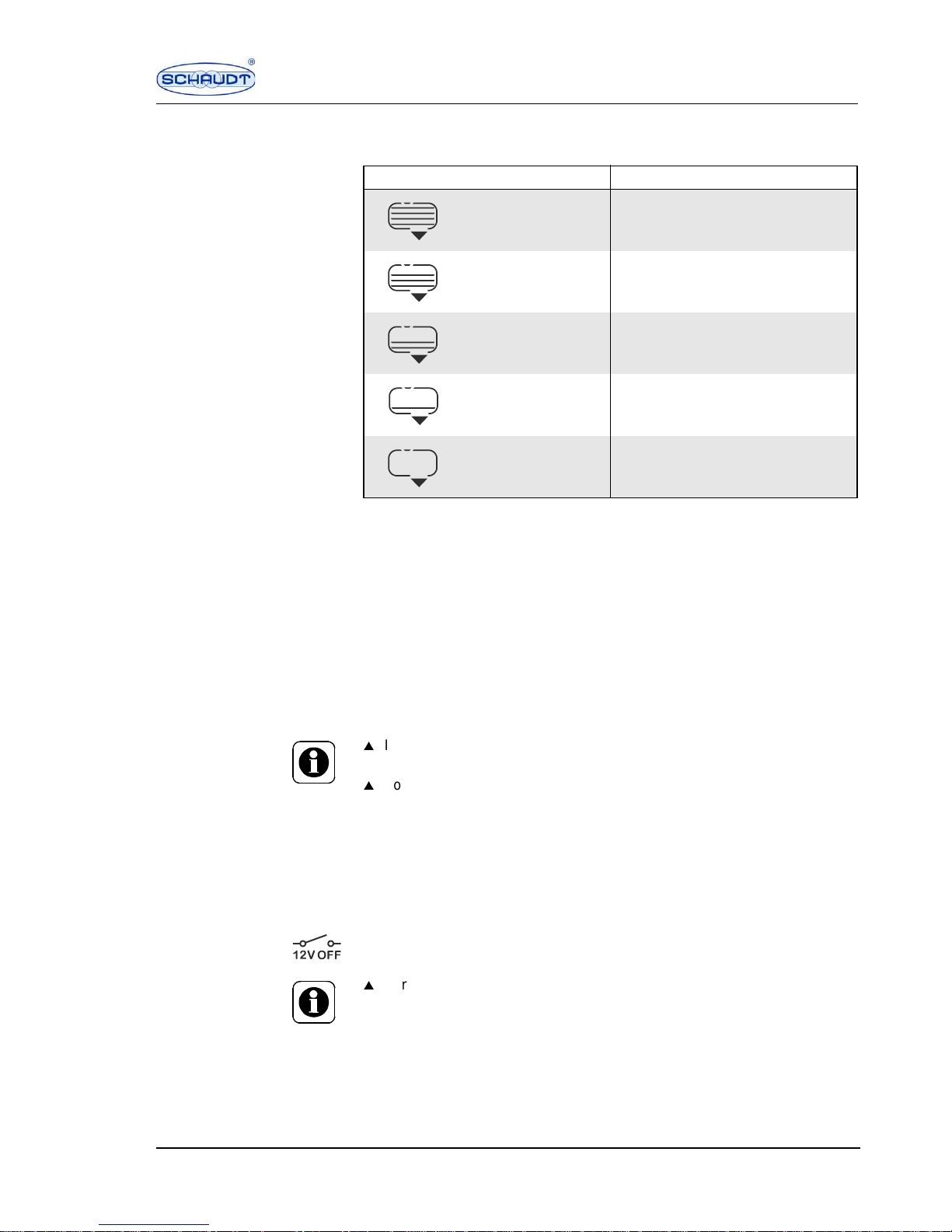
The following table will help you correctly interpret the tank levels indicated by
the symbols.
5.5.2 Settings in the tank menu
Tank alarm The tank alarm can be switched on and off in the tank menu.
In the tank display, press the "MENUE" button for more than 3 seconds.
The tank menu is displayed.
Switch the tank alarm on or off with the "+" or "–" button.
When the tank alarm is switched on, "ON" appears in the display window.
When the tank alarm is switched off, "OFF" appears.
Press "OK" button.
The entry is confirmed.
5.6 Tank monitor
The tank monitor checks the water tank and waste water tank levels. This
check is carried out every minute or on switching to the tank display. As soon
as the water tank is empty or the waste water tank is full, the tank alarm is
triggered.
The water tank is not monitored if the 12 V power supply of the consumers is
switched off and while driving.
Symbol on display Tank level
Full or almost full
Roughly 3/4 full
Roughly 1/2 full
Roughly 1/4 full
Empty or almost empty
W
If no button is pressed for 20 seconds, the system automatically switches
back to the basic display that is not illuminated.
W
For more information, see the section 5.7.
W
For more information, see the section 5.7.
Page 16

16 Situation: 18.07.2005 SDT-0018-02EN
Instruction Manual Control and Switch Panel DT 201 B
5.7 Alarm messages
Alarm messages are indicated in the basic display by a flashing warning triangle and the corresponding symbol. In addition, the display window lights up
for 20 seconds. More information on the alarm message is displayed in the
battery menu and tank menu.
If there are multiple alarm messages, they are indicated simultaneously with
the corresponding symbols.
5.7.1 Livin g area battery alarm
The battery alarm is triggered if the living area battery is nearly totally discharged or if the battery exceeds its gassing limit during the charging process
due to overvoltage (U
batt
> approx. 14.6 V).
Total discharge If the living area battery voltage falls below the critical limit of 12 V to 10.5 V
(depending on the current drain), the warning triangle and the word "ALARM"
flash in the basic display.
The living area battery symbol and the charge request "CHARGE !" also flash.
Switch off all consumers.
Recharge the living area battery by driving or by connecting it to the 230 V
mains.
Overvoltage If there is overvoltage and therefore a risk of the living area battery falling
below its gassing limit (U
batt
> approx. 14.6 V), the warning triangle and the
word "ALARM" flash in the basic display.
The living area battery symbol and the charge request "CHARGE !" also flash.
The battery voltage value flashes in the display.
Interrupt the charging of the battery, disconnect the battery from the 230 V
power supply.
Call customer service.
W
If the living area battery is totally discharged for a lengthy period, it will be
irreparably damaged.
W
If the voltage is too high, the living area battery will be irreparably damaged.
W
If the battery is empty, the control and switch panel cannot be switched on.
As soon as the 12 V main switch button is pressed, the charge request
"CHARGE !" and the battery symbol flash. The motorhome symbol and the
battery voltage are also indicated.
W
For more information see section 5.4, the table "Battery charge" as well as
the instruction manual for the Electrobloc.
W
For more information see section 5.4, the table "Battery charge" as well as
the instruction manual for the Electrobloc.
Page 17

SDT-0018-02EN Situation: 18.07.2005 17
Instruction Manual Control and Switch Panel DT 201 B
5.7.2 Battery capacity alarm for the living area battery
CHARGE ! The battery capacity alarm is triggered when the capacity of the living area
battery falls below 15 % of the nominal capacity.
The motorhome symbol is indicated in the basic display with a flashing battery
symbol. The battery display also indicates the battery capacity and the charge
request "CHARGE !".
Recharge the living area battery by driving or by connecting it to the 230 V
mains.
5.7.3 Charge request (instruction)
CHARGE !
DATE
The motorhome symbol is indicated in the basic display with a flashing battery
symbol 20 days after the last equalising charge.
The battery menu also displays the charge request "CHARGE !", the word
"DATE" and the battery capacity.
The battery should be fully charged every 4 weeks for 24 hours to maintain its
full capacity.
Fully charge the living area battery by driving or by connecting it to the
230 V mains.
5.7.4 Battery defect message for the living area battery
DEFECT Batteries lose their capacity due to ageing and wear.
The battery defect message is displayed as soon as the maximum capacity
falls below 50 % of the preset nominal capacity "Ah
nom
". The motorhome
symbol with a flashing battery symbol and the message "DEFECT" are indicated in the basic display. The living area battery has reached its maximum
service life.
Check the battery and install a new living area battery, if required.
5.7.5 Message for undefined battery capacity
If the charge status of the battery is not known (e.g. after starting up the system for the first time or after changing the batteries), a "?" is displayed as
capacity value. In addition, the charge request "CHARGE !" is displayed.
Recharge the living area battery by connecting it to the 230 V mains for at
least 24 hours.
After completion of the charging process, disconnect the battery from the
mains.
Push any button.
After approx. 30 seconds the "?" disappears.
W
For more information see the instruction manual for the Electrobloc.
Page 18

18 Situation: 18.07.2005 SDT-0018-02EN
Instruction Manual Control and Switch Panel DT 201 B
5.7.6 Tank alarm
If the water tank level falls below 12 % or if the waste water tank level exceeds
87 %, the warning triangle, the word "ALARM" and the tank symbol flash in
the basic display.
The tank symbol and the tank level percentage indicator also flash in the tank
display.
Fill up water tank or drain waste water tank.
5.7.7 Step alarm
Before commencing the journey, the step must be retracted. If the step is not
retracted, a loud warning signal is emitted and the buzzer symbol appears on
the display when the engine is started.
If the sensors are defective or if the D+ signal is missing, the warning signal
can fail. Before commencing the journey, the driver must therefore check if
the step is retracted.
False step alarm In exceptional cases, there can be a false alarm: The step alarm is triggered,
even though the step is retracted.
If such a malfunction occurs, the acoustic warning signal can be switched off
after starting the engine.
In the basic display, press the "MENUE" button for more than 3 seconds.
Set the buzzer to "OFF" with the "+" or "–" button of the basic menu.
Confirm the entry with "OK".
To exit the menu, press any button or wait for 20 seconds until the display
automatically switches to the basic display.
Have the malfunction rectified by the dealer.
5.7.8 Mains alarm
If the 230 V power supply fails or if it is disconnected from the motorhome, the
230 V symbol flashes.
As soon as the 230 V power supply has been restored, the symbol lights up
and remains illuminated.
The symbol goes out as soon as the engine is started.
Switching off the flashing
symbol
Press "OK" button.
The mains alarm is confirmed. The symbol goes out.
W
If the water tank remains empty due to an external water supply, the tank
alarm can be switched off.
W
For more information, see the sectio n 5.5.
W
Before commencing the journey, check if the step is retracted.
W
The acoustic warning signal must be switched off after every engine start,
until the malfunction has been rectified.
Page 19

SDT-0018-02EN Situation: 18.07.2005 19
Instruction Manual Control and Switch Panel DT 201 B
5.7.9 Gas alarm
For additional equipment Truma Duomatic L plus: If one of the two gas cylinders is empty, the spare cylinder symbol appears in the basic display. As soon
as the second gas cylinder is empty, the spare cylinder symbol and the
"ALARM" message appear.
5.7.10 Tank sensor fault message
If there is a malfunction of the water or waste water sensors, a "?" flashes in
the tank display.
Clean the tank sensors of the respective tank.
If the fault message is still displayed after cleaning, customer service must be
informed.
5.7.11 Temperature fault message
If there is a malfunction of the temperature sensors or if a temperature is not
within the range of between -40 °C and +60 °C, a "?" is indicated in the temperature display.
5.7.12 Date message
DATE If no date has been entered in the basic menu, the word "DATE" flashes. The
date display is required for the capacity display to work properly.
6 Starting up
The control and switch panel DT 201 B can only be started up with the Electrobloc EBL 101 and the accessories for measuring the water tank levels.
Starting up the system
Set the battery cut-off switch on the Electrobloc to "Batterie Ein" (battery
on). Follow the instruction manual of the Electrobloc.
Press the 12 V main switch on the control and switch panel.
After shutting down If the battery is disconnected from the system (battery cut-off switch is turned
off on the Electrobloc or a battery pole is disconnected): Check the off-load
voltage of the battery immediately after start up. Do not connect the vehicle
to the 230 V mains, do not start the engine and do not switch on any consumers until the off-load voltage of the battery has been checked.
After an off-load time of maximum 6 months, the battery voltage should be
above 12.7 V if the battery was fully charged before shut down. If voltage is
below 12.0 V then the battery might be defective and need to be replaced.
W
After switching on the battery cut-off switch or after changing batteries:
Switch on the 12 V main switch on the control and switch panel briefly to
start up the consumers.
W
Connection work is to be carried out in tensionless condition only.
Page 20

20 Situation: 18.07.2005 SDT-0018-02EN
Instruction Manual Control and Switch Panel DT 201 B
7 Maintenance
The control and switch panel requires no maintenance.
Cleaning Clean the front plate of the control and switch panel with a soft, slightly damp
cloth and a mild detergent.
Never use spirit, thinners or similar substances.
Do not allow any fluid to penetrate the inside of the control and switch panel.
8 Shutting down
Switch off the system if you are not going to use the motorhome for a lengthy
period (for example during the winter).
Shutting down the system
for up to 6 months
Fully charge up the living area battery before shutting down the system. The
living area battery is then protected against total discharge. This applies only
if the battery is intact. Follow the instructions of the battery manufacturer.
Carry out the following work steps in the correct order:
1. Switch off the 12 V main switch on the control and switch panel.
2. Turn off the battery cut-off switch on the Electrobloc.
Shutting down the system
for more than 6 months
Fully charge up the living area battery and remove the connecting terminals
on the battery poles. Carry out the following work steps in the sequence mentioned below. The battery alarm is then no longer active.
Disconnecting the living
area battery from the 12 V
power supply
Carry out the following work steps in the correct order:
1. Switch off the 12 V main switch on the control and switch panel.
2. Turn off the battery cut-off switch on the Electrobloc.
3. Remove the clamps from the battery poles.
W
Before using the battery cut-off switch on the Elektrobloc or before disconnecting the living area battery from the 12 V power supply, the 12 V power
supply must be switched off with the 12 V main switch on the control and
switch panel!
W
For other shutdown tasks, see the instruction manual for the Electrobloc.
Page 21

SDT-0018-02EN Situation: 18.07.2005 21
Instruction Manual Control and Switch Panel DT 201 B
9 Technical faults, possible causes and remedies
If you are unable to solve a fault using the following tables, please contact our
customer service address.
If this is not possible, e.g. if you are abroad, you can have the control and
switch panel repaired at a specialist workshop.
Inexpert repairs invalidate the guarantee for the control and switch panel and
Schaudt GmbH takes no liability for any resulting damage.
Fault Possible cause Remedy
12 V power supply does
not work
12 V main switch turned off Switch on the 12 V main
switch
No voltage in living area
battery
Living area battery is
discharged
Charge the living area battery immediately
W
If the living area
battery is totally
discharged for a
lengthy period, it
will be irreparably damaged
The battery can be discharged by inactive consumers such as the frost
protection valve in the
heater system
Fully charge the living area
battery before you shut
down the motorhome for
any lengthy period
Step alarm even though
the step is retracted
Defective sensors or missing D+ signa l
Switch off the acoustic
warning signal (see the
section 5.7) and contact
customer service
Page 22

22 Situation: 18.07.2005 SDT-0018-02EN
Instruction Manual Control and Switch Panel DT 201 B
10 Circuit diagram - for specialist workshop only
Fig. 7 Circuit diagram for control and switch panel DT 201 B
X2X1
X4
X5
X6
X9
X3
X7
X8
SDT00093
1
1
1
1
1
1
1
1
Plug assignment for the
circuit pl an
X1 ELCO 8263 3 x to gas cylinders X2 ELCO 8263 3 x to gas cylinders
1. Negative defroster 1. Negative defroster
2. + Defroster 2. + Defroster
3. Spare gas 1 3. Spare gas 2
X3 Lumberg MSFQ/0 6 x to water
tank
X4 Lumberg MSFQ/0 5 x to waste
water tank
1. Full 1. Full
2. 3/4 2. 3/4
3. 1/2 3. 1/2
4. 1/4 4. 1/4
5. Base water tank 5. Base waste water tank
6. Not assigned
X5 Lumberg MSFQ/0 12 x to Electrobloc BL 3
X6 Lumberg MSFQ/0 7 x to Electrobloc BL 9
1. Main switch relay 1 OFF 1. D+ base
2. Main switch relay 1 ON 2. Not assigned
3. Main switch relay 2 OFF 3. Not assigned
4. Main switch relay 2 ON 4. Not assigned
5. Mains indicator 5. Not assigned
6. Shunt consumer 6. Signal solar starter battery
7. Shunt battery 7. Signal solar living area battery
8. Negative living area battery sensor X7 Lumberg MSFQ 2 x (3114) to
outside temperature sensor
9. Negative lighting
10. + Living area battery sensor 1. Connection 1
11. + Starter battery 2. Connection 2
12. + Lighting
X8 Lumberg MSFQ 3 x to capacity
tank rod sensor
X9 RIA plug-in/screw-type terminal type 09 4 x to limit switch
1. Signal capacity tank rod sensor 1. Negative
2. Negative capacity tank rod sensor 2. Step
3. + Capacity tank rod sensor 3. Not assigned
4. Not assigned
Page 23

SDT-0018-02EN Situation: 18.07.2005 23
Instruction Manual Control and Switch Panel DT 201 B
11 Customer service
Customer service address Schaudt GmbH, Elektrotechnik & Apparatebau
Daimlerstraße 5
88677 Markdorf
Germany
Phone: +49 7544 9577-16
Email: kundendienst@schaudt-gmbh.de
Sending in the device Re tur ni ng a defect ive dev ic e:
Use ESD protective bag and well-padded packaging.
If there is no ESD protective bag, ask Schaudt GmbH for a suitable pro-
tective bag.
Fill in and enclose the fault report, see section 12.
Send it to the addressee delivered free.
Disposal instruction When the product service life is over, dispose of the device in accordance with
the applicable regulations.
Opening hours Mon to Thu
Fri
8 to 12 a.m., 1 to 4 p.m.
8 to 12 a.m.
Page 24

24 Situation: 18.07.2005 SDT-0018-02EN
Instruction Manual Control and Switch Panel DT 201 B
12 Fault report
In the event of damage, please return the defective device together with the
completed fault report.
There is the following defect:
(please tick)
Other remarks:
Device type:
Type no.:
(please enter)
DT 201 B
The following
electrical consumers do not
work:
Malfunction of
control and
switch panel
Tank
Voltage/current
Which display?
Constant fault
Temporary
fault/loose contact
 Loading...