

Page 1
Operating and Installation Instructions
Booster WA 121525
Table of contents
1 Safety information 2......................................
1.1 Meaning of safety symbols 2...............................
1.2 General safety information 2...............................
1.3 Liability limitation 3.......................................
2 Introduction 3............................................
3 Application and functions in detail 4.........................
4 Operation 4..............................................
5 Technical details 5........................................
5.1 Electrical details 5........................................
5.2 Mechanical details 5......................................
6 Installation 6.............................................
7 Electrical connection 7....................................
7.1 Booster connector for EBLs
with separate grounds 8...................................
7.2 Booster connector for EBLs with vehicle side
earthing of batteries 9.....................................
7.3 Booster connector in vehicles without EBL ... 10...............
7.4 Booster connector on systems with SDTBUS
(Schaudt) or third party systems (with bypass function) 11......
7.5 Finishing off 1 1............................................
8 Settings 12...............................................
8.1 Battery type 12............................................
8.2 Enabling/disabling the temperature sensor 13.................
8.3 Operating faults 14........................................
9 Maintenance 14...........................................
Appendix 15..............................................
E Schaudt GmbH, Elektrotechnik und Apparatebau, Planckstraße 8, 88677 Markdorf, Germany, Tel. +49 7544 9577-0, Fax +49 7544 9577-29, www.schaudt.gmbh
8200509 BA / EN Date: 29.09.2017
Page 2

Operating and Installation Instructions Booster WA 121525
1 Safety information
1.1 Meaning of safety symbols
Y DANGER!
Failure to comply with this sign may result in danger to life or physical condition.
Y WARNING!
Failure to comply with this sign may result in injury.
Y ATTENTION!
Failure to comply with the sign may result in damage to equipment or other
connected consumers.
1.2 General safety instructions
The design of the device is state-of-the-art and complies with approved safety regulations. Failure to observe the safety instructions may nonetheless
lead to injury or damage to the device.
Only use the device when it is in perfect technical condition.
Any faults affecting the safety of individuals or the proper functioning of the
device must be repaired immediately by specialists.
Y DANGER!
230V units carrying mains voltage.
Risk of fatal injury due to electric shock or fire:
F Do not carry out maintenance or repair work on the device
F If cables or the device housing are damaged, no longer use the device
and isolate it from the power supply
F Ensure that no liquids enter the device
F The mains connection line may only be replaced by an authorised cu-
stomer service department or by those qualified.
Y WARNING!
Hot components
Burns:
F Only change blown fuses when the device is fully de-energised
F Blown fuses may only be replaced once the cause of the fault is
known and has been rectified
F Never bypass or repair fuses
F Only use original fuses rated as specified on the device
F Device parts can become hot during operation. Do not touch them.
F Never store heat sensitive objects close to the device (e.g. tempera-
ture sensitive clothes if the device has been installed in a wardrobe)
2
Date: 29.09.2017 8200509 BA / EN
Page 3

Operating and Installation Instructions Booster WA 121525
1.3 Liability limitation
All technical information, details and instructions for installation, operation
and maintenance were up-to-date at the time of print, and are provided in
good faith and in due consideration of our experience and knowledge gained
to date.
No claims can be derived from the specifications, figures and descriptions in
these instructions. The manufacturer assumes no liability for damage due to:
F failure to comply with these instructions
F non-intended use
F improper repairs
F technical modifications
F use of non-approved spare parts
Translations are carried out in good faith. We assume no liability for translation mistakes, neither when translations are performed by ourselves nor on
our behalf. Only the original German text remains binding.
2 Introduction
This instruction manual contains important information for the safe operation
of equipment supplied by Schaudt. Make sure you read and follow the safety
instructions provided.
The operating instructions should always be kept in the vehicle. All safety
information must be passed on to other users.
Y This device is not intended to be used by those (including children) with
limited physical, sensory or mental aptitude or lack of experience and/or
knowledge unless they are supervised by a person responsible for their
safety or have received instruction from this person as to how the device
is used.
Children must be supervised to ensure they do not play with the device.
This device is intended for installation into a vehicle.
8200509 BA / EN
Date: 29.09.2017
3
Page 4

Operating and Installation Instructions Booster WA 121525
3 Application and functions in detail
The WA 121525 booster is used for the optimum charging of leisure area
batteries of types lead-acid, lead-gel, AGM and lithium (each can be set) in
vehicles whilst they are moving (such as in motorhomes) with 12 V systems.
Generatorvoltages
Function
Function
Generators with energy-saving charge strategies are often fitted in EURO 6
vehicles. The charge voltage for these generators varies greatly depending
on the driving state (between 12.6 V and 15.0 V on the MB Sprinter for
example).
Without a booster, this prevent optimum charging of the leisure area battery.
There is even a risk of discharge for a battery fully charged from the 230 V
mains for example.
Given this situation, the use of a booster in such vehicles is an absolute
necessity.
Here the leisure area battery connected is charged independently of the
generator voltage. The switchover to trickle charge is automatic and
dependent on current. When an optionally available battery temperature
sensor is connected, the charge voltages are aligned to the battery
temperature.
For conventional generators, leisure area battery charging is also improved
greatly by using the WA 121525 booster. The charge current is very much
higher, especially for long charge cables. The use of a booster is
indispensable for AGM batteries requiring a charge voltage of 14.7 V.
The WA 121525 booster is a clocked upward/downward converter which
equalises the fluctuating generator voltage and makes available a high
charge current. When generator signal ”D+” is applied to the booster, the
booster starts working automatically.
The very high efficiency of the booster means that very compact and
lightweight design is possible. The fan fitted is very quiet and only runs at
high capacities.
4 Operation
Operation of the booster is not required for daily use.
Only when the battery type is changed (for possible battery types, refer to
Section 5.1), during initial start-up or when retrofitting accessories do onetime settings have to be configured (see Section 8).
4
Date: 29.09.2017 8200509 BA / EN
Page 5

Operating and Installation Instructions Booster WA 121525
5 Technical details
5.1 Electrical details
Charging curve IUoU (current-dependent switchover to trickle
charge)
Battery types 3 curves, settable from sliding switch:
Lead-acid /
lead-gel battery:
AGM battery: 14.7V / 13.7V
Lithium battery: 14.4V constant
(Voltages without/with temperature sensor at 25
C)
Switchover of
charging / trickle charge
Switchover to trickle charge at:
I<2.0A¦ 0.5 A
Switch back to charging at:
I>2.5A¦ 0.5 A
Temperature compensation
In conjunction with optional temperature sensor
activated from sliding switch;
-- 2 4 m V / C@25C
Max. charge voltage (UL) limited to 15.1V
Input voltage (U
Max. charge current 20A @ U
) 12.0 to 15.0V (for max. charge current)
e
= 12.2 V and UL = 14.7 V
e
24A @ U
25A @ U
30A @ U
= 12.2 V and UL = 12.5V
e
= 14.6V and UL = 14.7 V
e
= 14.6V and UL = 12.5V
e
Measurement: Vehicle with LiMa voltage 12.6V
to 15.0V; voltage drop on the cable to the star-
ter battery: 0.4V; Leisure area battery: 14,7 V
(almost fully charged) or 12.5V (almost flat)
Maximum input current 28 A
Efficiency ² 4% (for max. charge current)
Charge current limitation Max. charge current of 100% @ U
0% @ Ue ± 11. 0V
Back current from battery When ”Engine
OFF”:
Control current When ”Engine
ON”:
14.4V / 13.8V
Starter battery: < 0.1 mA
Leisure area battery: < 0.4
mA
”D+” connector: < 1mA
² 11 . 7V t o
e
8200509 BA / EN
5.2 Mechanical details
Connections Batteries: Screw-type terminals for wi-
Casing Synthetic material, 130 x 47 x 90 mm (W x H x
Weight 410g
Installation position Any
Date: 29.09.2017
res to max. 16mm
2
”D+” connector: Rast 5; 2-pin or 6.3 mm
AMP flat connector
Temperature
MicroFit 3.0; 2-pin.
sensor:
D); can be screwed onto flat surface
5
Page 6
Operating and Installation Instructions Booster WA 121525
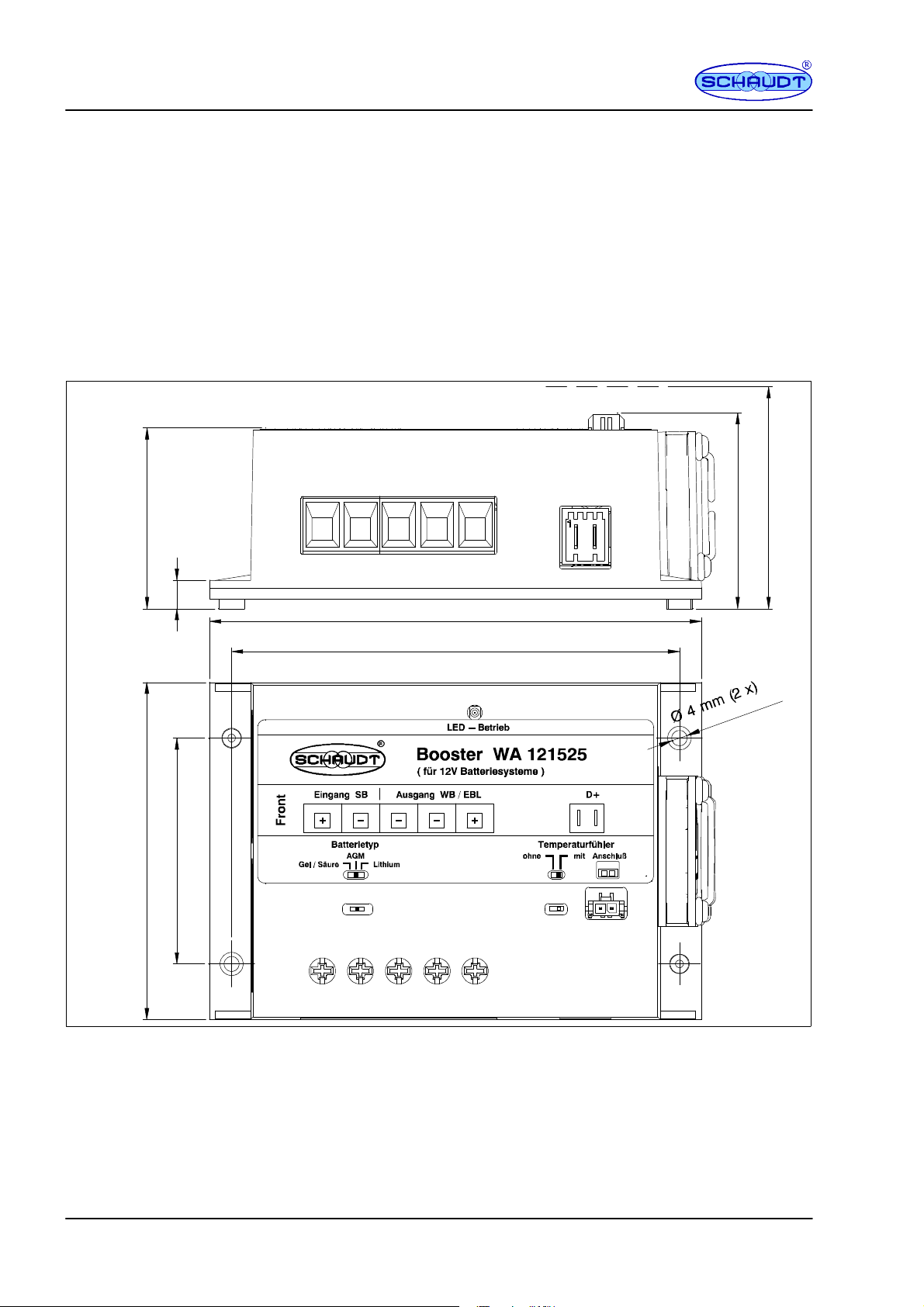
6 Installation
The device is designed for wall or floor installation.
Environment
Minimum clearance
48
7.5
" Select a dry place for installation.
" Ensure a minimum clearance to the surrounding fixtures and fittings:
F Maintain a gap of at least 5 cm on all sides (except mounted side).
F Maintain a gap of at least 80 mm upwards (projection for the connec-
tor of an optional temperature sensor).
F Whilst in operation, the ambient temperature must not exceed +45 C,
measured 1cm away from the fans opposite side of the device.
52
Projection approx. 80
131
119
60
90
Fig. 1 Dimension diagram for WA 121525Booster
Fitting
"
Screw the Booster onto a firm, flat base with two suitable screws (4mm
diameter) at the two fitting holes provided.
6
Date: 29.09.2017 8200509 BA / EN
Page 7

Operating and Installation Instructions Booster WA 121525
7 Electrical connection
The connection scenario in the vehicle must be known before the booster is
integrated into it. A distinction between the following scenarios is required:
F Vehicles with Schaudt EBL ..., for which the ground cables to both
batteries on the EBL ... are accessible individually. Refer also to Section 7.1.
Y The connection shown in Section 7.1 is the preferred scenario for best
possible distribution of currents.
F Vehicles with Schaudt EBL ..., for which the ground connection bet-
ween the two batteries is in the vehicle itself, and only a single ground
cable is connected to the EBL .... This single ground cable is usually
connected at an inaccessible place at the vehicle-side ground connection of the two batteries. Refer also to Section 7.2
F Vehicles with power supplies from other manufacturers. Here the boo-
ster is connected directly to the batteries and a D+ signal. Refer also
to Section 7.3.
Y DANGER!
The different connection scenarios have a direct bearing on the maximum
currents possible, and so the fusing required. The fusing values specified
may never be exceeded.
Every fuse must be connected in the direct vicinity of the voltage source
(so the respective battery or terminal D+ on the generator).
Y The temperature sensor also shown in the figures is available an an op-
tion. When this sensor is connected, charging of the leisure area battery
connected is controlled depending on the temperature of the leisure area
battery.
Procedure
The main procedure is essentially the same for all three connection variants:
" Fully disconnect both batteries (remove all cables from both terminals).
" Establish all cable connections as in Figure 2, 3 or 4. Ensure the cables
have the cross sections required and that the fuse holders are installed
correctly. Do not yet insert the fuses into the holders.
Y ATTENTION!
The ends of the cables connected to the screw-type terminals of the booster must NOT have wire end sleeves. Tighten the screw-type terminals to
a torque of 1.2 Nm.
" Also connect the battery sensor (if available) to the negative terminal of
the leisure area battery.
8200509 BA / EN
" Set the battery type (see Section 8.1) and switch for the temperature
sensor (Section 8.2).
" Reconnect the battery terminals of both batteries. A small electric arc
might occur because capacitors in the booster are charged.
" Finish off as described in Section 7.5.
" Insert the fuses.
Date: 29.09.2017
7
Page 8

Operating and Installation Instructions Booster WA 121525
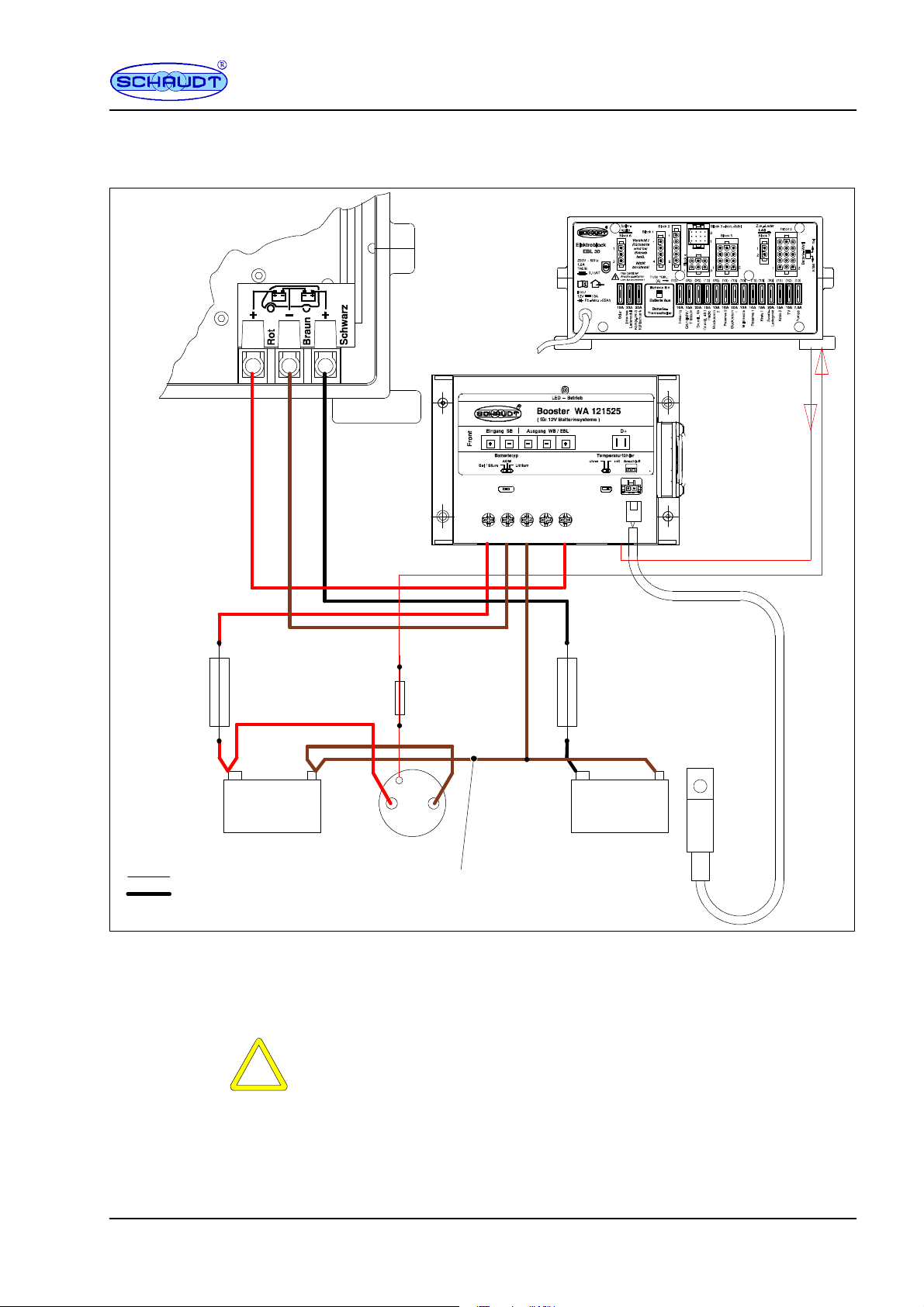
7.1 Booster connector for EBLs
with separate grounds
EBL ...
Battery connectors
(rear)
40 ... 50 A
16 mm
EBL ...
(example: EBL 30, other
EBLs also pos s ible)
D+ connector
(front)
To D+ input on
EBL
(engine running --
Lima signal)
Output D+ 12V
from EBL ... to
booster
2
50 A
2A
(60 A when all cables
are16mm
2
)
Starter
battery
Cross sections:
0.75 mm
10 ... 16 mm
+--
Battery 1
2
2
Fig. 2 Vehicles with Schaudt EBL ... -- ground on booster
For vehicles in which the cabling can be as shown in Figure 2, the ground
connection on the booster between the leisure area battery and the starter
battery is an absolute requirement. The two batteries may not be directly
connected (e.g. inside the vehicle’s cabling). If they are, the wiring must be
as in Figure 3.
Y ATTENTION!
The ground cable between the EBL and booster must have a cross section
of 16 mm
D+
G
B--B+
Generator
2
(no smaller).
Leisure area
battery
+--
Battery 2
Temperature
sensor
Battery
(optional)
8
Date: 29.09.2017 8200509 BA / EN
Page 9
EBL ...
Battery connectors
(rear)
Operating and Installation Instructions Booster WA 121525
7.2 Booster connector for EBLs and vehicle-side
grounds for batteries
EBL ...
(example: EBL 30, other
EBLs also pos s ible)
D+ connector
(front)
To D+ input on
EBL
(engine running --
Lima signal)
Output D+ 12V
from EBL ... to
booster
40 A
Starter
battery
Cross sections:
0.75 mm
10 ... 16 mm
2
16 mm
+--
Battery 1
Generator
2
2
External (vehicle-side) connection
Starter battery negative to leisure area battery
Fig. 3 Vehicles with Schaudt EBL ... -- external ground
If the ground cable of the two negative terminals has fixed routing through
the vehicle, and there is only one tap to the booster at this ground connection, the cabling looks as in Figure 3.
Y ATTENTION!
The ground cable between the EBL and booster, and between the booster
and ground connection of the batteries, must have a cross section of 16
2
(no smaller). The maximum fusing for the two batteries may be 40 A
mm
each.
D+
2A
G
B--B+
negative
2
16 mm
Leisure area
battery
40 A
+--
Battery 2
Temperature
sensor
Battery
(optional)
8200509 BA / EN
Date: 29.09.2017
9
Page 10

Operating and Installation Instructions Booster WA 121525
7.3 Booster connector in vehicles without EBL ...
*cabling already in the
vehicle
40 A ... 50 A
Starter
battery
Cross sections:
0.75 mm
10 ... 16 mm
*
+--
Battery 1
2
2
Fig. 4 Vehicles with power supplies without Schaudt EBL ...
with D+ at 12V
Vehicles without EBL (third party devices of any makes) must be retrofitted
as in Figure 4.
The connections shown in fig. 4 must also be affixed to the existing connectors on the batteries, and be fused as in the figure.
Y ATTENTION!
The maximum fusing for the two batteries may be 50 A each.
In cases where an existing booster is replaced, the old booster must be removed complete with its cabling.
2A
D+
G
B--B+
Generator
*
Leisure area
battery
40 A .... 50 A
+--
Battery 2
Temperature
sensor
Battery
(optional)
10
The connection is then analogous to the retrofit shown above.
Date: 29.09.2017 8200509 BA / EN
Page 11

Operating and Installation Instructions Booster WA 121525
7.4 Booster connector on systems with SDTBUS (Schaudt) or
third party systems (with bypass functio n )
6--10mm
40 A
(change as
required)
Starter
battery
+--
Battery 1
Cross sections:
0.75 mm
6/10 mm
2
2
Schaudt systems with
SDTBUS
Third party systems
2
Bypass relay
(in Schaudt Set
2A
part no.
9990397)
D+
D+
G
B--B+
Generator
with D+ at 12V
Fig. 5 Vehicles with SDTBUS systems or power supplies without Schaudt EBL ...
+--
Input
starter battery
EBL ... with
SDTBUS
or third party
system
Temperature sensor
for leisure area battery
(battery 2, optional)
For vehicles with SDTBUS, the booster connector shown in Fig. 5 is required for charging of the starter battery when mains voltage or solar current is
powering the electroblock. This also enables the starter battery voltage on
the system to be displayed.
Y On conventional systems, the supply cable of the fridge is used to charge
the starter battery for mains operation. The connection as in Fig. 2 or 3 is
required. No additional bypass relay is required.
On third party systems, permanently connecting the starter battery to the
system might be required. For example, the connector in Figure 5 has the
benefit (compared to the connector in Figure 4) that the voltage of the starter
battery in the third party system can also be displayed when the vehicle engine is stationary (when a display is provided there).
8200509 BA / EN
7.5 Finishing off
Y ATTENTION!
2
The10mm
potentially exert high loading on the terminals.
" The cables must be secured with suitable strain relief so that no high ten-
sile forces or pressure loads are exerted onto the connector terminals of
the booster.
- and 16 mm2- cables to the batteries are relatively heavy and
Date: 29.09.2017
11
Page 12

Operating and Installation Instructions Booster WA 121525
8 Adjustments
Y ATTENTION!
A small screwdriver must be used to move the switches. Exercise care when
moving the switches to prevent damaging them. To gain a sense for the
notch positions, the recommendation is to slide the switch left and right a
few times to the end position before making the final settings.
After making the setting, check the position again in adequate lighting.
8.1 Battery type
Y ATTENTION!
Incorrectly setting the device or using unsuitable leisure area battery types
can damage the battery or devices connected to the leisure area battery. So
therefore:
F Batteries may only be changed by qualified personnel.
F Follow the battery manufacturer’s instructions.
F Only use the booster to connect to 12V power supplies with rechar-
geable 6 cell lead-gel, lead-acid, AGM or lithium batteries. Do not use
any unsuitable battery types.
Changing the battery
Y Normally only batteries of the same type and rating should be used, i.e.
the same as those originally installed by the manufacturer.
It is possible to swap from lead-acid batteries to other battery types. Switching to lead-acid batteries is only possible in certain circumstances.
Contact the vehicle manufacturer for more information.
Y DANGER!
Incorrectly setting the battery selector switch poses a risk of explosion
(through the formation of detonating gas). So therefore:
F Move the battery selector switch to the correct position
" Electrically isolate both batteries from the booster
1
12
Fig. 6 Battery selector switch
Date: 29.09.2017 8200509 BA / EN
Page 13

Operating and Installation Instructions Booster WA 121525
" Move the battery selector switch (Fig. 6, Pos. 1) to the correct position:
Battery type used
Switch position Charge voltage Trickle charge voltage
Lead-acid batteries Left 14.4 V 13.8 V
Lead-gel batteries
Left 14.4 V 13.8 V
AGM1 batteries
AGM2 batteries Middle 14.7 V 13.7 V
Lithium batteries Right 14.4 V 14.4 V
" After changing the battery, check again the type of battery used and then
ensure that the battery selector switch is in the correct position.
8.2 Enabling/disabling th e temperature sensor
The booster is able to control charging of the leisure area battery by temperature. The optional temperature sensor is required for this.
This function must be enabled once the sensor is connected to the booster.
Changing the battery
" Connect the temperature sensor to the negative terminal of the leisure
area battery.
" Route the temperature sensor cable through the vehicle to the booster.
" Plug the connector into the booster (Figure 7, Pos. 1).
Fig. 7 Temperature sensor: Connection and setting
"
Adjust the sliding switch on the booster (Figure 7, Pos. 2).
Temperature sensor
Switch position Function
Not present Left (”without”) Fixed charge voltage / trickle charge voltage
Assuming 25 C, the charge voltage is compensated with
Present Right (”with”)
-- 2 4 m V / C until the maximum charge voltage of 15.1 V is
reached
Y If the selector switch for the temperature sensor is in Position ”with” wi-
thout a temperature sensor connected, the booster has no effect because the output voltage in this case does not exceed 7.5 V.
This mean the leisure area battery is no longer charged.
1
8200509 BA / EN
Date: 29.09.2017
13
Page 14

Operating and Installation Instructions Booster WA 121525
y
g
p
p
p
tagedoesnotriseaftersometime).houghnotemperaturesensoriscon
LEDonb
tlighti
Veh
icl
idl
t
t
Nofaul
t-startveh
icl
8.3 Faults
Flat vehicle fuses
A f lat battery or defective fuse is the cause of most faults in the 12V system.
When it is not possible to rectify a fault based on the following table, please
contact Schaudt customer service (for address, see Page 15).
Fault Possible cause Remedy
Leisure area battery not charged
when vehicle is moving (battery vol-
The voltage rises to above 14.7 V
(possible also above 15.1 V).
ooster no
ng.
The switch position for the temperature sensor is in Position ”with” alt-
nected.
Too many consumers are switched on. Switch off any consumers not requi-
When the temperature sensor is connected: Connector not plugged in properly.
When the temperature sensor is connected: Sensor cable break.
The device has an excessively high
temperature.
When the temperature sensor is connected: The sensor cable may be
short-circuited or damaged.
e engine
ging. red.
Vehicle engine running: No input voltage due to defective fuse or defective
cabling.
Vehicle engine running: No D+ signal
from the generator due to defective
fuse or fault in vehicle or in cabling.
-
e-noba
ery char-
Move the switch to the ”without” position.
-
-
red.
Plug the connector in properly.
Unplug the temperature sensor connector and move the switch (Figure 7,
Pos. 2) into Position ”without”; then
contact Customer service.
Improve the ventilation; clean dirty fan
as required.
Unplug the temperature sensor connector and move the switch (Figure 7,
Pos. 2) into Position ”without”; then
contact Customer service.
Note: Charging is no longer temperature-based.
-
Replace fuse as necessary.
Cabling: Contact customer service.
Replace fuse as necessary.
Cabling/fault in vehicle: Contact customer service.
-
e engine as requi-
-
14
Cleaning
E
9 Maintenance
The WA 121525 Booster requires no maintenance.
Clean the device with a soft, slightly moistened cloth. Never use spirit, thinners or similar substances. Do not allow liquids to enter the device. If required, clean the fan with a soft brush.
No part of this manual may be reproduced, translated or copied without express written permission.
Date: 29.09.2017 8200509 BA / EN
Page 15

Operating and Installation Instructions Booster WA 121525
Appendix
A Customer service
Customer service
Send in device
B Layout
Schaudt GmbH, Elektrotechnik & Apparatebau
Planckstraße 8
88677 Markdorf, Germany
Phone: +49 7544 9577-16
Email: kundendienst@schaudt.gmbh
Website: www.schaudt.gmbh
Y Before returning a device, we recommend taking a look at the frequently
asked questions (FAQs) on website ”www.schaudt-gmbh.de”. This may
give you some pointers towards fault rectification, or perhaps even also
incorrect operation.
Returning a faulty device:
" If possible: Fill in the pre-registration in the relevant area on the
”www.schaudt-gmbh.de” website.
" Fill in and enclose the fault report, see Appendix C.
" Send it to the addressee (free delivery).
8200509 BA / EN
12 3 4567 8 9
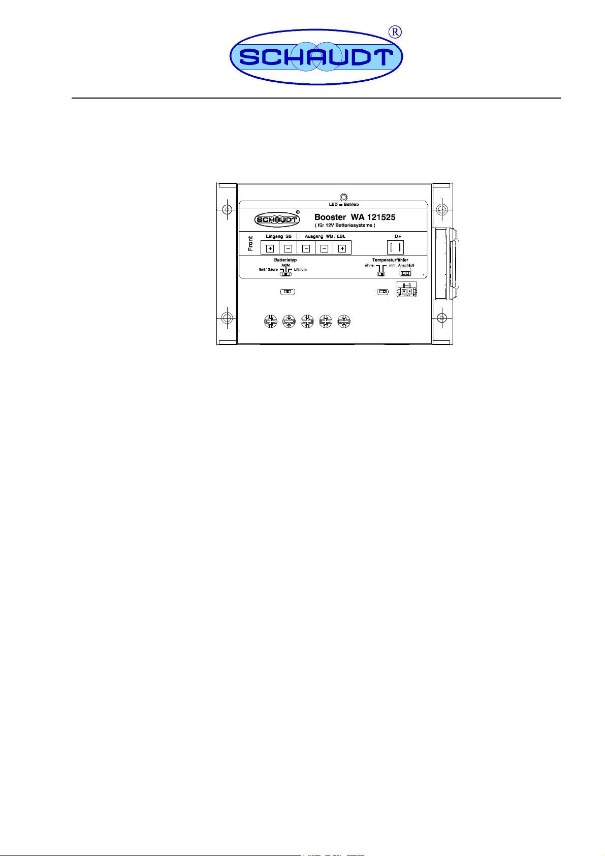
Fig. 8 Layout of the WA 121525Booster
1 Fixing hole
2 Sliding switch for battery type setting
3 Screw-type terminals for battery connectors
4 LED operation
5 Adhesive label
6 Sliding switch for temperature sensor setting
7 Temperature sensor connector plug
8 RAST 5 connector, D+
9Fan
Date: 29.09.2017
15
Page 16

Operating and Installation Instructions Booster WA 121525
C Fault report
In the event of damage, please fill in the fault report and send it with the
faulty device to the manufacturer.
Device type: _______________________
Item no.: _______________________
Vehicle: Manufacturer: _______________________
Model: _______________________
Own installation? Yes - No Upgrade? Yes - No -
Upstream overvoltage protection? Yes - No -
Following fault has occurred (please tick):
- Electrical consumers do not work -- which?
(please specify below)
- Switching on and off not possible
- Persistent fault
- Intermittent fault/loose contact
Other comments:
16
Date: 29.09.2017 8200509 BA / EN
 Loading...