


 Loading...
Satorius SC 2, MC 21 S, MC 210 P, MC 410 S, MC 5 User Manual
...98648-004-81
Sartorius Micro
Analytical, Semi-micro- and Microbalances
Installation and Operating Instructions
Contents
|
Page |
|
|
Page |
|
General Views of the Balances: |
|
|
|
Calibration/Adjustment and |
|
MC 210 S, MC 210 P and |
|
|
|
Linearization Functions |
1–30 |
MC 410 S (-0CE) |
1– |
0 |
|
Data Interface |
1–36 |
General Views of the Balances |
|
|
|
||
|
|
|
Below-Balance Weighing |
1–37 |
|
MC 5 (-0CE) and SC 2 (-0CE) |
1– |
2 |
|
||
Warranty |
1– |
4 |
|
Fastening an Antitheft |
|
Storage and Shipping Conditions 1– |
4 |
|
|
||
|
Locking Device |
1–37 |
|||
Transporting the Balance |
1– |
5 |
|
||
|
Troubleshooting Guide |
1–38 |
|||
|
|
|
|
||
Equipment Supplied Installation Instructions
Using Verified Balances Approved as Legal Measuring Instruments in the EU
Getting Started
General Instructions for “Analytical Weighing”
Weighing Electrostatically Charged Samples
and Containers Weighing Magnetic
or Magnetizable Samples General Instructions for Handling Samples and Containers
Operating the Balance
Balance Display
Turning the Display On and Off Self-Test
Opening and Closing the Draft Shield
Simple Weighing Taring
Weighing Range Structure Weighing in the IQ-Mode
Mass Unit Conversion by Toggling
Displaying the Balance Model and the Serial Number
1– |
7 |
Care and Maintenance |
1–40 |
||
|
|
||||
1– |
8 |
Servicing |
1–40 |
||
|
|
Cleaning the Balance Housing |
1–40 |
||
|
|
Cleaning the Weighing Chamber 1–40 |
|||
1– |
9 |
Safety Precautions |
1–41 |
||
|
|
|
|||
1–10 |
Balance Operating Menu |
2– |
1 |
||
|
|
Weighing in Three Ranges |
|
|
|
1–16 |
on Standard Balances |
2– |
7 |
||
Weighing in Two Ranges |
|
|
|||
|
|
|
|
||
|
|
on Verified Balances Approved |
|
|
|
1–16 |
for Use as Legal |
|
|
||
Measuring Instruments |
2–10 |
||||
|
|
||||
1–17 |
Display Modes for |
|
|
||
Standard Balances |
2–11 |
||||
|
|
||||
1–18 |
Display Modes for Verified |
|
|
||
Balances Approved for Use |
|
|
|||
1–19 |
|
|
|||
As Legal Measuring Instruments |
2–13 |
||||
1–19 |
Calibration Functions on |
|
|
||
1–20 |
Standard Balances |
2–14 |
|||
1–20 |
Calibration Functions on Verified |
|
|
||
1–21 |
Balances Approved for Use |
|
|
||
as Legal Measuring Instruments |
2–16 |
||||
1–26 |
Utilities for Printouts |
|
|
||
1–26 |
or Data Transfer |
2–18 |
|||
1–27 |
Additional Functions |
2–21 |
|||
1–28 |
ISO/GLP-compliant Printout |
|
|
||
1–29 |
|
|
|||
or Record |
2–25 |
||||
|
|
||||
1–29 |
Setting the ID No./Date/Time |
2–30 |
|||
0–0

|
Page |
|
|
Page |
||||
Application Programs |
3– |
1 |
|
Interface Description |
4– |
1 |
||
Functions Common to |
|
|
|
Pin Assignment Chart |
4–19 |
|||
|
|
|
Cabling Diagrams |
4–20 |
||||
All Programs |
3– |
3 |
|
|||||
|
|
|
|
|
||||
c Key |
3– |
3 |
|
|
|
|
|
|
|
Specifications |
|
|
|||||
Information and Printouts |
|
|
|
5– |
1 |
|||
or Data Transfer |
3– |
4 |
English Translation of the |
|
|
|||
Data ID Code K* or NUM |
3– |
4 |
EC Type-Approval Certificate |
|
|
|||
“EUREKA” Air Buoyancy |
|
|
|
for MC 5-0CE |
5– |
6 |
||
|
|
|
|
|
|
|
||
Correction Program |
3– |
5 |
|
Accessories (Options) |
5– |
7 |
||
Differential Weighing and |
|
|
|
|
|
|
|
|
|
|
|
|
|
|
|
||
Backweighing |
3–14 |
Declarations of Conformity |
6– |
1 |
||||
Weighing Sequence |
3–15 |
|
|
|
|
|||
Selecting the Memories |
3–17 |
|
|
|
|
|||
Index |
7– |
1 |
||||||
Key Functions |
3–18 |
|||||||
|
|
|
|
|||||
Clearing the Memory |
3–31 |
|
|
|
|
|||
|
|
|
|
|||||
Density |
3–34 |
Supplement: |
|
|
|
|||
Diameter Determination |
3–42 |
Brief Operating Instructions |
|
|
|
|||
|
|
|
|
|||||
Tare Memory |
3–44 |
|
|
|
|
|||
Weighing in Percent |
3–47 |
|
|
|
|
|||
Over/Under Checkweighing |
3–51 |
|
|
|
|
|||
Counting |
3–55 |
|
|
|
|
|||
Error Codes |
3–59 |
|
|
|
|
|||
0–1

General View of the Balances:
MC 210 S, MC 210 P and MC 410 S (-0CE)
1–0

1Large draft shield cover
2Small draft shield cover
3Exterior draft shield element, semicylindrical
(can be moved by hand)
4Interior draft shield door, semicylindrical (can be moved by motor control or by hand)
5Interior weighing chamber draft shield only on MC 210 S, MC 210 P (-0CE)
6Protective ring
7Weighing pan
8Protective disk
9Leveling foot
10Level indicator
11Display unit
12AC jack/power socket
13Menu access switch
14Data interface port
15Terminal for connecting an equipotential bonding conductor
16Lug for attaching an antitheft locking device
17Metrological ID label for verified balances approved for use as legal measuring instruments
18Manufacturer’s label
19Application display
20Numeric keys
21f function key
22F function key
23r and l draft shield function keys
24p Print key (data transfer)
25Function display for the f and F keys
26t Tare key
27Application program display
28Weight display
29w toggle key
30Info key
31ON/OFF key e
32c key
33Bar graph (range indicator)
34Verification ID label with metrological data for verified balances approved for use as legal measuring instruments
1–1
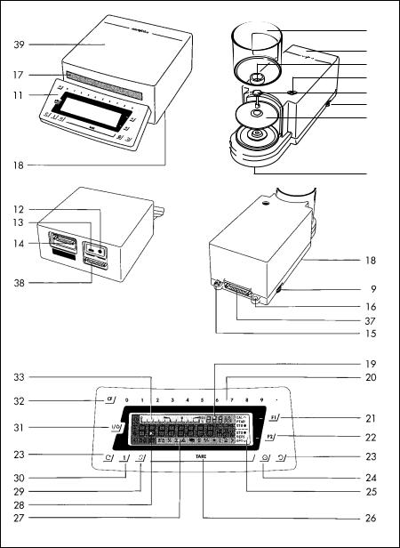
General View of the Balances:
MC 5 (-0CE) and SC 2 (-0CE)
34
35
36
10
7
9
8
37
1–2

7Weighing pan
8Protective disk
9Leveling foot
10Level indicator
11Display and control unit
12AC jack
13Menu access switch
14Data interface port
15Terminal for connecting an equipotential bonding conductor
16Lug for attaching an antitheft locking device
17Metrological ID label for verified balances approved for use as legal measuring instruments
18Manufacturer’s label (on bottom of balance)
19Application display
20Numeric keys
21f function key
22F function key
23r and l draft shield function keys (for opening and closing)
24p Print key (data transfer)
25Function display for the f and F keys
26t Tare key
27Application program display
28Weight display
29w toggle key
30Info key
31ON/OFF key e
32c key
33Bar graph (range indicator)
34Draft shield
35Weighing cell
36Inner draft shield
37Below-balance weighing port
38Male connector on weighing cell
39Male connector on computing device
40Electronic computing device
1–3
Please read these installation and operating instructions carefully before you begin to operate your new balance.
Warranty
Do not miss out on the benefits of our full warranty. Please contact your local Sartorius office or
dealer for further information. If available, complete the warranty registration card, indicating the date of installation, and return the card to your Sartorius office or dealer.
Storage and Shipping Conditions
Allowable storage temperature: +5°C ... +40°C +41°F to +104°F
The complete packaging has been designed to ensure that the balance will not be damaged even if it is dropped from a height of 80 cm (about 31 inches).
After unpacking the balance, please check
it immediately for any visible damage as a result of rough handling during shipment.
If this is the case, proceed as directed in the section entitled “Safety Inspection.”
Save all parts of the packaging and the box for your balance to avoid damage during transportation. Ship your balance only in the complete original standard packaging supplied.
The packaging consists of the following:
–2 boxes
–3 polystyrene inserts
–2 polypropylene pads
The inner packaging is not suitable for shipping because it provides the balance little protection from blows. Before packing your balance for shipment, unplug all connected cables to prevent damage.
Do not expose the balance unnecessarily to extreme temperatures, moisture, shocks, blows or vibrations.
1–4
Transporting the Balance
To transport the balance, lift it by the housing base using both hands. Never lift your balance by grasping the display unit or the draft shield!
Transport Arrestment
Before unplugging the balance from the power supply or unplugging the connecting cable, turn off the balance using the e key (31).
For MC5 (-0CE) and SC 2 (-0CE):
After approximately 10 seconds, the balance will be arrested, or locked, for transportation.
While the balance is raising the weights after you have turned it off, the symbol “Mot” from a calibration or linearization procedure is displayed.
Warmup Time
Condition your balance for 12 hours to the temperature of a new location. After initially connecting the balance to AC power (or after a relatively long power outage), allow it to warm up for at least 2 hours.
Each time you move your balance to another location, you must condition it for at least 12 hours to the
new location.
After initially connecting the balance to AC power (or after a relatively long power outage), allow the balance to warm up for at least 2 hours.
1–5

Note to Users of Verified Balances Approved for Use as Legal Measuring Instruments:
Preparing a Verified Balance for Use as a Legal Measuring Instrument:
After initially connecting the balance to AC power (or after a relatively long power outage), allow
it to warm up for at least 24 hours.
Linearization after Transport
After transport, the linearity and calibration of your balance may be out of the permissible tolerances (see the “Specifications”). Always carry out internal linearization of the balance after transport.
Repeating this procedure – several times, if necessary – enhances the linearization. This procedure is described on page 1–35.
1–6
Equipment Supplied
The equipment supplied includes the components listed below:
MC 210 S, MC 210 P and MC 410 S (-0CE)
–Weighing cell
–AC adapter
–Weighing pan
–Protective disk
–Protective ring
–Interior weighing chamber draft shield
–2 draft shield covers
–Dust cover for the draft shield and the balance housing
–Dust cover for the display unit
MC 5 (-0CE) and SC 2 (-0CE)
–Weighing cell
–Draft shield
–Electronic computing device
–Connecting cable
–Power supply
–Kit of standard accessories
–Inner draft shield (models SC 2 and SC 2-0CE only)
The kit of standard accessories contains the following:
–Weighing pan
–Protective disk
–Brush
–Forceps
–Lint-free cloth
MC 21S
–Weighing cell
–Electronic computing device
–Connecting cable
–Power supply
–Protective disk
–Protective ring
–Weighing pan
1–7
Installation Instructions
Ambient Conditions
Before you set up your balance, choose a suitable place which meets the following requirements:
–level, low-vibration weighing table or a wall console;
–no direct exposure to sunlight, heaters, or similar sources of heat. This can considerably increase the temperature inside the draft shield
(greenhouse effect), resulting in incorrect readouts due to convection currents, turbulence and buoyancy effects;
–no drafts from open windows or doors;
–avoid brief fluctuations in room temperature.
The balance is not allowed to be used in hazardous areas/locations where there is danger of explosion.
Do not expose the balance to extreme moisture over long periods. Moisture in the air can condense on the surfaces of a cold balance whenever it
is brought to a substantially warmer place.
If you transfer the balance to a warmer area, make sure to condition it for about 2 hours at room temperature, leaving it unplugged.
1–8

Using Verified Balances Approved as Legal Measuring Instruments in Europe (only applies to MC5-0CE)
Using Verified Balances as Legal Measuring Instruments
You must calibrate the balance at the place
of installation before using it as a legal measuring instrument (see the section entitled “Calibration/ Adjustment” starting on page 1–31).
This balance is not allowed to be used for weighing goods intended for direct sale to the public. The type-approval certificate for verification applies only to non-automatic weighing instruments; for automatic operation with or without auxiliary measuring devices, you must comply with the regulations of your country applicable to the place of installation of your balance. A suitable thermometer and barometer are recommended for monitoring ambient conditions.
For balances of accuracy class k, a thermometer and barometer are recommended for monitoring ambient conditions. The temperature range indicated on the verification ID label must not be exceeded during operation.
The balance must warm up for at least 24 hours after initial connection to AC power or after
a relatively long power outage.
The legal background for using Sartorius balances in legal metrology is the EC Council Directive No. 90/384/EEC for non-automatic weighing instruments, which has been in effect since January 1, 1993, within the Internal European Market, as well as the accreditation of the Quality Management System of Sartorius AG
by Lower Saxony’s Regional Administrative Department of Legal Metrology (Niedersächsische Landesverwaltungsamt – Eichwesen) from February 15, 1993.
1–9

Getting Started
MC 210 S, MC 210 P and MC 410 S (-0CE):
Important Note Concerning Verified Balances Approved for Use as Legal Measuring Instruments:
Provided that an official lead seal is required for the verified balance, a control seal is affixed to the balance. Unauthorized attempts to remove this seal will irreversibly damage it. If you break the seal, the validity of the verification will become void, and you must have your balance subsequently verified.
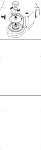
Place the components listed below inside the weighing chamber one at a time in the order given:
–Shield disk (8)
–Weighing pan (7)
–Protective ring (6)
–Interior weighing chamber draft shield (5) (only on MC 210 S, MC 210 P (-0CE))
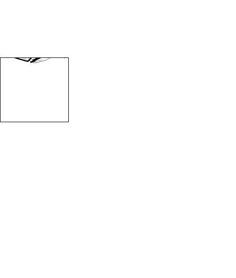
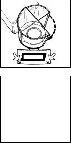
–Place the small draft shield cover (2) on top of the semicylindrical interior draft shield door (4).
Then place the large draft shield cover (1) on top
of the semicylindrical exterior draft shield element (3). Secure the draft shield cover in place using the fastener (see arrow).
1–10
Adjusting the Exterior Draft Shield Element
Turn the exterior draft shield element (3) by the riffled part on the bottom to the position you desire. Depending on your application, you can define
the menu code so that the interior draft shield door (4) is operated by motor or by hand (see section
starting on page 1–21).
Adjusting the Swivel-Mounted Display Unit
Move the swivel-mounted display unit (11) around the base of the draft shield to adjust it to the position you desire (+/– 85°).
MC 21S:
Installing the Components
§Place the following components on the balance in the order given below:
–Shield plate
–Weighing pan
Note: To position the weighing pan, rotate it back and forth while pressing down gently.
–Protective ring
–Glass plate
1–11
MC 5 (-0CE) and SC 2 (-0CE):
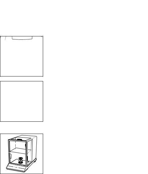
Assembling the Components
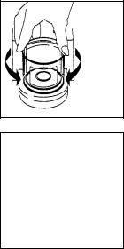
§Place the components listed below on the weighing cell (35) one at a time in the order given:
–Protective disk (8)
–Weighing pan (7)
Important Note: After placing the weighing pan on the weighing cell, press down on it gently while turning it slightly to the left and right.
–Inner draft shield (36) (models SC 2 and SC 2-0CE only)
Installing and Adjusting the Draft Shield
–Place the small draft shield (34) on the weighing cell and adjust it so that the gap fits over the projection on the weighing cell (see arrows).
Connecting the Weighing Cell to the Computing Device
Connect these two units so that the two points
where the connecting cable is attached to the female connectors face each other (see arrows).
Tighten the screws on the female connectors by hand.
1–12
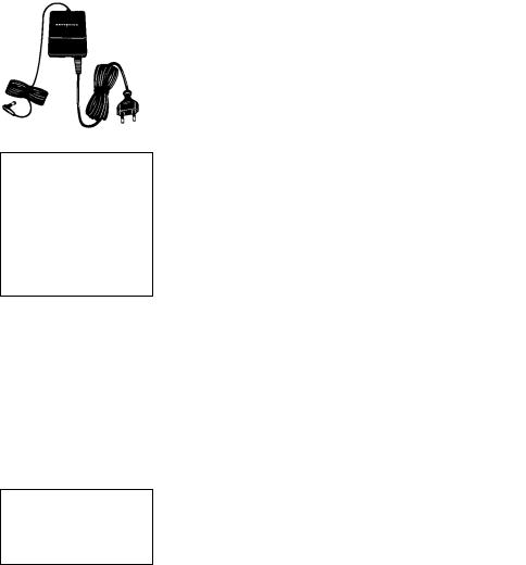
Connecting the Balance to AC Power
The balance is energized by a power supply/AC adapter. Make sure that the voltage rating printed on this unit is identical to your local line voltage.
If the voltage specified on the label or the plug design of the power supply/AC adapter does not match
the rating or standard you use, please contact your Sartorius office or dealer.
Important Note:
Use only original Sartorius power supplies/AC adapters. Use of power supplies/AC adapters from other manufacturers, even if these units have
an approval identification marking from a national testing laboratory, requires the consent
of an authorized Sartorius service technician.
Detailed information on additional options
for powering the balance is available in our service information bulletin, no. 15/88 (for example, using local extra-low voltage).
Plug the cord of the AC adapter/power supply into the DC jack on the rear panel of the balance/computing device. Then insert the plug of the power supply or the AC adapter into a wall outlet.
1–13

|
|
|
|
|
|
|
|
Voltage Selection |
|
|
|
|
|
|
|
|
|
|
|
|
|
|
|
|
|
You can select the voltage if you use our portable |
|
|
|
|
|
|
|
|
|
230 V~ |
|
|
|
|
|
|
V~ |
power supply (6971172) that has a European-type |
|
|
|
|
|||||
|
|
|
|
|
|
|
|
plug (rounded prongs). |
|
|
|
|
|
|
|
|
Safety Precautions |
|
|
|
|
|
|
|
|
The power supply/AC adapter rated to Class 2 can |
|
|
|
|
|
|
|
|
be plugged into a wall outlet without taking any |
|
|
|
|
|
|
|
|
additional safety precautions. The pole of the output |
|
|
|
|
|
|
|
|
voltage is connected to the balance housing, which |
|
|
|
|
|
|
|
|
can be grounded for operation. |
|
|
|
|
|
|
|
|
The data interface (see also “Interfacing Devices” |
|
|
|
|
|
|
|
|
on page 1–36) is also electrically connected to the |
|
|
|
|
|
|
|
|
balance housing (ground). |
|
|
|
|
|
|
|
|
Information on Radio Frequency Interference |
|
|
|
|
|
|
|
|
Warning! |
|
|
|
|
|
|
|
|
This equipment generates, uses and can radiate radio |
|
|
|
|
|
|
|
|
frequency energy and, if not installed and used in |
|
|
|
|
|
|
|
|
accordance with the instruction manual, may cause |
|
|
|
|
|
|
|
|
interference to radio communications. It has been |
|
|
|
|
|
|
|
|
tested and found to comply with the limits for a Class A |
|
|
|
|
|
|
|
|
computing device pursuant to Subpart J of Part 15 of |
|
|
|
|
|
|
|
|
FCC rules, which are designed to provide reasonable |
|
|
|
|
|
|
|
|
protection against such interference, when operated |
|
|
|
|
|
|
|
|
in a commercial environment. Operation of this |
|
|
|
|
|
|
|
|
equipment in a residential area is likely to cause |
|
|
|
|
|
|
|
|
interference, in which case the user at his own |
|
|
|
|
|
|
|
|
expense will be required to take whatever measures |
|
|
|
|
|
|
|
|
may be required to correct the interference. |
|
|
|
|
|
|
|
|
Connecting Electronic Devices (Peripherals) |
|
|
|
|
|
|
|
|
Make sure to unplug the balance from the power |
|
|
|
|
|
|
|
|
supply/AC adapter before you connect or disconnect |
|
|
|
|
|
|
|
|
a peripheral device (printer or PC) to or from the |
|
|
|
|
|
|
|
|
interface port. |
1–14

Leveling the Weighing Cell Using the Level Indicator
At the point of use, level the weighing cell using the leveling feet (9) so that the air bubble is centered within the circle of the level indicator (10).
To level the weighing cell using the level indicator as a guide:
Extend the leveling feet (turn clockwise) to lift the weighing cell.
Retract the feet (turn counterclockwise) to lower the weighing cell.
1–15
General Instructions for “Analytical Weighing”
Weighing Electrostatically Charged Samples and Containers
Major measuring errors can occur when electrostatically charged samples and containers are weighed. This problem particularly involves samples that have an extremely poor electrical conductivity (glass, plastic, filters) since they can discharge electrostatic – i.e., friction-induced – charges only over a relatively long period of time. The result
is an interaction of forces among the charges adhering to the sample and the stationary components of the balance (base plate of the weighing chamber, draft shield construction, balance housing). This
is noticeable when the weight readout drifts. At a high humidity, this effect is not so pronounced or does not even occur at all due to the thin layer of water that condenses on the sample and, through conductive discharge, counteracts interfering static electricity.
In addition to taking purely mechanical counteractive measures (protecting the sample using a special antistatic weighing pan – see the “Accessories”), you can neutralize the surface charges by “bombarding” them with ions of the opposite polarity. This
is an extremely effective method of eliminating static electricity on surfaces (antistatic ionizing blower, order no. YIB01).
The balance’s environment, including the operator, can considerably interfere with weighing on account of static electricity. The balances of the MC Series have been designed to counteract this phenomenon: the glass surfaces of the draft shield have a special metallic coating.
The rear panel of the balance/weighing cell
has a terminal (15) for connecting an equipotential grounding conductor. It is used for additionally grounding a peripheral device (for example,
a vibrating spatula). This terminal is designed for single grounding wires up to .25” standard gauge or 6 mm2 and for .18” standard gauge or 4 mm2 stranded wires.
1–16
Weighing Magnetic or Magnetizable Samples
It is technically impossible to avoid the use of magnetizable materials in the manufacture
of balances. Ultimately, the operating principle of high-resolution balances is based
on electromagnetic force compensation of the load placed on the weighing pan.
When magnetic or magnetizable samples
or containers (e.g., beaker with a stirrer) are weighed, interactions among the above-mentioned components of the balance may occur, distorting weight readouts.
Unlike deviations caused by electrostatic charges, magnetic interference is usually constant over
time. However, it is sensitive to and depends on the position of the sample or container on the weighing pan and is also characterized by poor reproducibility.
To reduce the effect described above, we recommend increasing the distance between the sample and
the weighing pan by using a non-magnetizable material (the reduction in force is proportional to the quadrate of the distance). In special cases, soft-magnetic plates should be used to shield against interfering magnetic effects.
In the presence of extremely strong magnetic fields – for instance, when measuring the susceptibility
of a sample in an electromagnet – you should use the below-balance weighing port which comes standard on your balance.
1–17
General Instructions for Handling Samples and Containers
As a general rule, the sample to be weighed should be conditioned to the temperature of the balance. This is the only way to avoid air buoyancy errors and deviations caused by convection currents at the surface of the sample. Since these effects increase proportionally to the volume and surface of the sample, make sure that the size of the tare vessel selected is in the appropriate proportion to the size of the sample to be weighed.
Never use your bare hands to touch samples to be weighed. In addition to the effect on the
temperature, the extremely hygroscopic behavior of fingerprints left on the sample will cause
considerable interference during weight measurement. Use forceps or other suitable utensils to place your sample carefully on the pan.
Working with your balance requires a steady hand and a smooth, uninterrupted technique.
Perform a few trial weighing operations before you begin with the actual weighing of your sample because the temperature in the weighing chamber may differ from that of the balance’s surrounding environment, if the weighing chamber has not been opened for a relatively long period.
When you open the weighing chamber, a change in temperature will inevitably occur, due to the laws of physics, and may show up as a change
in the weight readout. In this case, we recommend that before you begin the actual weighing series you open and close the weighing chamber at the same rate as you will be doing during weighing.
After the weighing chamber has been closed, the weight readout will usually stabilize after about
10 seconds. The accuracy of the weight readout will increase as you perform successive weighing procedures with greater consistency.
1–18

Operating the Balance
Balance Display
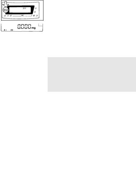
The display shows the following special codes for your information:
OFF
The balance was disconnected from AC power
(power failure or outage; the balance was reconnected to AC power).
O (standby)
The display has been turned off by the e key (31). The balance is now in the ready-to-operate mode.
b (busy)
Once you have turned on the balance, the b symbol will be displayed until you press a key.
During operation, this symbol indicates that the balance processor is still busy processing a function and will not accept commands to perform any other functions at this time.
CAL I
The balance has internal calibration weights and can be calibrated using the f key.
R1 W or R2 W
The number in the R code identifies the particular weighing range you have selected.
W
Symbol for the application selected (in this case, the weighing mode and toggling among the weighing ranges).
Important Note:
If the W symbol flashes, this means that the balance wants to self-calibrate (see pp. 1–30).
1–19
Turning the Display On and Off (Standby Mode)
Press the e key (31) to turn the display on or off.
Self-Test
After the balance has been turned on, an automatic self-test of the balance’s electronic circuitry
is performed, and the draft shield closes automatically. When a zero readout is displayed, the balance
is ready for operation.
Important Note Concerning Verified Balances Approved for Use as Legal Measuring Instruments in the E.U.*
For verified balances that have a verification scale interval “e” which is greater than the scale interval “d,” and a scale interval “d” ≥ 0.1 mg, the last digit on the display is bordered.
Automatic Warmup of the Balance Electronics in MC 210 S, MC 210 P and MC 410 S (-0CE), MC 21S
Once you have connected the balance to AC power and turned on the power, the balance’s electronics automatically begin to warmup. The timer for warmup is set to 4 minutes. The remaining warmup time in minutes and seconds is displayed in
a countdown mode.
When the remaining time displayed is less than one minute, you can interrupt this warmup procedure by pressing the e key to turn the balance off and back on again. Following the self-test and display of a zero readout,
the balance is ready to operate again.
After 4 minutes have elapsed, the balance displays a zero readout and is then ready to operate.
*= including the Signatories of the Agreement on the European Economic Area
1–20

Opening and Closing the Draft Shield
MC 210 S, MC 210 P or MC 410 S (-0CE):
To load small objects, open the draft shield only
as far as is absolutely necessary for your application. This reduces the amount of draft so your balance
will stabilize faster than it normally does when the draft shield is wide open.
You have several options for operating the interior draft shield door (4):
–Semi-automatically using the l or r key (23) (max. aperature angle: 170°)
–Using an external foot or hand switch (see part 5, “Accessories”)
–By a command from an on-line computer (see part 4, “Interface Description”)
–Fully automatically, e.g., for the functions tare, calibration, print, etc. (see part 2, “Balance Operating Menu”)
–With a special display mode while the draft shield is open (see part 2, “Balance Operating Menu”)
–Manually
Semi-automatic Mode with an Aperture
Angle of 10° to 140°
By a “self-teaching” function, the draft shield door can “learn” to open automatically to a user-defined aperture angle between 10° and 140°:
To define this angle, manually move the interior draft shield door (4) to the desired position.
1–21
Press either l or r to close the draft shield automatically by motor. While closing, the interior draft shield door moves slowly. The previously adjusted aperture angle is stored.
If you press either l or r once again, the draft shield door will open at a faster speed to the position you have selected. Press l or r for approx.
2 seconds to open the draft shield door automatically as far as it will go (170°).
You can always change the aperture angle by manually adjusting the position of the draft shield door.
Important Note
The aperture angle remains stored even after you have turned off the display by pressing e.
A stored aperture setting will not be erased until you unplug the balance from AC power.
Manual Mode
Of course, you can also open and close the draft shield door by hand.
1–22

MC 5, SC 2 (-0CE):
You can operate the motorized draft shield (34) in one of the following ways:
–Semiautomatically using the l or r key (23) (aperature angle approx. 100°)
–Using an external foot or hand switch (see part 5, “Accessories”)
–By a command from an on-line computer (see part 4, “Interface Description”)
–Fully automatically, e.g., for the functions tare, calibration, print, etc. (see part 2, “Balance Operating Menu”)
–With a special display mode while the draft shield is open (see part 2, “Balance Operating Menu”)
–Manually
1–23
Semi-automatic Mode with the Aperture Angle of Your Choice
To define the aperture angle and the direction in which the draft shield opens, move the draft shield to the desired position manually (aperture angle 45° to 315°).
Press either the l or r key (23) to have the
draft shield closed by motor. The previously adjusted aperture angle and the direction are stored in
the process.
You can always change the aperture angle by manually adjusting the position of the draft shield.
You can clear the aperture angle by either
– entering an aperture < 45° using the numeric keys (e.g., “0”) and confirming this entry by pressing the l or r key
or
– by closing the draft shield manually
Important Note:
The aperture angle and the direction in which the draft shield opens remain stored even after you have turned off the display using the e key.
This information will not be erased until you unplug the balance from AC power.
1–24

Numeric Entry of an Aperture Angle
The numeric entry of an aperture angle corresponds to a fixed position. The aperture is measured counterclockwise starting from the closed draft shield position:
–Enter an aperture angle between 45° and 315° using the numeric keys (20); e.g., 210
–Confirm this entry by pressing either the
l or r key (23), depending on the direction you wish the draft shield to open
–The aperture angle and the direction are now stored for further operation
You can clear the aperture angle by either
–entering an aperture < 45° using the numeric keys (e.g., “0”) and storing this entry by pressing
the l or r key or
– by closing the draft shield manually
Important Note:
The aperture angle and the direction in which the draft shield opens remain stored even after you have turned off the display using the e key. This information will not be erased until you unplug the balance from AC power.
Opening and Closing the Draft Shield Manually
Of course, you can also open and close the draft shield by hand.
!Important Note:
An open draft shield will always close automatically if you have not operated the balance for 1 minute. Exception:
–It will not close automatically if you have set menu code 8 8 1 “Automatic draft shield function off” (see part 2, “Balance Operating Menu”)
1–25

Simple Weighing
Place your sample on the weighing pan (7), and close the draft shield door. Read off the weight indicated on the display (28) only after the weight unit (“g”, or a different unit selected – see part 2, “Balance Operating Menu”) appears as the stability symbol.
Important Note Concerning Verified Balances of Accuracy Class k
To avoid measuring errors, the respective air density must be allowed for. The following formula is used to calculate the mass of the sample:
m = nw 1– ρL/8000 kg m–3 1– ρL/ρ
m = mass of the sample nw = weight readout
ρL = air density during weighing ρ = density of the sample
Taring
If you wish to use a container or if the weight display does not indicate 0.000 mg (depending on the display mode or weight unit selected), zero the display before you weigh.
To do so, press tkey (26).
During taring, you can have the fully automatic draft shield function either on or off.
For more information on turning this fully automatic draft shield function on or off by menu code, refer to part 2, “Balance Operating Menu.”
Important Note for Verified Balances Approved for Use as Legal Measuring Instruments:
The small circle in the weight display (on the left) shows that the balance is exactly tared to “0” (± 0.25 of a scale interval).
1–26
Loading...