

Page 1
Operating Instructions
Sartorius ME and SE Series
ME and SE Models from 2005 and Later
Electronic Analytical and Semi-microbalances
98648-008-84
Page 2

ME and SE models are high-resolution
balances of special accuracy for
extremely precise measurement of mass.
These series cover a range from
0.001 mg to 610 g.
A broad range of special performance
features makes the ME and SE balances
ideal for use as measuring and test
equipment in ISO or GLP quality management systems.
These features include:
– The fully automatic self-calibrating
and adjustment function, isoCAL
(time- and temperature-dependent)
– reproTEST for quick determination of
the standard deviation to check the
repeatability of results
– ISO/GLP-compliant recording capability
for printouts
– Password-protected menu lock
– Display of maintenance |
service intervals when due
ME and SE balances meet the highest
requirements placed on the accuracy
and reliability of weighing results
through the following features:
– Efficient filtering-out of vibration
– Fully automatic draft shield with three
motorized, self-teaching draft shield
elements and soft-touch technology
– Stable and repeatable results
– Excellent readability under any
lighting conditions
– Rugged design and durable weighing
system
ME215/235/254/414/614:
– Integrated static electricity eliminator
feature to neutralize interfering electrostatic charges (ionizer)
ME and SE balances save work and
speed up both simple and complex
routine applications through:
– Ultrafast response times
Built-in application programs;
application level 1:
– Second weight unit
– Counting
– Weighing in percent
– Animal weighing
– Recalculation
– Calculation
– Density determination
– Differential weighing
– Air buoyancy correction
– Air density determination
for ME5, SE2
Application level 2:
– Checkweighing
– Time-controlled functions
Application level 3:
– Totalizing
– Formulation
– Statistics
with the following additional functions:
– Second tare memory
– Identification codes
– Product data memory
– SQmin function
– Manual data storage in
application level 3
– DKD uncertainty of measurement
– Automatic initialization when you
switch on the balance
– Easy input of IDs for
samples or other weighed objects
– If requested: control using an
external computer
Symbols
The following symbols are used in
these instructions:
● indicates steps you must perform
$ indicates steps you must perform
only under certain conditions
> describes what happens after you
have performed a certain step
– indicates an item in a list
! indicates a hazard
Conventions Used in These
Operating Instructions:
– The pictures in these Operating
Instructions are based on the
ME215S model. On other models,
some display readouts and printouts
may differ slightly from the ones
shown. This will be explained in
cases where this is important for
operation of the balance.
Hotline:
For advice on the use of applications, just call or fax your local
Sartorius office. For the address,
please visit our Internet website at:
www.sartorius.com
2
Intended Use
Page 3

2 Intended Use
3 Contents
4 Warning and Safety Instructions
5 General Views of the Balances
7 Operating Design
11 Getting Started
11 Storage and Shipping Conditions
11 Unpacking the Balance
11 Carrying the Balance
11 Equipment Supplied
12 Installation Instructions
12 Remote Operation of the
Display and Control Unit
14 Connecting the Balance to AC Power
15 Warmup Time
16 Leveling the Balance
17 Configuring the Balance
17 Selecting the Language
18 Navigating in the Setup Menu
19 Entering the Time and Date
20 Setting the Balance Functions
23 Setting the Device Parameters
23 Entering a Password
27 Setting the Application Parameters
36 Selecting the Printout Function
38 Printout Configuration
40 Device Information
40 Factory Settings
41 Operating the Balance
41 Basic Weighing Function
41 General Instructions for
“Analytical Weighing”
42 Below-Balance Weighing
45 Device Parameters
45 Opening and Closing the Draft Shield
47 Static Electricity Eliminator (Ionizer)
49 Calibration, Adjustment, Linearization
59 Repeatability Test
60 Application Programs
61 Toggle between Two Weight Units
63 Counting
66 Weighing in Percent
69 Calculation
72 Density Determination
77 Differential Weighing
89 Air Buoyancy Correction
96 Diameter Determination
99 Time-Controlled Functions
102 Statistics
3
Contents
107 Extra Functions
107 Second Tare Memory
109 Individual Identification Codes
113 Saving Values Manually in M+
114 Changing the Resolution
116 Product Data Memory
118 SQmin Function
120 DKD Uncertainty of Measurement
122 Combining Applications
123 Practical Combination of Several
Applications (Example)
125 Data Output Functions
127 Interfaces
130 Printouts
134 Serial Communications Port
139 Pin Assignment Charts
140 Cabling Diagram
141 Error Codes and Messages
144 Care and Maintenance
145 Recycling
146 Overview
146 Specifications
152 Accessories (Options)
153 Dimensions (Scale Drawing)
155 Declarations of Conformity
158 EC Type-Approval Certificate
160 Plates and Markings
162 Index
Appendix
Entering the General Password
Brief Instructions
Page 4

This balance complies with the
European Council Directives as well
as international regulations and
standards for electrical equipment,
electromagnetic compatibility, and
the stipulated safety requirements.
Improper use or handling, however,
can result in damage and/or injury.
Read these operating instructions
thoroughly before using your
balance to prevent damage to the
equipment. Keep these instructions
in a safe place.
Follow the instructions below
to ensure safe and trouble-free
operation of your balance:
!
Do not operate in a hazardous
area/location
!
Make sure that the voltage rating
printed on the AC adapter is identical
to your local line voltage
!
If you use electrical equipment in
installations and under ambient
conditions requiring higher safety
standards, you must comply with the
provisions as specified in the applicable regulations for installation in
your country.
– The only way to switch the power off
completely is to disconnect
the AC adapter
– The balance housing is protected
against the penetration of solid objects
with a diameter of more than 2.5 mm
(such as accumulated dust) and
dripping water falling vertically (IP32) –
the housing is not completely dustand leak-tight, however
– Protect the AC adapter from contact
with liquid
– Note on Installation:
The operator shall be responsible for
any modifications to Sartorius equipment and for any connections of cables
or equipment not supplied by Sartorius
and must check and, if necessary,
correct these modifications and connections. On request, Sartorius will provide
information on the minimum operating
specifications (in accordance with the
Standards listed above for defined
immunity to interference).
– Connect only Sartorius accessories and
options, as these are optimally designed
for use with your balance
When cleaning your balance, make
sure that no liquid enters the balance
housing; use only a slightly moistened
cloth to clean the balance.
Do not open the balance housing.
If the seal is broken, this will result in
forfeiture of all claims under the
manufacturer‘s warranty.
In case you have any trouble with your
balance:
$ contact your local Sartorius office,
dealer or service center
4
Warning and Safety Instructions
Page 5
5
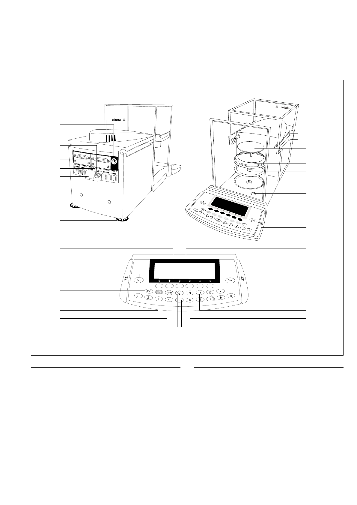
Models ME215/235/254/414/614
General Views of the Balance
Pos. Designation Spare Part Order No.
17 On/off key
18 Toggle key for alphabetic input
19 Function keys
20 Leveling foot 69MA0091
21 Lug for attaching antitheft locking device
22 Menu access switch
23 Serial printer port (PRINTER)
24 Serial communications port
(PERIPHERALS)
25 Terminal for connecting an
equipotential bonding conductor
26 DC jack
Not shown:
Set of dust covers 6960ME01
Set of small parts (operating panel) 69ME0007
Set of caps 69ME0008
Pos. Designation Spare Part Order No.
1 Draft shield door grips
2 Weighing pan 69 ME0001
3 Shield disk (ME235S/P only)
4 Shield plate 69 ME0002
5 Level indicator
6 Operating panel
7 Display
8 Tare key
9 Key for opening/closing 69ME0007
draft shield (set of small parts)
10 Decimal point key
11 Print key
12 Ionizer on/off key
13 CF key (clear function)
14 Numeric keys
15 Toggle key for changing the application program
16 Setup key for configuring the balance
1
2
3
4
5
6
7
8
9
10
12
13
1415
16
17
18
8
9
19
20
21
20
22
23
24
25
26
11
Page 6
6
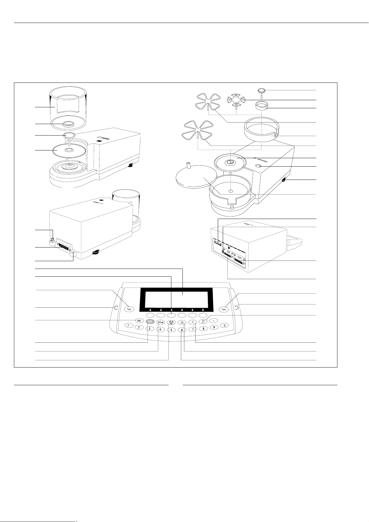
Pos. Designation
1 Weighing pan
2 Filter pan, 50 mm
d
3 Interior draft shield (only for SE2)
4 Optional filter pan, 75 mm d
5 Shield ring
6 Optional filter pan, 90 mm
d
7 Shield disk
8 Level indicator
9 Leveling foot
10 Draft shield cover
11 Female connector for weigh cell
12 DC jack for AC power
13 Communications port (PERIPHERALS)
14 Printer port (PRINTER)
15 Tare key
Pos. Designation
16 Key for opening the draft shield counterclockwise
17 Print key
18 Info key for displaying device information
19 CF key (clear function)
20 Numeric keys
21 Toggle key for changing to the next application program
22 Key for accessing Setup mode (settings)
23 On/off key
24 Toggle key for alphanumeric input
25 Key for opening the draft shield clockwise
26 Function keys
27 Display
28 Lug for attaching antitheft locking device
29 Female connector for evaluation unit
30 Terminal for connecting an equipotential bonding conductor
31 Draft shield
General Views of the Balance
Models ME5 and SE2
1
2
3
4
5
6
7
8
9
10
11
12
13
14
15
17
16
18
19
20
23
24
25
15
28
29
30
7
1
3
31
22
21
27
26
Page 7

The balance consists of a weighing cell, a
draft shield and a display and control unit.
In addition to the choice of power supply,
via AC adapter or external rechargeable
battery pack, your balance also has interface ports for connecting additional
devices, such as a printer, computer, or
universal remote control switch, etc.
The display and control unit is fastened
to the weighing cell. Operation of the
balance follows a uniform “philosophy,”
which is described in this manual.
Where not expressly indicated otherwise,
the uses described in this manual apply to
verified balance versions (indicated by the
suffix “-.0CE” in the model number), as
well as the standard version.
Combination of Several Applications
You can combine the use of various
application programs to meet your more
complicated requirements.
To select application programs one after
the other, press d (toggle function).
Keys
You can operate the balance either by
using the keys on the display and
control unit or from an on-line PC.
This manual describes operation using
the balance keys.
Labeled Keys
These keys always have the function
indicated by their label, but are not
available at all times. Availability of their
functions depends on the current
operating status of the balance and the
menu settings.
Meaning
a Alphabetic keys
Please see section on “Text Input”
e On | off key
Turns the balance on and off
or switches it to the standby mode
o Menu settings
Accesses and exits the Setup menu
d Toggles to the next
application program
c Clear function
Deletes keypad input
Interrupts a calibration and
adjustment routine in progress
Quits application programs
7
Operating Design
ME215/235/254/414/614:
J Turns the ionizer on and off
ME5, SE2:
J Displays device information
r Print key
Outputs displayed values
or data logs to the serial
communications and | or
printer port
. Enters a decimal point
1 ... 9 0 keys
See the section on “Numeric Input”
w Tares the balance
K, O, P Opens | closes the draft shield
Numeric Input
To enter numbers: press
1 … 9 0 .
To store numbers entered: press the
corresponding function key directly
below the soft key label
To delete an entire numeric input digit
by digit: press the c key
Text Input
● To enter numbers:
see the section on “Numeric Input“
● To enter letters or characters:
press the a key
> Letters are displayed in the bottom line
for selection
● To select a different letter:
press the corresponding soft key
to change the letter shown
● To select the letter | character shown:
press the corresponding function key
below the soft key label
> The selected letter is shown on
the display
$ Enter the next letter | character,
if desired, as described above
$ To exit the letter input mode (e.g., if the
last character entered is a letter): press
the a key
● To store a word: press the
corresponding function key (soft key),
such as ID
● To delete an input character by character:
press the c key
● To delete user data: enter . or
a space and save
Page 8
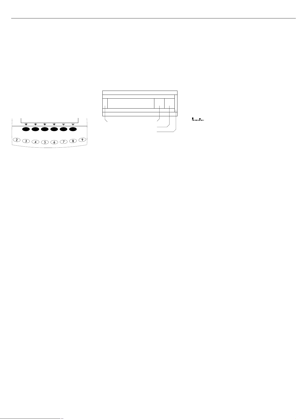
Function Keys (Soft Keys)
The current function of soft keys is
indicated in the bottom line of the display
(footer).
Texts (abbreviations) or symbols can be
displayed.
Texts (Examples)
Cal: Start calibration | adjustment
S ID: Save ID
The function keys are numbered from right
(F1) to left (F6).
Symbols
The bottom line shows the following
symbols:
ooBack to the initial state
(in the Setup menu: exit Setup)
o Go to the higher selection level
O Show sub-items under the active item
Q Move upward in the input |
output window
q Move downward in the input |
output window
l Set the selected menu parameter
There are basically two different
types of displays:
– display for weights and
calculated values
– display for menu parameter
settings (Setup)
F6 F5 F4 F3 F2 F1
Operation
Display for Weights and
Calculated Values
This display is subdivided into 9 areas.
Line for Metrological Data:
When the balance is used in legal metrology,
the following metrological specifications
of the balance are shown here:
Max Maximum capacity (upper range
limit) of the balance
Min Minimum capacity (lower
range limit) of the balance
e Verification scale interval
d Readability | scale interval
On standard balances, only
Max and d
are displayed.
Line for metrological data
Bar graph
Measured value line
Text line
Soft key labels
Plus/minus sign Unit
Stability indicator Tare memory
Calculated value
Application pictograms
Bar Graph:
The bar graph indicates how much of the
balance’s capacity is “used up” by the
current load; during checkweighing, it
indicates the control limits.
The following symbols may be displayed:
0% Lower load limit
100% Upper load limit
Bar graph showing 10% intervals
- Minimum for checkweighing
= Target for checkweighing
+ Maximum for checkweighing
Plus/Minus Sign, Stability Symbol:
A plus or minus sign (F or H) is shown
here for a weight (or a calculated value,
such as that for counting), or the S
symbol indicating that a verified balance
has been zeroed or tared.
Line for Measured Values:
This area shows the weighed or calculated
value and the alphanumeric input.
Unit and Stability:
When the balance reaches stability, the
weight unit or calculated unit is displayed
here.
When the
a symbol is displayed here,
the value indicated in the readout cannot
be used in legal metrology.
8
Operating Design
Page 9
Tare Memory, Calculated Values:
The symbols displayed here indicate when
there is a value in one of the tare
memories or when the value shown is a
result of calculation rather than direct
measurement.
These symbols are as follows:
a Calculated value
s1 Net value | tare memory
s2 used by an application program
(e.g., formulation, second tare
memory)
Application Pictograms:
The pictograms displayed here indicate
the application(s) selected. The pictogram
is displayed inversely (white on a black
background) when the corresponding
application is active.
For example, the following symbols may be
displayed simultaneously:
A The counting application is active
H Checkweighing is also active
S Print
T Data record
Text Line:
Additional information is displayed here
(e.g., operator guidance prompts, name of
the active program, etc.)
Soft Key Labels:
The current functions of the soft keys
above the function keys (arrow keys) are
indicated here; during calibration | adjustment, this line shows up- and down-arrows
(
Q and q) for selecting calibration and
adjustment functions.
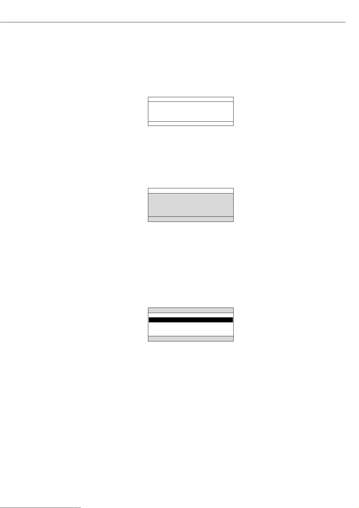
Display for Menu Parameter
Settings (Setup)
This display is divided into three sections.
Status Line:
The status line of shows the function
of the display screen page. In the Setup
menu, the current menu “path” is
shown here.
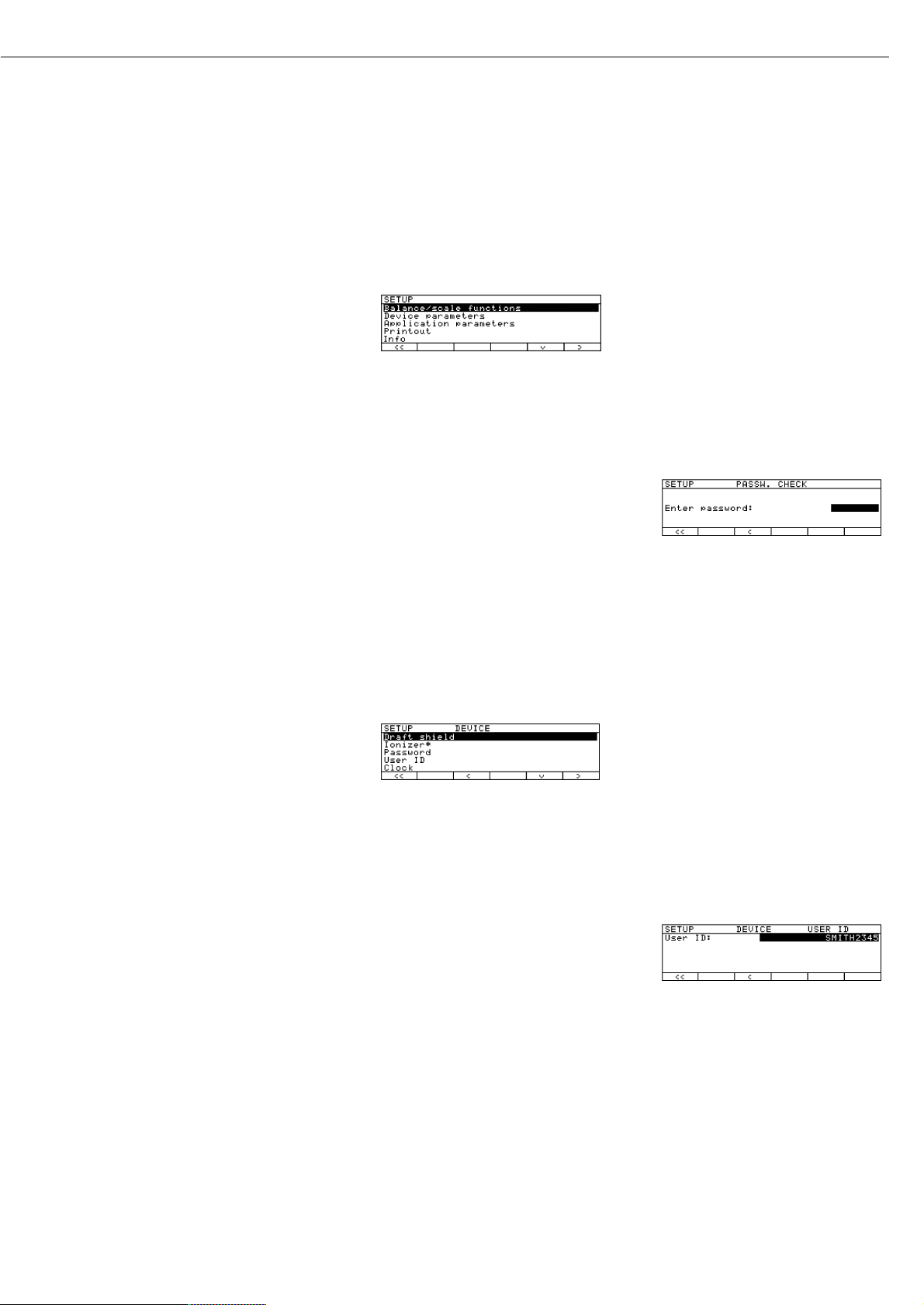
Setup Menu Example: “Balance/scale
functions”:
Input and Output Window
This window contains either detailed
information (e.g., on the active
application) or a pick list. A selected
item is displayed inversely (white
characters on a black background).
You can also enter information in an
active field in this window using the
alphabetic and numeric keys.
Setup Menu Example,
“Device parameters, Adapt filter”:
The following symbol may be displayed
in the input and output window:
d this symbol marks the saved
menu setting
Soft Key Labels
See the description “Function Keys
(Soft Keys)” on the previous page
Minimum vibration
o Normal vibration
Strong vibration
Extreme vibration
SETUP BAL.FUNC.
Line for Operating State
Input and Output Window
Soft key labels
To set a parameter:
● Press the
Q or q soft key repeatedly
until the desired setting is selected
(displayed inversely)
● Confirm your selection:
press the
l soft key
To change the numeric value of
a parameter:
● Press the
Q or q soft key repeatedly,
if necessary, until the desired setting is
selected (displayed inversely)
● Enter a new value or character:
use the 0 1 … 9 . keys
or the a key and enter
the desired letters
● Confirm your selection:
press the l soft key
To exit Setup: press the oo soft key
9
Page 10

Input
Bar Code Scanner or Keyboard Input
You can use a bar code scanner or an
external keyboard to input alphanumeric
values. These inputs are processed in
the same manner as keypad inputs on
the display and control unit of the balance. Bar code and keyboard inputs are
only displayed; they cannot activate any
function.
To assign a bar code scanner or
keyboard input to a function, press one
of the following soft keys:
– Lot
– Samples
– Measured values
– Sample number
– Tare value
– Initial weight
– Backweighed value
– Sample ID
Foot or Hand Switch Input
You can connect a foot switch or
a hand switch to the balance to have
this device perform a keypad
function (such as c or w).
PC Input
You can use a computer to control the
functions of the balance and display
and control unit via the communica-
tions port (see the “Data Output
Function” section in the chapter
entitled “Operating the Balance”).
Data Output
The balance provides two interface
ports for outputting weights, calculated
values and parameter settings:
– Serial communications port
(PERIPHERALS – Serial I/O)
– Serial printer port
(PRINTER – Serial Out)
Serial Printer Port
In addition to Sartorius printers (such as
the YDO03-0CE), you also have the
choice of connecting a remote display
or an external checkweighing display to
the printer port.
You can configure the data output
functions in the Setup menu to meet
your various requirements, including
ISO | GLP requirements.
ISO: International Organization
for Standardization
GLP: Good Laboratory Practice
You can have printouts generated
automatically, or by pressing r;
generation can be dependent on or
independent of the stability or time
parameters.
See the section on “Data Output
Functions” in the chapter entitled
“Operating the Balance” for a detailed
description.
Serial Communications Port
You can connect a PC, a remote display,
an external checkweighing display
or a standard (non-verifiable) printer
to this port.
Request messages are sent via the
interface to initiate functions in the
weighing cell and in the display and
control unit. Some of the functions
generate response messages.
See the section on “Data Output
Functions” in the chapter entitled
“Operating the Balance” for a detailed
description.
Error Codes
If you press a key that has no function,
or which is blocked at a certain point in
an application program, this error is
indicated as follows:
– a double beep is sounded as an acoustic
signal if the key has no function
– a double beep is sounded and the
message “No function” is displayed in
the text line if the key function is not
available at that time
The response to an operator error is
identical in all operating modes. See the
chapter entitled “Error Codes” for a
detailed description.
Storing Settings
Saving Parameter Settings
The settings configured remain stored
in the balance’s non-volatile memory. In
addition, you can reload the factory settings.
Saving Settings
Under “Setup > Device parameters >
password” you can assign passwords in
order to block access to:
– Balance | scale functions
– Device parameters
– Application parameters
– Printout
– Factory settings
10
Page 11
11
Getting Started
Storage and Shipping Conditions
Allowable storage temperature: +5 ...+40°C | +41 ... +104°F
The packaging has been designed to ensure that the balance will not be damaged
even if it is dropped from a height of 80 centimeters (about 32 inches). Do not expose
the balance to extreme temperatures, jolts, impact, vibration or moisture.
Unpacking the Balance
§ After unpacking the balance, check it immediately for any visible damage as a result
of rough handling during shipment
$ If this is the case, proceed as directed in the chapter entitled “Care and Maintenance,”
under the section on “Safety Inspection”
It is a good idea to save the box and all parts of the packaging until you have successfully installed your balance. Only the original packaging provides the best protection
for shipment. Before packing your balance, unplug all connected cables to prevent
damage. The strip of cardboard between the display and control unit and the weighing
platform is important for protecting the equipment during shipment!
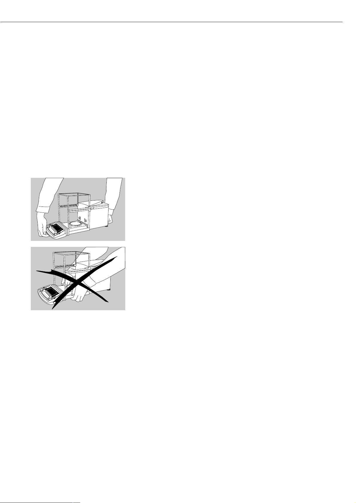
Carrying the Balance
§ To carry the balance, use one hand to support display unit in the front and the other
hand to support the balance housing in the back
! Do not lift the balance by the shield
Equipment Supplied
The following individual components
are supplied:
ME215/235/254/414/614
– Balance
– AC adapter with power cord
– Weighing pan with hanger for below-
balance weighing
– Shield disk
– Dust cover for the balance housing
– Dust cover for the display and control
unit
– Instruction manual
ME5, SE2
– Weigh cell
– Draft shield
– Electronic evaluation unit
– Connecting cable
– AC adapter with power cord
– Accessories kit
The accessories kit includes:
– Weighing pan
– Shield disk
– Interior draft shield (only for SE2)
– Brush
– Forceps
– Cloth
ME5-F, SE2-F
– Weigh cell
– Draft shield cover
– Shield ring
– Electronic evaluation unit
– Connecting cable
– AC adapter with power cord
– Accessories kit
The accessories kit includes:
– Filter pan, 50 mm d
– Weighing pan
– Shield disk
– Interior draft shield (only for SE2)
– Brush
– Forceps
– Cloth
Page 12
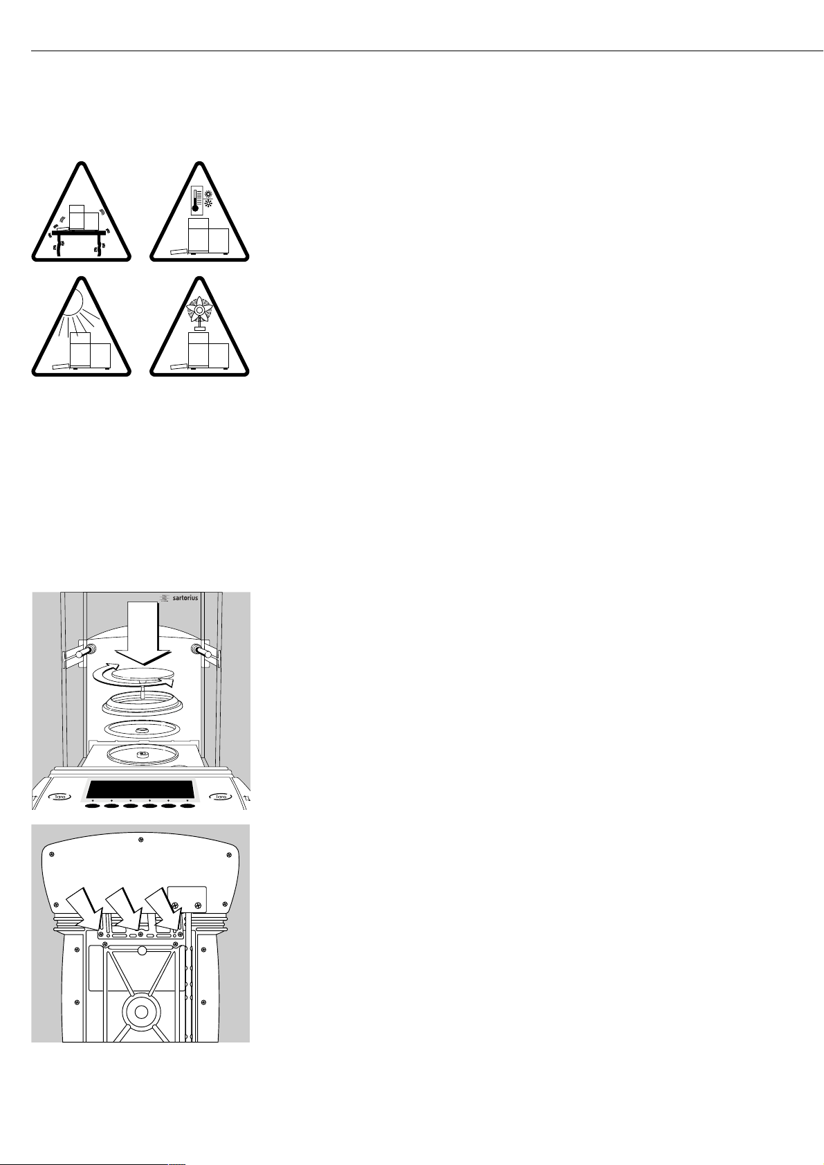
Installation Instructions
The ME/SE balances are designed to provide reliable weighing results under normal ambient
conditions in the laboratory and in industry. Choose the right location to set up your balance
by observing the following so that you will be able to work with added speed and accuracy:
– Set up the balance on a completely even surface on a low-vibration balance table or
wall console
– Avoid placing the balance in close proximity to a heater or otherwise exposing the
balance to heat or direct sunlight, as this can considerably increase the temperature
inside the draft shield (greenhouse effect), resulting in incorrect readouts due
to convection currents, turbulence and buoyancy effects.
– Protect the balance from drafts that come from open windows or doors
– Avoid brief fluctuations in room temperature
– Protect the balance from aggressive chemical vapors
– Do not expose the balance to extreme moisture
Linearization after Transport
After transporting the balance, its linearity may be outside the allowable tolerances
(please refer to the “Specifications” in the “Overview” chapter). After transporting the
balance, be sure to perform internal linearization. Repeat this process to obtain optimal
accuracy. For directions on this procedure, please refer to the section on “Linearization.”
Conditioning the Balance
Moisture in the air can condense on the surfaces of a cold balance whenever it is brought
into a substantially warmer place. If you transfer the balance to a warmer area, make
sure to condition it for about 2 hours at room temperature, leaving it unplugged from
AC power. Afterwards, if you keep the balance connected to AC power, the continuous
positive difference in temperature between the inside of the balance and the outside
will practically rule out the effects of moisture condensation.
Setting Up the Balance ME215/235/254/414/614
§ Place the components listed below inside the weighing chamber in the order given:
– Shield plate
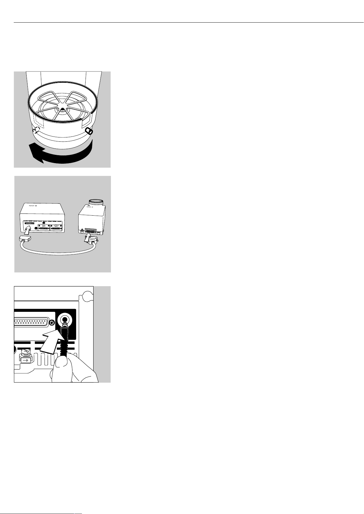
– Position the weighing pan and turn to the left or right until it snaps into place
– Shield disk (ME235S/P only)
$ Note: the shield disk minimizes the effects of drafts within the weighing chamber
Remote Operation of the Display and Control Unit
§ Unplug the cables, turn the balance on its side and lay it on a padded surface
to avoid damaging the weighing system and draft shield
§ Use an Allen wrench to remove the three fastening screws
§ Remove the display unit and attach the connecting cable
> Length of the connecting cable: 44 cm (17 inches)
$ For information on longer cables, please see the “Accessories” section
$ If you wish to use a longer cable, it must be installed by authorized
Sartorius service technicians
12
Page 13
13
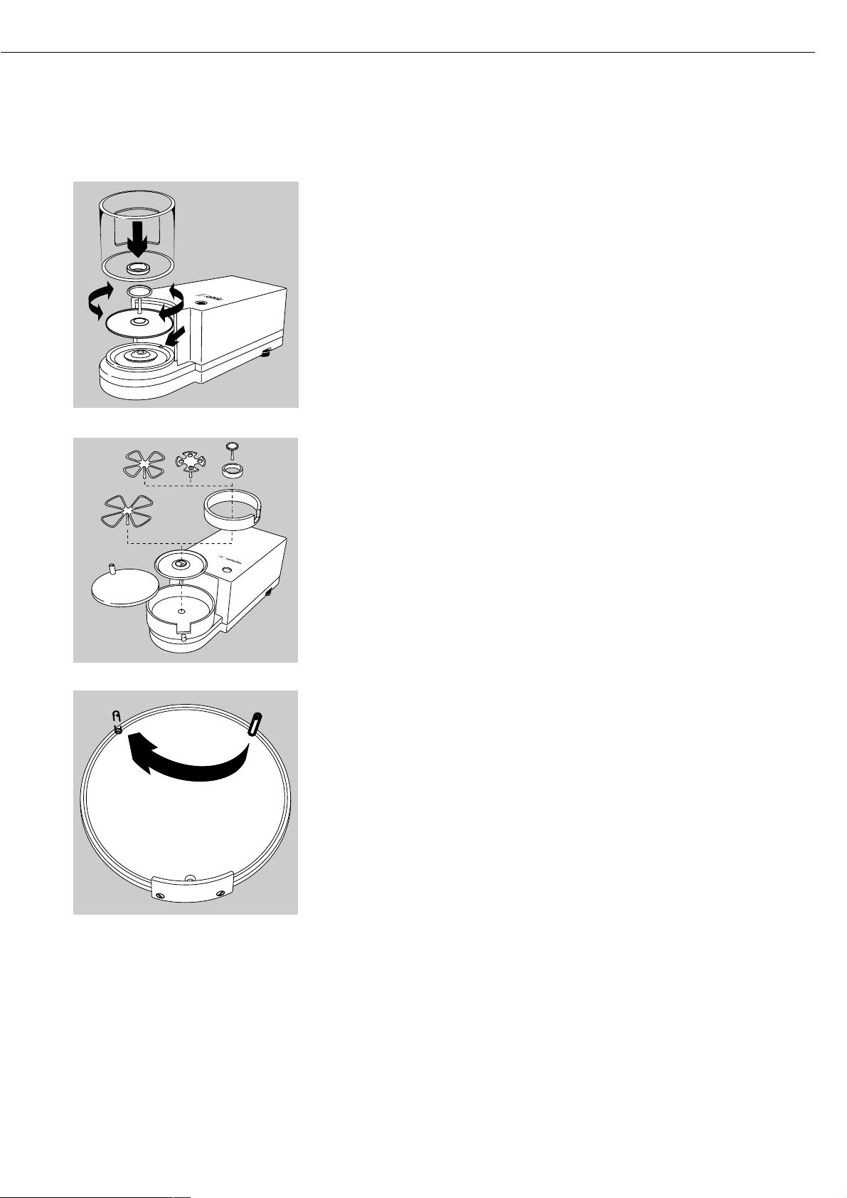
Setting Up the ME5 or SE2 Balance
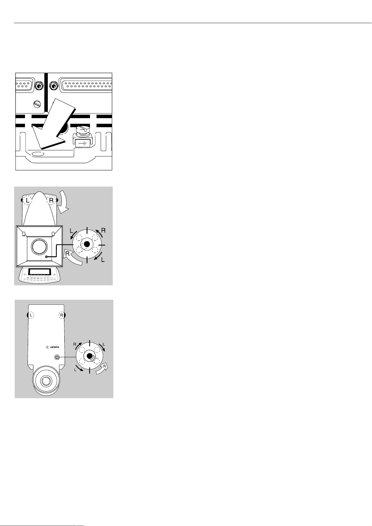
§ Place the components below on the weigh cell base in the order given:
– Shield disk
– Weighing pan
Please note: after placing the weighing pan on the base, turn the pan slightly towards
the left then the right while pressing down on it to lock.
– Interior draft shield (only for SE2)
– Draft shield: center the hole over the pan (see arrows)
Setting Up the ME5-F or SE2-F Balance
§ Place the components below on the weigh cell base in the order given:
– Shield disk
– Interior draft shield ring
– 50 mm dia. filter pan or weighing pan (or, optionally, the 75 or 90 mm dia. filter pan)
Please note: after placing the pan on the base, turn the pan slightly towards the left
then the right while pressing down on it to lock
– Interior draft shield (only for SE2)
! If the weighing pan is removed during operation, turn the balance off and then on again
after you return it to the balance.
– Draft shield cover
Setting Up the Filter Balance for Left-handed Persons:
§ Remove the draft shield cover
§ Detach the pin on the right and re-attach on the left
ME5, SE2:
ME5-F, SE2-F:
Page 14
§ Turn draft shield assembly by approx. 90 degrees toward the left (loosen knurled knob to
turn)
§ Connect the weigh cell to the evaluation unit
– Use a screwdriver to tighten the screws to the female connector on the weigh cell
Connecting the Balance to AC Power
The wide-range AC adapter is designed for 100 V to 240 V.
§ Check the plug design of the power cord
– If it does not fit your wall outlet (mains supply), please contact your
Sartorius office or dealer
Use only
– Original Sartorius AC adapters and power cords
– AC adapters with a registered approval rating from a national testing laboratory
$ To use a main feeder cable from the ceiling or to mount a CEE plug,
have a certified electrician install it
$ To use an external rechargeable battery pack, refer to the “Accessories” in the
“Overview” chapter
§ Insert the AC adapter plug with the angle facing downward into the jack on the balance
14
Page 15

15
§ Plug power cord into the AC adapter
§ To power the balance with AC current, plug the power cord into
a wall outlet (mains supply)
Charging the Rechargeable Battery for Saving Data:
All data is saved in the battery-backed memory. When initially operating the balance,
leave it connected to AC power for one day to charge the battery. When the balance
is disconnected from AC power, the balance-generated data will remain stored for
approximately three months. In the standby mode, data is retained in the memory via
the power supply. Be sure to print out data before storing your balance for a relatively
long period.
Safety Precautions
The AC adapter rated to Class 2 can be plugged into any wall outlet
without requiring any additional safety precautions. The ground or earth terminal is
connected to the scale housing, which can be additionally grounded, if required.
The data interface is also electrically connected to the balance housing (ground).
Note:
This equipment has been tested and found to comply with the limits for a Class A digital
device, pursuant to Part 15 of the FCC rules. These limits are designed to provide
reasonable protection against harmful interference when the equipment is operated in
a commercial environment. This equipment generates, uses and can radiate radio
frequency energy and, if not installed and used in accordance with the instruction
manual, may cause harmful interference to radio communications. Operation of this
equipment in a residential area is likely to cause harmful interference in which case the
user will be required to correct the interference at his own expense. Changes or
modifications not expressly approved by Sartorius AG could void the user‘s authority
to operate the equipment.
Connecting Electronic Peripheral Devices
§ Make absolutely sure to unplug the balance from AC power before you connect or
disconnect a peripheral device (printer or PC) to or from an interface port
Warmup Time
Each time you move your balance to another location, you must condition it for at least
12 hours to the new location. To deliver exact results, the balance must warm up for at
least 12 hours after initial connection to AC power. Only after this time will the balance
have reached the required operating temperature.
Using Balances Verified as Legal Measuring Instruments in the EU*:
$ The balance must warm up for at least 24 hours after initial connection
to AC power
$ Warmup time each time power is turned on the ME614S-0CE, ME414S-0CE: at least 30
minutes
$ Always wait for the power-on adjustment routine to be completed:
for requirements see page 57.
* including the Signatories of the Agreement on the European Economic Area
Page 16
Antitheft Locking Device
To fasten an antitheft locking device, use the lug located on the rear panel
of the balance.
§ Secure the balance at the place of installation, e.g., with a chain
or a lock
Leveling the Balance
Purpose:
– To compensate for unevenness at the place of installation
– To achieve perfectly horizontal positioning of the balance for consistent repeatability
of the weighing results
Always level the balance again any time it has been moved.
Only the 2 front feet are used for leveling.
§ Turn the leveling feet as shown in the diagram until the air bubble is centered exactly
within the circle of the level indicator
> Several leveling steps are usually required
Setting the Language
> See the section on “Setting the Language” in the chapter “Configuring the Balance”
Setting the Date and Time
> See the example on page 17, in the chapter “Configuring the Balance”
16
ME215/235/254/414/614:
MES, SE2:
Page 17
Purpose
You can configure your ME/SE balance
to meet individual requirements by
entering user data and setting
parameters in the Setup menu.
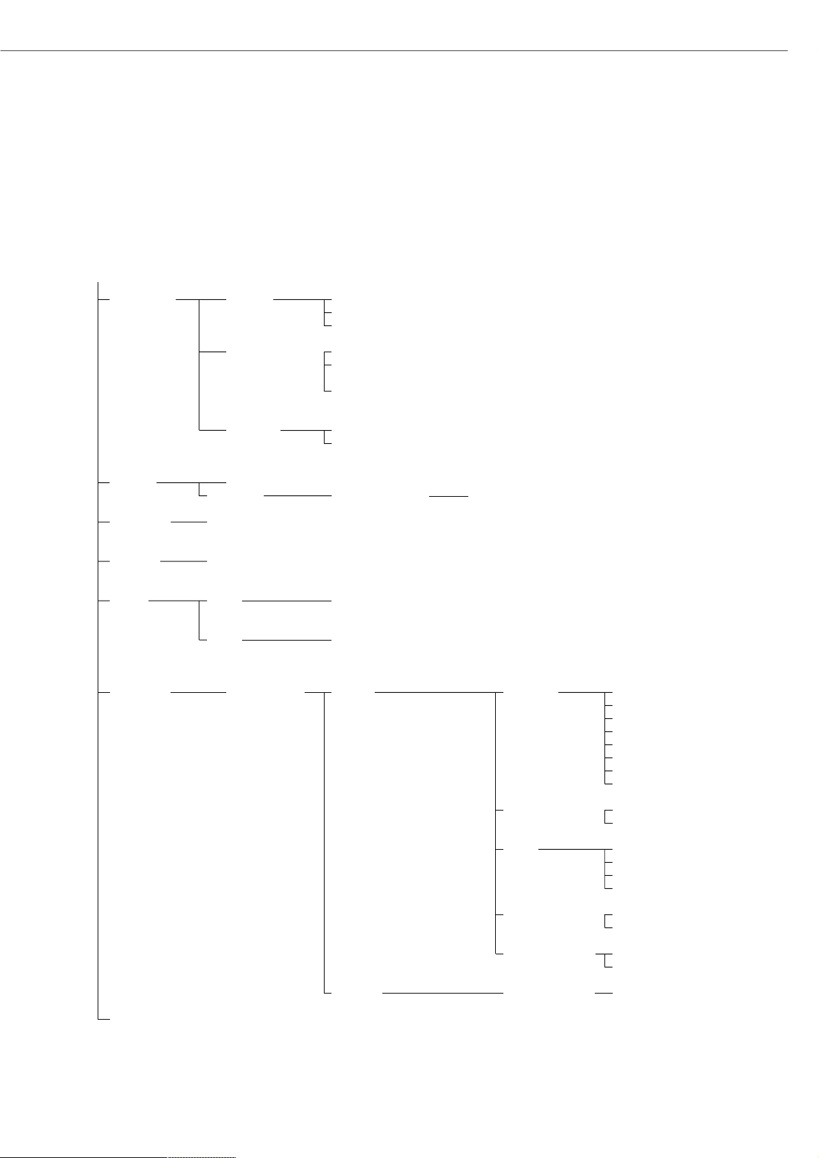
The Setup menu is divided into the
following items:
– Balance/scale functions
– Device parameters
– Application parameters
– Printout
– Device information
– Language
– Factory settings
17
Configuring the Balance
Setting the Language
You can choose from 5 languages for
the information display:
– German
– English (factory setting)
– English with U.S. date | time format
– French
– Italian
– Spanish
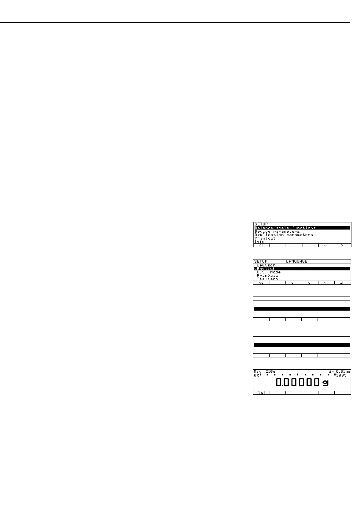
Example: Selecting the Language ”U.S. Mode”
Step Press key(s) (or follow instructions) Display | Printout
1. Select “Setup” menu o
2. Select “Language” Repeatedly
and confirm press
q soft key,
then
O soft key
3. Select “U.S. mode”
q soft key
4. Save language
l soft key
5. Exit the Setup menu
oo soft key
SETUP LANGUAGE
Deutsch
oEnglish
U.S.-Mode
Français
Italiano
oo o q l
SETUP LANGUAGE
Deutsch
English
oU.S.-Mode
Français
Italiano
oo o q l
Page 18
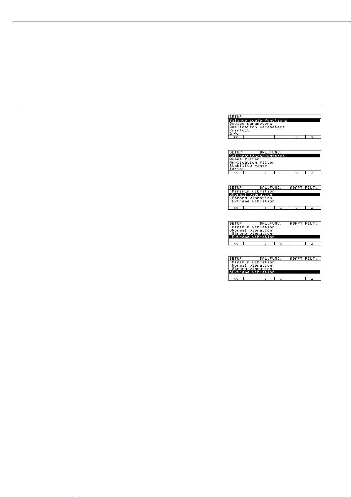
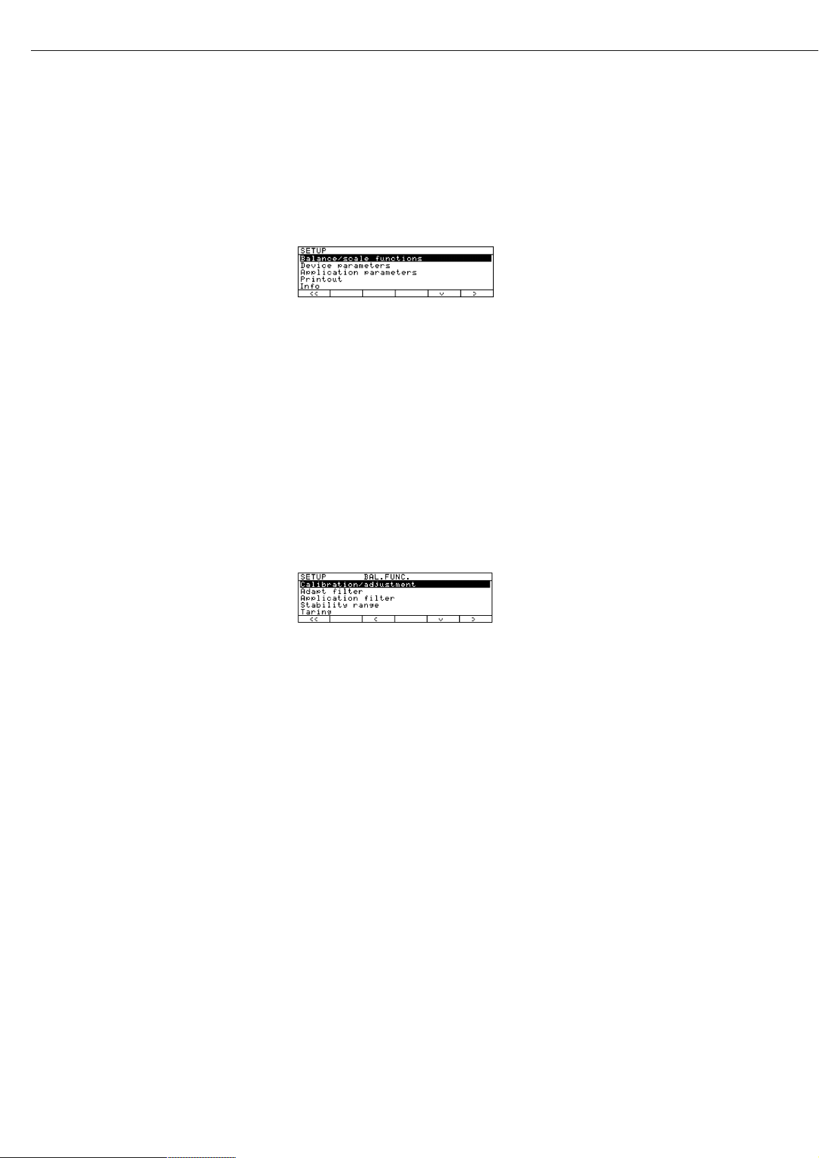
Navigating in the Setup Menu (Examples):
Example: Adapt the balance to “Extreme vibration” by selecting this setting
Step Press key(s) (or follow instructions) Display | Printout
1. Select Setup menu o
2. Confirm “Balance/scale functions”
O soft key
3. Select menu item “Adapt filter”
q soft key, then
and confirm
O soft key
4. Select menu item “Extreme vibration”
q soft key
5. Confirm menu item
l soft key
“Extreme vibration”
6. If required, select further menu items
qQsoft keys
7. Save setting and exit Setup menu
oo soft key
Exiting the Setup Menu
If you use the
oo soft key:
– The software will be restarted if you have changed a setting.
– The software will not be restarted if you have kept the same settings.
In this case, the program will return to its initial state before you press
the o key.
If you press the o key:
– When you exit o, the software is generally restarted.
18
Page 19
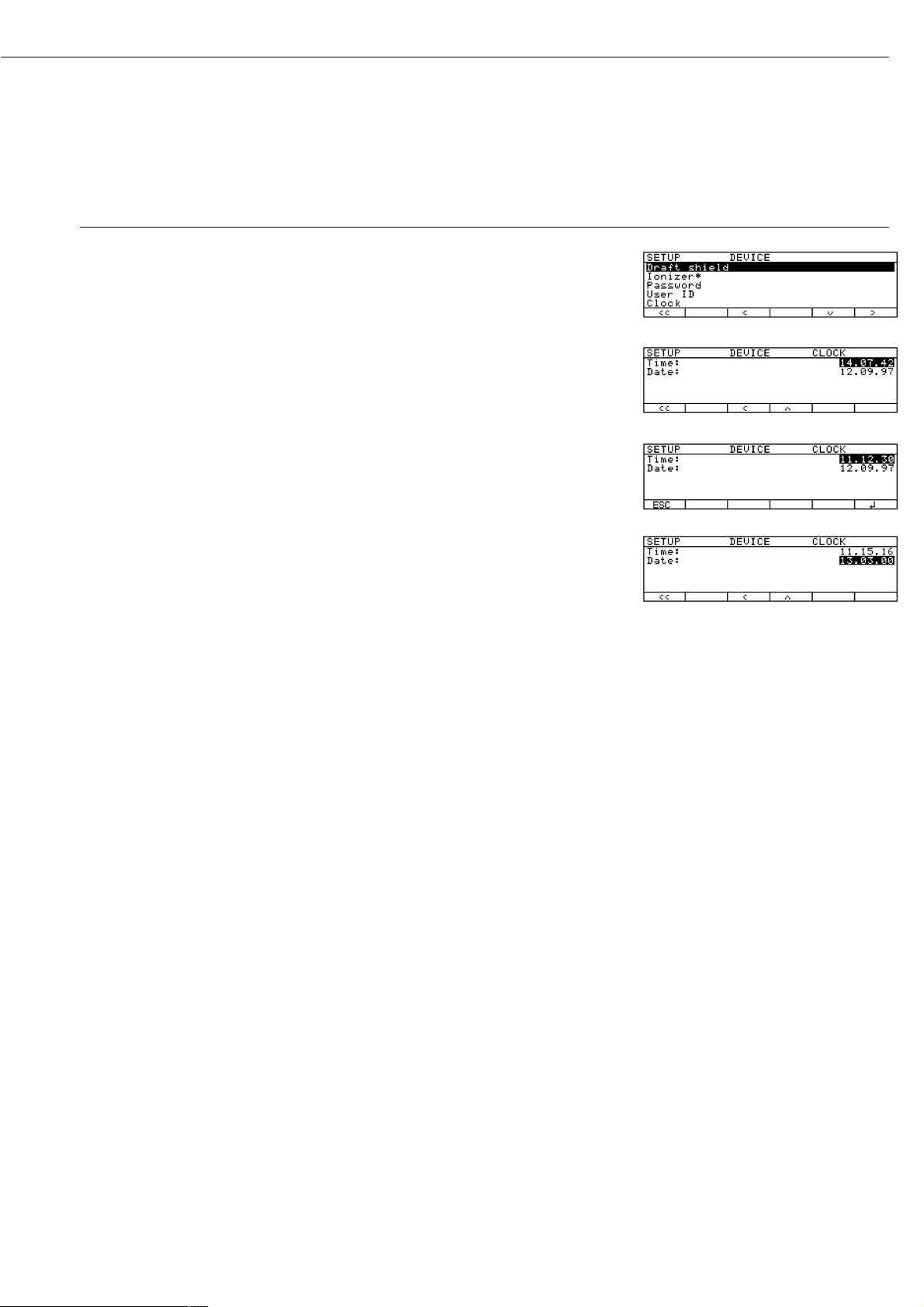
Example: Entering the time and date
Step Press key(s) (or follow instructions) Display | Printout
1. Select Setup menu; o, then
select “Device parameters”
q and O soft keys
2. Set clock press
q repeatedly,
then press
O
3. Enter the time 1 1 . 1 2
. 3 0
4. Set the time according to
your local clock
l soft key
5. Enter the date 1 3 . 0 3
. 00
6. Store the date
l soft key
7. Enter other data, if desired
q Q soft keys
8. Exit Setup menu
oo soft key
* = not on ME5, SE2
19
Page 20
Purpose
This menu item enables you to
configure the balance functions, i.e.,
to meet individual requirements by
selecting predefined parameters in the
Setup menu. You can block access to
the menu by assigning a password.
Features
The balance functions are combined in
the following groups
(1st menu level):
– Calibration | adjustment
– Adapt filter
– Application filter
– Stability range
– Taring
– Auto zero
– Weight unit 1
– Display accuracy 1
– Tare/zero with power on
– Factory settings: only wgh. param. (only
the balance functions)
For legal metrology, the selection
of individual parameters is limited.
Factory Settings
Parameters: The factory settings are
identified by the symbol “o” in the list
starting on page 21.
Preparation
Show available balance functions:
§ Select Setup menu: press the o key
> SETUP is displayed
§ Select “Balance functions”:
press the
O soft key
If you already assigned a password:
> The password prompt is displayed
$ If access is blocked by a password:
enter the password using the numeric |
alphabetic keys
$ If the last character of the password is
a letter: conclude input by pressing a
§ Confirm your password and have
the balance functions displayed:
Press the
l soft key
> Balance functions are displayed:
$ To select the next group:
press the
q soft key (down arrow)
$ To select the previous item of
a group: press the
Q soft key
(up arrow)
$ To select the next sub-item within
a group:
press the
O soft key (right arrow)
$ To select the previous group:
press the
o soft key (left arrow)
$ To confirm: press the
l soft key
Extra Functions
§ Exit the Setup menu:
press the
oo soft key
> Restart your application
§ Print parameter settings:
– When the balance functions are
displayed, press r
> Printout (example)
Texts with more than
20 characters are cut off
SETUP
BAL. FUNC.
--------------------
Calibration/adjustm
CAL/isoTST key fun
Selection mode
Cal/adjustment seq
Calibrate, then auto
adjust
isoCAL function
On without resetting
app.
Start automatic ad
isoCAL
Print GLP/GMP adju
Automatic if GLP is
selected
Parameter for exte
Wt. ID (W ID):
Cal./adj. wt:
200.00000 g
Adapt filter
Normal vibration
Application filter
Final readout
Stability range
2 digits
Auto zero
On
Weight unit 1
Grams /g
Display accuracy 1
All digits
--------------------
20
Setting the Balance Functions (BAL.FUNC.)
Page 21
Balance Functions (Overview)
ο factory setting
√ user-defined setting(s)
Setup Calibration | Cal | isoTST External calibration | adjustment** with
Balance Adjustment key function factory-defined calibration weight
functions External calibration | adjustment**;
user-defined weight
Internal calibration | adjustment
Internal linearization
Cal key blocked
reproTEST
ο Selection mode for cal. | adjustment
Calibration | ο Calibrate, then auto adjust
adjustment sequence Calibrate, then manual adjust
isoCAL function Off
Only adjustment prompt
isoCAL and linearization on
On and reset application
ο On without resetting application
Start automatic User-defined adjustment Enter adjustment time 1: (hh.mm)
adjustment times Enter adjustment time 2: (hh.mm)
Enter adjustment time 3: (hh.mm)
ο isoCAL
Print GLP ο Automatic if GLP is selected
adjustment record On request,
from record memory
Parameter for Weight set ID (W ID): Enter 14 characters max.
external weight Calibration |
adjustment weight: Enter exact weight
Adapt filter Minimum vibration
(ambient ο Normal vibration
conditions) Strong vibration
Extreme vibration
Application filter ο Final readout
Filling mode
Stability range 1⁄4 digit
1⁄2 digit
1 digit
ο 2 digits
4 digits
8 digits*
Taring* Without stability
ο After stability
Auto zero ο On
Off
* = not applicable to verified balances
** = only external calibration is possible for verified balances
21
Factory setting
Factory setting
Page 22
Setup – Weight unit 1 ο Grams | g
Balance Kilograms | kg*
functions Carats | ct
Pounds | lb*
Ounces | oz*
Troy ounces | ozt*
Hong Kong taels | tlh*
Singapore taels | tls*
Taiwanese taels | tlt*
Grains | GN*
Pennyweights | dwt*
# Milligrams | mg
Parts per pound | lb*
Chinese taels | tlc*
Momme | mom*
Austrian carats | K*
Tola | tol*
Baht | bat*
Mesghal | MS*
Display ο All digits
accuracy 1 Fewer for weight change
Last digit off*
Tare | zero with ο On
power on* Off
Factory settings: No
only weighing Yes
parameters
(= balance | scale
functions)
* = not applicable to verified balances
# = factory setting on ME5, SE2
22
Factory setting
Page 23
Purpose
This menu item enables you to
configure the balance, i.e., to meet
individual requirements by selecting
predefined menu parameters in the
Setup menu. You can block access to
the menu by assigning a password.
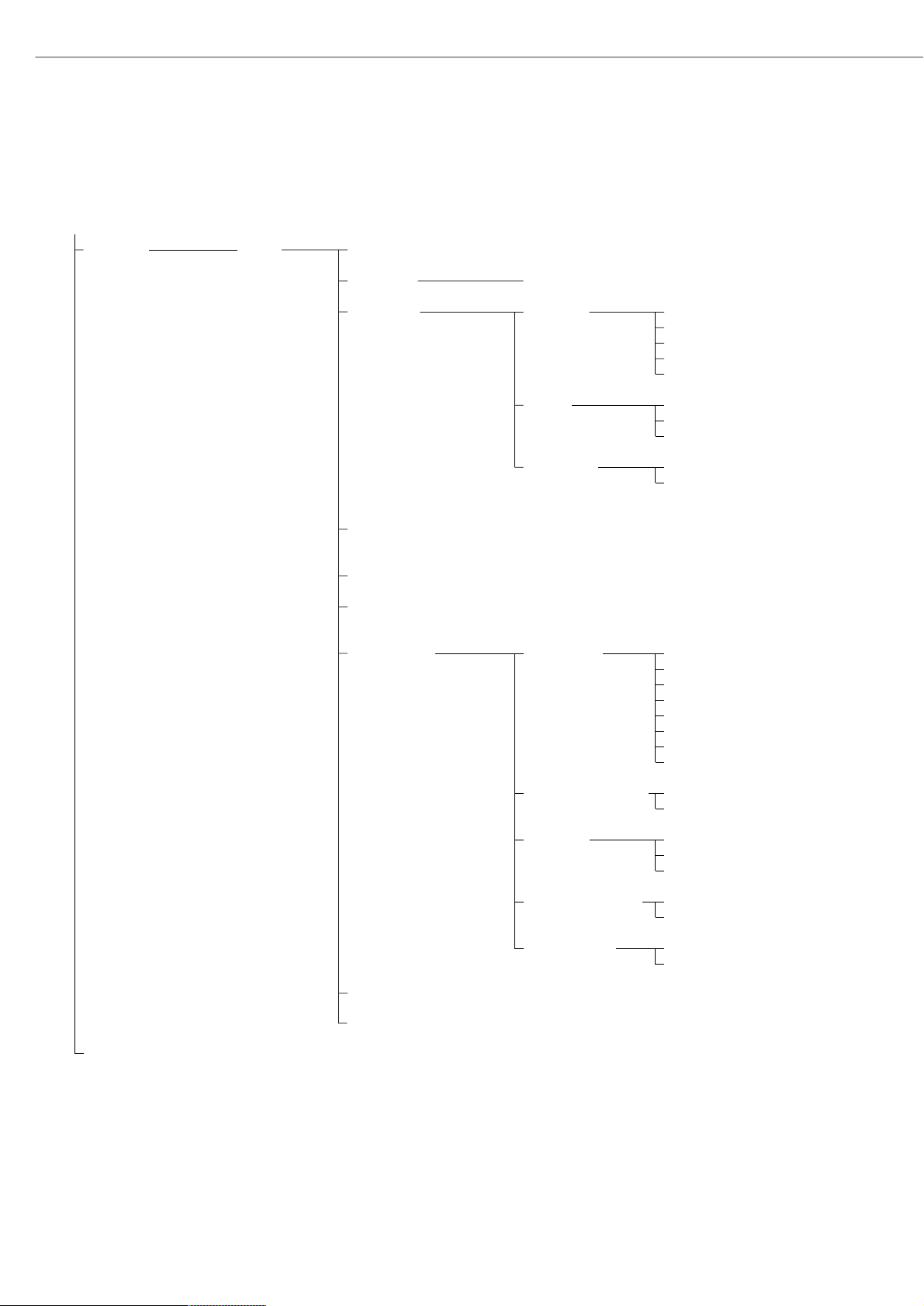
Features
The device parameters are combined in
the following groups
(1st menu level):
– Draft shield
– Ionizer*
– Password
– User ID
– Clock
– Interfaces
– Display
– Keys
– Extra functions
– Factory settings: only device parameters
Factory Settings
Parameters: The factory settings are
identified by the symbol “ο” in the list
starting on page 25.
* = not on ME5, SE2
23
Setting the Device Parameters (Device)
Preparation
Display available device parameters
§ Select the Setup menu:
press o
> SETUP is displayed:
§ Select “Device parameters”:
use the
q and O soft keys
If no password has been assigned,
anyone can access the Setup menu
device parameters
If a password has already been assigned:
> The password prompt is displayed
$ If access is blocked by a password: enter
the password using the numeric and |
or alphabetic keys
$ If the last character of the password
is a letter:
conclude input by pressing
the a key
§ Press l to confirm the password
> Device parameters are now displayed:
$ To select the next group:
press the
q soft key (down arrow)
$ To select the previous menu item
of a group: press the
Q soft key
(up arrow)
$ To select the next sub-item within
a group: press the
O soft key
(right arrow)
$ To select the previous group:
press the
o soft key (left arrow)
$ Press
l to confirm the selected
menu item
Entering or Changing a Password
– Let’s assume that a password with 8
characters max. has already been
assigned to access the Setup device
parameters
§ Select the Setup menu:
press o
> SETUP is displayed
§ Select device parameters:
Use the
q and O soft keys
If you have already assigned
a password:
> The password prompt is displayed:
$ Enter the password
$ Press the
l soft key to confirm
your password and view the device
parameters
§ Write down your password here for easy
reference:
Password = .............................
If you assign a password and then forget what the word is:
$ Enter the General Password
(see Appendix)
$ Press the
l soft key to confirm and dis-
play the password
> The device parameters are displayed
§ Select the device parameter “Password”:
If necessary, repeatedly press
q or Q
and O, until you see
> Password: and any existing password
Page 24

§ New password: Enter the numbers
and/or letters for the new password
(8 characters max.)
If “none” is displayed, this means
no password has been assigned
To delete the user password:
Press . or c and confirm
§ To confirm:
press the
l soft key
§ Exit the Setup menu:
press the
oo soft key
> Restart the application
Extra Functions
§ Exit the Setup menu:
press the
oo soft key
> Restart the application
§ Print the parameter settings:
– If the device parameters
are displayed: press r
> Printout (example)
-------------------SETUP
DEVICE
--------------------
Draft shield
Left/right key
Same function
Automatic mode
Off
Weight resolution
Show all decimal pla
ces
Ionizer
On
Auto-off time:
10 sec
User ID
User ID:
Interfaces
Serial communicati
SBI
Baudrate
1200 baud
Number of data b
7 data bits
Parity
Odd
Number of stop b
1 stop bit
Handshake mode
Hardware handshake
after 1 char
Serial printer (PR
YDP03
Baudrate
1200 baud
Parity
Odd
Handshake mode
Hardware handshake
after 1 char
Function: external
Print key
Function: control
Output
Display
Contrast
2
etc.
24
Page 25
Device Parameters (Overview)
ο factory setting
√ user-defined setting(s)
Setup –
Device
parameters
Draft shield Keys ο Same function
Left/right key Separate function
Off
Automatic mode ο Off
Close –>
function –> open
Close –>
perform function
Weight ο Show all decimal places
resolution Do not show last decimal place
with door open
Ionizer* Off
ο On Auto-off time: 10 s 1 .. 99 seconds
Password:
None
Enter 8 characters
max.
User ID:
None
Enter 20 characters
max.
Clock Time: Enter
hh.mm.ss
Date: Enter dd.mm.yy
or mm.dd.yy (U.S. mode only)
(01.01.97)
Interfaces Serial ο SBI Baud rate 150 baud
communication 300 baud
(PERIPHERALS) 600 baud
ο 1200 baud
2400 baud
4800 baud
9600 baud
19,200 baud
Number of data bits ο 7 bit
1)
8 bit
Parity Space
2)
oOdd
Even
None
3)
Number of stop bits ο 1 stop bit
2 stop bits
Handshake mode Software handshake
ο Hardware handshake,
1 character after CTS
xBPI Network address: ο Enter any number from 0 to 31
For the display, keys and extra functions, see next pages
* = not on ME5, SE2
1)
not if “None” parity is selected
2)
only if 7 data bits selected
3)
only if 8 data bits selected
25
Factory setting
Factory setting
Factory setting
Factory setting
Page 26
Setup –
Device
parameters
Interfaces Serial YDP01IS
printer YDP02 see YDP03 (not with 19,200 baud)
(PRINTER) ο YDP03 Baud rate ο 1200 baud
2400 baud
4800 baud
9600 baud
19,200 baud
Parity Space
ο Odd
Even
Handshake Software handshake
mode ο Hardware handshake,
1 character after CTS
YDP01IS Label
(label printer)
YDP02IS
YDP02IS Label
(label printer)
Universal Baud rate 150 baud
300 baud
600 baud
1200 baud
2400 baud
4800 baud
ο 9600 baud
19,200 baud
Number of data bits 7 bits
1)
ο 8 bits
Parity Odd
Even
ο None
2)
Number of stop bits ο 1 stop bit
2 stop bits
Handshake ο Software handshake mode
Hardware handshake,
1 character after CTS
YDP04IS
YDP04IS Label
For the display, keys and extra functions, see next page
1)
not if “None” parity is selected
2)
only if 8 data bits selected
26
Factory setting
Factory setting
Page 27
27
Setup –
Device
parameters
Interfaces Function: ο Print key r
external switch Tare key
Calibration key
F1 function key
(Right soft key)
Clear function key c
F2 function key
(2nd soft key from the right)
Bar code scanner/
extra keyboard
Ionizer key
Right draft shield key
Left draft shield key
Function: control ports Input
ο Output
Display Contrast Select contrast (0 to 4): 0
1
o2
3
4
Background ο White
Black
Digit size ο 10mm + bar graph + text display
13mm + bar graph
13mm + text display
13mm
Application Off
symbols ο On
Keys CF function ο Clear all applications
in application Clear only selected applications
CF function Delete entire input
for input ο Delete last character
Block key ο All keys unblocked
functions All blocked except
for o, e
Alphanumeric
keys blocked
Extra functions Acoustic signal ο On
Off
Power-on ο Off/on/standby
mode Auto on
Factory settings: No
only Yes
device parameters
Factory setting
Factory setting
Page 28

Purpose
This menu item enables you to
configure the balance, i.e., adapt the
balance to your individual requirements
by selecting from a list of parameter
options in a menu. You can block access
to this menu by assigning a password.
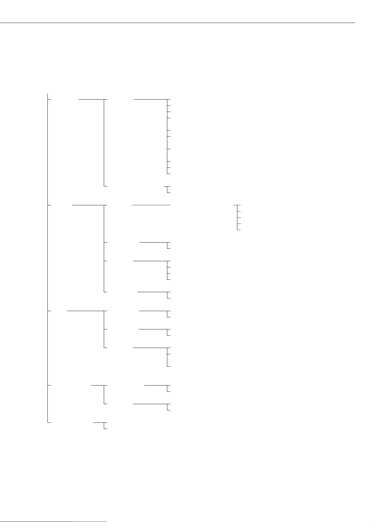
Features
The simple weighing function is
available at all times. You can select one
from each of the following application
groups. This means a
number of combinations are possible.
Application 1 (basic settings)
– Toggle weight units
– Counting
– Weighing in percent
– Animal weighing
(averaging)
– Calculation
– Recalculation
– Density determination
– Differential weighing
– Air buoyancy correction and air density
determination
– Diameter determination
Application 2 (control functions)
– Checkweighing
– Time-controlled functions
Application 3 (data records)
– Totalizing
– Formulation
– Statistics
In addition, you can assign 2 extra
functions to each of the soft keys,
in some cases (depending on the Setup
configuration):
– Second tare memory
– Identification codes
– Manual storage in app.
3 memory (M+ key)
– Changing the resolution
– Product data memory
– SQmin function*
– DKD uncertainty of measurement*
Auto-start application when the balance
is switched on
Factory settings:
only application parameters
Factory Settings for the Parameters
The factory settings are identified by
the symbol “ο” in the list starting on
page 29.
* must be activated by service technician
Preparation
Display available application
parameters:
§ Select the Setup menu:
press the o key
> SETUP is displayed
§ Select parameters: repeatedly press the
q and O soft keys
If you have already assigned
a password:
> The password prompt is displayed:
$ If access is blocked by a password: enter
the password using the numeric/alphabetic keys
$ If the last character of the password is a
letter: conclude input by pressing a
§ Confirm your password and have the
application parameters displayed: press
the
l soft key
> The application menu is displayed:
$ To select the next group:
press the
q soft key (down arrow)
$ To select the previous item of
a group: press the
Q soft key
(up arrow)
$ To select the next sub-item within
a group: press the
O soft key (right
arrow)
$ To select the previous group: press the
o soft key (left arrow)
$ To confirm: press the
l soft key
Extra Functions
§ Exit the Setup menu:
press the
oo soft key
> Restart your application
§ Print parameter settings:
– When the balance/scale functions are
displayed, press r
> Printout (example)
Texts with more than 20 characters are
truncated
SETUP
Application
--------------------
Application 1 (basi
Off
Application 2 (cont
Off
Application 3 (data
Off
Extra function (F4)
Off
Extra function (F5)
Off
Auto-start app. whe
Off
--------------------
28
Setting the Application Parameters (Application)
Page 29
Application Parameters (Overview)
ο factory settings
√ user-defined setting(s)
Setup – Application 1 ο Off (weighing only)
Application (Basic settings)
parameters Toggle wt. units Weight unit 1 ο Grams /g
Kilograms /kg*
Carats /ct
Pounds /lb*
Ounces /oz*
Troy ounces /ozt*
Hong Kong taels /tlh*
Singapore taels /tls*
Taiwanese taels /tlt*
Grains /GN*
Pennyweights /dwt*
# Milligrams /mg
Parts per pound //lb*
Chinese taels /tlc*
Momme /mom*
Austrian carats /K*
Tola /tol*
Baht /bat*
Mesghal /MS*
Display accuracy 1 ο All digits
Fewer for weight
changes
Last digit off*
Weight unit 2 # Grams /g
Kilograms /kg*
Carat s/ct
Pounds /lb*
Ounces /oz*
Troy ounces /ozt*
Hong Kong taels /tlh*
Singapore taels /tls*
Taiwanese taels /tlt*
Grains /GN*
Pennyweights /dwt*
ο Milligrams /mg
Parts per pound //lb*
Chinese taels /tlc*
Momme /mom*
Austrian carats /K*
Tola /tol*
Baht /bat*
Mesghal /MS*
Display accuracy 2 ο All digits
Fewer digits for
weight change
Last digit off*
For counting through air buoyancy correction, see the following pages
Applications 2 and 3 see following pages
* not applicable to verified balances
# = factory setting on ME5, SE2
29
Factory setting
Factory setting
Page 30

Setup – Application 1 Counting Accuracy – Average ο Display accuracy
Application (Basic settings) piece weight calculation + 1 decimal place
parameters (resolution) + 2 decimal places
Average piece Off
weight updating Manual
ο Automatic
Percent weighing Weight storage accuracy ο Display accuracy
(resolution) + 1 decimal places
+ 2 decimal places
Decimal places for None
readout in percent 1 decimal place
ο 2 decimal places
3 decimal places
4 decimal places
5 decimal places
6 decimal places
7 decimal places
Display calculated value ο Residue
Loss
Ratio 1 (DR)
Ratio 2 (OR)
Animal weighing* Animal activity Calm
(averaging) Normal
Active
0.1% of the animal/object
0.2% of the animal/object
0.5% of the animal/object
1% of the animal/object
2% of the animal/object
ο 5% of the animal/object
10% of the animal/object
20% of the animal/object
50% of the animal/object
100% of the animal/object
Start Manual mode
ο Automatic mode
Minimum load for automatic None
storage 10 digits
20 digits
50 digits
ο 100 digits
200 digits
500 digits
1000 digits
Decimal places in None
result display 1 decimal place
ο 2 decimal place
3 decimal places
4 decimal places
5 decimal places
6 decimal places
7 decimal places
Printout None
ο Average weight only
Average and calculated value
Recalculation*
For calculation through air buoyancy correction, see following pages
Applications 2 and 3 see following pages
* = How to run this application is described in detail in our Masterpro “LA….” Installation and Operating Instructions.
Request your copy directly from Sartorius or download it from the Internet (www.sartorius.com; see “download”)
30
Factory setting
Page 31

Setup – Application 1 Calculation Decimal places in None
Application (Basic settings) calculated result 1 decimal place
parameters ο 2 decimal places
3 decimal places
4 decimal places
5 decimal places
6 decimal places
7 decimal places
Density Method Density of liquid
ο Buoyancy
Displacement
Pycnometer
Liquid causing ο Water
buoyancy Ethanol
User-definable
Decimal places None
for disp. of vol./ 1 decimal place
density ο 2 decimal places
3 decimal places
4 decimal places
Printout ο None
All data
Differential weighing Weighing sequence* Individual weighing
Consecutive individual weighing
ο Combined weighing
Serial weighing
Tare weighing No
ο Yes
Result with None
decimal point 1 decimal place
ο 2 decimal places
3 decimal places
4 decimal places
5 decimal places
6 decimal places
7 decimal places
Autosave ο Off
values On, first value at stability
On, last value at stability
On, value bet.
70 – 130% at stabil.
Minimum load None
for autosave 10 digits
ο 20 digits
50 digits
100 digits
200 digits
500 digits
1000 digits
Save statistics ο No
Yes
Air buoyancy correction: See next page
Applications 2 and 3: see following pages
* = Setting can only be changed when the program is initially run and when the Wg.seq. key option is set to “No”
31
Factory setting
Page 32

Setup – Application 1 Differential weighing Generate printout None
Application (Basic settings) ο Automatic after backweighing
parameters Auto. after initial weigh.
and backweighing
Automatic after tare-, initialand backweigh.
Include sample ID in text line ο No
Yes
Wg.seq key No
ο Yes
Clear sample after individual ο No
weight, result + and unload Yes
Last residual weight is stored ο No
as initial weight (ashing) Yes
Air buoyancy correction Air density determination ο No
Yes
Change steel/aluminum ο No
references Yes
Diameter determination
Application 2 ο Off
(Control functions) Checkweighing* Activation of port lines ο Within checkweighing range
Always on
Stability and
checkweighing range
At stability
Stability + checkweigh.
range on
Type of checkweighing input ο Target, min., max. weight
Minimum, maximum weight
Target, min. in %, max. in %
Weight display mode ο Absolute value
Difference from the target
Automatic printout Yes
of OK values ο No
Time-controlled Function after time interval Beep (acoustic signal)
functions Lock in readout
ο Automatic printout of values
Store value in applicat. 3 memory
(totalizing, formulation, statistics)
Automatic function restart ο On
Off
Storage mode ο Without stability
After stability
After higher stability
Print then tare Off
ο On
* = How to run this application is described in detail in our Masterpro “LA….” Installation and Operating Instructions.
Request your copy directly from Sartorius or download it from the Internet (www.sartorius.com; see “download”)
32
Factory setting
Factory setting
Page 33

Setup – Application 3 ο Off
Application (Data records)
parameters Totalizing* Automatic storage ο Off
On, first value at stability
On, last value at stability
On, value bet. 70% – 130%
at stability
Minimum load for None
automatic storage 10 digits
ο 20 digits
50 digits
100 digits
200 digits
500 digits
1000 digits
Source of data for auto storage ο Application 1
Application 2
Evaluated values ο Net
Calculated
Net + calculated
Evaluation mode, MR function ο Intermediate evaluation, print
Final evaluation, print
Intermediate evaluation,
display+print
Final evaluation,
display+print
M+/M– function, then tare ο Off
On
Printout of individual No
components ο Yes
Formulation* Automatic storage ο Off
On, first value at stability
Minimum load for None
automatic storage 10 digits
ο 20 digits
50 digits
100 digits
200 digits
500 digits
1000 digits
Source of data for ο Application 1
automatic storage Application 2
Evaluated values ο Net
Calculated
Net + calculated
Evaluation mode, MR function ο Intermediate evaluation, print
Final evaluation, print
Printout of individual No
components ο Yes
* = How to run this application is described in detail in our Masterpro “LA….” Installation and Operating Instructions.
Request your copy directly from Sartorius or download it from the Internet (www.sartorius.com; see “download”)
33
Factory setting
Factory setting
Page 34

Setup – Application 3 Statistics Automatic storage o Off
Application (Data records) On, first value at stability
parameters On, last value at stability
On, value 70% – 130%
at stability
Minimum load for None
automatic storage 10 digits
o 20 digits
50 digits
100 digits
200 digits
500 digits
1000 digits
Source of data for o Application 1
automatic storage Application 2
Evaluated values o Net
Calculated
Net + calculated
Evaluation mode, o Intermediate evaluation, print
MR function Final evaluation, print
Intermediate evaluation,
display + print
Final evaluation,
display + print
M+/M– function, then tare o Off
On
Printout of individual No
components o Yes
Extra Functions – for other extra functions, see next page
34
Factory setting
Factory setting
Page 35

Setup – Extra Functions ο Off
Application F4 key
parameters Extra Functions 2nd tare memory Container tare weight ο No
F5 key Yes
Automatic printout Net value
Tare/preset tare
ο Off
Identification Printout Automatic, if configured
codes Once after pressing r
(IDs) if configured
ο Each time the print key
(r) is pressed
Once for
M+ function
(application 3 memory)
Manual storage
in app. 3
memory M+ (totalizing,
formulation, statistics)
Changing the resolution
Product data memory
SQmin Function Display o Text display
Bargraph
Print in o Off
GLP Header On
DKD uncertainty Display
1)
U (absolute)
of measurement U* (relative)
PG (process accuracy)
Print
1
) U (absolute)
U* (relative)
PA (process accuracy)
Process accuracy Input: 1–100,
5 decimal places
Auto-start On
application when ο Off
power goes on
Factory settings No
only for Yes
applicationparameters
1)
an asterisk (*) indicates an activated menu item. You can select up to 3 items.
35
Factory setting
Page 36

Purpose
This menu item enables you to
configure the printout to meet your
individual requirements by selecting
predefined menu parameters in the
Setup menu. Printouts of weights and
other measured or calculated values and
IDs enable you to document your data.
You can select the particular data you
wish to print. To prevent changes to
your settings, you can block access to
the menu by assigning a password.
Features
The device parameters are combined in
the following groups
(1st menu level):
– Application-defined output
– Automatic output of displayed values
– Output to interface ports
– Line format
– ISO/GLP printout
– Identification # (identifier)
– Factory settings – only printout
Factory Settings
Parameters: The factory settings
are identified by the symbol “ο” in
the list on the next page.
Preparation
Display available printout parameters
§ Select the Setup menu:
press o
> SETUP is displayed:
§ Select ”Printout”:
use the
q and O soft keys
If no password has been assigned,
anyone can access the printout
parameters in the Setup menu
If a password has already been assigned:
> The password prompt is displayed
$ If access is blocked by a password: enter
the password using the numeric and/or
alphabetic keys
$ If the last character of the password
is a letter: conclude input by pressing
the a key
§ Press
l to confirm the password
> Printout parameters are now displayed:
$ To select the next group:
press the
q soft key (down arrow)
$ To select the previous item of
a group: press the
Q soft key
(up arrow)
$ To select the next sub-item within
a group: press the
O soft key (right
arrow)
$ To select the previous group:
press the
o soft key (left arrow)
$ To confirm: press the
l soft key
Extra Functions
§ Exit the Setup menu:
press the
oo soft key
> Restart your application
§ Print parameter settings:
– When the printout parameters
are displayed, press r
> Printout (Example)
-------------------SETUP
PRINTOUT
--------------------
Application-defined
Stability paramete
With stability
Print on request t
Off
Auto print upon in
All values
Configured printou
Indiv.: Printout
Automatic output of
Stability paramete
Witout stability
Stop auto print
Not possible
Time-dependent aut
1 display update
Output to interface
Serial communicati
Application-defined
output
Serial printer (PR
Application-defined
output
Line format
For other apps/GLP (
22 characters)
ISO/GLP/GMP printou
Off
Identification #
Lot (L ID):
ID1:
ID1
etc.
36
Selecting the Printout Function (Printout)
Page 37

Printout Parameters (Overview)
ο factory setting
√ user-defined setting(s)
SETUP Application- Stability parameter Without stability
1)
Printout defined output o With stability
Print on request, then tare o Off
On
Auto print upon Off
initialization o All values
(of the application) Only main values
Configured printout See own chapter starting
on the next page
Automatic Stability parameter o Without stability
output At stability
of displayed Automatic after
value weight change
2
)
Stop auto print Use print key
r
o Not possible
Time-dependent o 1 display update
auto print 2 display updates
10 display updates *
100 display updates *
Output to Serial communication Off
interface ports (PERIPHERALS) o Application-defined output
Automatic output of displayed value
Serial printer) Off
(PRINTER) o Application-defined output
Line format For raw data (16 characters)
o For other apps/
GLP (22 characters)
ISO/GLP o Off
printout Only for calibration/adjustment
Always on
Identification # Lot ID (L ID): Enter 20 characters max.
ID1: ID1
ID2: ID2
ID3: ID3
ID4: ID4
Factory settings: No
printout only Yes
* = changing settings not applicable to verified balances
1)
= Information on use in legal metrology: Only permitted for control purposes; printouts are not allowed
2)
= auto print when load change is > 10 d and stability is reached: no printout until residual difference in load value is < 5 d
37
Factory setting
Factory setting
Page 38

Purpose
This menu item enables you to
configure individual printout formats.
With the formulation, totalizing and
statistics application, you can also
define the values to be included on
the total printout when the MR key
is pressed.
Under “Setup > Printout > Applicationdefined output > Configured printout”,
you can configure individual, component or total data records that contain
the items in each application that are
available for printouts. Configure these
printouts after you have configured the
applications, because some entries in
the data record depend on the particular application.
Features
– Maximum items in a data record: 60
– Separate configuration of printout
formats for individual weights,
components, total, backweighing and
statistics
– Individual printout generation:
press the r key
Automatic printout of application data:
e.g., results from animal weighing or
density application (Setup menu: Application 1: Density: Printout: All data) OK
values from checkweighing application,
time-controlled printouts, 2nd tare
memory
– Component printout:
For results from totalizing, formulation
or statistics applications, press
M+ or M- (Setup: Application 3: ...,
Printout of individual components: On)
– Total printout: For totalizing,
formulation or statistics applications,
press
MR
– Backweighing printouts or records:
automatically generated after backweighing or manually by pressing the
r key when the result is displayed
at the end of backweighing
– Statistics printout or output:
To generate, press the r key when
the statistics are displayed
Printouts for Differential Weighing:
These printouts can be generated as
standard or configured (user-defined)
reports.
You can configure the following
printouts:
– Individual printout
– Backweighing printout
– Statistics printouts
Printouts are generated in one of
two ways:
– at the request of the user by pressing
the r key (print on request)
– automatically, if configured
in the Setup menu [Application
parameters: Application 1: Differential
weighing: Generate printout: Auto]
You can turn off automatic printout
generation in the Setup menu
[Application parameters:
Application 1: Differential weighing:
Generate printout: None]
– Data records are deleted after you haved
switched to a different application or
activated or de-activated an extra
function in the application parameters
of the Setup menu
– A new pick list for a data record is
created based on the currently active
application programs and extra
functions
– Printout items can be deleted
individually
– No printout is generated when the
following setting is configured:
Setup: Printout: Line format:
For raw data (16 characters)
– Print item “Form feed” for footer:
Advance to beginning of next label in
the “YDP01IS-Label” and “YDP02ISLabel” [printer] interface mode
Extra Functions
§ Exit printout configuration:
press
oo soft key
> Restart application
Printing “Select” and “List” Settings
–
LIST: print the currently selected list
SELECT: printout items that can still
be selected
§ When the select bar is on
LIST or SELECT:
press the r key
> Printout (Example)
BACKW. PRINT.LIST
====================
Sample date
Net initial wt.
Backweighed res
Loss in %
====================
etc.
38
Printout Configuration
Page 39

39
Example:
Configure an Individual Printout for Counting Application to Include Dotted Line, Date/Time, Piece Count and Net Weight
Settings (changes in the factory settings required for this example):
Setup: Application parameters: Application 1: Counting
Exit the Setup menu: press the
oo soft key
Then call Setup again: Printout: Application-defined output: Configured printout
Step Press key(s) (or follow instructions) Display/Output
1. Select Setup menu, o, then
then “Printout”
q repeatedly and
O soft key
2. Confirm “Application-defined
O soft key
output”
3. Select and confirm
q soft key 3x and
“Configured printout”
O soft key
4. Confirm “Indiv. printout”
O soft key
5. Select “Blank line”
O, q, l soft keys
6. Select “Date/time”
q soft key twice, then
l soft key
7. Select “Piece count”
q soft key repeatedly,
then
l soft key
8. Select “net weight”
Q soft key repeatedly,
then
l soft key
9. Exit “Printout” configuration
oo soft key
10. Perform weighing operations, r
then print
--------------------
14.01.2000 09:19
Qnt + 598 pcs
N + 2003.13 g
Page 40

Purpose
This menu item enables you to have
information displayed about the specific
balance (“device”).
Display Device Information on
ME215/235/254/414/614
§ Select the Setup menu:
press the o key
> “SETUP” is displayed:
§ Select “Info”:
Repeatedly press the
q soft key, then
press the
O soft key
§ Select “Device information”:
press the
O soft key
> Device information is displayed:
Display Device Information
on ME5 or SE2
§ Select “Device Information”:
Press the J key
> Device information is displayed
oo o q
SETUP INFO
Version no: 01-41-05
Wgh.sys. ver. #: 00-21-09
Draft sh. ver.#: 05-01-03
Model: ME215S
Serial no: 91205355
§ Print device information:
Press the r key
> Printout (Example)
--------------------
23.12.2001 13:02
Model ME215S
Ser. no. 91205355
Ver. no. 01-41-05
(Version of the operating program)
ID BECKER123
(User ID)
-------------------L ID LOT 23
(Lot ID)
SETUP
INFO
-------------------Version no.:
01-41-05
(Version of the operating program)
Wgh. sys. ver. #:
00-21-09
(Version no. of the weighing cell)
Dft. shield v. no.:
05-01-03
(Program version no. of the
draft shield)
Model:
ME215S
Serial no.:
91205355
Next mainten.:
01.01.2003
Service phone:
00495513080
SQmin:
0.0300 g
--------------------
§ Return to SETUP overview:
press the
o soft key
§ Exit Setup menu:
Press the
oo soft key
> Original settings are restored
Factory Settings
Each parameter category has a factory
setting. In the Setup menu, you can
restore all factory settings by confirming
the selection
YES.
The following settings are not restored:
– Language
– Password
– Display contrast
– Time (clock)
40
Device Information
Page 41

Basic Weighing Function
Purpose
The basic weighing function is always
accessible and can be used alone
or in combination with an application
program (Toggle between Weight Units,
Counting, Weighing in Percent, etc.).
Features
– Taring the balance
– Assigning IDs to weights
– Printing weights
– Printing ID codes for weights
Soft Key Functions
Cal Start calibration/adjustment
isoCAL Press when necessary to
start calibration and
adjustment
S ID Stored ID entered
General Instructions for “Analytical Weighing”
Handling Samples and Containers
The sample should be conditioned
to the temperature inside the balance.
This is the only way to avoid errors
caused by air buoyancy and deviations
caused by convection currents at the
surface of the sample.
Since these effects increase proportionally to the volume and surface of the
sample, make sure that the size of the
tare vessel selected is appropriate for
the initial sample.
Never use your bare hands to touch
samples to be weighed. In addition to
the effect of the temperature, the
extremely hygroscopic behavior
of fingerprints left on the sample will
otherwise cause considerable interference during weight measurement.
Use forceps or a similar utensil that is
appropriate to place your sample carefully on the pan. Working with your
balance requires a steady hand and a
smooth, uninterrupted technique.
If the weighing chamber has not been
opened for a relatively long period,
it may have a temperature different
from that of the balance’s surrounding
environment. When you open the
weighing chamber, a change in temperature will inevitably occur, due to the
laws of physics, and may show up as
a change in the weight readout.
41
Operating the Balance
Therefore, we recommend that before
you begin the actual weighing series you
open and close the weighing chamber at
the same rate as you will be doing during
weighing. After the weighing chamber
has been closed, the weight readout will
usually stabilize after about 8 seconds.
The accuracy of the weight readouts will
increase as you continue weighing with
greater consistency.
Weighing Electrostatically Charged
Samples and Containers
Major measuring errors can occur when
electrostatically charged samples and
containers are weighed. This problem
particularly involves samples that have
extremely poor conductivity (glass, plastic,
filters) since they can discharge electrostatic – i.e., friction-induced – charges only
over a relatively long period of time. The
result is an interaction of forces among the
charges adhering to the sample and the
stationary components of the balance
(weighing chamber base plate, draft shield
construction, balance housing). This is
noticeable when the weight readout drifts.
At high humidity, this effect is not
very pronounced or may not occur at all,
due to the thin layer of water that
condenses on the sample and, through
conductive discharge, counteracts
interfering static electricity.
In addition to taking purely mechanical
counteractive measures (protecting the
sample using a special antistatic weighing
pan – see the “Accessories”), you can
neutralize the surface charges by
“bombarding” them with ions of the
opposite polarity (see page 47 for
instructions on activating the ionizer). This
is a highly effective procedure
for eliminating static electricity.
The balance’s environment, including the
operator, can considerably interfere with
weighing results, due to static electricity.
The balances of the ME/SE series have
been designed to counteract this phenomenon: the glass surfaces of the draft shield
have a special metallic coating.
The rear panel of the balance has a
terminal for connecting an equipotential
grounding conductor. It is used for
additional grounding of a peripheral
device (for example, a vibrating spatula).
This terminal is designed for single
grounding wires up to .25” standard
gauge or 6 mm
2
stranded wires and for .18”
standard gauge or 4mm
2
stranded wires.
Weighing Magnetic or Magnetizable
Samples
It is technically impossible to avoid the use
of magnetizable materials in the manufacture of balances. Ultimately, the operating
principle of high-resolution balances is
based on electromagnetic force compensation of the load placed on the weighing
pan.
When magnetic or magnetizable samples
or containers (e.g., a beaker with a stirrer)
are weighed, interactions among the
above-mentioned components of the balance may occur, distorting weight
readouts.
Unlike deviations caused by electrostatic
charges, magnetic interference is usually
constant over time. However, it is sensitive
to and dependent on the position of the
sample container on the weighing pan and
is also characterized by poor repeatability.
To reduce the effect described above,
we recommend increasing the distance
between the sample and the weighing pan
by inserting a non-magnetizable material
between them (the reduction in force is
proportional to the quadrate of the distance).
In special cases, soft-magnetic plates
should be used to shield against interfering
magnetic effects.
In the presence of extremely strong magnetic fields – for instance, when measuring
the susceptibility of a sample in an electromagnet – you should use the below-balance weighing port, which comes standard
on your balance.
Page 42

Below-Balance Weighing
A below-balance weighing hanger is located on the bottom of the balance.
Not allowed in legal metrology applications
● Open cover plate (1) on the bottom of the balance
● Lift off weighing pan 2
● Unscrew hanger 3
● Insert opposite end of hanger 3 into port and refasten
● Place weighing pan 2 back on balance
● Hang sample on the notched hook
§ Remove both screws from beneath the weigh cell and detach the cover
§ Attach a wire to the sample, if necessary, and hang it on the notched hook
$ If necessary, install a shield for protection against drafts
Preparation for Operation
● Turn on the balance: press e
> The Sartorius logo is displayed
$ If it is time for the next maintenance, the following appears:
To exit this screen: press the
oo soft key
$ Call your nearest Sartorius Service Center to schedule a maintenance appointment
$ To tare the balance, if desired, press w
> The S symbol is displayed when a verified balance is zeroed or tared (±0.25 digit)
42
Operating the Balance
1
ME215/235/254/414/614:
ME5/SE2:
2
3
Page 43

Additional Functions
In addition to the functions:
– alphanumeric input
– taring (not during
alphanumeric input)
– printing
you can also access the following func-
tions from the weighing application:
– calibration/adjustment (not during
alphanumeric input)
– setup
– turning off the balance
43
Calibration
● Press the
Cal soft key
> See the section on “Calibration/Adjust-
ment” for further instructions
Setup
● Press o
> See the chapter entitled “Configuring
the Balance” for further instructions
Turning Off the Balance
● Press e
> The balance shuts off
> The display goes blank
Examples
Example W1: Simple weighing
Step Press key(s) (or follow instructions) Display/Output
1. If necessary, tare the balance w
(S symbol: balance is tared
– verified balances only)
2. Enter sample ID see example W2
3. Determine sample weight Place sample on balance
(example)
4. Print weight r
g
Max 210 g
0%
A
H
L
S
T
d=0.01mg
100%
11223156
F
S
a
s
Cal
S ID ABC123
N +112.23156 g
For Service:
Using Verified Balances as Legal
Measuring Instruments in the EU*:
This balance is not allowed to be used
for weighing goods intended for direct
sale to the public. The type-approval
certificate for verification applies only
to non-automatic weighing instruments; for operation with or without
auxiliary measuring devices, you must
comply with the regulations of your
country applicable to the place of
installation of your balance.
● Before using the balance as a legal
measuring instrument, calibrate and
adjust it at the place of use: see the section on “Calibration, Adjustment” in
this chapter
$ The temperature range (°C) indicated on
the verification label may not be
exceeded during operation.
Example:
BE BK 100
k 0…+40 °
* including the Signatories of the Agree-
ment on the European Economic Area
Max 210 g
0%
S
Cal
000000
d=0.01mg
100%
g
Page 44

Example W2
Enter “ABC123” as the sample ID
Note:
– The sample ID generally applies to one weighing operation only
– The ID is deleted after data output
Step Press key(s) (or follow instructions) Display/Output
Initial state (balance unloaded)
(ID can also be entered while
balance is loaded)
1. Select alphabetic input a
2. Select the required letter group “A”
ABCDEF soft key
3. Enter the letter “A”
A soft key
(To delete a letter: c, c)
4. Select the letter group and
ABCDEF soft key
enter “B”
B soft key
5. Select the letter group and
ABCDEF soft key
enter “C”
C soft key
(If you enter only letters,
conclude input a)
6. Enter the numbers 1, 2 and 3 1 2 3
7. Store the ID
S ID soft key
(20 characters max.)
– The next printout will include
the sample ID
44
Max 210 g
0%
A
H
L
S
T
d=0.01mg
100%
F
S
a
s
ABCDEFGHIJKLMNOPQRSTUVWXYZ/=-?:#*"&U
OOOg000000
Max 210 g
0%
A
H
L
S
T
d=0.01mg
100%
F
S
a
s
ABCDEF
OOOg000000
Max 210 g
0%
A
H
L
S
T
d=0.01mg
100%
F
S
a
s
ABCDEFGHIJKLMNOPQRSTUVWXYZ/=-?:#*"&U
A
Max 210 g
0%
A
H
L
S
T
d=0.01mg
100%
F
S
a
s
ABCDEFGHIJKLMNOPQRSTUVWXYZ/=-?:#*"&U
AB
Max 210 g
0%
A
H
L
S
T
d=0.01mg
100%
F
S
a
s
ABCDEFGHIJKLMNOPQRSTUVWXYZ/=-?:#*"&U
ABC
Max 210 g
0%
A
H
L
S
T
d=0.01mg
100%
F
S
a
s
S ID
ABC123
Max 210 g
0%
S
Cal
000000
d=0.01mg
100%
g
Max 210 g
0%
S
Cal
000000
d=0.01mg
100%
g
Page 45

Opening and Closing the Draft Shield
Purpose
The ME/SE balance is a high-resolution
weighing instrument. It has a draft
shield so that convection currents cannot affect the weighing result. To load a
sample on and remove it from the
weighing pan, a draft shield door must
be opened and closed. You can do this
in various ways, depending on the
menu setting you select.
Features
– The draft shield doors can be opened
and closed at any time, regardless of the
application used
– The draft shield doors can be opened
and closed by pressing the respective
keys, by activating an external switch or
by sending a command to the balance’s
interface port
– The draft shield doors can be set so that
they operate automatically in one of the
following ways when a specific balance
function is performed, such as taring
(zeroing):
– Close automatically
– Close automatically, then open
This function can be deactivated.
If not, the draft shield doors will close
automatically if the balance has not
been used for 2 minutes (protects
chamber from dust).
– The function “Close draft shield auto-
matically when function is activated”
can be combined with functions and
applications that require the “with
stability” parameter in order for weights
to be accepted:
– Turn on the balance (tare when the
power goes on)
– Tare after stability
– Print on request after stability
– Start all adjustment functions
– 2nd tare memory
– Manual weight storage mode for the
following functions:
– Counting, weighing in percent,
recalculation, density determination,
differential weighing
– Checkweighing, time-controlled
functions with storage mode
– Totalizing, formulation, statistics
– A lower weight resolution is possible
when the draft shield doors are open.
– The left and right K keys for operating
the draft shield doors can
– have the same function
– have separate functions
– be switched off.
Draft Shield on ME215|235|414|614:
– You can define which draft shield
door(s) will open and close when you
press the left or right K key (the Genius
balance has a self-teaching capability)
– If a door encounters an obstacle while
moving, the following will happen:
– While opening: the door will stop
– While closing: the door will re-open
Factory Settings of the Parameters
Left/right draft shield keys:
Same function
Automatic mode: Off
Weight resolution when door is open:
Show all decimal
places
45
Device Parameters
Draft Shield on ME5 | SE2
– You can define the function of the draft shield
Setup, draft shield keys:
Keys Same function Different (separate) function
O , P key – Opens according to – Opens 100° clockwise
– predefined – Closes
– opening position
– Numeric input of the
– aperture
– Closes
Numeric keys + O , P key – Enter and save value for No function
– aperture
– 44° – 181°: Opens counter-
– clockwise
– 182° – 316°: Opens clockwise
– 0° – 43°: Deletes stored value
Numeric keys + Counterclockwise opening No function
P key aperture between 46° and 180°
Learning mode Yes; define desired opening No
position manually
Page 46

Assigning the Open Door Function to
the ME215/235/414/614 models:
Example: Open and close top and
right-hand draft shield doors using the
right-hand K key
Setting different from factory setting:
none
$ If open, close all draft shield doors
● Apply moderate pressure to both door
grips for top and right-hand draft
shield doors (2 and 3) to move them
simultaneously towards the back
● Press the right-hand K key to save this
door-opening mode; the doors now
close. If you press the right-hand K
key afterwards, the top and right-hand
doors will open and close.
46
Preparation
● Turn on the balance: press e
> The Sartorius Logo is displayed
● Configure the draft shield function in the Setup menu: press o
● Select “Device parameters”: press the
q soft key, then the O soft key
● Select
Draft shield: press the O soft key
Draft shield Draft shield keys ο Same function
Left/right key Separate function
Off
Automatic mode ο Off
Close –> function –> open
Close –> perform function
Weight resolution ο Show all decimal places
with door open Do not show last decimal place
ο = factory setting
See also section on “Device Parameters” (Overview) in the chapter entitled
“Configuring the Balance”
● Store settings and exit the Setup menu: press the
oo soft key
Example 2: Open and close
right-hand draft shield door using the
left-hand K key. Open and close
left-hand door using the right-hand
K key.
Change in factory settings: separate
function
$ If open, close all draft shield doors
● Apply moderate pressure to the right-
hand draft shield door (3) to slide it
toward the back so that the door is
opened by motor.
● Press the left-hand K key to save this
door-opening mode; the door now
closes. If you press the left-hand K key
afterwards, the right-hand draft shield
door will open and close.
● Apply moderate pressure to the left-
hand draft shield door (1) to slide it
toward the back so that the door
is opened by motor.
● Press the right-hand K key to save this
door-opening mode; the door now
closes. If you press the right-hand K
key afterwards, the left-hand draft
shield door will open and close.
1
2 3
Page 47

Interfaces
Purpose
This item enables you to set the
parameters for the following interfaces:
– Serial communications port
– Serial printer port
– External switch function
– Control port function
Serial Communications Port
You can set the serial communications
port to use for the following modes:
–
SBI
– XBPI
– Sartonet
Serial Printer Port
You can set the serial printer port to use
for the following printers:
–
YDPO1IS
– YDP02
– YDP03
– YDPO1IS Label
– YDPO2IS
– YDP02IS Label
– Universal
– YDP04IS
– YDP04IS Label
External Universal Remote Switch
You can connect an external universal
remote switch (foot switch or bar code
scanner or an external keyboard) to one
of the two serial ports. Then you can
assign one of the following functions to
be performed when
the switch is activated:
–
Print key
– Tare key
– Cal key
– F1 function key
– CF key
– F2 function key
– Bar code scanner/extra
keyboard
(requires a special
connecting cable)
–
Ionizer key
– Right draft shield key
– Left draft shield key
47
ME215/235/414/614 Models:
Static Electricity Eliminator
(Ionizer) J
Purpose
Ionization of air (i.e., charging the air
with ions of both positive and negative
charges) causes the air surrounding a
sample to become electrically conductive.
Charges are neutralized in the air stream
or grounded.
Be especially careful when weighing
electrostatically charged samples.
Features
– The ionizer can be turned on and off
independently of the position of the
draft shield doors
– When the draft shield doors are open,
the static electricity eliminator (ionizer)
will shut off after the preset time has
elapsed. However, the ionizing time will
start over if the static electricity
eliminator is still running when a door
closes.
– The static electricity eliminator (ionizer)
can be configured in the Setup menu so
that it will stay on only for a certain
time.
– When the ionizer is active, this is
indicated by the flashing symbol J
(flashes from the outside toward the
inside and vice versa)
Factory Setting for the Parameters
Static electricity eliminator (ionizer):
On; Auto off after 10 sec.
Configuring the Static Electricity Eliminator (Ionizer)
Ionizer Off
On Auto-off time:
1 to 99 seconds
Function key
J Ionizer key
Password
You can enter a password to block access
to the menu parameter settings and to ID
code and exact calibration weight inputs.
See the detailed description in the chapter
on “Configuring the Balance: Setting the
Device Parameters.”
User ID
You can enter your own personal password
(20 characters max.)
Clock
ISO/GLP printouts in particular must be
generated with the date and time stamp
of the specific measurement. This date and
time stamp is optional on other printouts.
See the chapter on “Configuring the
Balance: Setting the Device Parameters.”
Page 48

48
Keys
You can assign different functions to
the c key for deleting input and
applications.
When you delete applications, you can
delete either the data stored for all
applications or just selected data.
CF function
in application
When you delete input, you can either
delete all the data input in a field, or
only the last character entered.
CF function for inputs
You can block key functions; you can
choose whether to block all keys (except
e, o, draft shield left/right and
ionizer) or just the alphanumeric keys.
Block key functions
Extra Functions
Acoustic Signal
An acoustic signal is emitted when
you press a key. When the key pressed is
allowed, the signal is a single beeptone; when it is not allowed, this is signaled by a double-beep (key does not
initiate a function). In the Setup menu,
you can configure whether
– the acoustic signal should sound (
On)
– the acoustic signal should not sound
(
Off)
Power-On Mode
You can configure the balance so that
when a power supply is connected,
– the balance is off
(
Off/on/standby or
Off/on)
– the balance switches on automatically
(
Auto on)
You can also set the configurations so
that when the balance is turned off
after use, it is
– off (
Off/on)
– in the standby mode
(
Off/on/standby)
After you turn on the balance,
a self-test of the functions is run
(
TEST is displayed in the text line;
the bar graph is shown)
Control Port Function
You can connect either a checkweighing
display or an external universal switch to
the serial communications port on the
balance (factory setting).
To do so, you need to configure the
interface for
input or output.
Pin Assignment Chart of the Female
Interface Connector
Pin Function: Input
15 r key; see
“Universal switch”
16 Left K key
17 Soft key 6 (Cal) fgQ
18 Soft key 1 (F)
19 w key
Pin Function: Output
15 “External switch”
(see above)
16 Control port 1: lighter
17 Control port 2: equal
18 Control port 3: heavier
19 Control port 4: “set”
For further information on the
pin assignment chart, see the section on
“Pin Assignment Charts” in the chapter
entitled “Overview”.
Display
You can configure the display for your
individual needs.
The contrast can be adjusted in 5 levels:
Contrast
Characters can be displayed in black on
white or vice versa:
Background
You can blank out either the bar graph or
the text line or both
Digit size
10mm + bar graph
+ text display
13mm + bar graph
13mm + text display
13mm
You can blank out the display of
application symbols
Application symbols
Max 210 g
A
L
S
T
d=0.01mg
g2148576
Fa
s
Cal Start
S
Max 210 g
COUNTING: nRef = 10 pcs
A
L
S
T
d=0.01mg
g2148576
Fa
s
Cal Start
S
g
Max 210 g
0%
d=0.01mg
100%
2148576
F
S
a
s
Cal ShowParam. Net.
D
H
S
T
g
Max 210 g
0%
COUNTING: nRef = 10 pcs
A
L
S
T
d=0.01mg
100%
2148576
F
S
a
s
Cal Start
g
Max 210 g
0%
COUNTING: nRef = 10 pcs
A
L
S
T
d=0.01mg
100%
2148576
F
S
a
s
Cal Start
Page 49

Purpose
Calibration is the determination of
the difference between the weight
readout and the true weight (mass) of
a sample. Calibration does not entail mak-
ing any changes within the balance.
Adjustment is the correction of this
difference between the measured value dis-
played and the true weight (mass) of
the sample, or the reduction of the
difference to an allowable level within
maximum permissible error limits.
Linearization is the procedure used
to eliminate the deviation from weight
readout plotted on the balance’s ideal
characteristic calibration curve and the
actual weight readout. In other words, lin-
earization reduces the amount of error of a
weight displayed to its maximum
permissible error limits. The ideal
characteristic curve is a straight line
plotted between zero load and maximum
load.
Using Verified Balances as Legal
Measuring Instruments in the EU*:
Before using your balance as a legal
measuring instrument, you must perform
“internal calibration” at the place of
installation after the warmup period.
* including the Signatories of the
Agreement on the European Economic
Area
49
Calibration, Adjustment, Linearization
Features
You can configure whether the
calibration mode
– will be activated according to the
specific setting (external/internal) or
– can be selected by the user after
pressing the
Cal soft key:
Selection mode.
Your balance can be calibrated externally: (Balance menu: CAL key function;
menu item
Ext. cal./adj.;
factory-def. wt. or
Ext. cal./adj.;
user-defined wt.;
or internally: (
Internal
cal./adjustment).
Adjustment can be performed
– automatically following calibration:
Cal., then auto
adjust. or
– if desired, the adjustment operation can
be started manually after calibration:
Cal., then manual
adjust
Linearization is performed if you
have selected
Internal
linearization in the Setup
menu or you have set this using the
Selection mode.
You can have the balance automatically
display an adjustment prompt after a
certain time interval has elapsed since
the last calibration/adjustment or when
the ambient temperature changes by
a defined amount.
You can also configure the balance to
perform calibration and adjustment
automatically (isoCAL) when the pre-set
time and/or temperature limit is reached
On and reset
application and On
without resetting app
.
(see also page 55).
You can have the calibration/adjustment
results documented in an ISO/GLPcompliant printout; see page 131.
Factory Settings of the Parameters
Calibration/adjustment mode:
Selection mode
Calibration/adjustment sequence:
Calibrate, then auto
adjust
isoCAL function: On without
resetting application
Start automatic adjustment: isoCAL
Print GLP/GMP calibration/adjustment
record:
Automatic if GLP is
selected
Page 50

Preparation
● Select the balance function for “calibration/adjustment”: press o
● To select the
Balance/scale functions: press the O soft key
● Select
Calibration/adjustment: press the O soft key
Calibration/ CAL key function Ext. cal./adj.: default wt.
adjustment Ext. cal./adj.: user-defined wt.
Internal cal./adjustment
Internal linearization
Key blocked
reproTEST
ο Selection mode
Cal/adjustment ο Calibrate, then auto adjust
sequence Calibrate, then manual adjust
isoCAL function Off
Only adjustment prompt
On and reset application
isoCAL and linearization on*
ο On without resetting app.
Start automatic User-def. Adj. time1
adjustment adjustment times Adj. time2
Adj. time3
ο isoCAL
Print GLP/GMP ο Automatic if GLP is selected
adjustment record On request, from record memory
Parameter for Weight ID (Wt. ID)
external weight Cal./adj. wt.:
ο = factory setting
* this deletes (resets) the application
● Save settings and exit Setup menu: press the
oo soft key
Releasing Access to
External Calibration
● Remove the cover plate from the back
of the balance housing
● Move switch 1 in the direction
of the arrow
> Switch left:
external calibration accessible
Switch right:
external calibration blocked
> Note:
Do not move switch 2
2
1
50
Page 51

Preparation
Example: Set the parameters for calibration and adjustment; e.g., with manual calibration/adjustment, isoCAL off
Step Press key(s) (or follow instructions) Display/Output
1. Switch on the balance, e Sartorius logo and self-test
if not already on
2. Select the Setup menu o
3. Select “Balance/scale functions”
O soft key
4. Select “Calibration/adjustment”
O soft key
5. Select CAL key function
O soft key
o = last setting selected
6. Select desired function and
Q soft key, repeatedly,
confirm (e.g., “Internal cal./adj.”) if necessary
l soft key
7. Exit CAL key function
o soft key
8. Select “Cal./adjustment sequence”
q soft key
51
Max 210 g
0%
d=0.01mg
100%
S
Cal
000000
g
Page 52

Step Press key(s) (or follow instructions) Display/Output
9. Confirm calibration and
O soft key
adjustment sequence
o = last setting selected
10. Select other settings, if desired
q and l soft keys
and confirm (e.g., Calibration
with manual adjustment)
11. Exit Cal./adjustment sequence
o soft key
12. Select isoCAL function
q soft key
and confirm
O soft key
o = last setting selected
13. Select other settings, if desired
Q soft key repeatedly
and confirm (e.g., turn off
l soft key
isoCAL function)
14. Save settings and
oo soft key
exit the Setup menu
52
Max 210 g
0%
S
Cal
000000
d=0.01mg
100%
g
Page 53

– Internal calibration/adjustment:
Internal cal./
adjustment
– Internal linearization:
Internal lin.
– Repeatability test
reproTEST
– External calibration/adjustment with
the preset calibration weight:
Ext. cal./adj.;
factory-def. wt.
53
Selecting the Calibration/Adjustment
Parameter
The setting
Selection mode
must be selected in the Setup menu
(factory setting). After pressing the
Cal soft key, you can choose
from among the following settings by
pressing the
Select soft key:
– External calibration/adjustment with a
calibration weight determined by the
user:
Ext. cal./adj.;
user-defined wt.
● Start the desired routine:
Press the
Start soft key
In the selection mode: Perform external calibration followed by automatic adjustment with the factory-set weight
Configuration:
factory settings
Step Press key(s) (or follow instructions) Display/Output
1. Select calibration
Cal soft key
2. Select external calibration/adjust-
Select soft key 3 x
ment with factory-defined weight
3. Start external calibration/
Start soft key
adjustment
4. Place the weight on the Place std. weight on balance
balance (e.g., 200.00000 g)
Minus sign –: Weight too low
Plus sign + Weight too high
no plus/minus sign: Weight o.k
This is displayed after calibration,
for approx. 10 seconds:
(on verified balances, the
difference between the displayed
weight and the conventional
mass value is displayed)
After adjustment, the following is displayed
5. Unload the balance
(ISO/GLP printout: see page 133)
g
Max 210 g
0%
CAL: Internal adjustment
A
H
L
S
T
d=0.01mg
100%
000000
F
S
a
s
Start Select
g
Max 210 g
0%
CAL: Extern. adj. factory-def. wt.
A
H
L
S
T
d=0.01mg
100%
000000
F
S
a
s
Start Select
g
Max4200 g
0%
CAL: Extern. adj. factory-def. wt.
A
H
L
S
T
d= 0.01g
100%
20000000
F
D
a
s
Start Wahl
g
Max4200 g
0%
CAL: Extern. adj. factory-def. wt.
A
H
L
S
T
d= 0.01g
100%
20000000
F
D
a
s
Start Wahl
g
Max 210 g
0%
A
H
L
S
T
d=0.01mg
100%
20000000
F
S
a
s
Cal Wahl
g
Max4200 g
0%
CAL: Extern. adj. factory-def. wt.
A
H
L
S
T
d= 0.01g
100%
20000000
F
D
a
s
Start Wahl
Page 54

Internal Calibration/Adjustment
First set either
Internal
cal./adjustment or
Selection mode (factory
setting) in the Setup menu
(Balance/scale functions:
Calibration/adjustment: CAL key
function).
Inside the balance housing are built-in
motorized calibration/adjustment
weights.
The internal calibration/adjustment
sequence is as follows:
● Unload the balance
● Select the calibration function: press
the
Cal soft key and then the
Start soft key
> The internal calibration weight
is applied automatically
> The balance is calibrated
> If the setting
Calibrate,
then auto adjust (factory
setting) is selected in the Setup menu,
the balance is now automatically
adjusted
> If the setting
Calibrate,
then manual adjust
is selected in the Setup menu,
the internal calibration routine is now
ended without adjusting the balance
(otherwise, see “Calibration and
Adjustment Sequence,” on next page)
> The internal calibration weight
is removed
> ISO/GLP printout:
see page 133
Internal Linearization
In the Setup menu (Balance/scale functions: Calibration/adjustment: CAL key
function), you need to have set
Internal linearization
or select this using the Selection
mode (factory setting).
Inside the balance housing are built-in
motorized calibration/adjustment
weights for linearization.
The internal linearization sequence
is as follows:
● Unload the balance
● Select the linearization function: press
the
Cal soft key, the Select soft
key, and then the
Start soft key
> The internal linearization weights are
applied automatically.
> The balance is linearized
> The internal linearization weights are
removed
> The balance is adjusted automatically
following internal linearization
> ISO/GLP printout: see page 133
54
Page 55

Calibration and Adjustment Sequence
In the Setup menu, you can configure
the balance so that:
– calibration is always followed
automatically by adjustment
Calibrate, then auto
adjust (factory setting) or
– you have the choice of ending the
sequence or starting adjustment after
calibration
Calibrate, then
manual adjust
If no deviation is determined in
calibration, or the deviation is within
the tolerance limits dictated by the
degree of accuracy you require, it is not
necessary to adjust the balance. In this
case, you can end the calibration/
adjustment sequence after calibration.
There are 2 soft keys active at this
point:
–
Start to start adjustment
–
End to end the sequence
55
External Calibration/Adjustment with
a User-Defined Calibration Weight
In the Set up menu (Balance/scale
functions: Calibration/adjustment:
CAL key function), you need to set
Ext. cal./adj.;
user-defined wt. or select
this using the
Selection mode
(factory setting).
You can define a weight for adjustment.
External adjustment must be performed
with weights that are traceable to a
national standard and that have error
limits that are no greater than
1
/3 of
the required tolerance of the display
accuracy.
Sequence of external calibration
(adjustment: see left column).
First select External adjustment:
User-def. wt.
The balance has a factory-set weight
value (see “Specifications”).
To reset a user-defined calibration
weight to the original factory setting:
$ Enter the factory-defined value
manually (see “Specifications”)
Page 56

Define the Calibration Weight
Step Press key(s) (or follow instructions) Display/Output
1. Select Setup menu o
2. Select “Balance/scale functions”
O soft key
3. Select “Calibration/adjustment”
O soft key
4. Select parameter for external
q soft key 5 x
weight
O soft key
5. Select “Cal./adj. wt.”
q soft key
100.00000 = last setting selected
6. Enter calibration weight 2 0 0 . 0
(e.g., 200.00000 g) 0 0 0 0
and save
7. Save the calibration weight
l soft key
8. Exit the Setup menu
oo soft key
56
Max 210 g
0%
S
Cal
000000
d=0.01mg
100%
g
Page 57

isoCAL:
Automatic Calibration, Adjustment
and Linearization
First set either
On and reset the
application, isoCAL
and linearization on
or On without resetting
the app. (factory setting) in
the “Setup: Balance/scale functions”
menu.
The “isoCAL” display automatically
begins flashing if the ambient
temperature changes in relation to the
temperature at the time of the last
calibration/adjustment, or after a
defined time interval has elapsed.
The balance is telling you that it wants
to adjust itself.
This automatic calibration and adjustment prompt is activated when:
– The change in temperature is greater
than1.5 Kelvin or the elapsed time
interval is greater than 4 hours
– The balance Setup mode is not active
– No number or letter input is active
– The load has not been changed within
the last 2 minutes
– The balance has not been operated
within the last 2 minutes
– The load on the balance does not
exceed 2% of the maximum capacity.
– When you turn on the balance after
it has been disconnected from power
(only on verified balance)
When these requirements are met,
C is displayed in the line for measured
values.
If the balance is not operated and
the load is not changed, internal
calibration and adjustment will start
after 15 seconds have elapsed.
57
Automatic Calibration and Adjustment
at Set Times *
In the Setup menu, you can now enter
up to three different times of day for
automatic calibration/adjustment (see
menu tree on page 50). When one
of these times is reached, the balance
displays the flashing calibration prompt
(“isoCAL”). Calibration/adjustment is
not performed if the balance is
– off (standby) or
– in the Setup mode at the time set for
calibration.
If the balance is being operated at
the time set for automatic calibration/
adjustment, the calibration/adjustment
sequence will not be prompted or
performed afterwards.
Automatic calibration/adjustment
is prompted at set times when:
– The set time is reached
– The balance Setup mode is not active
– No alphanumeric input is active
(e.g., equation for calculation)
– The load has not been changed within
the last 2 minutes
– The balance has not been operated
within the last 2 minutes
– The load on the balance does not
exceed 2% of the maximum capacity
* = does not apply to verified balances
In the Setup menu, you can configure
the balance so that after calibration and
adjustment
– the application program
is restarted
On and reset
the application
– isoCAL and linearization are activated
and the application program must be
restarted
isoCAL and
linearization on
– the application program remains at its
previous status
On without resetting
the app.
Also in Setup, you can configure the
balance so that it displays a calibration
prompt, but does not perform the
calibration/adjustment functions
automatically:
Only adjustment prompt
Page 58

You can have the results of a calibration/
adjustment procedure printed out. You
can configure whether the printout is
generated as soon as the procedure is
completed, or whether a number of calibration/adjustment procedures
(up to 50) are printed as a data block
printout.
Data Block Printout of Calibration/
Adjustment Data
With the following Setup menu
configuration, you can store the data
from up to 50 calibration/adjustment
procedures and have them printed
on request:
– isoCAL printout
On request, from
record memory
When the memory contains 50 data
records:
– additional records are output
automatically
If at least one data block printout
data record has been configured, the
following soft keys are available after
you press the
isoTST soft key:
Info The number of records is
displayed in the text line
PrtPro Print accumulated records
DelPro Delete accumulated
records; records can only
be deleted after a printout
has been generated.
If a password has been
assigned in the Setup:
Device parameters, you
must enter either the
configured password
or the General Password
before you can delete the
records.
For internal calibration/adjustment, the
initialization mode of the procedure is
printed in the
Start line.
--------------------
13.03.2000 09:17
SARTORIUS
Model ME215S
Ser. no. 60419914
Ver. no. 01-41-02
ID
--------------------
24.04.2000 12:03
Start: manual
Diff. + 0.00001 g
External calibration
completed
25.04.2000 12:10
Start: isoCAL/temp
Diff. + 0.00001 g
Internal adjustment
completed
Diff. + 0.00000 g
25.04.2000 18:30
Start: Adj. time
Diff. + 0.00001 g
Internal adjustment
completed
Diff. + 0.00000 g
26.04.2000 9:37
Start: manual
Diff. + 0.00001 g
Internal adjustment
completed
Diff. + 0.00000 g
27.04.2000 11:53
Start: Ext.cal.
WID
Nom + 2000.00000 g
Diff. + 0.00001 g
External adjustment
completed
Diff. + 0.00000 g
--------------------
13.03.2000 09:17
Name:
--------------------
GLP header
List of Calibration/
Adjustment Procedures:
Example 1:
Internal calibration
Example 2:
isoCAL activated by difference
in temperature
Example 3:
isoCAL at defined time
Example 4:
Internal calibration/adjustment
activated manually
Example 5:
External calibration/adjustment
GLP footer
58
Calibration/Adjustment Printout
Data Block Printout
Page 59

Purpose
The “reproTEST” function automatically
determines the repeatability (also called
“reproducibility”) of results (based on
6 individual measurements). In this way, the
balance determines one of the most important quantities in relation to the place of
installation. The results are displayed with
the balance’s accuracy.
59
Repeatability Test (reproTEST)
Definition
Repeatability is the ability of the balance
to display identical readouts when it is
loaded several times with the same weight
under constant ambient conditions. The
standard deviation for a given number of
measurements is used to quantify the
repeatability.
Preparation
● Turn on the balance: press e
> The Sartorius logo is displayed
● Select reproTEST in the Setup menu:
press o
● Select “Balance/scale functions:
Calibration/adjustment: CAL key
function: use the
O q soft keys
● Select either
reproTEST or
Selection mode
(factory setting): see “Configuring
the Balance”
● Exit the Setup menu:
press the
oo soft key
Check the Repeatability of the Balance
Step Press key(s) (or follow instructions) Display/Output
1. If
reproTEST is set: Cal soft key
and proceed with step 4.
If
Selection mode is set: Cal soft key
2. Select reproTEST
Select soft key
3. Start reproTEST
Start soft key
4. Number of the current measurement
is displayed; in this example, the 6
th
measurement will now be performed
The standard deviation is displayed
5. End reproTEST End soft key
or restart reproTEST
Start soft key
g
Max 210 g
0%
CAL: Internal adjustment
A
H
L
S
T
d=0.01mg
100%
000000
F
S
a
s
Start Select
g
Max 210 g
0%
CAL: reproTEST
d=0.01mg
100%
000000
F
A
Start Select
g
Max4200 g
0%
CAL: reproTEST
d= 0.01g
100%
OO6
Fa
Start Wahl
g
Max4200 g
0%
CAL: reproTEST
d= 0.01g
100%
000001
Fa
Start End
Page 60

Restoring the Factory Settings
Each parameter has a factory setting.
In the Setup menu, you can choose to
have the following performed after
confirming with
Yes:
– Restore all factory settings in the Setup
menu
(Factory settings)
Soft Key Functions
Start Start application
Weighing Toggle to the basic
weighing function
Auto-Start Application When the
Power Goes On
In the Setup menu, you can select
whether the last application active
before you turn off the power starts
automatically when the power is turned
on again (Setup: Application parameters: Auto-start app. when power
goes on: On)
Using Verified Balances as Legal
Measuring Instruments in the EU*:
You can select any application
program on a verified balance.
Non-metric weights are identified by
the following symbols:
– Percent = %
– Piece count (counting) = pcs
– Calculated values =
o, G
* including the Signatories of the Agree-
ment on the European Economic Area
60
Application Programs
Page 61

Purpose
With this application, you can switch
the display of a weight value back and
forth between two weight units
by pressing a soft key.
You can use this application in
combination with any program chosen
from Application 2 (checkweighing,
time-controlled functions) and one from
Application 3 (totalizing, formulation,
statistics), as well as with the extra
functions.
Features
– Toggling the displayed weight
– Setting the display accuracy
– Other features as for the basic weighing
function
Factory Settings of the Parameters
ME215/235/254/414/614:
Weight unit 1:
Grams /g
ME5, ME2:
Weight unit 1:
Milligrams/mg
Display accuracy 1: All digits
Weight unit 2: Milligrams /mg
Display accuracy 2: All digits
* including the Signatories of the
Agreement on the European Economic
Area
61
Toggle between Two Weight Units,
( )
Preparation
Balances used as legal measuring instruments in the EU*: grams, carats and
milligrams are the only weight units available
Standard balances: All weight units listed below:
Display/ Line for
Unit Conversion factor Printout metrological data
Grams 1.00000000000 g g
Kilograms # 0.00100000000 kg kg
Carats 5.00000000000 ct ct
Pounds 0.00220462260 lb lb
Ounces 0.03527396200 oz oz
Troy ounces 0.03215074700 ozt ozt
Hong Kong taels 0.02671725000 tlh tlh
Singapore taels 0.02645544638 tls tls
Taiwanese taels 0.02666666000 tlt tlt
Grains 15,43235835000 GN GN
Pennyweights 0.64301493100 dwt dwt
Milligrams 1000.00000000000 mg mg
Parts per pound 1.12876677120 /lb lb
Chinese taels 0.02645547175 tlc tlc
Momme 0.26670000000 mom M
Austrian carats 5.00000000000 K K
Tola 0.08573333810 tol tol
Baht 0.06578947437 bat bat
Mesghal 0.21700000000 MS MS
● Select the Toggle Weight Units application in the Setup menu: press o
● Select
Application parameters: press the q soft key 2 x,
then the
O soft key once
●
Application 1 (basic settings): press the O soft key
● Select
Toggle wt. units: (repeatedly) press the Q or q soft key
● Confirm
Toggle wt. units: press the O soft key
Toggle wt. units Weight unit 1 see above
Display accuracy 1 ο All digits
Fewer for weight change
Last digit off*
Weight unit 2 see above
Display accuracy 2 ο All digits
Fewer for weight change
Last digit off*
ο = factory setting
* = not for verified balances used as legal measuring instruments
# = not on ME5, SE2
see also “Application Parameters (Overview)” in the chapter entitled
“Configuring the Balance”
● Save settings and exit the Setup menu: press the
oo soft key
Page 62

Additional Functions
In addition to the functions for:
– alphanumeric input,
– taring (not during
alphanumeric input),
– printing (NUM print; S ID),
you can also access the following
functions from this application:
Calibration/Adjustment
● Press the
Cal soft key
> See “Calibration, Adjustment and
Linearization” for further instructions
Toggling to the Next Application
● Press d
> See the section on the
corresponding application program for
further instructions
Setup (Setting Parameters)
● Press o
> See “Configuring the Balance” for
further instructions
Turning Off the Balance
● Press e
> The balance shuts off
> The display goes blank, then standby or
off is displayed with backlighting
Example
Toggle the Display from Grams [g] (1st Unit) to Carats [ct] (2nd Unit)
Settings (changes in the factory settings required for this example):
Setup: Application parameters: Application 1: Toggle wt. units: Weight unit 2: Carats/ct
Step Press key(s) (or follow instructions) Display/Output
1. Toggle back to the basic unit c
(
(:Weight unit 1)
2. Change weight unit
ct soft key
to carats [ct]
(
):Weight unit 2)
3. Change weight unit
g soft key
to grams [g]
62
g
Max 210 g
0%
TOGGLE UNITS:
$
L
S
T
d=0.01mg
100%
12048326
F
S
a
s
Cal ct
ct
Max 105
0%
TOGGLE UNITS:
%
L
S
T
d=----
100%
60241630
Fa
s
Cal g
Page 63

Purpose
With this application, you can determine
the number of pieces of approximately
equal weight.
You can use this application in
combination with a program chosen
from Application 2 (checkweighing,
time-controlled functions) and one from
Application 3 (totalizing, formulation,
statistics), as well as with the extra
functions.
63
Counting
A
Features
– Optional balance configuration in
Setup for automatically initializing
this application and loading the most
recent reference sample quantity “nRef”
and average piece weight “wRef” when
you switch on the balance (this is the
automatic setting when the balance is
initialized; Setup menu: Application
parameters: Auto-start app. when
power goes on: On
– Reference sample quantity “nRef”
entered manually
– Average piece weight “wRef” entered
manually
– Storage of the current weight value for
the preset reference sample quantity
“nRef,” to be loaded when the Counting
program is initialized
– Setting the accuracy when the
reference sample weight “wRef” is
stored for calculating a piece count
– Automatic output of the quantity and
sample weight via the data interface
port after initialization or reference
sample updating while running the
Counting program (Printout:
Application-defined printout: Auto
print upon initialization: All values)
– Toggling between piece count and
weight value by pressing the
Count.
or Weigh. soft key
– Toggling between counting and
additional applications using the
d key (for example, checkweighing)
Factory Settings of the Parameters
Accuracy when calculating piece weight:
Display accuracy
Reference sample updating:
Automatic
Soft Key Functions
nRef Store value input as reference
sample quantity
wRef Store input value as reference
sample weight
Update Reference updating criteria
met; reference updating can
be performed to optimize the
accuracy
Count. Toggle to the Counting
application
Weigh. Toggle to the Weighing mode
Start Store current weight value for
preselected piece count
Page 64

Preparation
To calculate a piece count, the average weight of one piece must be known.
This average piece weight can be entered into the Counting program in one of three ways:
– Enter the average piece weight using the numeric keys and store it;
– The last reference sample quantity entered is loaded and displayed when you turn on
the balance. Place the same number of parts on the balance and initialize the Counting
program;
– When the automatic initialization parameter (see previous page), is on (Setup: > Printout:
Application-defined output: Autoprint upon initialization: All values; see page 34), the
balance goes into the “counting” mode when you turn it on and loads the last average
piece weight and corresponding reference sample quantity that were entered or calculated.
Reference Sample Updating
You can have the average piece weight updated during counting (with the piece
count displayed) if “AWP update” is set to “manual” or “automatic” in the Setup menu.
Manual updating can only be performed when the
Update soft key is displayed.
Reference sample updating must be completed before using an application program from
Application 3.
The
Update soft key is displayed when:
– the balance has stabilized (stability symbol displayed)
– the current piece count is not more or less than double the original piece count
– the current piece count is more than 100
– the internally calculated piece count (e.g., 17.24) differs from the nearest whole number
(in this case: 17) by less than ±0.3
Reference updating can be repeated several times with an approximately
doubled piece count.
$ To perform reference updating: press the
Update soft key
$ Turn on the balance: press e
> The Sartorius logo is displayed
● Select the Counting application in the Setup menu: press o
● Select the
Application parameters: press the q key 2x,
then the
O soft key once
● Select
Application 1 (basic settings): press the O soft key
● Select
Counting: repeatedly press the Q or q soft key
● Confirm
Counting: press the O soft key
Counting Average piece ο Display accuracy
weight calculation +1 decimal place
+2 decimal places
Average piece Off
weight updating Manual
ο Automatic
ο = factory setting
see also the “Application Parameters (Overview)” in the chapter entitled
“Configuring the Balance”
● Save settings and exit the Setup menu: press the
oo soft key
Additional Functions
In addition to the functions for:
– alphanumeric input,
– taring (not during
alphanumeric input),
– printing,
you can also access the following functions from this application:
Calibration/Adjustment
● Press the
Cal soft key
> See “Calibration/Adjustment”
for further instructions
Toggling to the Next Application
● Press d
> See the section on the
corresponding application program for
further instructions
Setup (Setting Parameters)
● Press o
> See “Configuring the Balance” for fur-
ther instructions
Turning Off the Balance
● Press e
> The balance shuts off
> The display goes blank, then
standby or off is displayed with backlighting
64
Page 65

Example
Determining an Unknown Piece Count; Weighing-In the Preset Reference Sample Quantity
Settings (changes in the factory settings required for this example):
Setup: Application parameters: Application 1: Counting: Average piece weight updating: Manual
Setup: Application-defined output: Auto print upon initialization: All values
Step Press key(s) (or follow instructions) Display/Output
1. Delete previous values if necessary c
2. Prepare a container for the Place the empty container
parts to be counted on the balance
3. Tare the balance w
4. Place the reference sample Place the displayed number
quantity on the balance of parts in the container
(example: nRef = 10 pcs)
5. Determine the average piece Start soft key
weight (number of decimal
places displayed depends on
the balance model)
(If you do not need a printout, select
this setting in the Setup menu)
6. If necessary, increase the number Place additional parts
of parts and perform reference in the container
sample updating (example:
Update soft key
7 additional parts)
7. Weigh uncounted parts Place parts to be counted
in the container
8. If desired, print total piece count r
(here: 72 pcs)
65
g
Max 210 g
0%
COUNTING: nRef = 10 pcs
A
L
S
T
d=0.01mg
100%
5006012
F
S
a
s
Cal Start
g
Max 210 g
0%
COUNTING: nRef = 10 pcs
A
L
S
T
d=0.01mg
100%
000000
F
S
a
s
Cal Start
g
Max 210 g
0%
COUNTING: nRef = 10 pcs
A
L
S
T
d=0.01mg
100%
2148031
F
S
a
s
Cal Start
pcs
Max 210 g
0%
COUNTING: wRef = 2.14800 g
A
L
S
T
d=0.01mg
100%
10
F
S
a
s
Cal Weigh.
nRef + 10 pcs
wRef +2.1480300 g
Qnt + 72 pcs
pcs
Max 210 g
0%
COUNTING: wRef = 2.1480300 g
A
L
S
T
d=0.01mg
100%
72
F
S
a
s
Cal Weigh.
pcs
Max 210 g
0%
COUNTING: wRef = 2.14800 g
A
L
S
T
d=0.01mg
100%
17
F
S
a
s
Cal Weigh.Update
nRef + 17 pcs
wRef +2.1480300 g
Page 66

Purpose
This application allows you to obtain
weight readouts in percent that are in
proportion to a reference weight.
Alternatively, you can have the value displayed as a difference in percent
between the weight on the balance and
the reference weight, or as a special
ratio1 or ratio2.
You can use this application in combination with any program chosen from Application 2 (checkweighing, time-controlled
functions) and one from Application 3
(totalizing, formulation, statistics) as well
as with the extra functions.
Features
– Reference percentage “pRef” loaded
from long-term memory when you
turn on the balance
– Automatic initialization of this
application and loading the most
recent reference percentage “pRef”
entered with reference weight “Wxx%”
when you turn on the balance (Setup:
Application parameters: Auto-start
app. when power goes on: On)
– Value displayed as:
– Residual quantity (portion)
– Difference (deviation)
– Ratio1
– Ratio2
depending on the selected Setup
menu code
– Reference percentage “pRef” entered
manually
– Store the current weight as the
reference percentage weight “Wxx%”
for initializing the weighing-in-percent
application program
– Reference weight “Wxx%” entered man-
ually
– Parameter for “Weight storage
accuracy” (rounding-off factor) for
storing the reference weight “W100%”
in percentage calculation can be
configured
– Configuration of decimal places
displayed with a percentage
– If selected in the Setup menu, automatic
output of the reference weight “Wxx%”
and reference percentage in the text
line and via the data interface port after
initialization of the weighing-in-percent
program (Setup: Printout: Applicationdefined output: Auto print upon
initialization: All values)
– Toggle the display between percentage
and weight readout by pressing the
Weigh. or Perc. soft key
– Toggle between the weighing-in-percent
program and other applications (e.g.,
checkweighing) by pressing d
Factory Settings of the Parameters
Storage parameter:
Display accuracy
Digits displayed with percentage:
2 digits
Display calculated value: Residue
Soft Key Functions
pRef Store value input as reference
percentage
Wxx% Store input value as reference
sample weight
Perc. Toggle to the weighing-
in-percent application
Restar Start next weighing operation
Weigh Toggle to the weighing
application
Start Store current weight value for
preselected percentage
66
Weighing in Percent
B
Page 67

Preparation
To calculate a value in percent, the reference percentage must be known.
This value can be entered into the weighing-in-percent program in one of three ways:
– The last reference percentage entered is loaded and displayed when you turn on the bal-
ance. Place the corresponding weight on the weighing platform and initialize the weighing-in-percent program;
– With automatic initialization switched on (see previous page), the balance goes into the
“weighing in percent” mode when you turn on the power and loads the last reference
percentage entered as well as the corresponding reference weight (Setup: Printout: Application-defined output: Auto print upon initialization: All values);
– Enter the reference weight using the numeric keys and store it (
Wxx% soft key).
● Turn on the balance: press e
> The Sartorius logo is displayed
● Select the Weighing in Percent application (“Percent weigh”) in the Setup menu:
press o
● Select
Application parameters: press the q soft key 2 x,
then the
O soft key once
● Select
Application 1 (basic settings): press the O soft key
● Select
Percent weigh.: repeatedly press the Q or q soft key
● Confirm
Percent weigh.: press the O soft key
Percent weigh. Weight storage ο Display accuracy
accuracy +1 decimal place
+2 decimal places
Decimal places None
for readout in pct. 1 decimal place
ο 2 decimal places
3 decimal places
4 decimal places
5 decimal places
6 decimal places
7 decimal places
Display calculated ο Residue
value Loss
Ratio1 (DR)
Ratio2 (OR)
ο = factory setting
see also the “Application Parameters (Overview)” in the chapter entitled
“Configuring the Balance”
● Save settings and exit the Setup menu: press the
oo soft key
Equations
The following equations are used for the corresponding calculations:
Residue (weighing in percent) = Current weight / 100% weight x 100%
Loss (percent-DIFF:) = (Current weight – 100% weight) / 100% weight x 100%
Ratio1 (percent-Ratio 1:) = (100% weight – current weight) / current weight x 100%
Ratio2 (percent Ratio 2:) = 100% weight / current weight x 100%
67
Additional Functions
In addition to the functions for:
– alphanumeric input,
– taring (not during alphanumeric input),
– printing,
you can also access the following
functions from this application:
Calibration/Adjustment
§ Press the
Cal soft key
> See “Calibration/Adjustment”
for further instructions
Toggling to the Next Application
§ Press d
> See the section on the corresponding
application program for further instructions
Setup (Setting Parameters)
§ Press o
> See “Configuring the Balance”
for further instructions
Turning Off the Balance
§ Press e
> The balance shuts off
> The display goes blank, then OFF or
Standby is displayed with backlighting
Page 68

Examples
Weighing in Percent with Reference Weight Taken from Weight on Balance
Settings (changes in the factory settings required for this example):
Setup: Application parameters: Application 1: Percent weigh.
Setup: Printout: Application-defined output: Auto print upon initialization: All values
Step Press key(s) (or follow instructions) Display/Output
1. Delete previous values, if necessary c
2. Prepare a container Place the empty container
for the parts on the balance
3. Tare the balance w
4. Place the reference weight Place weight equal
on the balance (example: to reference weight in
(18.21480 g equals 100%) the container
5. Initialize the balance Start soft key
6. Unload the balance Remove reference
sample from the container
7. Determine the percentage Place sample to be
of an unknown weight measured in the container
8. If desired, print percentage r
(in this case: 98.37%)
68
pRef + 100 %
Wxx% + 18.21480 g
pRef + 100 %
Wxx% + 18.21480 g
Prc + 98.37 %
g
Max 210 g
0%
PERCENT WEIG.: pRef = 100
B
B
L
S
T
d=0.01mg
100%
5006018
F
S
a
s
Cal Start
g
Max 210 g
0%
PERCENT WEIG.: nRef = 100
B
B
L
S
T
d=0.01mg
100%
000000
F
S
a
s
Cal Start
g
Max 210 g
0%
PERCENT WEIG.: nRef = 100
B
B
L
S
T
d=0.01mg
100%
1821480
S
a
s
Cal Start
%
Max 210 g
0%
PERCENT WEIG.: Wxx
B = 18.21480 g
B
L
S
T
d=0.01mg
100%
10000
F
S
a
s
Cal RestarWeigh.
%
Max 210 g
0%
PERCENT WEIG.: Wxx
B = 18.21480 g
B
L
S
T
d=0.01mg
100%
000
F
S
a
s
Cal RestarWeigh.
%
Max 210 g
0%
PERCENT WEIG.: Wxx
B = 18.21480 g
B
L
S
T
d=0.01mg
100%
9837
F
S
a
s
Cal RestarWeigh.
Page 69

69
Features
– You can store an equation and
configure the Setup menu to initialize
this program automatically with the
stored equation
– The
o symbol is displayed to indicate
a calculated value; the equation
used is displayed in the text line
– If no equation was entered, the weight
value is displayed
– Toggle between the weight readout,
equation input and display of the
calculated result by pressing the
corresponding soft keys (or press
c to toggle between weight and
calculated value)
– There are four operators
(+, –, *, /) and one factor (weight value)
available when you enter an equation
– Max. equation length:
28 characters
– Pressing c will delete either
the equation or the last character
entered, depending on the
configuration in the Setup menu
(Setup: Device parameters: Keys:
CF function for inputs: Delete last
character)
– The calculated result is displayed
with the number of decimal places
configured in the Setup menu.
Not all decimal places are displayed
if the result is longer than the display
allows. If there are more digits before
the decimal point than the display can
show, an error message is displayed
– The equation is stored in
non-volatile memory
Factory Settings of the Parameters
Decimal places in calculated result:
2 decimal places
Soft Key Functions
Equat. Toggle to equation
+ Enter an addition operator
in the equation
- Enter a subtraction operator
in the equation
* Enter a multiplication
operator in the equation
/ Enter a division operator
in the equation
Start Start calculation
Weigh Toggle to the weighing mode
Weight Enter a weight operand
in the equation
Printout for Calculation
The calculation result is printed.
Res + 693.88 o
Res: Result of calculation with equation
Purpose
With this application you can calculate
a weight value using an algebraic equation.
This can be used, for example, to determine the weight per unit area or “gsm”
weight (grams per square meter) of paper.
You can use this application in
combination with any program chosen
from Application 2 (checkweighing,
time-controlled functions) and one from
Application 3 (totalizing, formulation,
statistics) as well as with the extra
functions.
Calculation
D
Page 70

Preparation
● Turn on the balance: press e
> The Sartorius logo is displayed
● Select the Calculation application program in the Setup menu: press o
● Select the
Application parameters: press the q soft key 2 x,
then the
O soft key once
● Select
Application 1 (basic settings): press the O soft key
● Select
Calculation: press the Q or q soft key, repeatedly, if necessary
● Confirm
Calculation: press the O soft key
Calculation Decimal places None
in calculated result 1 decimal place
ο 2 decimal places
3 decimal places
4 decimal places
5 decimal places
6 decimal places
7 decimal places
ο = factory setting
see also the “Application Parameters (Overview)” in the chapter entitled
“Configuring the Balance”
● Save settings and exit the Setup menu: press the
oo soft key
Additional Functions
In addition to the functions for:
– alphanumeric input,
– taring (not during alphanumeric input),
– printing,
you can also access the following
functions from this application:
Calibration/Adjustment
§ Press the
Cal soft key
> See “Calibration/Adjustment”
for further instructions
Toggling to the Next Application
§ Press d
> See the section on the corresponding
application program for further
instructions
Setup (Setting Parameters)
§ Press o
> See “Configuring the Balance” for
further instructions
Turning Off the Balance
§ Press e
> The balance shuts off
> The display goes blank, then
OFF or Standby is displayed with
backlighting
70
Page 71

Example
Calculate the weight per unit area (grammage or gsm weight) of paper: determine the gsm of a sheet of A4 paper
with the dimensions 0.210 m x 0.297 m = 0.06237 m
2
. The gsm weight is a product of the division of the weight by the surface area.
Settings (changes in the factory settings required for this example):
Setup: Application parameters: Application 1: Calculation
Step Press key(s) (or follow instructions) Display/Output
1. Turn on the balance and configure e
the settings as indicated above
2. Delete previous values, if necessary c
3. Tare the balance w
4. Select equation input
Equat. soft key
5. Enter weight value
Weight soft key
Enter division sign
/ soft key
Enter the area . 0 6 2
of a sheet of A4 paper 3 7
6. Turn on the calculated result display
Start soft key
7. Determine the gsm weight Place A4 sheet
on the balance
71
g
Max 210 g
0%
EQUAT.:
D
L
S
T
d=0.01mg
100%
000000
F
S
a
s
Cal StartEquat.
g
Max 210 g
0%
Enter equation
D
L
S
T
d=0.01mg
100%
000000
F
S
a
s
+ Start- * / Weight
=
g
Max 210 g
0%
Enter equation
D
L
S
T
d=0.01mg
100%
000000
F
S
a
s
+ Start- * / Weight
=W/0.06237
g
Max 210 g
0%
EQUAT.=W/0.06237
D
L
S
T
d=0.01mg
100%
000
F
S
a
s
Cal Weigh.Equat.
o
g
Max 210 g
0%
EQUAT.=W/0.06237
D
L
S
T
d=0.01mg
100%
8113
F
S
a
s
Cal Weigh.Equat.
o
Page 72

Features
– Choose from 2 methods for determining
density of solids:
– Buoyancy, or
– displacement.
– Density determination of powdered or
pasty samples using the pycnometer
method
– Density determination of liquids using
the liquid density method
– Choice of liquids for buoyancy:
– Water
– Ethanol
– Other liquids (user-definable)
– Reference values can be entered using
the numeric keys
– Weight of sample in air (Wa)
– Weight of sample in liquid, or weight
of reference liquid when using the
pycnometer (Wfl)
– Weight of sample and
reference liquid when using the
pycnometer (Wr)
– Long-term storage of parameters:
– Temperature
– Air buoyancy correction
– Air density
– Density of reference liquid
– Expansion coefficient
– Plummet volume
Wfl Wa Wr
Wfl
Wa
Wa
Wfl
Factory Settings of the Parameters
Method:
Buoyancy
Liquid causing buoyancy: Water
No. of decimals for display of vol. density:
2 decimals
Printout: None
Soft Key Functions
Wa Store weight of sample in air
Wfl With liquid density, buoyancy
and displacement methods:
– Store weight of sample
in liquid
With pycnometer method:
– Store weight of
reference liquid
Wr With pycnometer method:
Store weight of sample and
liquid
Start Start a new measurement
routine
Param. Toggle to parameter input
mode (depending on method
selected)
Densit Display the density (the
parameters set remain
effective for the next
measurement)
Weigh Display the weight (the
parameters set remain
effective for the next
measurement)
Vol. Display the volume (the
parameters set remain
effective for the next
measurement)
72
Purpose
With this application you can determine
the density and volume of solid, pasty, liquid or powdered samples.
You can use this application in combination
with any program chosen from Application
2 (e.g., checkweighing, timer functions)
and one from Application 3 (totalizing,
formulation, statistics) as well as with the
extra functions.
Density Determination
E
Page 73

73
Equations Used to Determine Density
Buoyancy: Rho = (Wa · (Rhofl – LA)) / ((Wa – Wfl) · Corr) + LA
For the buoyancy method, a factor of 0.99983 (factory setting) is used to
allow for the buoyancy caused by the bars of the sample holder of the YDK
01 (LP) Density Determination Kit. This factor is yielded by allowing for this
equation:
buoyancy of bars/wires = 2 · d
2
/ D2(Wa – Wfl)
The equation considers the following variables: the number of bars or wires,
the bar/wire diameter of the sample holder, and the inner diameter of the
vessel used.
The correction factor 0.99983 is yielded by 1 – 2 · d
2
/ D
2
where: 2 = number of wires/bars
d = bar diameter (0.7 mm) for YDK01
D = inner diameter of the vessel (76 mm) for YDK01
If you are using different vessels or other density kits, press
the
Param. soft key to enter any necessary changes to this calculation
factor.
To determine the density of a solid according to the buoyancy method with
our YDK 01 (LP) Density Determination Kit, make sure to use the beaker with
a 76 mm diameter.
Displacement: Rho = (Wa · (Rhofl – LA)) / (Wfl · Corr) + LA
For the displacement method, a factor of 1.00000 (factory setting) is used to
allow for the buoyancy caused by a wire suspended in the liquid.
If you are using different vessels or other density kits, press
the
Param. soft key to enter any necessary changes in this calculation
factor.
The equation considers the following variables: the number of wires or bars,
the wire/bar diameter of the sample holder, and the inner diameter of the
vessel used.
This factor is yielded by: Corr = 1 – χ · d
2
/ D
2
where: χ = number of wires
d = wire diameter
D = inner diameter of the vessel
Rhofl = density of the liquid causing buoyancy
Wa = weight of sample in air
Wfl = weight of the sample in liquid/buoyancy of sample
Corr = correction for buoyancy produced by the immersed
wires or bars of the sample holder:
– = 0.99983 for the buoyancy method
– = 1 for the displacement method
LA = correction for air buoyancy = 0.0012 g/ccm
Pycnometer: Rho = (Wa · (Rhofl – LA)) / (Wfl + Wa – Wr) + LA
where: Rhofl = density of the reference liquid
Wa = weight of the sample
Wfl = weight of the reference liquid
Wr = weight of sample + the reference liquid
LA = correction for air buoyancy = 0.0012 g/ccm
Page 74

74
Preparation
● Turn on the balance: press e
> The Sartorius logo is displayed; the self-test is performed
● Select the Density application in the Setup menu: press o
● Select the
Application parameters: press the q soft key 2 x,
then the
O soft key once
● Select
Application 1 (basic settings): press the O soft key
● Select
Density: press the Q or q soft key, repeatedly, if necessary
● Confirm
Density: press the O soft key
Density Method Density of liquid
ο Buoyancy
Displacement
Pycnometer
Liquid causing ο Water
buoyancy Ethanol
User-definable
Decimals for disp. of None
vol./density 1 decimal place
ο 2 decimal places
3 decimal places
4 decimal places
Printout ο None
All data
ο = factory setting
see also the “Application Parameters (Overview)” in the chapter entitled
“Configuring the Balance”
● Save settings and exit the Setup menu: press the
oo soft key
Additional Functions
In addition to the functions for:
– alphanumeric input,
– taring (not during alphanumeric input),
– printing,
you can also access the following
functions from this application:
Calibration/Adjustment
● Press the
CAL soft key
> See “Calibration/Adjustment”
for further instructions
Toggling to the Next Application
● Press d
> See the section on the
corresponding application program
for further instructions
Setup (Setting Parameters)
● Press o
> See “Configuring the Balance” for
further instructions
Turning Off the Balance
● Press e
> The balance shuts off
> The display goes blank, then
OFF or Standby is displayed with
backlighting
Page 75

75
Example
Buoyancy: Determine the Density of Samples of a Solid Using the Buoyancy Method. Reference Liquid: Water
Settings (changes in the factory settings required for this example):
Setup: Application parameters: Application 1: Density
Step Press key(s) (or follow instructions) Display/Output
1. Delete previously stored values c
if necessary
2. Change parameters,
Param. soft key
if necessary
3. Position the sample holder
(immerse in water)
4. Tare the balance w
5. Determine the weight of the
sample in air: place sample
on the weighing pan
6. Store weight value
Wa soft key
7. Determine the weight of the
sample in liquid: place sample
in the sample holder
8. Store weight value in liquid
Wfl soft key
Density of sample is displayed
oo Q ql
DENSITY:
Temperature : Temp + 20.0 C
Buoyancy corr: Corr + 1.000000
Air density : LA + 0.001200 g/
g
Max 210 g
0%
DENSITY: Temp=20.0 C
C
L
S
T
d=0.01mg
100%
000000
F
S
a
s
Cal WaParam.
E
H
N
g
Max 210 g
0%
DENSITY: Temp=20.0 C
C
L
S
T
d=0.01mg
100%
000000
F
S
a
s
Cal WaParam.
E
H
N
g
Max 210 g
0%
DENSITY: Temp=20.0 C
C
L
S
T
d=0.01mg
100%
1324084
F
S
a
s
Cal WflParam.
E
H
N
g
Max 210 g
0%
DENSITY: calculated density
C
L
S
T
d=0.01mg
100%
838
F
S
a
s
Cal StartParam. Vol.
E
H
N
g/
cm
3
Max 210 g
0%
F
S
DENSITY: Temp=20.0 C
Max 210 g
0%
DENSITY: Temp=20.0 C
1502041
Cal WaParam.
F
S
1502041
Cal WflParam.
d=0.01mg
100%
g
d=0.01mg
100%
g
a
s
a
s
E
C
H
L
N
S
T
E
C
H
L
N
S
T
Page 76

76
Step Press key(s) (or follow instructions) Display/Output
9. Display volume of sample
Vol. soft key
10. Display weight
Weigh soft key
11. Repeat procedure with
Start soft key
next sample, if desired
g
Max 210 g
0%
DENSITY: calculated volume
C
L
S
T
d=0.01mg
100%
179
F
S
a
s
Cal StartParam. Weigh
E
H
N
g/
cm
3
g
Max 210 g
0%
DENSITY: buoyancy
C
L
S
T
d=0.01mg
100%
1324084
F
S
a
s
Cal StartParam.Densit
E
H
N
Page 77

77
Features
– 4 different sequences for measuring the
tare weights, initial sample weights and
the backweights (backweighing result):
– Individual weighing
– Consecutive individual
weighing
– Combined weighing
– Serial weighing
– Choice of weighing sequence by select-
ing this parameter in the Setup menu
or by pressing the
Wg.seq soft key
(if the “Weighing sequence key” option
is set)
– Perform up to 99 backweighing routines
on a single sample
– Differential weighing with or without
tare weighing (not necessary for measuring coatings or lamination layers)
– Define the number of decimal
places displayed for calculated results
– Define whether autosaving weight val-
ues is dependent on the stability parameter
– Define whether the minimum load for
autosave is dependent on the display
– List function, with
Display page for lots:
Lists all lots (up to 100 max.) with
the number of samples in each lot and
the processing status (tare weight,
initial weight, backweighed residue
(“backweight”)
View, create, rename or delete lots generated
Enter or change a factor for calculation
of results
Display page for samples:
Lists all samples (up to 999 max.) with
processing status
View, delete, omit, or include samples
Display page for measured values:
Shows date, time, ID and values
measured
Display page for results:
Values calculated for a sample
(backweight, loss, ratio1, ratio2)
– Special display page for statistics lets
you define whether lot statistics are
dependent on backweight, loss, or ratio
values
– Press a soft key to view the desired dis-
play page (lots, samples, values or
results)
– To view lot, sample or measured value
data, enter the ID and then press
the corresponding soft key
(
Lot/Sample/Values)
– Define whether printer output is
dependent on the processing status
of the sample
– Printout can contain individual values,
backweighed values and statistics
– User-definable printout format
– The configurations for the weighing
sequence and results are saved
separately for each lot
Purpose
This application enables you to compare
samples before and after a given treatment (such as drying or ashing) and
determine the difference in weight.
There are different procedures available
for this application:
– Collect all data (tare, initial weight, and
backweighing result) for each sample
individually (menu setting “Weighing
sequence: Individual weighing”)
– Save the tare weights and initial
weights for all samples first, then
perform backweighing (menu setting
“Combined weighing”)
– Save the tare weights for all samples
first, then determine the initial weight
of each sample and, finally, perform
backweighing (serial weighing)
Differential Weighing
Page 78

Differential Weighing: Defining the
Weighing Sequence
You can choose from among four
sequences for measuring tare
weights, initial sample weights and
backweighed residue (“backweight”)
during differential weighing:
1. Individual Weighing
Tare weight, initial weight and backweight are measured in that order.
2. Consecutive Individual Weighing
Several individual weighing routines
(see above) are performed in series.
Tare
1
Init.wt.1Backwt.
1
Measured weights/values
Samples
Tare
2
Init.wt.2Backwt.
2
Tare
3
Init.wt.3Backwt.
3
Tare
1
Init.wt.1Backwt.
1
Measured weights/values
Sample
3. Combined Weighing
The tare and initial weight, in that
order, of each sample is measured first,
then the backweight of each sample is
measured.
4. Serial Weighing
First the tare weight for each sample is
measured, then the initial weight of
each sample is measured in the same
order that their tare weights were
measured, and then all backweights
are measured.
You can define the weighing sequence
in the Setup menu or by pressing the
Wg.seq (if the “Weighing sequence
key” option is activated).
Measured weights/values
Samples
Tare
1
Init.wt.1Backwt.
1
Tare
2
Init.wt.2Backwt.
2
Tare
3
Init.wt.3Backwt.
3
Measured weights/values
Samples
Tare
1
Init.wt.
1
Backwt.
1
Tare
2
Init.wt.
2
Backwt.
2
Tare
3
Init.wt.
3
Backwt.
3
Factory Settings of the Parameters
Weighing sequence:
Group weighing
Tare weighing: Yes
Result with decimal point:
2 decimal places
Autosave values: No
Minimum load for autosave:
10 digits
Save statistics: No
Generate printout:
Automatic after
backweighing
Include sample ID in the text line: No
Wg. seq. key: Yes
Clear sample after individual weight,
result + unload:
No
Last residual weight saved as the initial
weight:
No
78
Page 79

Printout for Differential Weighing
Generating Printouts
Automatically
The configured backweighing printout
is generated automatically after
backweighing, if one of the following
settings is selected Setup: Application 1:
Differential weighing: Generate printout:
Automatic after
backweighing
Auto after init.weigh
+ backweigh
Auto after tare-,
init- +backweigh.
Generating Printouts Manually
The individual printout is generated
when the r key is pressed while
there is a tare, initial or backweight on
the balance, or when d is pressed
to toggle applications.
You can generate the configured
printout manually after backweighing
if you press the r key while the
display page for the results is shown.
To generate the statistics printout,
press the r key
– when the display page for statistics
is shown,
– when the samples with a desired number
of backweighing operations is selected
(for example, statistics on all samples
with 2 backweighing operations).
79
The following printout is generated:
Backweighing Printout
(Example)
-------------------- Dotted line
16.11.1999 14:55:12 Date/time
Lot CH12345 Lot ID
Sample 14 Sample number
ID CX88 Sample ID
T1 + 23.45821 g Tare weighing (with PT1 selected)
N1 +125.57234 g Initial weight
R (3)+103.68442 g Backweight (residue as weight)
R + 82.57 % Residue in percent
D - 21.88792 g Loss as a weight
D - 17.43 % Loss in percent
Fact + 1.10345 Calculation factor
D-Res - 24.15 o Calculated loss
Ratio1+ 21.11 % Ratio 1
Ratio2+ 121.11 % Ratio 2
-------------------- Dotted line
Page 80

1
) Setting can only be changed when
the application is first run and when
the
Wg. seq key option is set to
“No”
2
) The last value with the stability
symbol is saved only during initial
sample weighing. Tare and backweights are saved as the “first value
at stability.” This menu option
enables you to perform filling
functions during initial weighing.
3
) To autosave a value between 70 and
130% of the initialization value, the
balance must be unloaded to below
30% or loaded to above 170% of
this initialization value.
80
Preparation
● Turn on the balance: press e
> The Sartorius logo is displayed; a self-test is performed
● Select the Differential Weighing application in the Setup menu: press o
● Select the
Application parameters: press the q soft key 2 x,
then the
O soft key once
● Select
Application 1 (basic settings): press the O soft key
● Select
Differential weighing: press the Q or q soft key,
repeatedly, if necessary
● Confirm
Differential weighing: press the O soft key
Differential Weighing sequence
1
) Individual weighing
weighing Consecutive individual weighing
ο Combined weighing
Serial weighing
Tare weighing No
ο Yes
Result with None
decimal point 1 decimal place
ο 2 decimal places
3 decimal places
4 decimal places
5 decimal places
6 decimal places
7 decimal places
Autosave
ο Off
values On; first value at stability
On; last value at stability
2
)
On; value bet. 70 – 130% at stabil.
3
)
Minimum load None
for autosave 10 digits
ο 20 digits
50 digits
100 digits
200 digits
500 digits
1000 digits
Save statistics
ο No
Yes
Generate printout None
ο Automatic after backweighing
Autom. after initial and backweigh.
Automatic after tare, initial and backweigh
Include sample ID
ο No
in text line Yes
Wg. seq key No
ο Yes
Clear sample after
ο No
ind.wgh+res + unload + Yes
Last residual weight
ο No
saved as initial weight Yes
(ashing)
ο = factory setting
Page 81

81
Direct Selection of Lot/Sample/Value
When the measured values are
displayed, you can enter numbers and
letters to:
– change the lot and sample directly (dis-
played in the text line)
– directly access the display pages for
samples and values
● Enter lot/sample/value ID
(in this example, “CH0001”, designates
a certain lot)
● Press the corresponding soft key
>
Lot soft key:
The lot corresponding to the ID entered
is displayed (if the lot is not found, the
display page for lots is shown)
>
Sample soft key:
The display page is shown for samples
in the active lot that contains the
sample number entered
>
Values soft key:
The values for the sample entered are
shown
>
Spl# soft key:
Change samples without the
list function
Toggle between Differential Weighing
and Basic Weighing:
Press d
Direct Selection of the Weighing
Sequence
You can change the weighing sequence
(individual weighing, combined weighing, etc.) directly during measurement
by pressing the
Wt.seq key, if this
function has been activated in the
Setup menu [Application parameters:
Application 1: Differential weighing:
Weighing sequence key: Yes]
Soft Key Functions
Create Create a new lot
Lot Select/view the display page
for lots
Ini.wt.Save initial weight
OIni.w Go to initial weighing function
Result View display page for results
OResul Go to display page for results
M-ini Input initial weight value
M-back Input backweighed residue
M-tare Input tare value
Delete Delete lot/sample
Values Select/view the display page
for values
Sample View the display page
for samples
Spl# Select/create sample data
record
Backw. Save backweight value
OBackw Go to backweighing function
Omit Omit/include sample
Stat. View display page for statistics
Tare Save tare value
OTare Go to tare weighing function
Wg.seq Select weighing sequence
Equations
Backweight in %: backweight / initial weight · 100%
Loss in weight: backweight – initial weight
Loss in %: (backweight – initial weight) / initial weight · 100%
Calculated loss: (backweight – initial weight) · factor
Ratio 1 in %: (initial weight – backweight) / backweight · 100%
Ratio 2 in %: initial weight / backweight · 100%
Function of the c Key
Weighing Status Press Value deleted Subsequent
sequence c status
key
Individual Tare weighing – – –
weighing Initial weighing 1 x Tare Tare weighing
Backweighing 1 x Initial weight Initial weighing
2 x Tare Tare weighing
Results displayed 1 x Backweight Backweighing
Consecutive As for individual weighing
individual
weighing
Combined Tare weighing 1 x Previous init. weight Initial weighing
weighing 2 x Previous tare value Tare weighing
Initial weighing 1 x Tare Tare weighing
Backweighing 1 x Previous backweight Backweighing
Results displayed 1 x Last backweight Backweighing
Serial Tare weighing 1 x Previous tare value Previous tare
weighing weighing
Initial weighing 1 x Previous init. weight Previous initial
weighing
Backweighing 1 x Previous backweight Previous
backweighing
Results displayed 1 x Last backweight Backweighing
Page 82

82
List Function for Differential Weighing
The list function has 4 display pages: one each for lots, samples, values and results.
Display Page for Lots
The display page for lots shows all of the lots that have already been created, as well as the
number of samples in each lot and the processing status of the selected sample (tare, initial
and backweight). On this display page you can create, rename, delete and print lots.
You can also define a factor for calculation of loss; for instance, to have weight per unit area
calculated (such as grams per square meter). You can also enter a lot ID alphanumerically
to access a lot directly.
Display Page for Samples
This display page shows the samples contained in a selected lot, as well as the processing
status of the samples (tare, initial and backweight) and the sample IDs. You can also enter
a sample ID alphanumerically to access a sample directly.
Display Page for Values
This display page shows the date and time of sampling, as well as the sample ID and the values measured, for a selected sample.
Display Page for Results
This display page shows the calculated values for a selected sample. These include backweighed residue, loss, loss calculated using a factor, and the ratio values. The
d symbol indi-
cates the value that is selected for display immediately following a backweighing
procedure. To change this setting, use the
q and Q soft keys to move the highlight bar to
the desired value, and press
l to confirm.
Display Page for Statistics
This page shows the characteristic data for a lot (date; time; statistics on, for example, the
backweighed residue; number of samples) as well as the calculated values (mean value,
standard deviation).
To select a set of statistics from a lot with different numbers of backweighing procedures:
Press the
l soft key to display the selected set of statistics:
oo DeleteCreate QqSample
LOTS: 792 Smpl.avail.
1 1 Sample T
122 1 Sample T,N
AB05 20 Samples T,N,R1
CH0001 10 Samples T,N
CH01234 2 Samples T,N,R1
oo Delete oQqValues
SMPL: avail.792 Lot: CH0001
Sample 1: T,N,R(1) CX87
Sample 2: T,N,R(1) CX88
Sample 3: T,N
Sample 4: T,N
Sample 5: T,N
oo Result oQq
VALUES: Lot: CH0001 Smpl:2
Date,time: 16.11.1998 15:11:17
Name: ID CX88
Tare: T1 + 24.72654 g
Net initial wt: N1 + 14.45432 g
BackwghId res: R (1)+ 93.55678 g
oo Values oQql
RESULT: Lot: CH0001 Smpl:2
Residue: R + 20.74321 g
dResidue: R + 80.48 %
Loss: D - 5.03565 g
Loss: D - 19.52 %
Ratio1: DR + 24.25 %
STATISTICS: Lot:CH6789
Statistics on: R (1) 5 Spls
Statistics on: R (2) 3 Spls
Statistics on: R (*) 8 Spls
oo Messw. o Qql
STATISTICS: Lot:CH6789
Date,time: 04.02.1999 14:31:30
Statistics on: R (1) OResidueo
No.of values: n 2
Mean value: Mean + 93.28 %
Std. deviation: s 0.01 %
oo Messw. oQql
Page 83

83
Include
(Omit)
Selecting Display Pages in the List Function for Differential Weighing
Lot
[alphanum] Create Create lot
+
Lot Display page for lots Yes/No Rename lot
oo Delete Delete lot
Samples
o
Delete
[numeric] Omit Delete sample
+
Samples Display page for samples
Omit sample
oo Yes/No Include sample
Values
o
o
[numeric] Result
+ Values Display page for values Display page for results
oo Values
Result oo
Page 84

View and Print Display Pages
You can use the manual mode to
print display pages (for lots, samples,
values and results).
To view and print a display page
for values:
● Show the display page for lots: press the
Lot soft key
● Show the display page for samples:
press the
Sample soft key
● Show the display page for values: press
the
Values soft key
● Print the display page for values:
press r
$ Select amount of data to be included on
the printout: press the
q or Q soft key
● Confirm print command:
press the
l soft key
The display pages for lots and samples
can be printed when they are shown on
the balance display.
View the Display Page for Results:
● Show the display page for lots: press the
Lot soft key
● Show the display page for samples:
press the
Sample soft key
● Show the display page for values:
press the
Values soft key
● Show the display page for results:
press the
Result soft key
● Print the display page for results:
see instructions for printing the display
page for values
oo o Q ql
PRINT: Lot: CH0001 Smpl:1
Current sample
All samples (5)
You can manually print the display page
for statistics when it is shown on the
balance
To view the display page for statistics:
● Select statistics: press the
Stat.
soft key
$ For samples each with a different
number of backweights:
Select the kind of statistics:
press the
q or Q soft key
$ Confirm selection: press the
l soft key
Deleting or Omitting a Lot or Sample
Lots can be deleted; samples can be
deleted or omitted.
You can choose between
– deleting the current lot and
– deleting all lots.
You can choose whether
– the active sample is deleted entirely, or
– only the values from the active sample
are deleted, or
– all samples are deleted completely, or
– only the values from all samples are
deleted, or
– a sample is omitted
Deleting a Lot/Sample
● Activate the display page for
lots/samples
● Select the desired lot/sample
● Select the “Delete” function:
Press the
Delete key
● Define the lot(s)/sample(s) to be deleted
and confirm
● Select “Yes” to complete the delete
function or “No” to cancel it
Example: Deleting all samples
completely (in this case, 3 samples)
Omit or Include Sample
● Activate the display page for samples
● Select the desired (or omitted) sample
● Delete: Press the
Delete key
● Omit: Press the
Omit key
Example: Sample 3 has been omitted
Additional Functions
In addition to the functions for:
– alphanumeric input,
– taring (not during alphanumeric
input), and
– printing,
you can also access the following
functions from this application:
Calibration/Adjustment
● Press the
Cal soft key
> See the section entitled “Calibration/
Adjustment” for further instructions
Setup (Parameter Settings)
● Press the o key
> See the chapter entitled “Configuring
the Balance” for further instructions
Turning Off the Balance
● Press the e key
> The balance shuts off
> The display goes blank, then OFF or
Standby is displayed with backlighting
84
Page 85

85
Example
Differential weighing: Consecutive individual weighing; select lot, determine the difference in weight between initial weights and backweights
of two samples; generate and printout statistics; do not generate any individual and backweighing printouts
Settings (changes in the factory settings required for this example):
Setup: Application parameters: Application 1: Differential weighing: Weighing sequence: Consecutive individual weighing
Setup: Application parameters: Application 1: Differential weighing: Save statistics: Yes
Setup: Application parameters: Application 1: Differential weighing: Generate printout: No
Step Press key(s) (or follow instructions) Display/Output
1. Turn on the balance and e
select the settings listed above
2. Start differential weighing
Start soft key
(if necessary, select consecutive
Wt.seq soft key
individual weighing)
3. Create or select lot
Lot soft key
– select:
q or Q soft key
continue with step 7.
– create: see step 4.
4. Select “Lot name”
Create soft key
5. Enter lot name a
ABCDEF soft key(s)
C soft key
GHIJKL soft key(s)
H soft key
1 2 3 4
6. Confirm lot name input
l soft key
7. Activate weight readout
oo soft key
LOTS: 985 Smpl avail.
CH0001 4 Samples T,N,R(1)
CH0002 8 Samples T,N,R(1)
CH1234 0 Samples
oo Delete qQ SampleCreate
g
Max 210 g
0%
DIFF. WEIGHING: Consec.ind.wgh
d=0.01mg
100%
000000
F
S
a
s
Cal Start
A
H
L
S
T
g
d=0.01mg
100%
000000
F
S
Cal Stat. Lot Wg.seqOResulBackw.
A
H
L
S
T
Max 210 g
0%
CONS.IND.W: CH0001 #1 R(1) zz
a
d
LOTS: 985 Smpl avail.
CH0001 4 Samples T,N,R(1)
CH0002 8 Samples T,N,R(1)
oo Delete qQ SampleCreate
g
d=0.01mg
100%
000000
F
S
Cal Lot Wg.seq Wvgen Tare
A
H
L
S
T
Max 210 g
0%
CONS.IND.W: CH1234 #1 avail. zz
a
d
Page 86

86
Step Press key(s) (or follow instructions) Display/Output
8. Measure 1st tare weight Place 1st empty container
on balance/scale
9. Save tare value
Tare soft key
10. Unload the balance Remove the empty container
11. Measure the initial weight Fill the 1st container
(in this case: 24.51 g) Place filled container
on balance
12. Save initial weight value
Ini.wt soft key
Remove the filled container
13. Treat sample in 1st container
(for example, by drying)
14. Measure backweight Place 1st container
on balance
15. Save backweight (the value to
Backw. soft key
be displayed is defined on the
display page for results; in this case:
backweighed residue in %)
16. Unload the balance Remove the 1st container
17. Measure the second tare weight Place 2nd empty container
on balance
g
d=0.01mg
100%
7202512
F
S
Cal Lot Wg.seq Wvgen Tare
A
H
L
S
T
Max 210 g
0%
CONS.IND.W: CH1234 #1 avail. ZZ
g
d=0.01mg
100%
000000
F
S
Cal Lot Wg.seq Wvgen Ini.wt
A
H
L
S
T
Max 210 g
0%
CONS.IND.W: CH1234 #1 T zz
a
s
1
g
d=0.01mg
100%
000000
F
S
Cal Lot Wg.seq Wvgen Ini.wt
A
H
L
S
T
Max 210 g
0%
CONS.IND.W: CH1234 #1 T zz
a
d
g
d=0.01mg
100%
2451213
F
S
Cal Lot Wg.seq Wv gen Ini.wt
A
H
L
S
T
Max 210 g
0%
CONS.IND.W: CH1234 #1 T ZZ
a
s
1
g
d=0.01mg
100%
000000
F
S
Cal Lot Wg.seq Wvgen Backw.
A
H
L
S
T
Max 210 g
0%
CONS.IND.W: CH1234 #1 T,N zz
a
d
g
d=0.01mg
100%
1943005
F
S
Cal Lot Wg.seq Wvgen Backw.
A
H
L
S
T
Max 210 g
0%
CONS.IND.W: CH1234 #1 T,N ZZ
a
s
1
%
d=0.01mg
100%
7927
F
S
Cal Stat. Lot Wg.seq OTare Result
A
H
L
S
T
Max 210 g
0%
CONS.IND.W: CH1234 #1 OResidueo ZZ
a
s
1
g
d=0.01mg
100%
000000
F
S
Cal Stat. Lot Wg.seq Wvgen Tare
A
H
L
S
T
Max 210 g
0%
CONS.IND.W: CH1234 #2 avail. zz
a
d
g
d=0.01mg
100%
7219117
F
S
Cal Stat. Lot Wg.seq Wvgen Tare
A
H
L
S
T
Max 210 g
0%
CONS.IND.W: CH1234 #2 avail ZZ
a
d
Page 87

87
Step Press key(s) (or follow instructions) Display/Output
18. Save tare weight
Tare soft key
19. Unload the balance Remove the empty container
20. Measure the initial weight Fill the 2nd container
(in this case: 25.77 g) Place filled container
on balance
21. Save initial sample weight
Ini.wt soft key
Remove the filled container
22. Treat sample in 2nd container
(for example, by drying)
23. Measure backweight Place 2nd container
on balance
24. Save backweight
Backw. soft key
25. Unload the balance Remove 2nd container
Treat sample in 2nd container
again (for example, by drying)
26. Start second backweighing Place 2nd container on the
of Sample 2 balance again; press 2,
then
Spl# soft key
27. Save backweight
Backw. soft key
g
d=0.01mg
100%
000000
F
S
Cal Stat. Lot Wg.seq Wvgen Ini.wt
A
H
L
S
T
Max 210 g
0%
CONS.IND.W: CH1234 #2 T zz
a
d
g
d=0.01mg
100%
2577201
F
S
Cal Stat. Lot Wg.seq Wvgen Ini.wt
A
H
L
S
T
Max 210 g
0%
CONS.IND.W: CH1234 #2 T ZZ
a
s
1
g
d=0.01mg
100%
000000
F
S
Cal Stat. Lot Wg.seq Wvgen Backw.
A
H
L
S
T
Max 210 g
0%
CONS.IND.W: CH1234 #2 T,N zz
a
d
g
d=0.01mg
100%
2075123
F
S
Cal Stat. Lot Wg.seq Wvgen Backw.
A
H
L
S
T
Max 210 g
0%
CONS.IND.W: CH1234 #2 T,N ZZ
a
s
1
g
d=0.01mg
100%
1992174
F
S
Cal Stat. Lot Wg.seq
OResul
Backw.
A
H
L
S
T
Max 210 g
0%
CONS.IND.W: CH1234 #2 R(1) ZZ
a
s
1
%
d=0.01mg
100%
7730
F
S
Cal Stat. Lot Wg.seq OTare Result
A
H
L
S
T
Max 210 g
0%
CONS.IND.W: CH1234 #2 OResidueo ZZ
a
s
2
g
d=0.01mg
100%
000000
F
S
Cal Stat. Lot Wg.seq Wvgen Tare
A
H
L
S
T
Max 210 g
0%
CONS.IND.W: CH1234 #2 T zz
a
s
1
Max 210 g
0%
F
S
CONS.IND.W: CH1234 #2 OResidueo ZZ
Cal Stat. Lot Wg.seq OTare Result
8052
d=0.01mg
100%
s
%
a
A
H
L
S
1
T
Page 88

88
Step Press key(s) (or follow instructions) Display/Output
28. Activate statistics display
Stat. soft key
29. Select type of statistics
qQsoft keys
and confirm
l soft key
(in this case: statistics on R (*))
30. Generate statistics printout r
(Number and type of data items 17.01.2000 15:44:56
as configured) Lot CH1234
R (*)
OResidueo
n2
Avg. + 78.29 %
s 1.40 %
31. Unload the balance Remove 2nd container
oo Messw. qQlo
STATISTICS: Lot:CH1234
Date,time: 17.11.1998 15:44:56
Statistics on: R (*) OResidueo
No.of values: n 2
Mean values: Mean + 78.29 %
Std. deviation: s 1.40 %
Page 89

Purpose
This application enables you to correct
weighing errors that occur due to air
buoyancy when you work with weights
of various densities.
You can use this application in
combination with a program chosen
from Application 2 (checkweighing,
time-controlled functions) and one from
Application 3 (totalizing, statistics).
Air buoyancy correction cannot be
combined with the formulation and 2nd
tare memory applications.
The air density value is required for
calculation of the air buoyancy correction
factor. Because not every location has an
air density of 1.2 kg/m
3
, the density of a
particular location can be determined using
the air density determination routine.
89
Features
Buoyancy correction:
– Automatic initialization of this
application and loading the density of
a weighed object stored in the nonvolatile memory,
RhoW and the air
density
RhoA last saved; display of
RhoW in the line for text.
– Automatic start of air buoyancy correc-
tion and display of the
a symbol for
calculated values, if selected in the
Setup menu (Setup: Auto-start application when power goes on: Yes)
– Input of the density of a sample or an
object using the numeric keys and by
pressing the
RhoW soft key. This acti-
vates air buoyancy correction, if not yet
activated.
– Input range for the density of a sample:
0.1 g/cm
3
– 22.5 g/cm3.
– Storage of density values (
RhoW and
RhoA) in the non-volatile memory.
– Deactivation of air buoyancy correction
by toggling to the “Weighing” mode
(weighing without air buoyancy
correction)
Air Density Determination:
– To determine the air density, use the
special weight set, YSS45, which is
available as an accessory. This weight
set consists of one steel and one
aluminum weight and is available with
the “Weight Specifications” certificate.
The densities of the steel (8.0) and
aluminum references (2.7) are preset
values and cannot be changed.
– Determine the air density by
– entering the density using the
numeric keys
– entering the specifications for
steel/aluminum and weighing the
steel and aluminum weights
(accessory: YSS45)
– If you enter an air density using
the numeric keys, the reference values
(density and weight) for steel and
aluminum are deleted from the display
page “AIR D. PARAMETRS.”
– After the air density has been
determined and saved by pressing the
Start soft key, the reference values
are printed out
– Preset value for air density: 1.2 kg/m
3
– Range for entering air density values:
1.0 kg/m
3
– 1.4 kg/m3.
– You can activate or deactivate air
density determination in the Setup
menu, thus blocking access to
this program routine.
– The air density is generally determined
in grams as the weight unit.
– If air density determination is deactivated,
the air density
RhoA will be displayed
for 2 seconds in the text line when you
press the
RhoA soft key.
– After the air density has been
determined, you can save the value,
but this is not required
– You can block storage of the specifica-
tions (references) in the Setup menu.
(Setup: Application parameters:
Application 1: Air buoyancy correction:
Change steel/aluminum references)
– The density values on the display page
for reference values are standard,
inalterable values
Air Buoyancy Correction
G
Page 90

Factory Settings of the Parameters
Air density determination:
Off
Change steel/aluminum references: Off
Soft Key Functions
Diff. Display the difference
between the value measured
and the specification for
steel/aluminum
Resul Toggle to the display page
for results
Fact. Display the correction factor K
in the text line (see “Equations
for Air Buoyancy Correction”
on this page)
Corr. Start air buoyancy correction
with numeric input of the
density of a sample
Net Display the current value
measured
Param. Toggle to the display of the
current parameters for air
buoyancy correction (air
density, specifications for
steel, aluminum, etc.)
Ref. Toggle to the display and,
if necessary, input the air
density references (specifications and density for steel and
aluminum)
RhoW Input the density of a sample
using the numeric keys (in the
weighing mode)
RhoA Activate air density determina-
tion or display
RhoA for 2
seconds in the text line if
the parameter “Air density
determination Off” is set
Start Start air buoyancy correction
and air density determination
using the density saved for
a specific sample
Sto Store (save) the steel/
aluminum reference values
Weigh Toggle to the weighing mode
without correcting the air
buoyancy
90
Air Buoyancy Correction
Diagram for Air Buoyancy Correction
Equations for Air Buoyancy Correction
To determine the mass of a sample, its weight is multiplied by the following factor K:
K = (1 – Rho
A
/ RhoST) / (1 – RhoA/ RhoW)
where:
Rho
A
= air density [kg/m3]
Rho
ST
= density of steel (8,000 kg/m3)
Rho
W
= density of the sample [kg/m3]
Add the mass error to the weight
displayed on the balance
Weight displayed
on the balance (grams)
Correction
of the mass ∆m
(milligrams)
Subtract the mass error from
the weight displayed on the balance
g
ρ
w
= 0.8 ——–
cm
3
g
ρ
w
= 1.0 ——–
cm
3
g
ρ
w
= 1.4 ——–
cm
3
g
ρ
w
= 2.0 ——–
cm
3
g
ρ
w
= 4.0 ——–
cm
3
g
ρ
w
= 22.5 ——–
cm
3
g
ρ
w
= 8.0 ——–
cm
3
g
ρ
w
= 0.0012 ——–(air)
cm
3
Density of the object
to be weighed
Page 91

91
Additional Functions
In addition to the functions for:
– alphanumeric input,
– taring (not during alphanumeric input),
– printing,
you can also access the following
functions from this application:
Calibration/Adjustment
§ Press the
Cal soft key
> See “Calibration/Adjustment” for
further instructions
Toggling to the Next Application
§ Press d
> See the section on the corresponding
application program for further
instructions
Setup (Setting Parameters)
§ Press o
> See “Configuring the Balance” for
further instructions
Turning Off the Balance
§ Press e
> The balance shuts off
> The display goes blank
Preparation
● Turn on the balance: press e
> The Sartorius logo is displayed; a self-test is performed
● Configure the Air Buoyancy Correction application in the Setup menu: press o
● Select
Application parameters: press the q soft key 2 x,
then the
O soft key once
● Select
Application 1 (basic settings):
press the
O soft key
● Select
Air buoyancy correction: press the Q or q soft key, repeatedly,
if necessary
● Confirm
Air buoyancy correction: press the O soft key
Air buoyancy Air density determination ο No
correction Yes
Change steel/ o No
aluminum references Yes
ο = factory setting
see also “Application Parameters (Overview)” in “Configuring the Balance”
● Save settings and exit the Setup menu: press the
oo soft key
Page 92

92
Example
To determine the correct weight of a sample, enter the density of this sample. In this example, use the air density saved in the balance.
Settings (changes in the factory settings required for this example):
Setup: Application parameters: Application 1: Air buoyancy correction: Air buoyancy determination: On
Step Press key(s) (or follow instructions) Display/Output
1. Turn on the balance and e
configure as indicated above
2. Start air buoyancy correction
Start soft key
3. Enter the density of your sample 1.01
(in this example: 1.0120 g/cm
3
) 20
4. Save the density of the sample
RhoW soft key
as Rho
W
; this simultaneously activates
air buoyancy correction
5. Place the sample on the balance Load balance
(for example, 42.12648 g)
6. Display the saved air density,
RhoA soft key
if desired
7. Exit readout of air density
oo soft key
g
Max 210 g
0%
CORR.: RhoW = 1.0120000 g/cm3
d=0.01mg
100%
4212648
F
S
a
d
Cal S-IDPT1/T1 RhoA Weigh. Fact.
G
L
S
T
g
d=0.01mg
100%
4212648
F
Sd
oo S-IDPT1/T1Param. Wvgen Start
G
L
S
T
Max 210 g
0%
AIR D: RhoA = 1.2000000 kg/m3 (Def)
Page 93

93
Air Density Determination
Equations for Air Density Determination
The balance uses the equation below to calculate the air density for steel and aluminum
based on the reference weights supplied:
m
A
· W
ST
–mST· W
AL
RhoA= –––––––––––––––––––––––––––––––––
m
A
· W
ST
mST· W
AL
–––––––––– – –––––––––––
Rho
AL
Rho
ST
where:
Rho
A
= air density [kg/m3]
Rho
AL
= density of aluminum [kg/m3] RhoST= density of steel [kg/m3]
m
A
= mass of aluminum mST= mass of steel
W
AL
= weight value of aluminum WST= weight value of steel
The mass of aluminum is calculated according to the following equation:
m
AL
=MAL· (1 – 1.2 / 8000) / (1 – 1.2 / RhoAL)
where:
m
AL
= mass of aluminum (specification)
M
AL
= conventional mass value of aluminum
Rho
AL
= density of aluminum [kg/m3]
The mass of steel is calculated according to the following equation:
m
ST
=MST· (1 – 1.2 / 8000) / (1 – 1.2 / RhoST)
where:
m
ST
= mass of steel (specification)
M
ST
= conventional mass value of steel
Rho
ST
= density of steel [kg/m3]
You can obtain the air density value in one of two ways:
1. Numeric Entry of the Air Density
● Turn on the balance and select the “Application parameters” as described for
Air Buoyancy Correction
● Start application for “Air buoyancy correction”: press
Start
● Start “Air density determination”: press the RhoA soft key
● Use the numeric keys to enter the air density (1.0 – 1.4 kg/m
3
): 1 . 2 ... 0
● Save value for air density: press the
RhoA soft key
● Exit the application for determining the air density: press the
oo soft key
2. Weighing and Saving the Reference Weights for Steel and Aluminum
● See the example on the following pages
Page 94

94
Example
Determination of the Air Density by Weighing, Using the Reference Weights Supplied for Steel and Aluminum
Settings (changes in the factory settings required for this example):
Setup: Application parameters: Application 1: Air buoyancy correction: Air buoyancy determination: Yes
Air buoyancy correction: Change steel/aluminum references: Yes
Step Press key(s) (or follow instructions) Display/Output
1. Turn on the balance if it is e
not already on
2. Start air buoyancy correction
Start soft key
3. Toggle to the mode for air density
RhoA soft key
determination to enter the
specifications for steel and aluminum
4. Toggle to the display of the
Param. soft key
air density parameters
5. Toggle to the display of the
Ref. soft key
air density references
6. Enter the specification of the steel 200.
reference supplied (in this case, 00821
200.00821 g/cm3)
7. Confirm entry
l soft key
8. Enter the specification of the 200.
aluminum reference supplied 00348
(in this case, 200.00348 g/cm3)
Page 95

95
Step Press key(s) (or follow instructions) Display/Output
9. Confirm values entered
l soft key
10. Exit display page for Softkey
oo
parameters
11. Start measurement of
Start soft key
reference weights
12. Place steel ref. weight on Load balance
the balance
13. Save steel reference weight
Store soft key
14. Remove steel reference weight Unload balance
15. Place aluminum reference Load balance
weight on the balance
16. Save aluminum reference
Store soft key
weight
17. Remove aluminum reference Unload the balance
weight (the calculated air density
is displayed; in this example,
1.3195259)
18. Exit air density determination
oo soft key
g
d=0.01mg
100%
20002142
F
S
a
d
oo StorePT1/T1Param. Diff.
G
L
S
T
Max 210 g
0%
AIR D: St.ref :Save ZZ
g
d=0.01mg
100%
20002142
F
S
a
d
oo StorePT1/T1Param. Diff.
G
L
S
T
Max 210 g
0%
AIR D: St.ref :Remove ZZ
g
d=0.01mg
100%
000000
F
D
a
d
oo S-IDPT1/T1Param. Diff.
G
L
S
T
Max 210 g
0%
AIR D: Al.ref 200.00348 g:Load zz
g
d=0.01mg
100%
20001082
F
S
a
d
oo PT1/T1Param. Diff.
G
L
S
T
Max 210 g
0%
AIR D: Al.ref :Save ZZ
Store
g
d=0.01mg
100%
20001082
F
S
a
d
oo PT1/T1Param. Diff.
G
L
S
T
Max 210 g
0%
AIR D: Al.ref :Remove ZZ
g
Max 210 g
0%
AIR D: RhoA = 1.3195259 kg/m3
d=0.01mg
100%
000000
F
Dd
a
oo S-IDPT1/T1Param. Start
G
L
S
T
Page 96

Purpose
This application program enables you to
determine the diameter of round wires
and metallic filaments. This program
is used, for example, to determine the
diameter of filaments for light bulbs.
You can use density determination in
combination with a program chosen
from Application 2 (checkweighing,
timecontrolled functions) and Application 3
(totalizing, formulation, statistics).
Features
– Input and changing of individual data
after pressing
Param. soft key
– Identifier 1
Text1
(20 characters max.)
– Identifier 2
Text2
(20 characters max.)
– Density of the sample,
RhoWt
(0.01 to 50.,0 g/cm3;
Factory setting = 8.0 g/cm
3
)
– Length of the sample in millimeters
(range = 0.1 to 99999 mm)
– Number of decimal places for the dia-
meter result (0–7; factory setting = 3)
– Input of the density and length of the
sample directly using the numeric keys
When this program is active, the
following information is displayed
in the text line:
– Data record name (if you have selected
the “Product data memory” function)
– Density of the sample
RhoWt
– Length in millimeters mm
– The calculated diameter result is indi-
cated by the “mm” ID
– Automatic initialization of this applica-
tion when the power is turned on and
loading of the stored data record, provided that all data were entered, and
automatic power-on initialization, provided this has been selected in the Setup
menu (Setup: Application parameters:
Auto-start application when power goes
on: Yes)
The start page is skipped and the diameter determination program is then
immediately activated.
– Extra function “Product data memory”:
up to 300 data records can be saved for
the diameter determination program
(for additional functions, please see
page 116)
– Press c to end diameter
determination
Soft Key Functions
Start Starts diameter determination
Param. Begins input of diameter and
length
RhoWt Saves the density of the
sample
l(mm) Saves the length of the sample
Weigh. Display the weight
Dia. Displays the calculated
diameter result
Preparation
§ Turn on the balance: press e
> The Sartorius logo is displayed
§ Configure the “Density detemination”
program in the Setup menu:
press o
§ Select the
Application
parameters:
press the
q soft key 2 times, then the
O soft key
§ Select the
Application
parameters(basic settings): press O soft key
§ Select
Diameter determi-
nation: press the Q or q soft key,
repeatedly, if necessary
§ Confirm
Diameter determi-
nation: press the O soft key
§ Save settings and exit the Setup menu:
press the
oo soft key
Additional Functions
In addition to the functions for:
– alphanumeric input
– taring (not during alphanumeric input)
– printing,
you can also access the following
functions from this application:
Calibration/Adjustment
§ Press the
CAL soft key
> See “Calibration/Adjustment”
for further instructions
Toggling to the Next Application
§ Press d
> See the section on the corresponding
application program for further
instructions
Setup (Setting Parameters)
§ Press o
> See “Configuring the Balance”
for further instructions
Turning Off the Balance
§ Press e
> The balance shuts off
96
Diameter Determination
Page 97

Example
Determining the diameter of metal wires and filaments (such as a filament used in a light bulb)
Settings (changes in the factory settings required for this example):
Setup: Application parameters: Application 1: Diameter determination
Setup: Application parameters: Extra functions (F5): Product data memory
Step Press key(s) (or follow instructions) Display/Output
1. Turn on the balance, if not on e
2. Toggle to the parameter
Param. soft key
display
3. Enter name for COMPANY a ...
(in this example, Sartorius) See also page 44
4. Confirm input a,
l soft key
5. Enter density of filament
q soft key,
(in this example, tungsten) 1 9 . 2 5,
l soft key
6. Enter filament length in millimeters, then 2 0,
l soft key,
exit parameter settings
oo soft key
7. Start diameter determination
Start soft key
The printout mode can be switched off in
SARTORIUS
the Setup menu (Setup: Printout: Application- RhoW 19.25 g/
defined output: Auto print upon l20mm
initialization: Off) # dec. 3
97
Page 98

Step Press key(s) (or follow instructions) Display/Output
8. Place tungsten filament on pan, Load balance,
Close draft shield P
9. Print weight r Dia + 1.123 mm
(If necessary, weigh several times
and print)
10. Toggle to display of product data
ProDat soft key
(any available data records are now
displayed)
11. Enter name for a new data record a ...
(in this example W 20) See also page 117
12. Save current parameters of
New soft key
diameter determination as a
data record
13. Confirm storage of parameters
Save soft key
14. Exit product data;
oo soft key,
start diameter determination
Start soft key
98
Max 5100mg
0%
F
S
DD: RhoW=19.25 l=20.00mm
ProDat Param.
Cal Weigh.
0406
d=0.001mg
100%
g
a
s
A
H
L
S
T
Max 5100mg
0%
F
S
DD:WO 20 RhoW=19.25 l=20.00mm
ProDat Param.
Cal Weigh.
0000
g
d=0.001mg
100%
a
s
A
H
L
S
T
Page 99

Purpose
With this application, you can configure
the balance to perform certain functions
(such as automatic printout of values, store
value in totalization memory) at a given
time or after a set interval.
You can use this application in combination with any program chosen from Application 1 (such as counting, weighing in
percent) and one from Application 3 (such
as totalizing, formulation) as well as with
the extra functions.
99
Features
– Time-controlled activation of balance
functions:
– one time only, at a given time
(
Setting= is displayed in the
text line)
– repeatedly, at given intervals
(
Interval= is displayed in
the text line before the function is
started, and
Repeat = is displayed after the
function has been started)
– Functions that can be time-controlled
include:
– Acoustic signal (beep)
– Lock in readout
– Automatic printout of values
– Store values for totalizing,
formulation or statistics
– Print time in addition to
weight value
– Store value depending on
the stability parameter
– Tare the balance after printout
of weight values
– Press the corresponding soft key to
cancel time-controlled functions
Factory Settings of the Parameters
Function after time interval:
Automatic printout
of values
Automatic function restart: On
Storage mode:
Without stability
Print then tare: On
Soft Key Functions
Stop Stop the application
Quit Confirm performed function
(e.g., “Lock in readout” or
“Beep”)
Interv Store input interval for
time-controlled functions
Set. Store input time for one-time
performance of function
Printout for Time-Controlled Functions
If the “Automatic printout of values”
parameter is set, the time and weight (or
other value) are printed out.
Time : 10:15:00
N +150.00000 g
Time: Time that the values were stored
N: Net weight
Time-Controlled Functions
K
Page 100

100
Preparation
● Turn on the balance: press e
> The Sartorius logo is displayed
● Select the Time-Controlled Functions application in the Setup menu: press o
● Select the
Application parameters: press the q key 2 x,
then the
O soft key
● Select
Application 2 (control functions):
press the
q soft key, then the O soft key
● Select
Time-controlled functions: press the Q or q soft key
● Confirm
Time-controlled functions: press the O soft key
Time-controlled Function after Beep
functions time interval Lock in readout
ο Automatic printout of values
Store value in applicat. 3 memory
Automatic function ο On
restart Off
Storage mode ο Without stability
After stability
After higher stability
Print then tare Off
ο On
ο = factory setting
see also the “Application Parameters (Overview)” in the chapter entitled
“Configuring the Balance”
● Save settings and exit the Setup menu: press the
oo soft key
Print Net Values without Printout of Time
Select the Setup menu:
Setup: Printout: Application-defined output: Auto print upon initialization: Off
Additional Functions
In addition to the functions for:
– alphanumeric input,
– taring (not during alphanumeric input),
– printing,
you can also access the following
functions from this application:
Calibration/Adjustment
§ Press the
Cal soft key
> See “Calibration/Adjustment” for
further instructions
Toggling to Another Application
§ Press d
> See the section on the
corresponding application program
for further instructions
Setup (Setting Parameters)
§ Press o
> See “Configuring the Balance” for
further instructions
Turning Off the Balance
§ Press e
> The balance shuts off
> The display goes blank, then OFF or
Standby is displayed with backlighting
 Loading...