

Page 1
EZ Manual XL4xxe
Electric Checks and Adjustments
Electric Checks and Adjustment chart
Cutter sensor adjustment
Ribbon Clutch Adjustment
Print Head Balance Adjustment
Print Head Position Adjustment
home | next
Barcode SATO International Pte Ltd
Page 2
This explains how to check DC power supply, I-Mark
sensor level, Gap/center hole sensor level, ribbon sensor
level, side hole sensor level, R-corner hole sensor level
and jump hole sensor level. Ensure printer power is OFF.
Then remove the VR cover on the back of the printer and
perform the following steps.
Additional equipment required
TP T est Module
Digital Multimeter
Cable to TP Test Module
EZ Manual: XL4xxe
Electric Checks
and Adjustments
2
STEPS
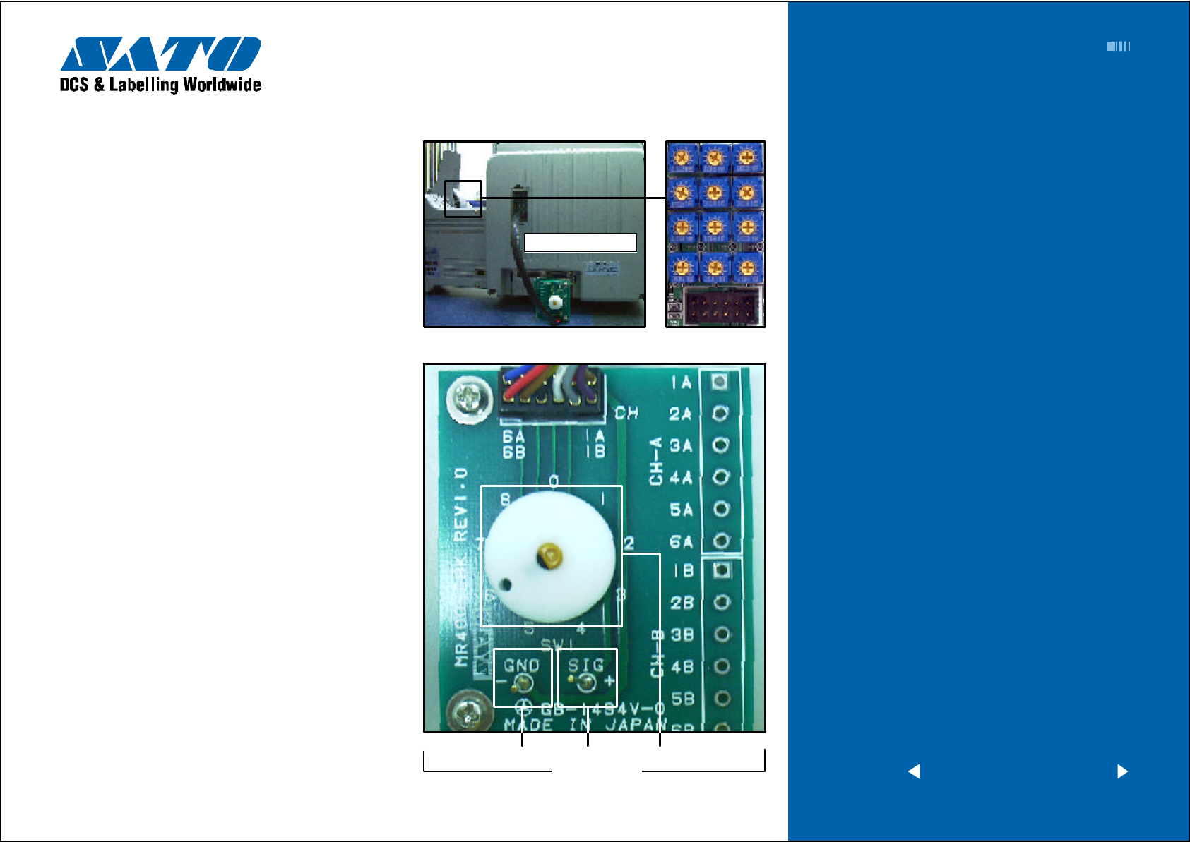
1 Attach the connector from the TP T est Module to the
test port on the MAIN PCB. Note correct positioning
of connector. Nibs on the connector are placed down
on the PCB in the forward position.
2 Attach the ground probe of the Digital Multimeter to
the TP T est Module ground pin (GND PIN).
3 Attach positive probe of the Multimeter to the +SIG
PIN on the TP Test Module terminal.
4 Turn printer power on and rotate the dial to a dial
POS on the TP T est Module. Record the values from
the Multimeter.
5 Confirm voltages are corre ct. If not, then replace
parts or adjustment sensor level. Refer to Check and
Adjustm ent chart.
6 Afte r performing test, pu t the VR cover back to
the printer.
Cable to PCB
Ground PIN
SIG PIN Dial
TP Test Module
< previous | home | next >
Barcode SATO International Pte Ltd
Page 3
EZ Manual: XL4xxe
3
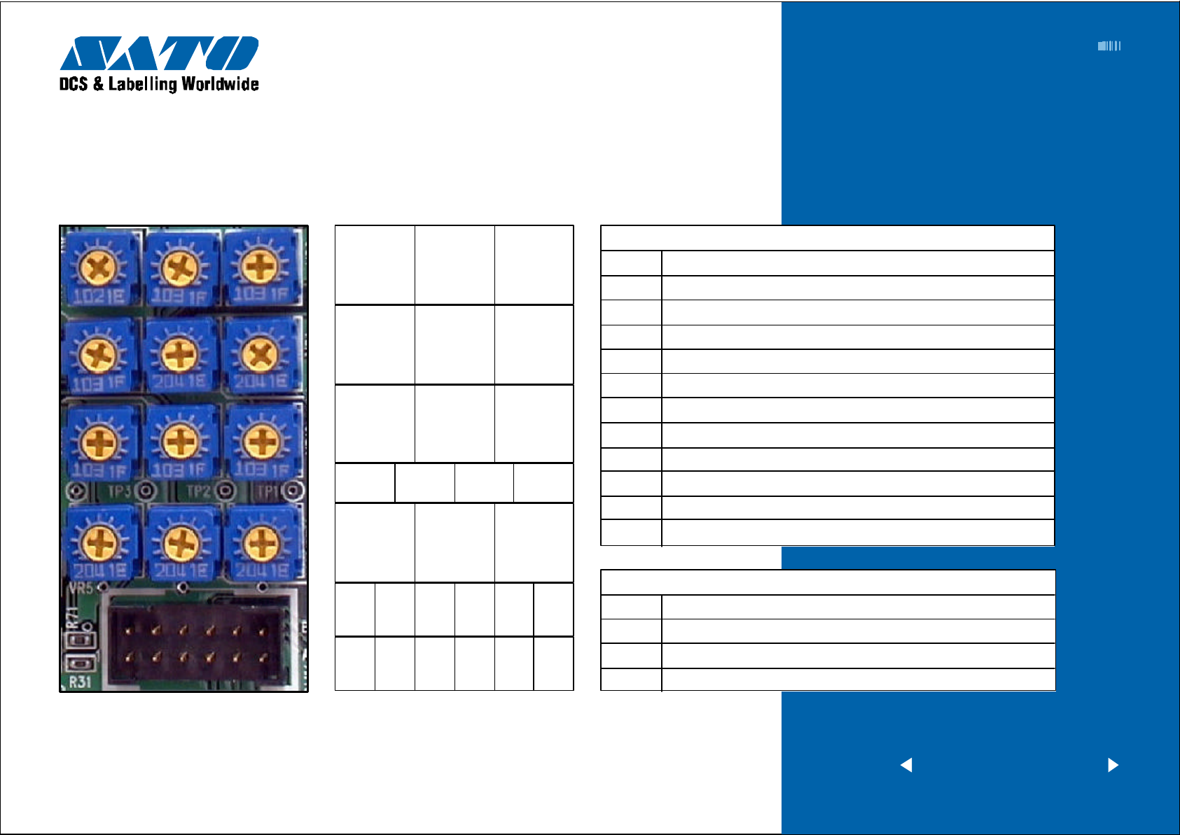
Potentiometers are located on MAIN PCB.
VR3 VR8 VR9
VR4 VR2 VR1
VR11 VR10 VR12
TP4 TP3 TP2 TP1
VR5 VR6 VR7
Electric Checks and Adjustments
Chart 1
VR (Adjustment Level) on Main PCB
VR1 T ag Center Hole And Label Gap Sensor Level Adjustment
VR2 I-Mark Sensor Level Fine Adjustment
VR3 Ribbon Sensor Level Adjustment
VR4 Print Position Adjustment (Use Factory)
VR5 Side Hole Sensor Level Adjustment
VR6 R Corner Hole Sensor Level
VR7 Jump Hole Sensor Level Adjustment
VR8 I-Mark Sensor Level Adjustment
VR9 T ag Center Hole And Label Gap Sensor Level Fine Adjustment
VR10 R Corner Threshold Level Adjustment
VR11 Jump Hole Sensor Threshold Level Adjustment
VR12 Side Hole Sensor Threshold Level Adjustment
B6 B5 B4 B3 B2 B1
A6 A5 A4 A3 A2 A1
Connector PIN No.
TP (check level) on main PCB
TP1 Side Hole Sensor Threshold Level Adjustment
TP2 R Corner Threshold Level Adjustment
TP3 Jump Hole Sensor Threshold Level
TP4 GND
< previous | home | next >
Barcode SATO International Pte Ltd
Page 4
EZ Manual: XL4xxe 4
Electric Checks and Adjustments
Chart 2
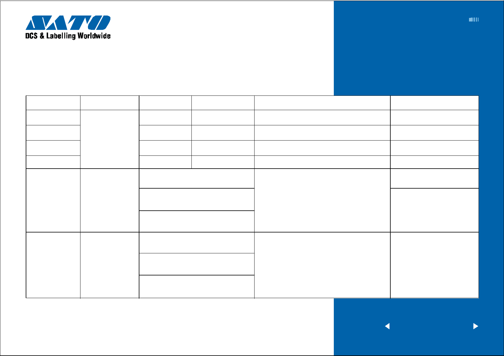
TP TEST POINT CHART
Dial test point Comment Voltage Voltage Range Check pin on TP Test Module and Main PCB Adjustment to VR
0 +5.0 VDC +4.8V to +5.2V CH3A(+5.0V) - CH1A(GND) N/A
1
DC power Supply
2 +3.3 VDC +3.1V to +3.5V CH5A(+3.3V) - CH1A(GND) N/A
3 +24.0 VDC +23.5V to +24.5V CH6A(+24.0V) - CH1A(GND) N/A
4 I-Mark Sensor Level CH1B(+8.4V) - CH1A(GND)
5 CH2B - CH1A(GND) VR1 and VR9 (Fine adjustment)
Gap/T ag Center
Hole Sensor Level
+2.0 VDC +1.9V to +2.1V CH4A(+2.0V) - CH1A(GND) N/A
Low level (Set the no eye-mark point
in the sensor’s) = Less than +0.5V
High level (Set the eye-mark in the sensor’s)
= Low level plus more than +0.9V
High level (with eye-mark point) - Low level
(without eye-mark point) = +0.9V
Low level (S et the label backing liner or centre
hole tag in the sensor’s)
High level (Set the label and tag in the
sensor’s) = Low level plus more than +0.1V
High level (printing point) -
Low level (gap point) = +1.0V
= Less than +0.5V
(VR2 is used for adjusting the
light reception flow. If there is
difference between the high and
low level, adjust VR2 to allow
some level difference.)
VR8 and VR2
< previous | home | next >
Barcode SATO International Pte Ltd
Page 5

EZ Manual: XL4xxe 5
Electric Checks and Adjustments
Chart 3 continued
TP TEST POINT CHART
Dial test point Comment Voltage Voltage Range Check pin on TP Test Module and Main PCB Adjustment to VR
Low level (Set the ribbon without
slit point) : Less than +0.5V
6 Ribbon sensor CH3B - CH1A(GND) VR3
level adjustment
7 Side hole CH4B - CH1A(GND) VR5
sensor level
High level (with slit point) - Low level
(without slit point) +2.0V
Low level (Set the side hole in
the sensor’s) : Less than +0.5V
High level (Set the tag in the
sensor’s) : Low level plus more than +0.2V
High level (printing point) - Low level
(side hole point) : +2.0V
N/A Side hole slice level
Middle of level between high
and low levels
TP1 - TP4(GND) VR12
< previous | home | next >
Barcode SATO International Pte Ltd
Page 6

EZ Manual: XL4xxe 6
Electric Checks and Adjustments
Chart 4 continued
TP TEST POINT CHART
Dial test point Comment Voltage Voltage Range Check pin on TP Test Module and Main PCB Adjustment to VR
Low level (Set the R corner in the sensor’s)
: Less than +0.5V
8 R corner hole CH5B - CH1A(GND) VR6
sensor level
High level (Set the tag in the sensor’s)
: Low level plusmore than +2.0V
(High level on printing point) - (Low level
on R corner point) > +2.0V
N/A R corner TP2 - TP4(GND) VR10
slice level
N/A Jump hole CH6B - CH1A(GND) VR7
sensor level
N/A Jump hole TP3 - TP4(GND) VR11
slice level
Middle of level between high
and low levels
Low level (Set the jumphole in the sensor’s)
: Less than +0.5V and more than +0.2V
High level (Set the tag in the sensor’s)
: Low level plus more than +2.0V
High level (printing point) - Low level
(R corner point) +2.0V
Middle of level between high
and low levels
< previous | home | next >
Barcode SATO International Pte Ltd
Page 7

EZ Manual: XL4xxe 7
Potentiometers are located on FRONT P ANEL
Adjustment VR Function
VR1 Print (Print darkness)
VR2 Cut Position
VR3 Print Position
VR4 Display (LCD Darkness)
Electric Checks and Adjustments
Chart 5
< previous | home | next >
Barcode SATO International Pte Ltd
Page 8

EZ Manual: XL4xxe 8
Cut sensor type VR & Check PIN & Sensor Selector Switch
VR 1
Center-Hole (+) HO (–) SG
Other T ag Position (Right side)
VR 2
I-Mark (+) IM (–) SG
Other T ag position (Right side)
VR 3
R-Corner (+) HO (–) SG
R-Corner Tag position (left side)
SW : If you use R-Corner tag, you must
Cutter Sensor
Adjustment
be set SW.
VR3 R-CornerVR2 I-Mark
VR1 Center -Hole
Other T ags R-Co rner Tags
< previous | home | next >
Barcode SATO International Pte Ltd
Page 9

EZ Manual: XL4xxe 9
Cut sensor type Sensor Level Voltage
High level (Position a TAG in the : M ore than (+) 6.0Volts to less than
sensor’s field of view.) (+) 7.0Volts
Center Hole
Low level (Position a Center Hole : Less than (+) 0.5Volts
in the sensor’s field of view.)
High level (Position a I-Mark in the : M ore than (+) 6.0Volts to less than
sensor’s field of view.) (+) 7.0 volts
I-Mark
Low level (Position a NON I-Mark : Less than (+) 0.5Volts
in the sensor’s field of view.)
High level (Position a TAG in the : M ore than (+) 6.0Volts to less than
sensor’s field of view.) (+) 7.0Volts
R-Corner
Low level (Position a R-Corner in the : Less than (+) 0.5Volts
sensor’s field of view.)
Cutter Sensor
Adjustment continued
G ND
I-Mark
Center-Hole
< previous | home | next >
Barcode SATO International Pte Ltd
Page 10

EZ Manual: XL4xxe
10
Excessive ribbon unwind and rewind tension will result in
variable motion and could be the cause of print quality
problems. Ensure the ribbon rewind and unwind tensions
are within specifications or adjustment of either clutch is
necessary.
STEPS
1 Switch the printer OFF and disconnect the power
cable.
2 O pen the top and front access door. Remove the
ribbon and label stock if installed.
3 Att ach string to an empty ribbon core and place
on the Ribbon Spindle. W ind the string tightly around
the ribbon core in single layer and in clockwise direction.
Attach the end of the string to the tension guage.
4 Gradually lift the tension gauge, pull the string and
unwind it from the core. Once the spindle starts to
move, the gauge should indicate 500 to 700 grams of
tension for ribbon rewind, and 400 and 500 grams of
tension for ribbon unwind. Refer to picture in next page.
Required equipment
1 Empty Ribbon Core and String
2 12mm Wrench
3 2kg T ension Gauge
4 “+” Screwdriver (JIS No.2 equivalent)
3
2
1
Ribbon Clutch
Adjustment
4
5 To adjust the clutch, loosen the locking screw and
m ove the adjust nut CW for more tension and CCW
for less tension. Tighten the locking screw and repeat
steps 3 and 4 until the correct tension is achieved.
< previous | home | next >
Barcode SATO International Pte Ltd
Page 11

EZ Manual: XL4xxe
11
500g - 700g
Rewind
400g - 500g
Unwind
Ribbon Clutch
Adjustment continued
Locking Screw is Inside Adjust Nut
Adjust Nut
< previous | home | next >
Barcode SATO International Pte Ltd
Page 12

Major Adjustment
Adjust screw
EZ Manual: XL4xxe
Print Balance
12
Required equipment
“+” Screwdriver (JIS No.2 equivalent)
T o adjust the print head presser and to ensure consistent
print quality across labels, perform the following steps:
STEP
1 Loosen the set screw.
2 Turn the adjust screw to adjust.
3 If the print is dark at front side, turn the adjust screw
to clockwise.
4 If the print is dark at basic frame side, turn the adjust
screw to anticlockwise.
Adjustment
Graduation Set Screw
5 Finish adjust, then fix the set screw.
< previous | home | next >
Barcode SATO International Pte Ltd
Page 13

Major Adjustment
EZ Manual: XL4xxe
Print Head Position
13
Required equipment
“+” Screwdriver (JIS No.2 equivalent)
“–” Screwdriver
STEP
1 Loosen the two set screws on the adjustment plate.
2 Turn the head mounting screw.
3 Adjust the head position by moving the head adjustment
plate back or forth using t he “–” sc rewdriver.
4 After the adjustment, tighten the set screws and the
head mounting screw.
Adjustment
Adjust Screw
Set Screw
< previous | home | next >
Barcode SATO International Pte Ltd
 Loading...