

®
XL Series
Thermal Transfer Tag Printers
Operator and Technical
Reference Manual for
XL400 and XL410
PN9001038Rev.D

SATO America, Inc.
10350-A Nations Ford Rd.
Charlotte, NC 28273
MainPhone:(704) 644-1650
Technical SupportHotline:(704) 644-1660
Fax:(704) 644-1661
© Copyright 1994, 1995, 1996, 1997
SATO America, Inc.
Warning: This equipment complies with the requirements in Part 15 of
FCC rules for a Class A computing device. Operation of this equipment in a
residential area may cause unacceptable interference to radio and TV
reception requiring the operator to take whatever steps are necessary to
correct the interference.
All rights reserved. No part of this document may be reproduced or issued
to third parties in any form whatsoever without the express permission of
SATO America, Inc. The materials in this document is provided for general
information and is subject to change without notice. SATO America, Inc.
assumes no responibilities for any errors that may appear.
SATOXLSeriesPrinters9001038Rev.D

PREFACE
XL SERIES PRINTER OPERATOR’S MANUAL
The XL Series Printer Operator’s Manual contains basic information about the printer
such as setup, installation, cleaning and maintenance. It also contains complete
instructions on how to use the operator panel to configure the printer. The following
is a brief description of each section in this manual.
SECTION 1. PRINTER OVERVIEW
This section contains a discussion of the printer specifications and optional
features.
SECTION 2. INSTALLATION
This section contains instructions on how to unpack and set up the printer.
SECTION 3. CONFIGURATION
This section contains information on loading the labels and ribbon and how to
use the operator panel to configure the printer.
SECTION 4. CLEANING AND MAINTENANCE
This section contains instructions on how to clean and maintain the printer.
SECTION 5. PROGRAMMING
This section introduces the SATO printer programming language. It contains
the commands that are used with the printer to produce labels with bar codes,
alphanumeric data and graphics.
SECTION 6. INTERFACE SPECIFICATIONS
This section contains the printer’s interface specifications, which include
detailed information on how to properly interface your printer to the host
system.
SECTION 7. TROUBLESHOOTING
This section contains troubleshooting procedures to follow in the event you
have printer problems.
SATOXLSeriesPrinters9001038Rev.DPage-i

Preface
APPENDICES
APPENDIX A: Command Code Quick Reference
APPENDIX B: Bar Code Specifications
APPENDIX C: Custom Characters and Graphics
APPENDIX D: Optional Features
APPENDIX E: Custom Protocol Command Codes
Appendix F: Care Symbol Fonts
Page-ii9001038Rev.DSATOXLSeriesPrinters

TABLE OF CONTENTS
SECTION 1. PRINTER OVERVIEW
Introduction . . . . . . . . . . . . . . . . . . . . . . . . . . . . . 1-1
General Printer Specifications . . . . . . . . . . . . . . . . . . . . 1-2
Character Fonts . . . . . . . . . . . . . . . . . . . . . . . . . . . . 1-4
Bar Codes . . . . . . . . . . . . . . . . . . . . . . . . . . . . . . . 1-5
Physical . . . . . . . . . . . . . . . . . . . . . . . . . . . . . . . . 1-6
Optional Accessories . . . . . . . . . . . . . . . . . . . . . . . . . 1-7
SECTION 2. INSTALLATION
Introduction . . . . . . . . . . . . . . . . . . . . . . . . . . . . . 2-1
Unpacking and Parts Identification . . . . . . . . . . . . . . . . . . 2-2
Setting Up the Printer . . . . . . . . . . . . . . . . . . . . . . . . 2-3
Printer Components . . . . . . . . . . . . . . . . . . . . . . . . . 2-4
Operator Panel . . . . . . . . . . . . . . . . . . . . . . . . . . . . 2-6
Media . . . . . . . . . . . . . . . . . . . . . . . . . . . . . . . . 2-8
Loading Tags and Labels . . . . . . . . . . . . . . . . . . . . . . . 2-12
Loading Ribbon . . . . . . . . . . . . . . . . . . . . . . . . . . . . 2-15
Cut Sensor Adjustment . . . . . . . . . . . . . . . . . . . . . . . . 2-18
Powering On/Off . . . . . . . . . . . . . . . . . . . . . . . . . . . 2-21
Preface
SECTION 3. CONFIGURATION
Introduction . . . . . . . . . . . . . . . . . . . . . . . . . . . . . 3-1
Printer DIP Switch Configuration . . . . . . . . . . . . . . . . . . . 3-2
Printer Adjustments . . . . . . . . . . . . . . . . . . . . . . . . . . 3-6
Normal Mode . . . . . . . . . . . . . . . . . . . . . . . . . . . 3-6
User Mode . . . . . . . . . . . . . . . . . . . . . . . . . . . . 3-8
Service Mode . . . . . . . . . . . . . . . . . . . . . . . . . . . 3-11
User Test Print . . . . . . . . . . . . . . . . . . . . . . . . . . 3-17
Service Test Print . . . . . . . . . . . . . . . . . . . . . . . . . 3-18
Potentiometer Adjustments . . . . . . . . . . . . . . . . . . . . . . 3-19
SECTION 4. CLEANING AND MAINTENANCE
Introduction . . . . . . . . . . . . . . . . . . . . . . . . . . . . . 4-1
Procedures . . . . . . . . . . . . . . . . . . . . . . . . . . . . . . 4-1
SATOXLSeriesPrinters9001038Rev.DPage-iii

Preface
Adjusting the Print Quality . . . . . . . . . . . . . . . . . . . . 4-1
Darkness . . . . . . . . . . . . . . . . . . . . . . . . . . . 4-1
Print Speed . . . . . . . . . . . . . . . . . . . . . . . . . . 4-2
Cleaning the Print Head, Platen, Rollers and Sensors . . . . . . . 4-3
SECTION 5. PROGRAMMING
Introduction . . . . . . . . . . . . . . . . . . . . . . . . . . . . . 5-1
The SATO XL Programming Language . . . . . . . . . . . . . . . . 5-1
Selecting Protocol Control Codes . . . . . . . . . . . . . . . . . . . 5-2
Using Basic . . . . . . . . . . . . . . . . . . . . . . . . . . . . . . 5-2
The Print Area . . . . . . . . . . . . . . . . . . . . . . . . . . . . 5-4
Rotated Fields . . . . . . . . . . . . . . . . . . . . . . . . . . . . 5-8
Command Default Settings . . . . . . . . . . . . . . . . . . . . . . 5-9
Command Codes . . . . . . . . . . . . . . . . . . . . . . . . . . . 5-10
Bar Codes . . . . . . . . . . . . . . . . . . . . . . . . . . . . . 5-11
Bar Codes, Expansion . . . . . . . . . . . . . . . . . . . . . . . 5-13
Bar Codes, Variable Ratio . . . . . . . . . . . . . . . . . . . . . 5-14
Batch Separator . . . . . . . . . . . . . . . . . . . . . . . . . . 5-16
Base Reference Point . . . . . . . . . . . . . . . . . . . . . . . 5-17
Characters, Custom Designed . . . . . . . . . . . . . . . . . . . 5-19
Character Expansion . . . . . . . . . . . . . . . . . . . . . . . 5-21
Character Pitch . . . . . . . . . . . . . . . . . . . . . . . . . . 5-23
Clear Print Job(s) and Memory . . . . . . . . . . . . . . . . . . 5-25
Copy Image Area . . . . . . . . . . . . . . . . . . . . . . . . . 5-26
Fonts OA, OB, XU, XS and XM . . . . . . . . . . . . . . . . . . 5-28
Font, Vector . . . . . . . . . . . . . . . . . . . . . . . . . . . 5-30
Fonts, XB and XL . . . . . . . . . . . . . . . . . . . . . . . . . 5-32
Fonts, XCS and XCL Care Symbol . . . . . . . . . . . . . . . . . 5-34
Form Feed . . . . . . . . . . . . . . . . . . . . . . . . . . . . 5-35
Form Overlay Recall . . . . . . . . . . . . . . . . . . . . . . . 5-36
Form Overlay Store . . . . . . . . . . . . . . . . . . . . . . . . 5-37
Graphics, Custom . . . . . . . . . . . . . . . . . . . . . . . . . 5-38
Graphics, PCX . . . . . . . . . . . . . . . . . . . . . . . . . . 5-40
Job ID Store . . . . . . . . . . . . . . . . . . . . . . . . . . . 5-41
Lines and Boxes . . . . . . . . . . . . . . . . . . . . . . . . . . 5-42
Line Feed . . . . . . . . . . . . . . . . . . . . . . . . . . . . . 5-44
Media Size . . . . . . . . . . . . . . . . . . . . . . . . . . . . 5-46
Off-Line/Pause . . . . . . . . . . . . . . . . . . . . . . . . . . 5-47
Print & Cut Offset . . . . . . . . . . . . . . . . . . . . . . . . . 5-48
Print Darkness . . . . . . . . . . . . . . . . . . . . . . . . . . 5-49
Print Position . . . . . . . . . . . . . . . . . . . . . . . . . . . 5-50
Print Quantity . . . . . . . . . . . . . . . . . . . . . . . . . . 5-52
Print Speed . . . . . . . . . . . . . . . . . . . . . . . . . . . . 5-53
Repeat Label . . . . . . . . . . . . . . . . . . . . . . . . . . . 5-54
Replace Data (Partial Edit) . . . . . . . . . . . . . . . . . . . . 5-55
Reverse Image . . . . . . . . . . . . . . . . . . . . . . . . . . 5-57
Rotate, Fixed Base Reference Point . . . . . . . . . . . . . . . . 5-59
Sequential Numbering . . . . . . . . . . . . . . . . . . . . . . 5-61
Start/Stop Label . . . . . . . . . . . . . . . . . . . . . . . . . 5-63
Page-iv9001038Rev.DSATOXLSeriesPrinters

Preface
Tag Feed . . . . . . . . . . . . . . . . . . . . . . . . . . . . . 5-64
Calendar Option Commands . . . . . . . . . . . . . . . . . . . 5-65
Calendar Increment . . . . . . . . . . . . . . . . . . . . . . 5-66
Calendar Print . . . . . . . . . . . . . . . . . . . . . . . . 5-68
Calendar Set . . . . . . . . . . . . . . . . . . . . . . . . . 5-70
Memory Card Option Commands . . . . . . . . . . . . . . . . . 5-71
Clear Card Memory . . . . . . . . . . . . . . . . . . . . . . 5-72
Expand Memory Area . . . . . . . . . . . . . . . . . . . . . 5-73
Fonts, TrueType Recall . . . . . . . . . . . . . . . . . . . . 5-75
Fonts, TrueType Store . . . . . . . . . . . . . . . . . . . . 5-76
Format/Field Recall . . . . . . . . . . . . . . . . . . . . . . 5-77
Format/Field Store . . . . . . . . . . . . . . . . . . . . . . 5-78
Graphics, Custom Recall . . . . . . . . . . . . . . . . . . . 5-79
Graphics, Custom Store . . . . . . . . . . . . . . . . . . . . 5-80
Graphics, PCX Recall . . . . . . . . . . . . . . . . . . . . . 5-82
Graphics, PCX Store . . . . . . . . . . . . . . . . . . . . . . 5-83
Initialize . . . . . . . . . . . . . . . . . . . . . . . . . . . 5-84
Slot Select . . . . . . . . . . . . . . . . . . . . . . . . . . 5-85
Status . . . . . . . . . . . . . . . . . . . . . . . . . . . . . 5-86
Custom Protocol Codes Download . . . . . . . . . . . . . . . . 5-87
Two-Dimensional Symbols . . . . . . . . . . . . . . . . . . . . 5-89
Data Matrix, Data Format . . . . . . . . . . . . . . . . . . . 5-90
Data Matrix, Data Print . . . . . . . . . . . . . . . . . . . . 5-92
Data Matrix Sequential Numbering . . . . . . . . . . . . . . 5-93
Maxicode . . . . . . . . . . . . . . . . . . . . . . . . . . . 5-95
PDF417 . . . . . . . . . . . . . . . . . . . . . . . . . . . . 5-97
SECTION 6. INTERFACE SPECIFICATIONS
Introduction . . . . . . . . . . . . . . . . . . . . . . . . . . . . . 6-1
Interface Types . . . . . . . . . . . . . . . . . . . . . . . . . . . . 6-1
The Receive Buffer . . . . . . . . . . . . . . . . . . . . . . . . . . 6-2
RS232C Serial Interface . . . . . . . . . . . . . . . . . . . . . . . 6-3
General Specifications . . . . . . . . . . . . . . . . . . . . . . 6-3
Electrical Specifications . . . . . . . . . . . . . . . . . . . . . . 6-3
Pin Assignments . . . . . . . . . . . . . . . . . . . . . . . . . 6-4
Ready/Busy Flow Control . . . . . . . . . . . . . . . . . . . . . 6-4
X-On/X-Off Flow Control . . . . . . . . . . . . . . . . . . . . . 6-5
Bi-Directional Communications . . . . . . . . . . . . . . . . . . 6-6
Centronics Parallel Interface . . . . . . . . . . . . . . . . . . . . . 6-9
Electrical Specifications . . . . . . . . . . . . . . . . . . . . . . 6-9
Accessory (EXT) Connector . . . . . . . . . . . . . . . . . . . . . . 6-10
Pin Assignments . . . . . . . . . . . . . . . . . . . . . . . . . 6-10
SATOXLSeriesPrinters9001038Rev.DPage-v

Preface
SECTION 6. TROUBLESHOOTING
Initial Checklist . . . . . . . . . . . . . . . . . . . . . . . . . . . . 7-1
Using the Centronics (Parallel) Interface . . . . . . . . . . . . . . . 7-1
Using the RS232C (Serial) Interface . . . . . . . . . . . . . . . . . 7-3
Error Signals . . . . . . . . . . . . . . . . . . . . . . . . . . . . . 7-4
APPENDICES
APPENDIX A: Command Code Quick Reference
APPENDIX B: Bar Code Specifications
Bar Code Symbologies . . . . . . . . . . . . . . . . . . . . . . B-1
Codabar . . . . . . . . . . . . . . . . . . . . . . . . . . . . B-2
Code 39 . . . . . . . . . . . . . . . . . . . . . . . . . . . . B-3
Interleaved Two of Five (I 2/5) . . . . . . . . . . . . . . . . B-4
UPC-A/EAN-13 . . . . . . . . . . . . . . . . . . . . . . . . B-5
EAN-8 . . . . . . . . . . . . . . . . . . . . . . . . . . . . . B-8
Code 128 . . . . . . . . . . . . . . . . . . . . . . . . . . . B-7
UPC-E . . . . . . . . . . . . . . . . . . . . . . . . . . . . . B-9
Bookland (UPC/EAN Supplements) . . . . . . . . . . . . . B-10
UCC-128 . . . . . . . . . . . . . . . . . . . . . . . . . . . B-11
Data Matrix . . . . . . . . . . . . . . . . . . . . . . . . . . B-13
Maxicode . . . . . . . . . . . . . . . . . . . . . . . . . . . B-15
PDF417 . . . . . . . . . . . . . . . . . . . . . . . . . . . . B-16
Code 128 Character Table . . . . . . . . . . . . . . . . . . B-17
APPENDIX C: Custom Characters and Graphics
Custom Designed Characters Example . . . . . . . . . . . . . . C-1
Custom Graphics Example . . . . . . . . . . . . . . . . . . . . C-4
PCX Graphics Example . . . . . . . . . . . . . . . . . . . . . . C-8
APPENDIX D: Optional Accessories
Label Rewinder . . . . . . . . . . . . . . . . . . . . . . . . . . D-1
PCMCIA Memory Cards . . . . . . . . . . . . . . . . . . . . . . D-2
Stacker . . . . . . . . . . . . . . . . . . . . . . . . . . . . . . D-4
Calendar . . . . . . . . . . . . . . . . . . . . . . . . . . . . . D-6
APPENDIX E: Custom Protocol Command Codes
Description . . . . . . . . . . . . . . . . . . . . . . . . . . . . E-1
Download Command Structure . . . . . . . . . . . . . . . . . . E-1
Download Procedure . . . . . . . . . . . . . . . . . . . . . . . E-2
Reset . . . . . . . . . . . . . . . . . . . . . . . . . . . . . . . E-2
Appendix F: Care Symbol Fonts
XCS Font . . . . . . . . . . . . . . . . . . . . . . . . . . . . . F-1
XCM Font . . . . . . . . . . . . . . . . . . . . . . . . . . . . . F-2
Page-vi9001038Rev.DSATOXLSeriesPrinters

INTRODUCTION
The SATO XL400 and XL410 Thermal Transfer Printers are complete,
high-performance labeling systems designed specifically for printing tags and labels.
All printer parameters are programmable using the front panel controls and DIP
switches. All popular bar codes, including 2-D codes, eight human-readable fonts
with two Care Symbol fonts and a fast and efficient vector font, are resident in
memory, providing literally thousands of type styles and sizes.
The Operator’s Manual will help you understand the basic operations of the printer,
such as setup, installation, configuration, cleaning and maintenance.
The major difference in the XL400 and the XL410 is the resolution of the head. The
XL400 with its 203 dpi head provides an economical labeling solution for most
applications. The XL410 provides a higher print resolution, 305 dpi, to give
laser-quality printing. It is useful when high-resolution printing is required, such as
when printing detailed graphic images. Both printers can print labels up to 4.0 inches
wide and 9.4 inches long using internal memory. If longer labels are required, a
PCMCIA memory card option is available, allowing 203 dpi labels up to 49.2 inches
(32.8 inches for 305 dpi).
SECTION 1.
PRINTER OVERVIEW
All of the XL printers use the same command codes. The only differences are the
allowable values representing print positions on the label. These values are specified
in “dots” and will vary depending upon the resolution of the printer and the amount
of memory available for imaging the label. The allowable range for each printer is
specified in a table for those commands.
The standard configuration for the XL printers includes an integrated Cutter which
can operate at the maximum print speed. A Stacker is available as an option and can
stack up to 500 labels up to 3.9 inches wide and 5.9 inches long at maximum print
speeds.
The following general information is presented in this section:
• General Printer Specifications
• Optional Accessories
SATOXL SeriesPrinters9001038 Rev. DPage 1-1
Section 1. Printer Overview
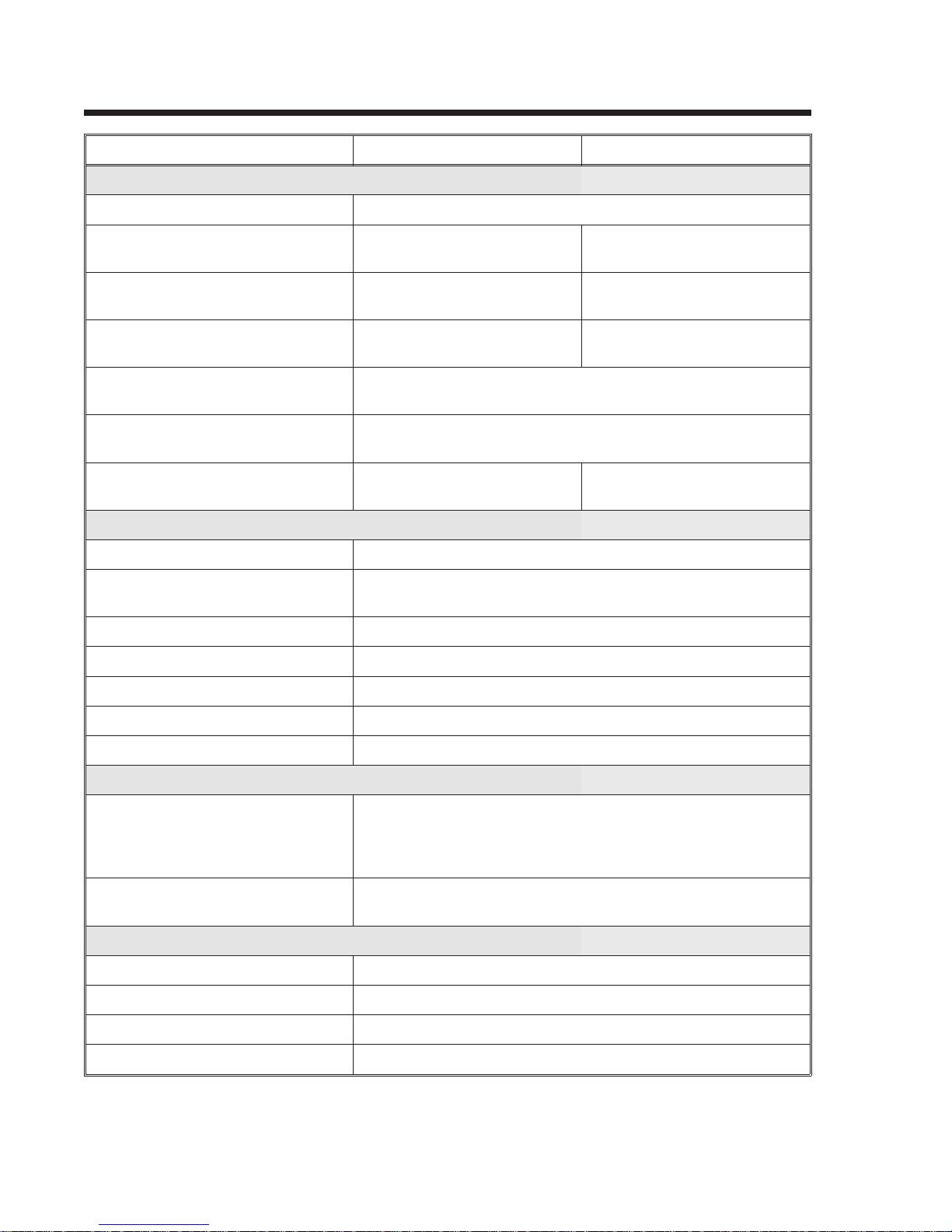
GENERAL PRINTER SPECIFICATIONS
SPECIFICATION XL400 XL410
PRINT
Method Direct or Thermal Transfer
Speed (User Selectable) 5 to 8 ips
125 to 200 mm/s
Print Module (Dot Size) .0049 in.
.125 mm
Resolution 203 dpi
8 dpmm
Maximum Print Width 3.94 in.
100 mm
Maximum Print Length 9.45 in.
240 mm
Maximum Print Length
with 2MB Memory Card
MEDIA
Minimum Width 1.26 in. (32 mm)
Minimum Length .75 in. (19 mm) Labels
Maximum Width 4.0 in. (102 mm)
Type Die Cut Labels, Fan-Fold, Tag Stock or Continuous
49.2 in.
1249 mm
1.0 in. (25 mm) Tags
4 to 6 ips
100 to 150 mm/s
.0033 in.
.083 mm
305 dpi
12 dpmm
32.8 in.
833 mm
Caliper (max) .012 in. (.3 mm)
Roll OD (max) 9.8 in. (249 mm)
Core ID (min) 4.0 in. (102 mm)
SENSING
See-Thru
Label Gap/Center Hole Tag
Side Hole Tag
Side Notch (R-Corner Tag)
Reflective Eye-Mark
Eye-Mark Label or Tag
RIBBON
Maximum Width 4.0 in. (102 mm)
Length 1475 ft. (450 M)
Wind Ink-In
Thickness 4.5 micron
0.4 in. (16mm0 to 2.0 in. (50mm)
1.3 in. (34mm) to 3.7 in. (94mm)
Adjustable
0.1 in. (2.5mm)
Fixed
0.28 in. (7 mm)
Page 1- 29001038 Rev. DSATOXL SeriesPrinters

Section 1. Printer Overview
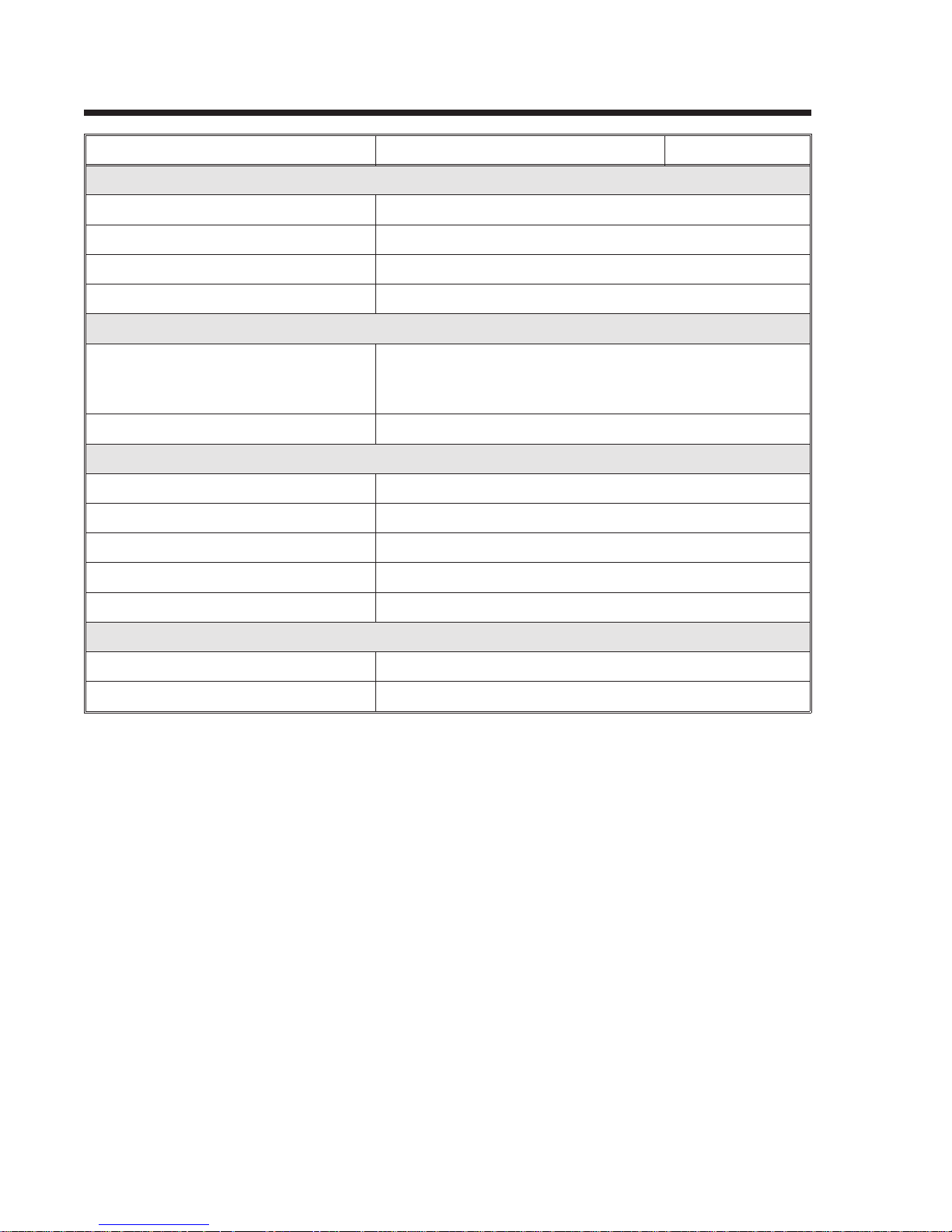
GENERAL PRINTER SPECIFICATIONS (cont’d)
SPECIFICATION XL400 XL410
CONTROLS AND SIGNALS
On-Line LED Green
Cutter Green
Error LED Red
LCD Panel 2 Line x 16 Character
Start/Stop Switch Rear
Feed Switch Front Panel
Cutter Front Panel
Eject Front Panel
Media Front Panel
Configuration 3 x 8 DIP, Inside Cover
Power On/Off Switch Rear Panel
POTENTIOMETER ADJUSTMENTS
Print Darkness Inside Cover
Pitch Inside Cover
Offset Inside Cover
Display Inside Cover
INTERFACE CONNECTIONS
Parallel (AMP 36 pin) Centronics Compatible
Serial (DB25S) RS232C (2400 to 19.2K bps)
Serial Protocol Hardware Flow Control (Ready/Busy)
Software Flow Control (X-On/X-Off)
Bi-directional (ENQ/Response)
Data Transmission ASCII Format
PROCESSING
CPU 32 Bit RISC
ROM 1 MByte
DRAM 2 MByte
SATOXL SeriesPrinters9001038 Rev. DPage 1-3

Section 1. Printer Overview
CHARACTER FONTS
SPECIFICATION XL400 XL410
MATRIX FONTS
XU Font (5 dots W x 9 dots H) Helvetica
XS Font (17 dots W x 17 dots H) Univers Condensed Bold
XM Font (24 dots W x 24 dots H) Univers Condensed Bold
OA Font (15 dots W x 22 dots H)
OCR-A
OB Font 20 dots W x 24 dots H)
OCR-B
XCS (24 dot W x 24 dot H) Care Symbol
XCL (36 dots W x 36 dots H) Care symbol
AUTO SMOOTHING FONTS
XB XB Font (48 dots W x 48 dots H) Univers
Condensed Bold
XL XL Font (48 dot W x 48 dots H) Sans Serif
VECTOR FONT
Proportional or Fixed Spacing
Font Size 50 x 50 dots to 999 x 999 dots
10 Font Variations
DOWNLOADABLE FONTS
TrueType Fonts with Optional Memory Card
CHARACTER CONTROL
Expansion up to 12X in either the X or Y
coordinates
Character Pitch control
Line Space control
Journal Print facility
0°, 90°, 180° and 270° Rotation
(22 dots W x 33 dots H)
OCR A
(30 dots W x 36 dots H)
OCR B
Page 1- 49001038 Rev. DSATOXL SeriesPrinters

Section 1. Printer Overview
Bar Codes
SPECIFICATION XL400 XL410
SYMBOLOGIES
Bookland (UPC/EAN Supplemental)
EAN-8, EAN-13
CODABAR
Code 39
Code 128
Interleaved 2 of 5
UCC/EAN-128
UPC-A and UPC-E
Data Matrix
Maxicode
PDF417
Ratios 1:2, 1:3, 2:5 User definable bar widths
Bar Height 4 to 600 dots, User programmable
Rotation 0°, 90°, 180° and 270°
OTHER FEATURES
Sequential Numbering Sequential numbering of both numerics and bar codes
Custom Characters RAM storage for special characters
Graphics Full dot addressable graphics, SATO Hex/Binary or PCX
formats
Form Overlay Form overlay for high-speed editing of complex formats
SATOXL SeriesPrinters9001038 Rev. DPage 1-5
Section 1. Printer Overview
PHYSICAL
SPECIFICATION XL400 XL410
DIMENSIONS
Wide 19.6 in. (302 mm)
Deep 11.8 in. (552 mm)
High 11.5 in. (294 mm)
WEIGHT 30.8 lbs (14 Kg)
POWER REQUIREMENTS
Voltage
Power Consumption 300 Watts Operating
ENVIRONMENTAL
Operating Temperature 41° to 104°F (5° to 40°C
Storage Temperature -0° to 104°F (-20° to 40°C)
Operating Humidity 15-85 % RH, non-condensing
Storage Humidity Max 90% RH, non-condensing
Electrostatic Discharge 8KV
REGULATORY APPROVALS
Safety UL, CSA, CE
RFI/EMI FCC Class A
100 - 115 V (±10 %)
220V (±10 %)
50/60 Hz (±1%)
Page 1- 69001038 Rev. DSATOXL SeriesPrinters
Section 1. Printer Overview
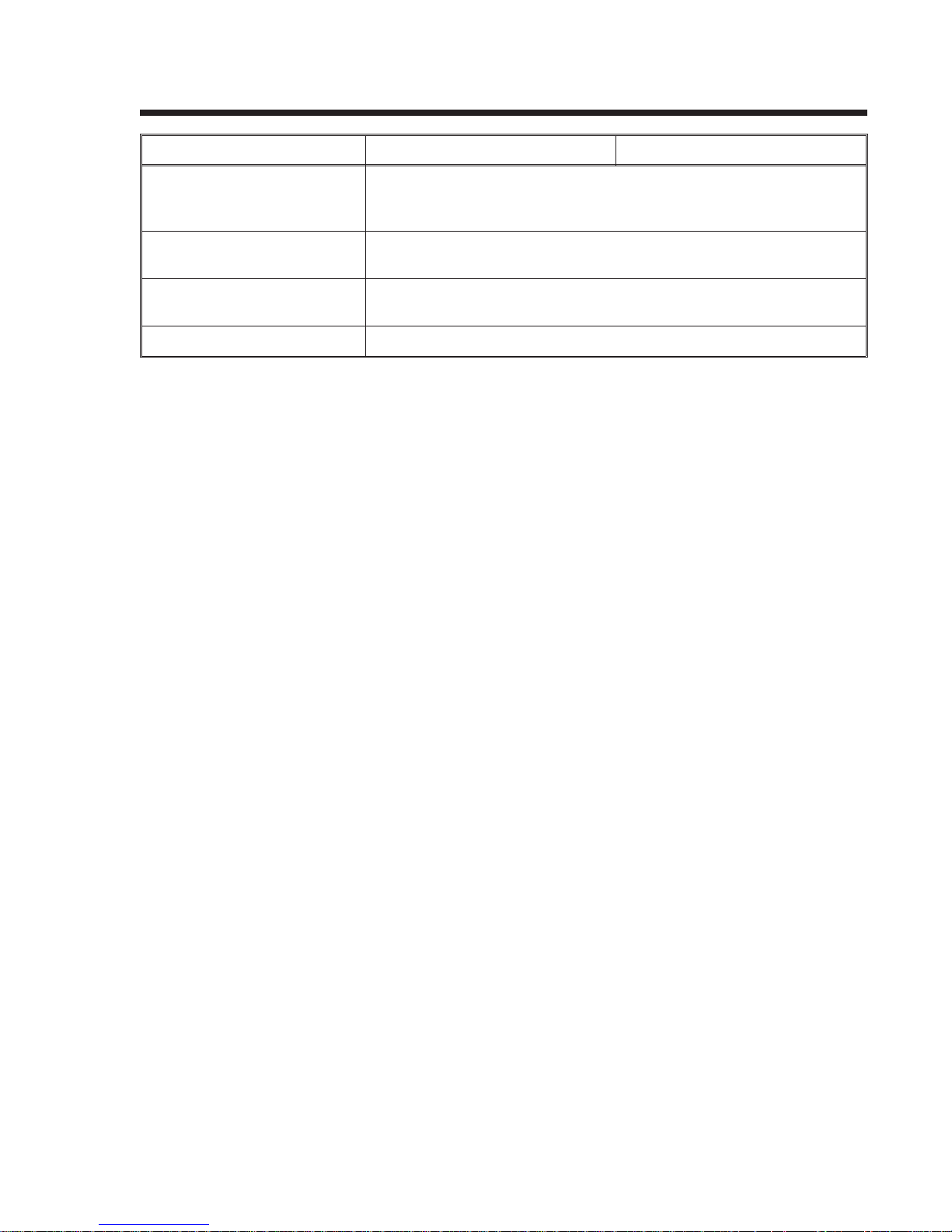
OPTIONAL ACCESSORIES
ACCESSORY XL400 XL412
MEMORY EXPANSION Two slots for PCMCIA Memory Cards (up to 2MB each). Can be used
for graphic file storage, print buffer expansion and downloaded
TrueType fonts.
CALENDAR An internally mounted Date/Time clock that can be used to date/time
stamp labels at the time of printing.
INTEGRATED STACKER Allows cut labels to be stacked. Interfaces to EXT Accessory Port
connector.
LABEL REWINDER External option rewinds labels onto a roll after they are printed.
SATOXL SeriesPrinters9001038 Rev. DPage 1-7

Section 1. Printer Overview
This page left intentionally blank.
Page 1- 89001038 Rev. DSATOXL SeriesPrinters

INTRODUCTION
This section is provided to assist you in taking the XL printer from the shipping
container and familiarization with the controls.
The following information is provided in this section:
SECTION 2.
INSTALLATION
• Unpacking and Parts Identification
• Setting Up the Printer
• Loading Labels or Tags
• Loading the Ribbon
• Adjusting the Sensors
• Powering On/Off
SATOXL SeriesPrinters9001038 Rev. DPage 2-1
Section 2. Installation
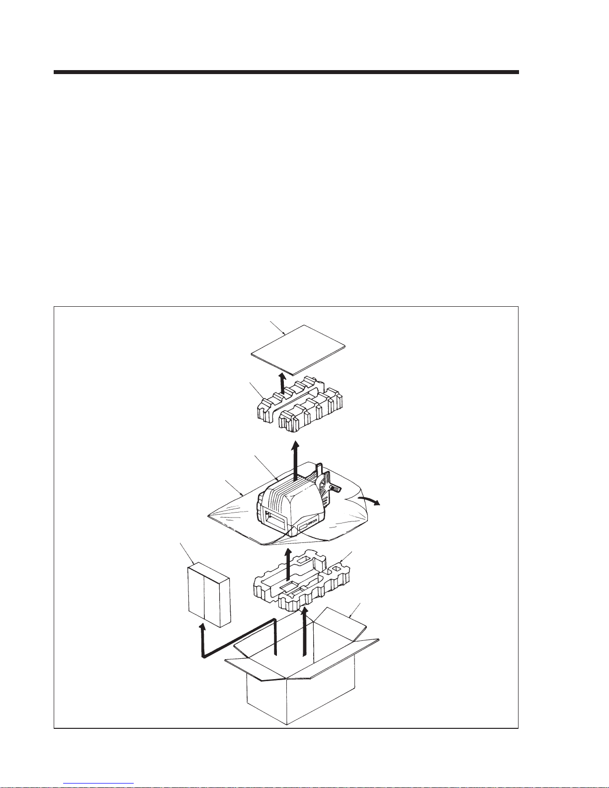
UNPACKING AND PARTS IDENTIFICATION
Consider the following when unpacking the printer:
• The box should stay right-side up.
• Lift the printer out of the box carefully.
• Remove the plastic covering from the printer.
• Remove the accessory items from their protective containers.
• If the printer has been stored in a cold environment, allow it to reach room
temperature before powering it on.
• Set the printer on a solid, flat surface. Inspect the shipping container and
printer for any sign of damage that may have occured during shipping.
Note: The following illustrations are representative only. Your printer may not be packed
exactly as shown, but the unpacking steps are similar.
Plastic Protective
Accessory Box
Cardboard Cover
Top Foam Inserts
XL Printer
Bottom Foam Inserts
Shipping Container
Page 2-29001038 Rev. DSATOXL SeriesPrinters

Verify that you have the following materials when unpackaging:
• Printer
• Power Cord
• Extra Ribbon Core
• Operator’s Manual
SETTING UP THE PRINTER
Consider the following when setting up the printer:
• Locate a solid, flat surface with adequate room to set the printer. If a
Cutter/Stacker is to be used with the printer, make sure thaere is adequate
room for the unit. The printer cover swings upward and back, make sure
there is enough clearance for the cover to swing open.
• The location should be near the host computer or terminal. The maximum
distance for RS232 cables is 50 feet and six feet for Centronics parallel
cables. Cables can be purchased locally and their configuration will depend
upon the host system.
Section 2. Installation
• For information on interfacing the printer to a host system, see Section 6:
Interface Specifications.
The procedures for setting up the printer and adjusting the sensors are outlined in
Section 2. The procedures for setting ut the operating parameters (Print Speed, Pitch
Offset, etc.)are outlined in Section 3.
• Load the ribbon (see page 2-15).
• Load the Media (see page 2-12).
• Setup the printer for the media type (see page 2-8). You must use the LCD
panel to select the proper media type (see page 2-14). The selections are:
Center Hole Tag
I-Mark Tag
Side Hole Tag
R-Corner Tag
Label Gap
I-Mark Label
• Adjust the Cutter Sensor (see page 2-18). Note: The Cutter Sensor must be
set up even if the Cutter is disabled.
• Adjust the Cutter Offset to corectly locate the cut position. This can
generally be done with the Cut Position potentiometer on the Control Panel
(see page 3-20) which has a +/- 3.75mm range. If this is insufficient, the
Cut Offset can be moved +/- 99 dots using the LCD panel (see page 3-15).
• Set the Pitch, Cut and Backfeed Offset using the LCD panel (see page 3-14).
SATOXL SeriesPrinters9001038 Rev. DPage 2-3

Section 2. Installation
PRINTER COMPONENTS
Before attempting to set up the printer, please familiarize yourself with the major
components.
Cover
Print Head
Ribbon Rewind
Cutter
Ribbon Unwind
Media Supply Spindle
Media Retaining Plate
Head Lock Lever
Operator Panel
Page 2-49001038 Rev. DSATOXL SeriesPrinters

DIP Switch and
Potentiometer Cover
Section 2. Installation
Fuse
Media Hold-Down
Power Switch
Power SwitchAC Connector
INTERFACE
CONNECTORS
Centronics Parallel
Serial RS232
EXT Accessory
SATOXL SeriesPrinters9001038 Rev. DPage 2-5

Section 2. Installation
Cutter On/Off LED
OPERATOR PANEL
The XL Operator Panel consists of three LED indicators and five key switches. They
are used to set the printer operating parameters and to indicate the status of the
printer to the operator.
SATO XL PRINTER
LCD Display
On Line LED
Start/Stop
Error LED
Feed
Cutter
On/Off
Eject
Media
Type
On Line: LED. Illuminated when the printer is ready to receive
data.
Cutter On/Off: LED. Illuminated when the Cutter is enabled.
Error: LED. Illuminated when there is a system fault such as
an open print head.
LCD Display: 2 Line x 16 Character LCD display. Used for setting
operational parameters of the printer.
Start/Stop: Toggles the printer On and Off Line.
Feed: Momentary Switch. Feed one tag or label each time it
is pressed. Effective only when printer is Off Line.
Cutter On/Off: Momentary Switch. Enables or disables the cutter.
Effective only when printer is Off Line.
Eject: Momentary Switch. When pressed, feeds out any
printed labels. If the cutter is enabled, it feeds and cuts
the label or tag.
Media Type: Momentary Switch. Steps through the media types.
Page 2-69001038 Rev. DSATOXL SeriesPrinters

Section 2. Installation
Operator Panel
Push in for Tilt
position
The Operator Panel has two positions; one is flush with the printer (vertical) and the
other is tilted backward. The position should be set for the best viewing by the
operator.
Release for Vertical
position
Operator Panel
SATOXL SeriesPrinters9001038 Rev. DPage 2-7

Section 2. Installation
MEDIA
Tag Types
Tag Cut Line
Center-Hole Tag without Notch
(set printer for Center Hole)
Side Notch
Center-Hole Tag with Side Notch
(set printer for Center Hole)
Outside Edge
Side-Hole Tag without Notch
(set printer for Side Hole)
Page 2-89001038 Rev. DSATOXL SeriesPrinters
Outside Edge
Side-Hole Tag with Side Notch
(set printer for Side Hole)

X: = 3.75 mm minimum
Y: = 2 mm minimum, 3 mm maximum
Z: = Center of Notch Width = 2.5mm
R-Corner Specifications
(set printer for R-Corner Tag)
Section 2. Installation
I-Mark
Label Gap
I-Mark Specifications
(set printer for I-Mark Tag or Label)
SATOXL SeriesPrinters9001038 Rev. DPage 2-9

Section 2. Installation
Label Gap
Label Gap Specifications
(set printer for Label Gap)
Media Specifications
MEDIA TYPE MINIMUM SIZE MAXIMUM SIZE
Center Hole Tag 32mm W x 25 mm L 100mm W x 240mm L
I-Mark Tag 32mm W x 25mm L 100mm W x 240mm L
Side Hole Tag 50mm W x 25mm L 100mm W x 240mm L
R-Corner Tag 32mm W x 25mm L 100mm W x 240mm L
Label with Gap 25mm W x 16mm L 100mm W x 237mm L
I-Mark Label 32mm W x 25mm L 100mm W x 237mm L
Page 2-109001038 Rev. DSATOXL SeriesPrinters
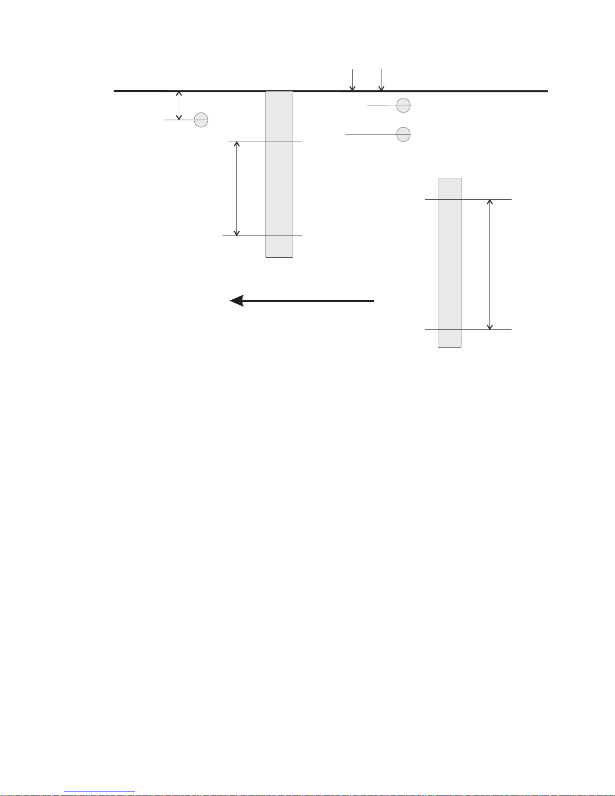
I-Mark Sensor
7mm
Section 2. Installation
INSIDE MEDIA GUIDE
R-Corner Sensor
2.5mm
16mm
Center Hole &
Gap Sensor
Range
50mm
Sensor
(not used)
Feed Direction
Sensor Positions Relative to Inside Media Guide
34mm
Side Hole Tag
Sensor Range
94mm
SATOXL SeriesPrinters9001038 Rev. DPage 2-11

Section 2. Installation
LOADING TAGS AND LABELS
Open the Cover and power the printer on.
Turn power on and open the cover.
Cover
Remove the Media Retaining Plate and
place the media roll on the Media Supply
Spindle. Replace the Media Retaining Plate
to secure the roll in place.
Remove the Media Retaining Plate and load the tag roll.
Note: The media should come off the
bottom of the roll (wound face-in). If
media is used that is wound face-out, the
label curl can cause problems with the
stacking of the labels.
Tag Roll
Media Retaining Plate
Power Switch
Media Supply Spindle
Page 2-129001038 Rev. DSATOXL SeriesPrinters

Section 2. Installation
Open the print head by rotating the Head Release Lever to the rear of the printer. Open
the Media Hold Down by lifting up on the release tab underneath the green tab marked
“PUSH.”
Media Hold Down
Head Lock Lever
Load the tags from the rear until the leading edge of the first tag is underneath the print
head. Loosen the Paper Guide Lock Screw and adjust the position of the Paper Guide
until it holds the tag gently against the inside of the paper path (this also positions the
sensor assembly). Retighten the Paper Guide Lock Screw. See page 2-11 for sensor
locations.
Media Hold Down
Sensor Label
Head Lock Lever
Tag Setting
Position
SATOXL SeriesPrinters9001038 Rev. DPage 2-13
Tag
Paper Guide
Paper Guide Lock Screw

Section 2. Installation
Close the Media Hold Down by pushing down on the green tab marked “PUSH.” It will
Close and latch the Media Hold Down and then close the Cover.
automatically latch in place. Close the print head by rotating the Head Lock Lever toward
the front of the printer until it latches in place.
Cover
Media Hold Down
Power the printer On and press the Start/Stop key. The tags should be ejected if the
Media Type setting is correct (the factory setting is Center-Hole Tag, however the printer
retains the last setting entered via the LCD Panel). If the Media Type setting is incorrect, a
“Sensor Error” will be displayed on the LCD. If this occurs, you must open the print head
and Media Hold Down, reposition the media, close the print head and Media Hold Down
and select the correct media type by pressing the Media Type key (see page 2-8) and
press the Start/Stop key.
Ejected Tags
Start/Stop Key
Note: If you get a “Cutter Error,” you must
Refer to Ribbon Loading in this section if
correctly podsition the Cut Sensor. See
there is no ribbon in the printer.
page 2-19. This can occur even if the
Cutter is disabled.
Page 2-149001038 Rev. DSATOXL SeriesPrinters

LOADING RIBBON
Turn the power off and open the Cover.
Section 2. Installation
Cover
Power Switch
Open the print head by rotating the Head Lock Lever toward the rear of the printer. It
will automatically retract to the open position.
Head Lock
Lever
SATOXL SeriesPrinters9001038 Rev. DPage 2-15

Section 2. Installation
Place the ribbon on the Ribbon Unwind Shaft, making sure the ribbon unwind direction is
as shown). Place an empty ribbon core one the Ribbon Rewind Shaft.
Ribbon Unwind
Ribbon Rewind
Ribbon
Ribbon Core
Route the ribbon as shown and tape the end to the ribbon core on the Ribbon Rewind
Shaft. Rotate the shaft in a clockwise direction until several layers of ribbon are wound
on the core.
Tape
Ribbon
Page 2-169001038 Rev. DSATOXL SeriesPrinters

Section 2. Installation
Make sure the media is fed into the printer with the leading edge underneath the print
head. Close and latch the print head in the down position by rotating the Head Latch.
Cover
Head Lock Lever
Power the printer On. Press the Start/Stop key to initiate the automatic media feed.
If the Media Type setting is incorrect, a “Sensor Error” will be displayed on the LCD.
If this occurs, you must open the print head and Media Hold Down, reposition the
media, close the print head and Media Hold Down and select the correct media type
by pressing the Media Type key (see page 2-8). Press the Start/Stop key.
Start/Stop Key
Note: If you get a “Cutter Error,” you
must correctly position the Cut Sensor.
See page 3-20. This can occur even if
the Cutter is disabled.
SATOXL SeriesPrinters9001038 Rev. DPage 2-17

Section 2. Installation
CUT SENSOR ADJUSTMENT
These adjustments are for R-Corner Tag (Side-Notch), Center-Hole and Edge-Hole
tags only.
Open the cover. The Cut Sensors are located on an adjustable assembly that must be
correctly positioned for the type of media used. They must be adjusted correctly even
though the Cutter is disabled. If they are not, a “Cutter Error” will result when you try to
feed tags.
Cover
Loosen the green Sensor Adjustment Thumbscrew on the Cutter Sensor assembly.
Align the notch on the Cutter Sensor Assembly to the position of the tag registration
mark using the scale.
Sensor
Adjustment
Thumbscrew
Cutter
Sensor
Assembly
Page 2-189001038 Rev. DSATOXL SeriesPrinters

Section 2. Installation
The scale used depends upon the type of media selected (i.e. R-Corner, Center-Hole or
Side-Hole) and the setting corresponds to the width of the media (i.e., if you are using
center hole tags that are 80mm wide, the notch should be set at the 80mm mark of the
black scale).
Notch
R-Corner: . . Inside scale, 32 to 42mm.
Center-Hole: . Black scale
........ Other Tag, 47 to 100mm
Scale
........ R-Corner, 32 to 42mm
Side Hole: . . Blue scale, 50 to 100mm
See Tag Charts on pages 2-8 to 2-9 if you
are unsure about tag type.
If you are using R-Corner Notch Tags, the tag notch must be on the inside edge of the
tag and the position the Sensor Select Switch should be towards the outside of the
printer. For all other tags, the Sensor Selector Switch should be towards the inside of
the printer.
R-Corner Other Tag
See Tag Charts on pages 2-8 to 2-9 if you
are unsure about tag type.
SATOXL SeriesPrinters9001038 Rev. DPage 2-19

Section 2. Installation
After adjusting the Cutter Sensor Assembly, tighten the Sensor Adjustment
Thumbscrew and close the Cover.
Cover
Sensor Adjustment
Thumbscrew
After adjusting the Cutter Sensor, make sure you:
• Have the media and ribbon loaded correctly.
• The media and ribbon type are correct for the configuration.
• The Print Head and Media Hold Down are latched in the closed position.
• The cover is closed.
NOTES:
If the media is not positioned correctly, press the FEED key to realign it.
If power is removed while printing, the media may be incorrectly positioned when power
is restored and the printer may print several blank tags. Press the Start/Stop key to
pause the print job and turn power off. When power is reapplied, the printer will
correctly position the tags.
Page 2-209001038 Rev. DSATOXL SeriesPrinters

POWERING ON/OFF
Section 2. Installation
SATO XL PRINTER
Total number of labels printed. Will increment
each time a label is printed since the last
time the printer was powered On.
Total number of labels to be printed. Will
decrement each time a label is printed.
Before Turning Power Off
When removing power from the printer, you should first feed any printed labels or
tags out of the printer by pressing the EJECT key while the printer is On Line. Any
tags printed but still in the printer will be fed out, cut and the tag/label retracted to
place the first print line under the head.
Note: The EJECT operation can be controlled via software commands from the host.
After the printed labels have been ejected from the printer, place the printer in the
OFF LINE state before removing power. If the label/tag position is not disturbed
while power is off, then the first printable label/tag will be in the correct position
when power is reapplied. The Media Type setting is retained in the printer even
though power is removed. When power is reapplied, the first print line of the
tag/label will be correctly positioned under the print head.
Replenishing the Tag Supply
When replenishing the tag/label supply with the same type and size, it is not
necessary to power the printer off. The printer will automatically position the new
media to the correct position.
• Raise the print head and relatch it to clear the “Paper End” Error.
• Unlatch the Media Hold Down and position the leading edge of the
media even with the mark on the “Tag Setting Position” label. If labels are
SATOXL SeriesPrinters9001038 Rev. DPage 2-21

Section 2. Installation
• Close the Media Hold Down and press the START/STOP key.
• The printer will automatically feed the media into the printer and position
being used, the leading edge of the first label should be under the print
head and even with the “Label Setting Position” label.
it correctly.
Page 2-229001038 Rev. DSATOXL SeriesPrinters

INTRODUCTION
The configuration settings for the XL Series printers are set in two ways. The first is
via three DIP switches (DSW1, DSW2 and DSW3) located under the cover. The other
is using the Operator Panel LCD Display.
SECTION 3.
CONFIGURATION
CONTROL PANEL
Label Hold Down
On Line LED
Control Panel Cover
Cutter On/Off LED
Power Switch
Error LED
Fuse
AC
Connector
SATOXL SeriesPrinters9001038 Rev. DPage 3-1
SATO XL PRINTER
LCD Display
Start/Stop
Feed
Cutter
On/Off
Eject
Media
Type

Section 3. Printer Configuration
PRINTER DIP SWITCH CONFIGURATION
DIP Switch Panels
There are three DIP switches (DSW1, DSW2 and DSW3) located underneath an
access panel inside the printer. These switches can be used to set:
• RS232C transmit/receive parameters
• Thermal transfer or direct thermal mode
• Head check mode
• Hex dump mode
• Receive buffer size
• Operation mode
Each switch is an eight section “toggle” switch. The ON position is always to the top
(up). To set the switches, first power the unit Off, then position the DIP switches.
Finally, after placing the switches in the desired positions, power the printer back on.
The switch settings are read by the printer electronics during the power up sequence.
They will not become effective until the power is cycled.
RS232 Transmit/Receive Setting
Data Bit Selection (DSW1-1) - This switch sets the printer to receive either 7 or 8
bit data bits for each byte transmitted.
DSW1
DSW1-1 SETTING
Off 8 data bits
On 7 data bits
ON
OFF
12345678
Parity Selection (DSW1-2, DSW1-3) - These switches select the type of parity
used for error detection.
DSW1-2 DSW1-3 SETTING
Off Off No Parity
Off On Even
On Off Odd
On On Not Used
ON
OFF
12345678
DSW1
Page 3-29001038 Rev. DSATOXL SeriesPrinters

Section 3. Printer Configuration
Stop Bit Selection (DSW1-4) - Selects the number of stop bits to end each byte
transmission.
DSW1-4 SETTING
Off 1 Stop Bit
On 2 Stop Bits
ON
OFF
12345678
DSW1
Baud Rate Selection (DSW1-5, DSW1-6) - Selects the data rate (bps) for the
RS232 port.
DSW1-5 DSW1-6 SETTING
Off Off 9600
Off On 19200
On Off 4800
On On 2400
ON
OFF
12345678
DSW1
Protocol Selection (DSW1-7, DSW1-8) - Selects the flow control and status
reporting protocols. See Section 6: Interface Specifications for more information.
DSW1-7 DSW1-8 SETTING
Off Off Rdy/Bsy
Off On X-On/X-Off
On Off Bi-Com
On On Not Used
ON
OFF
12345678
DSW1
Printer Set Up
Print Mode Selection (DSW2-1) - Selects between direct thermal printing on
thermally sensitive paper and thermal transfer printing using a ribbon.
DSW2-1 SETTING
Off Therm Xfr
On Direct Therm
ON
OFF
12345678
DSW2
Reserved (DSW2-2) - Reserved for future use
Head Check Selection (DSW2-3) - When selected, the printer will check for head
elements that are electrically malfunctioning.
DSW2
DSW2-3 SETTING
Off Disabled
On Enabled
ON
OFF
12345678
SATOXL SeriesPrinters9001038 Rev. DPage 3-3

Section 3. Printer Configuration
Reserved (DSW2-4) - Reserved for future use.
Receive Buffer Selection(DSW2-5) - Selects the operating mode of the receive
buffer. See Section 6: Interface Specifications for more information.
DSW2-5 SETTING
Off Single Job
On Multi Job
ON
OFF
12345678
DSW2
Reserved (DSW2-6) - Reserved for future use.
Protocol Code Selection (DSW2-7) - Selects the command codes used for
protocol control. Refer to page E-1for more information.
DSW2-7 SETTING
Off Standard
On Non-Std
ON
OFF
12345678
DSW2
Pitch Size Check (DSW2-8) - Checks the length on the installed media against the
size loaded via software (<ESC>A1 Command, page 5-46).
DSW2-8 SETTING
Off Disabled
On Enabled
ON
OFF
12345678
DSW2
Reserved (DSW3) - Reserved for future use.
Note: The Centronics (Parallel) communications port is always enabled regardless of the
settings for the RS232 port. There are no settings for Centronics! Both the Centronics
and RS232 ports are active at all times. Care should be taken to ensure that data is not
transmitted to both ports simultaneously as the received message will be corrupted.
Page 3-49001038 Rev. DSATOXL SeriesPrinters

Section 3. Printer Configuration
Default Settings
Switch Selections - All switches are placed in the Off position (default) for shipping.
This will result in the following operating configuration:
Communications
Protocol:
Mode:
Head Check:
Receive Buffer:
Pitch Check:
Software Default Settings - The printer stores the software settings upon receipt and
uses them until they are again changed by receipt of a command containing a new
setting. These settings are stored in non-volatile RAM and are not affected by
powering the printer off. The printer may be reset to use the default software settings
by depressing the FEED and START/STOP keys simultaneously while powering the
printer on. This will result in the following default configuration:
Print Darkness 22
Print Speed 6 inches per second 5 inches per second
Print Reference Vertical = 001
Media type Center hole Tag Center Hole Tag
8 data bits, no parity, 1 Stop bit, 9600 Baud
Ready/Busy, Standard Protocol Codes
Thermal Transfer
Disabled
Single Job
Sensor Used
XL400 XL410
Vertical = 001
Horizontal = 001
Horizontal = 001
Cutter Enabled Enabled
Zero Slash Slash
Once the default operation is completed, a “SATO DEFAULT COMPLETED” message
will be displayed on the LCD panel or a single “beep” will be heard if the printer does
not have an LCD panel. The printer should be powered off while this message is being
displayed (or after the “beep” is heard. This saves the default settings in the EEPROM
where they will be automatically loaded the next time the printer is powered on.
SATO DEFAULT
COMPLETED
SATOXL SeriesPrinters9001038 Rev. DPage 3-5

Section 3. Printer Configuration
PRINTER ADJUSTMENTS
The LCD Panel on the XL400 and XL410 is used by the operator to manually enter
printer configuration settings. Many of the settings can also be controlled via software
commands and in the case of conflict between software and control panel settings,
the printer will always use the last valid setting. If you load a label job that includes
software settings and then enter a new setting via the Operation Panel, the manually
set values will be used by the printer. If you set the values manually and then
download a job with software settings, the software settings will be used.
NORMAL MODE
When the printer is powered on, the ON-LINE LED will be illuminated and the
readout should display the following message:
ON LINE
000000 000000
The LCD Panel will display the ON LINE status on the top line of the display and the
the bottom line will contain the label quantity status. The ON LINE message will be
changed to OFF LINE whenever the printer is switched OFF LINE by depressing the
START/STOP key. As soon as a print job is received, the left quantity message will
indicate the number of labels to be printed and the right quantity message the number of
labels printed since power up. As soon as the label job begins to print, the display will
indicate the number of labels remaining in the print job that remain to be printed. As
each label in the print job is printed, the quantity to be printed (left) will decrement
and the quantity printed (right) will increment.
When the printer is first taken offline by pressing the START/STOP key once. The
ON LINE LED will go off and the display will change to:
CENTER HOLE TAG
000000 000000
Page 3-69001038 Rev. DSATOXL SeriesPrinters

POWER ON
Section 3. Printer Configuration
Normal MODE
POWER
Print Test Labels
POWER + FEED
User Mode
POWER + START/STOP
Load SATO Default Settings
POWER + FEED + START/STOP
ON LINE
000000 000000
USER TEST PRINT
USER MODE
SATO DEFAULT
COMPLETED
Download User Defined Protocol Codes
POWER + START/STOP + DSW2-7=ON
Print Service Label
POWER+MEDIA TYPE + FEED
Sensor Setup
POWER + START/STOP + MEDIA TYPE
USER DOWNLOAD
SERVICE PRINT
SMALL LARGE
SERVICE MODE
SENSOR SETUP
SATOXL SeriesPrinters9001038 Rev. DPage 3-7

Section 3. Printer Configuration
USER MODE
To enter the USER mode, power the printer on while pressing the START/STOP
key. After the printer beeps, release the START/STOP key.
Pressing the FEED key will result in the printer now displaying the first USER mode
adjustment (Print Darkness).
Print Darkness Setting
There are three Darkness (or heat range) settings on the XL400/410 (1, 2 and 3).
The higher numbers represent darker settings. The current setting is indicated by an
underline under one of the range settings. To change the setting:
USER MODE
PRINT DARKNESS
1
1. Use the START/STOP key to step the underline cursor to the desired setting.
2. Once the correct setting is underlined, press the FEED key to advance to the next
adjustment.
Note: This setting can be orverriden by software commands (see Print Darkness page
5-49.
After setting the heat range with this command, finer adjustments can be made using
the PRINT potentiometer adjustment on the Adjustment panel. See page 4-1 for
additional information on how to make this adjustment.
23
Page 3-89001038 Rev. DSATOXL SeriesPrinters

Section 3. Printer Configuration
Print Speed Adjustment
There are three SPEED settings on the XL410 (4 ips, 5 ips and 6 ips) and four on the
XL400 (5 ips, 6 ips, 7 ips and 8 ips). They are listed on the bottom line of the display.
The current setting is indicated by an underline cursor under one of the speed
settings. To change the setting:
PRINT SPEED
4
1. Use the START/STOP key to step the underline cursor to the desired speed setting.
2. Once the correct setting is underlined, press the FEED key to advance to the next
adjustment.
Note: This command can be overriden by software command (see Print Speed, page
5-53).
See Section 4: CLEANING AND MAINTENANCE, for additional information on how to
make this adjustment for optimum print quality.
VH Offset
The Vertical and Horizontal offset allows you to move the label image both
horizontally and vertically to position a label format correctly on a label. This allows
you to use smaller label formats on media which is larger than the original format
called for without having to individually correct each H and V field positions in the
command stream. It is the same effect as using the <ESC>A3 Base Reference Point
command (page 5-17).
56
VH OFFSET
+000 +H: 000
V:
1. Use the START/STOP key to select the vertical direction (“+” or “-”).
2. Once the correct direction is displayed, press the FEED key to accept the setting
advance to the vertical setting adjustment.
3. The underline cursor is now positioned under the least significant digit of the V offset
setting. The vertical offset will increase each time the START/STOP key is pressed.
If the START/STOP key is pressed and held down, the value will count up rapidly.
4. Once the correct vertical offset is displayed, press the FEED key to accept the setting
and advance to the horizontal setting adjustment.
5. Use the START/STOP key to select the horizontal direction (“+” or “-”).
6. Once the correct direction is displayed, press the FEED key to accept the setting
advance to the horizontal setting adjustment.
SATOXL SeriesPrinters9001038 Rev. DPage 3-9

Section 3. Printer Configuration
ABCDEFG
ABCDEFG
Inside Edge
Feed Direction
7. The underline cursor is now positioned under the least significant digit of the H offset
setting. The horizontal offset will increase each time the START/STOP key is
pressed. If the START/STOP key is pressed and held down, the value will count up
rapidly.
Original Print
Line Position
Moved with both
Vertical and (+)
Horizontal Offset
8. Once the correct setting is displayed, press the FEED key to accept the setting advance
to the next adjustment.
Zero Slash Setting
This setting determines if a zero is printed with a slash or without a slash. This setting
can also be controlled via softwware commands. When YES is selected, the XU, XS,
XM, XB, XL and vector fonts will have a slash through the center of the zero character.
ZERO SLASH
YES NO
1. Use the START/STOP key to step the underline cusor to either the YES or NO
selection.
2. Once the correct setting is underlined, pressing the FEED key will cycle back to the
Exit
You exit from the USER MODE by removing power from the printer. At this time the
values selected will be stored in non-volatile memory.
Page 3-109001038 Rev. DSATOXL SeriesPrinters

Section 3. Printer Configuration
SERVICE MODE
A Service Mode is provided to make adjustments that require only occasional
changes. Since they affect the basic operation of the printer, the procedure for
entering this mode is designed to prevent someone from accidently changing the
settings.
To enter the Service Mode, the printer is powered on while pressing the
START/STOP simultaneously with the MEDIA TYPE key while powering the
printer on.The printer will “beep” one time and display the first configuration
selection on the LCD panel. You select the type of adjustment by pressing the
START/STOP key. Each time the START/STOP key is pressed, the Service Mode
display will be cycled to the next selection. The type of adjustments that can be made
in the Service Mode are:
• Sensor Setup
• Pitch Offset
• Cut Offset
From the Service Mode type display, the settings are accessed in sequence by pressing
the FEED key. Once you have cycled through all the adjustments for the Service
Mode type, pressing the FEED key will sequence you to the next Service Mode type.
Service Mode
Setup Sensor
Feed Feed Feed Feed Feed
Gap
I-Mark
• Backfeed Offset
• Clear Counter
Start/Stop to Select
Service Mode Type
Feed Feed Feed Feed Feed
Service Mode
Pitch Offset
Center Hole Tag
I-Mark Tag
Side Hole Tag
R-Corner Tag
Label Gap
Label I-Mark
Service Mode
Cut Offset
Center Hole Tag
I-Mark Tag
Side Hole Tag
R-Corner Tag
Label Gap
Label I-Mark
Service Mode
Backfeed Offset
Center Hole Tag
I-Mark Tag
Side Hole Tag
R-Corner Tag
Label Gap
Label I-Mark
Service Mode
Counter Clear
All
None
Head
Cut
Start/Stop to
SelectSetting
Start/Stop to
Select Settings
Feed Feed Feed Feed Feed
SATOXL SeriesPrinters9001038 Rev. DPage 3-11
Start/Stop to
Select Settings
Start/Stop to
Select Settings
Start/Stop to
Select Settings

Section 3. Printer Configuration
Setup Sensor
The XL Series printers determine the location of the leading edge of the label or tag
by measuring the difference between light levels when it sees either a media edge or
a black I-Mark. This adjustment allows you to manually set the threshold voltage
level, between the maximum and minimum light levels. The type of sensor is
automatically selected by the MEDIA TYPE setting (Note: GAP is also used for tags).
The LCD will display either “GAP” or “I-Mark”on the top line along with the current
setting. If the value entered is “0.0V”, then the printer will automatically calculate the
setting when the first label is fed after the printer is powered on or the head is closed.
There are some instances where the automatically calculated value must be adjusted
to ensure reliable label feeding, such as when the backing opacity or the reflectance
of the I-Mark varies significantly within a roll of labels or between label rolls. In these
instances the value should be set using the following procedures.
SERVICE MODE
SENSOR SETUP
GAP (X.XV)
INPUT (X.
GAP - When setting the “gap” threshold, the voltage must be measured with nothing
(or nothing but the backing if labels are used) in the sensor and then again with a
labels in the sensor. The smaller value is added to the larger and the result
multiplied by 0.5. This is the starting point to be used. The formula for this is:
(High Voltage Level + Low Voltage Level) x 0.5 = Start Value
1. Insert a tag/label into the sensor (see page 2-11 for location of the sensors) and close
the Media Hold Down. Record the voltage shown on the top line of the LCD panel.
This line should have the message “GAP” on the top line. Make sure the tag/label is
all the way under the sensor.
2. If labels are used, strip the label from the backing and insert the backing strip under the
sensor. If tags are used, remove the tag from the sensor. Close the Media Hold Down.
Record the voltage shown on the top line of the LCD panel. The voltage ranges
measured should be within the following ranges:
Tag or
Label with Backing
No Tag or Label
Backing Only
XV)
If the measured values are outside this range, you may have trouble in finding a value
that will work properly under all conditions. If this is the case, a higher quality label
may be needed to get adequate performance.
Page 3-129001038 Rev. DSATOXL SeriesPrinters
2.0V to 3.5V Less than 1.0V

Section 3. Printer Configuration
3. Calculate the starting point voltage using the formula.
4. Use the START/STOP key to step the counter to the desired setting. The display will
increment one step for each time the Start/Stop key is pressed. If the
START/STOP key is held pressed for more than two seconds, it will automatically
go into the fast scroll mode. The reading will advance to a setting of 4.9 (the
maximum voltage) after which it will automatically wrap and start at “0.0” again. If a
value of “0.0” is set, the printer will automatically set the level half way between the
two measured voltages each time the printer is powered on with labels loaded.
5. Repeat this procedure using values slightly higher or lower until the optimum
performance is obtained. If you cannot find a setting between the high and low
readings that gives adequate performance, then the label stock has too much
variation in its opacity and a better quality stock should be used.
6. Once the setting is correct, pressing the FEED key will advance to the next display.
I-Mark - When setting the “I-Mark” threshold, the voltage must be measured with
nothing but the label or tag under the sensor and then again with the printed I-Mark
under the sensor. The smaller value is added to the larger and the result multiplied
by 0.5 . This is the starting point to be used. The formula for this is:
(High Voltage Level + Low Voltage Level) x 0.5 = Start Value
1. Insert a label or tag into the sensor (see Section 4: Cleaning and Maintenance for
location of the sensors) and close the Media Hold Down. Make sure the printed
I-Mark is not under the sensor. Record the voltage shown on the top line of the LCD
panel. This line should have the message “I-Mark” on the top line.
2. Now pull the label or tag forward until the I-Mark is positioned under the sensor (the
voltage reading should be at its highest point). Record the voltage shown on the top
line of the LCD panel. The voltage ranges measured should be within the following
ranges:
Label or Tag Only I- Mark
Less than 1.0V 2.5V to 3.5V
If the measured values are outside this range, you may have trouble in finding a value
that will work properly under all conditions. If this is the case, a higher quality label
may be needed to get adequate performance.
3. Calculate the starting point voltage using the formula.
SATOXL SeriesPrinters9001038 Rev. DPage 3-13

Section 3. Printer Configuration
4. Use the START/STOP key to step the counter to the desired setting. The display will
increment one step for each time the START/STOP key is pressed. If the
START/STOP key is held pressed for more than two seconds, it will automatically
go into the fast scroll mode. The reading will advance to a setting of 4.9 (the
maximum voltage) after which it will automatically wrap and start at “0.0” again. If a
value of “0.0” is set, the printer will automatically set the level each time the printer
is powered on with labels/tags loaded or the head is closed.
5. Repeat this procedure using values slightly higher or lower until the value that gives
adequate performance is found. If adequate performance cannot be obtained, then
the label stock or printed I-Mark has too much variation in its reflectance and a better
quality stock should be used.
6. Once the setting is correct, pressing the FEED key will advance to the next display.
Pitch Offset
The Pitch is the distance from the leading edge of a label or tag to leading edge of the
next label or tag. It is used to position the first print line of the label or tag under the
print head. This position can be adjusted relative to the “000” reference line (see
page 3-26) +/- 99 dots in increments of 1 dot using the following procedure (1 dot =
.005" for the XL400 and .0033" for the XL412). Once the position is set, it can be
adjusted +/- 3.75 mm using the PRINT POSITION potentiomenter on the Control
panel (see page 3-19).
Pitch OFFSET
CENTER HOLE TAG
1. Press the FEED key to enter the desired Service Mode type.
2. Use the START/STOP key to select the type of media to be used.
3. Once the correct media type is shown in the display message, pressing the FEED key
will advance to the Pitch Direction adjustment.
4. Use the START/STOP key to step the underline cursor to either the positive (+) or
negative (-) selection. A positive selection increases the label pitch (or label length)
while a negative selection decreases the label pitch.
5. Once the correct direction setting is underlined, pressing the FEED key will advance to
the Pitch Offset adjustment.
6. Use the START/STOP key to step the counter to the desired position. The display will
increment one step for each time the START/STOP key is pressed. If the
START/STOP key is held pressed for more than two seconds, it will automatically
go into the fast scroll mode. The reading will advance to a setting of 99 dots after
which it will automatically wrap and start at “00” again. The Pitch Direction set in the
previous step will be displayed in front of the Offset setting.
+99
7. You may wish to check your settings by printing a label after making the adjustment.
Page 3-149001038 Rev. DSATOXL SeriesPrinters

Section 3. Printer Configuration
8. Once the setting is correct, pressing the FEED key will advance to the Cut Offset
display.
Cut Offset
The Cut Offset is the distance from the reference line (see page 3-20)of a label or tag
to the desired cut position. The cut position of the label or tag can be adjusted
relative to the reference line +/- 99 dots in increments of 1 dot using the following
procedure (1 dot = .005" for the XL400 and .0033" for the XL412). Once the position
is set, it can be adjusted +/- 3.75mm using the CUT POSITION potentiomenter on
the Control panel (see page 3-20).
CUT OFFSET
CENTER HOLE
1. Press the FEED key to enter the desired Service Mode type.
2. Use the START/STOP key to select the type of media to be used.
3. Once the correct media type is shown in the display message, pressing the FEED key
will advance to the Cut Offset direction adjustment.
4. Use the START/STOP key to step the underline cursor to either the positive (+) or
negative (-) selection. A positive selection moves the cut position towards the top of
the tag while a negative selection moves the cut position toward the bottom of the
tag.
5. Once the correct direction setting is underlined, pressing the FEED key will advance to
the Cut Offset adjustment.
6. Use the START/STOP key to step the counter to the desired position. The display will
increment one step for each time the START/STOP key is pressed. If the
START/STOP key is held pressed for more than two seconds, it will automatically
go into the fast scroll mode. The reading will advance to a setting of 99 dots after
which it will automatically wrap and start at “00” again. The Cut Offset Direction set
in the previous step will be displayed in front of the Cut Offset setting.
+99
Backfeed Offset
The Backfeed Offset is the distance the label or tag is to be retracted after it is cut. It
aligns the print and cut position of the first tag after tags have been ejected from the
printer. The backfeed distance can be adjusted relative to the reference line +/- 12
dots (+/- 18 dots for the XL410) in increments of 1 dot using the following
procedure (1 dot = .005" for the XL400 and .0033" for the XL410). A minus value
retracts the tag less and a positive value pulls the tag further back into the printer.If a
value greater than 12 (or 18) is entered, an error will occur.
1. Press the FEED key to enter the desired Service Mode type.
SATOXL SeriesPrinters9001038 Rev. DPage 3-15
BACKFEED OFFSET
CENTER HOLE
+10

Section 3. Printer Configuration
2. Use the START/STOP key to select the type of media to be used.
3. Once the correct media type is shown in the display message, pressing the FEED key
will advance to the Backfeed Offset direction adjustment.
4. Use the START/STOP key to step the underline cursor to either the positive (+) or
negative (-) selection.
5. Once the correct direction setting is underlined, pressing the FEED key will advance to
the Backfeed Offset adjustment.
6. Use the START/STOP key to step the counter to the desired position. The display will
increment one step for each time the START/STOP key is pressed. If the
START/STOP key is held pressed for more than two seconds, it will automatically
go into the fast scroll mode. The reading will advance to a setting of 99 dots after
which it will automatically wrap and start at “00” again. The Backfeed Offset
Direction set in the previous step will be displayed in front of the Backfeed Offset
setting.
Counter Clear
The Counter Clear Service Mode is used to reset the internal printer counters to zero.
This allows the user to keep track of the number of centimeters of label material that
has passed through the printer, how many labels have been dispensed or how many
labels have been cut.
COUNTER CLEAR
NON
The counters are identified in the display as:
NON: None (default)
ALL: Clears all counters
HEAD: Clears Head Counter
CUT: Clears Cutter Counter
1. Press the FEED key to enter the desired Service Mode.
2. Use the START/STOP key to step the underline cursor to the counter(s) to be reset.
The default position is None (NON) of the counters. Use the START/STOP key to
advance the underline cursor to the desired position.
3. Once the correct setting is underlined, pressing the FEED key will clear the selected
counter and advance the display back to the SETUP SENSOR display.
Exit
To exit the Service Mode, remove power from the printer and the settings will be
stored in non-volatile memory.
Page 3-169001038 Rev. DSATOXL SeriesPrinters

Section 3. Printer Configuration
USER TEST PRINT
This option allows you to print a Test Label. It is recommended that you print a Test
Label after you have changed any of the settings in the User Mode. The test label
allows you to verify that you indeed did make the desired changes. To enter the User
Test Print Mode, apply power to the printer while simultaneously pressing the FEED
key. The printer will “beep” once and display the following message on the LCD panel:
USER TEST PRINT
1. Pressing the START/STOP key will cause the printer to start printing test labels.
2. If you wish to pause the printer after it starts printing labels, pres the START/STOP
key to place it Off Line. Pressing the START/STOP key again will place the printer
back On Line and the printer will resume printing test labels.
3. If you wish to stop the test label print, pause the printer and then turn power off
without placing it On Line.
SERVICE TEST PRINT
This option allows you to print a Service Test Label. It is recommended that you print
a test label after you have changed any of the settings in the Service Mode. The Test
Label allows you to verify that you indeed made the desired changes. To enter the
Service Test Print Mode, apply power to the printer while simultaneously pressing the
FEED and MEDIA TYPE keys. The printer will “beep” once and display the following
message on the LCD panel:
SERVICE PRINT
SMALL LARGE
1. You can select either a Small or Large label using the START/STOP key. The Large
selection assumes you have labels at least 3.1 inches wide loaded in the printer. If
your labels are smaller, you must select Small as the head can be easily damaged if
nothing is under the print area to dissipate the heat from the print head.
2. If Large is selected, pressing the FEED key will cause a complete Service Test label to
be printed. If Small was selected, you will get the following screen:
PRINT SIZE
3. Use the START/STOP key to select the correct size label. Each time the
START/STOP key is pressed, the indicated label size will increase by 1 cm. The
maximum size is 10 cm.
SATOXL SeriesPrinters9001038 Rev. DPage 3-17
4cm
0

Section 3. Printer Configuration
4. Presing the FEED key will start the Small Service Print Test label print mode. The
printer can be paused by pressing the FEED key again.
5. To exit the Service Print Test Mode, pause the printer using the FEED key and then
remove power.
Page 3-189001038 Rev. DSATOXL SeriesPrinters

POTENTIOMETER ADJUSTMENTS
There are four potentiometer adjustments located on the Control panel underneath a
protective cover at the rear of the printer. They are accessible by loosening the screw
and removing the cover.
Section 3. Printer Configuration
Print Position (Pitch Offset)
After the pitch has been set with the LCD panel, it is sometimes desirable to make
minor adjustments. This can be done using the PRINT POSITION potentiometer on
the control panel. This potentiometer is set at the factory so that it has a range of +/-
3.75 mm. The midpoint setting should have no effect on the print position. Turning
the potentiometer all the way counterclockwise should move the print position 3.75
mm towards the leading edge of the tag or label. Turning it all the way clockwise
should move the print position away from the leading edge 3.75 mm. This
adjustment is best made while printing the actual tags or labels.
Adjust the PRINT POSITION potentiometer on the front panel until the first print
position is at the desired location on the label. If the potentiometer does not have
enough range, then you will have to change the pitch setting using the LCD panel
display. (see page 3-14)
Adjusting the PRINT POSITION potentiometer will not affect the stop position of
the label and the cut/tear-off position, it only affects the print position.
SATOXL SeriesPrinters9001038 Rev. DPage 3-19

Section 3. Printer Configuration
Cut Position
When the printer is in the Cut mode (cutter enabled), the Cut Offset is set using the
LCD Service Mode to correctly position the label for cutting. Once the correct Cut
Offset is obtained, it may be necessary to adjust the position slightly.
This is done with the CUT POSITION potentiometer on the front panel. When turned
all the way clockwise the cut position is moved down the tag 3.75mm and when
turned all the way counterclockwise, the cut position is moved 3.75mm toward the
top of the tag.
1. Turn the printer on.
2. Press the START/STOP key to place the printer in the OFF LINE status.
3. Press the FEED key to feed out a blank label.
4. Adjust the position using the Cut Position potentiometer on the Control panel and feed
another label by depressing the FEED key.
5. When the adjustment is correct, turn the printer off.
Page 3-209001038 Rev. DSATOXL SeriesPrinters
Default Offset Settings, XL400

Section 3. Printer Configuration
Display
This potentiometer is used to adjust the contrast of the LCD display for optimum
viewing under various lighting conditions.
Print Darkness
There are three Print Darkness settings that can be set either via the LCD panel or
with softwware commands. The Print Darkness potentiometer allows you to fine tune
the darkness. Turning the potentiometer all the way counterclockwise will decrease
the amount of heat (lighter print) and truning it all the way Clockwise will increae
the amount of heat (darker print).
SATOXL SeriesPrinters9001038 Rev. DPage 3-21

Section 3. Printer Configuration
This page left intentionally blank.
Page 3-229001038 Rev. DSATOXL SeriesPrinters

CLEANING AND MAINTENANCE
INTRODUCTION
This section provides information on user maintenance for the XL Series printers. The
following information is covered in this section:
• Adjusting the Print Quality
• Cleaning the Print Head, Platen and Rollers
PROCEDURES
ADJUSTING THE PRINT QUALITY
The XL printers are equipped with two different methods of adjusting the quality of
the print: print darkness and speed. When adjusting the printer for optimum print
quality, a bar code verifier system should be used. The human eye is a poor judge of
the relative widths of the bars in a symbol, a characteristic that is extremely
important for good bar code quality.
SECTION 4.
Darkness (Print)
This adjustment allows the user to control (within a specified range) the amount of
power that is used to activate the individual print head heat elements. It is important
to find a proper print darkness level based on your particular label and ribbon
combination. The printed images should not be too light nor should the ink from the
ribbon “bleed.” The edges of each image should be crisp and well defined.
LCD Panel - The Print Darkness can be set using the front panel LCD panel (see
page 3-8) or by downloading the setting using the Print Darkness software command
(see page 5-49). There are three ranges, 1 (Low), 2 (Medium) and 3 (High). Once
the range has been selected, the DARKNESS potentiometer on the Control panel can
be used to make finer adjustments.
DARKNESS Potentiometer - The fine adjustment for Print Darkness is the
Darkness potentiometer on the operator panel. It provides a continuous range of
adjustment, allowing you to make precise changes. Use a small cross-point
screwdriver, turning clockwise for darker print and counterclockwise for lighter print.
See Section 3: Configuration for instructions on performing potentiometer
adjustments.
NOTE: The PRINT potentiometer adjustment will affect the darkness in all of the
command code speed ranges, i.e. if the PRINT potentiometer is adjusted for lighter
print, the darkness will be lighter in all speed ranges selected by the command code.
SATOXL SeriesPrinters9001038 Rev. DPage 4-1

Section 4. Cleaning and Maintenance
Print Speed
The other method of controlling print quality is by controlling the speed at which the
label is printed. This adjustment is made on an individual label basis using the either
the Print Speed command code or the LCD display panel . For more details on this
command, see page 5-53 in Section 5: Programming. Changing the print speed allows
the user to control the amount of time allowed for print element cooling before the
media is stepped to the next print position. It is especially critical when printing
“ladder” bar codes (bar codes printed with the bars parallel to the print line). When
printing a “ladder” bar code, it is important to allow the head to cool sufficiently
before stepping to the next position. If it does not have sufficient time to cool, the bar
will be “smeared” on the trailing edge.
The Print Speed can be set to 5, 6, 7 or 8 inches per second for the XL400 or 4, 5 or 6
for the XL410 using the LCD panel (see page 3-9) or with the Print Speed command
code (see page 5-53). The software command will override the any setting entered
using the LCD panel.
Page 4-29001038 Rev. DSATOXL SeriesPrinters

Section 4. Cleaning and Maintenance
CLEANING THE PRINT HEAD, PLATEN, ROLLERS AND SENSORS
Supplies needed: SATO SA070 Cleaning Kit
1. Power the printer Off.
2. Open the print head by rotating the
green Head release lever
counterclockwise.
3. Moisten a cotton swab with SATO
Thermal Print Head and Platen
Cleaner.
4. Carefully rub the cotton swab over the
length of the print head and along
and around the Platen and Ribbon
Rollers.
5. Open the Media Hold Down by lifting
up on the green plate marked “Push”.
6. Moisten a cotton swab with SATO
Thermal Print Head and Platen
Cleaner.
7. Use the swab to clean the Nip Roller,
Feed Roller, Label Sensor and Tag
Sensor.
Ribbon
Roller
Print
Head
Platen
Roller
Nip Roller
Label Sensor
Tag Sensor
Feed Roller
8. Place the Cleaning Sheet under the
Print Head (dull side up) and close
the Print Head.
9. Slowly pull the Cleaning Sheet out of
the printer.
Cleaning Sheet
Print Head
SATOXL SeriesPrinters9001038 Rev. DPage 4-3

Section 4. Cleaning and Maintenance
10. Moisten a cotton swab with SATO
Thermal Print Head and Platen
Cleaner.
11. Carefully clean the entire surface of
the Cut Roller. Rotate the roller to
expose the complete surface while
cleaning.
12. Remove the Sensor Plate by pressing
down on the detent latch located
inside the Sensor Plate mounting
13. Moisten a cotton swab with SATO
Thermal Print Head and Platen
Cleaner.
Cut Roller
Pitch Sensor
14. Clean the Pitch and I-Mark sensors.
4. Reinstall the Sensor Plate by sliding it
back on the shaft.
Sensor
Plate
Pitch Sensor
I-Mark Sensor
Page 4-49001038 Rev. DSATOXL SeriesPrinters

INTRODUCTION
This section presents the commands that are used with the SATO XL Series printers to
produce labels with logos, bar codes and alphanumeric data. All of the XL commands
use the same syntax. Some commands reference a physical point on the label using
horizontal and vertical dot reference numbers. The allowable range for these
references is dependent upon the particular printer to accomodate different print
widths and resolutions. These differences are noted in tables under the commands
affected.
The following information is presented in this section:
SECTION 5.
PROGRAMMING
• The SATO XL Programming Language
• Selecting Protocol Control Codes
• Using Basic
• The Print Area
• Command Codes
THE SATO XL PROGRAMMING LANGUAGE
A programming language for a printer is a familiar concept to most programmers. It is
a group of commands that are designed to use the internal intelligence of the printer.
The commands, which are referred to as XL Command Codes, contain non-printable
ASCII characters (such as <STX>, <ETX>, <ESC>) and printable characters.
These commands must be assembled into an organized block of code to be sent as
one data stream to the printer, which in turn interprets the command codes and
generates the desired label output. The programmer is free to use any programming
language available to send the desired data to the SATO XL Series printer.
The command codes used by the SATO XL Series Printers are based upon “Escape”
(1B hexadecimal) sequences. Typically there are four types of command sequences:
<ESC>{Command}
These commands generally tell the printer to perform a specific action, like “clear the
memory.”
<ESC>{Command} {Data}
Commands with this format tell the printer to perform a specific action which is
dependent upon the following data, like “print X labels”, where the value for X is
contained in the data.
SATOXL SeriesPrinters9001038 Rev. DPage 5-1
<ESC>{Command} {Parameter}

These commands set the operational parameters of the printer, like “set the print
speed to 3.”
<ESC> {Command} {Parameter} {Data}
Some commands can contain both Parameter and Data elements, such as “print a
Code 39 symbol containing the data”.
SELECTING PROTOCOL CONTROL CODES
Protocol codes are the special control characters that prepare the printer to receive
instructions. For example, the <ESC> character tells the printer that a command
code will follow and the <ENQ> character asks for the printer status.
There are two pre-defined different sets of Protocol Control codes to choose from.
Each set is made up of six special characters. The Standard Protocol Control codes are
non-printable characters, and the Non-Standard Protocol Control codes are printable
characters. The Non-Standard set may be useful on host computers using protocol
converters or in an application where non-printable ASCII characters cannot be sent
from the host. This manual uses the Standard Protocol Control codes for all of the
examples. Alternately, the user may define and download a set of custom Protocol
Control Codes (see Appendix E).
Section 5. Programming Reference
The Protocol Control codes are selected by a DIP switch DSW2-7 on the Control panel
(see Section 3: Printer DIP Switch Configuration, page 3-2)
CHARACTER
USING BASIC
It may be useful to test your XL printer using a BASIC program on a PC. You may also
write your actual production programs in BASIC. Whatever the reason, if you will be
working in BASIC, some of the following hints may help you get started:
1. Set the WIDTH of the output device to 255 characters to avoid automatically sending
<CR> and <LF> characters after every line. The command string should be
continuous and uninterrupted by <CR> and/or <LF> commands. The examples
given in this manual are printed on separate lines because they will not fit on one line
and do not contain any <CR> and/or <LF> characters. If these characters are
needed, they are explicitly noted by the inclusion of <CR> and <LF> notations.
CONTROL
STX 02 Hex 7B Hex = { Start of Data
ETX 03 Hex 7D Hex = } End of Data
ESC 1B Hex 5E Hex = ^ Command code to follow
ENQ 05 Hex 40 Hex = @ Get printer status, Bi-Com mode
CAN 18 Hex 21 Hex = ! Cancel print job, Bi-Com mode
STANDARD
DSW2-7 OFF
NON-STANDARD
DSW2-7 ON
DESCRIPTION
Page 5-29001038 Rev. DSATOXL SeriesPrinters

Section 5. Programming Reference
2. If you are using the printer’s RS232 interface, it is necessary to set the COM port on the
PC such that the CTS and DSR signals will be ignored. Send your OPEN “COM”
statement in the following way:
OPEN “COM1:9600,E,8,1,CS,DS” AS #1
This sets the RS232 communication parameters of the host PC’s COM1 port for 9600
baud, Even parity, 8 Data bits, 1 Stop bit and directing the port to ignore the CTS
and DSR control signals.
3. You may want to minimize keystrokes and program size by assigning the <ESC>
character to a string variable since this character is used quite often.
The following two examples in BASIC show a typical example using these hints. Both
of these examples use the Standard Protocol codes.
Printing with the Parallel Port:
5 REM XL400 Parallel Example Identifies the program as a XL400
10 E$=CHR$(27) Sets the “E$” string as an <ESC>
20 WIDTH “LPT1:”,255 Sets the width of the output to 255
30 LPRINT E$;"A"; Sends an “<ESC>A” command code to
40 LPRINT E$;"H400";E$;"V100";E$;"XL1SATO"; Sends the data “SATO” to be to be
50 LPRINT E$;"Q1"; Instructs the printer to print one label.
60 LPRINT E$; “Z”; Tells the printer that the last command
parallel port print label. The “REM”
prevents this data from being sent to the
printer and displays it only on the
screen.
character
characters
the LPT1 parallel port
placed 400 dots horizontally and 100
dots vertically on the label and printed in
the “XL” font.
has been sent. The printer can now
create and print the job.
Printing with the RS232 Port:
5 REM XL400 RS232 Example Identifies the program as a XL400
10 E$=CHR$(27) Sets the “E$” string as an <ESC>
20 OPEN “COM1:9600,N,8,1,CS,DS” AS #1 Opens the COM1 port for output and
SATOXL SeriesPrinters9001038 Rev. DPage 5-3
RS232 port print label. The “REM”
prevents this data from being sent to the
printer and displays it only on the
screen.
character.
sets the parameters as 9600 baud, No
parity, 8 Data bits, 1 Stop bit and
instructs the port to ignore the CTS and
DSR control signals.

30 PRINT #1,CHR$ (2); Sends an <STX> (ASCII Code a
50 PRINT #1,E$;"A"; Sends an “<ESC>A” command code to
60 PRINT #1, E$;"H400";E$;"V100";E$;"XL1SATO"; Sends the data “SATO” to be placed
50 PRINT #1, E$;"Q1"; Instructs the printer to print a quantity of
60 PRINT #1, E$; “Z”; Tells the printer that the last command
70 PRINT #1,CHR$ (3); Sends an <ETX> (ASCII Code decimal
THE PRINT AREA
Section 5. Programming Reference
decimal “2”) to the printer instructing it
to prepare to receive a message.
Print Port #1 opened by statement 20
above.
400 dots horizontally and 100 dots
vertically on the label and printed in the
“XL” autosmoothed font.
one label.
has been sent. The printer can now
create and print the job.
“3”) to the printer telling it that this is the
end of the message.
The maximum print area for the various XL Series printers is listed in Table 5-1 on
page 5-5. Most of your label applications will not require labels that fill the entire
print area, therefore it is important to understand how to work with labels that do
not use the entire print area. The goal is to help you avoid printing where no label
exists, which may lead to print head damage, not to mention frustration when you
cannot see the printed output.
The diagram below illustrates the maximum print area and a sample 2 inch wide by 3
inch long label placed within this area. As can be seen, your label will be oriented
Max
Print
Max. Print
Length
Width
Print Area
2"
Label
Feed
Direction
3"
Page 5-49001038 Rev. DSATOXL SeriesPrinters
Your
Label
Normal
Reference
Point
H1, V1
Max. Print
Width minus 2"

Section 5. Programming Reference
against the inside left edge of the printer as viewed from the front of the printer. The
normal reference point is located at the H1, V1 position of the print area in the
normal print orientation (no rotation).
Table 5.1, Print Area
XL400 XL410
Resolution 203 dpi
8 dpmm
Max Print Width 800 dots
3.9 in.
100 mm
Max Label Width 5.0 in.
128 mm
Std Print Length 1920 dots
9.5 in.
240 mm
Expanded Print Length Using Memory Card
128 Kbyte 1168 dots
512 Kbyte 4768 dots
1 Mbyte 9360 dots
2 Mbyte 9999 dots
(2)
5.7 in.
146 mm
23.5 in.
596mm
46 in.
1170 mm
49.2 in.
1249 mm
(1)
(1)
305 dpi
12 dpmm
1200 dots
3.9 in.
100 mm
5.0 in.
128 mm
2880 dots
9.5 in.
240 mm
743 dots
2.4 in.
62 mm
2977 dots
9.7 in.
248 mm
5956 dots
19.5 in.
496 mm
9999 dots
32.8 in.
833 mm
(1)
(1). Limited by number of digits in command field.
(2). When a Memory Card is used to expand the print length, the card
capacity is used instead of the internal memory, not in addition to the
internal memory.
There are two methods available to make sure your printed output will appear
correctly on your label. They are as follows:
1. Send the Base Reference Point command as part of your data to the printer to set a
new base reference point for your label.
Calculate the distance (in dots) from the normal base reference point to the closest edge
of the label. For a 12 dpmm XL410 printer, this would be:
Label Width = 2" x 25.4 mm/in x 12 dpmm = 610 dots
For an 8 dpmm XL400 printer, this would be:
Label Width = 2" x 25.4 mm/in x 8 dpmm = 406 dots
SATOXL SeriesPrinters9001038 Rev. DPage 5-5

Section 5. Programming Reference
The new Base Reference Point then becomes:
New Base Reference Point = Maximum Print Width - Label Width
For a XL410, the new Base Reference Point is
New Base Reference Point = 1200dots - 610 dots = 590dots
2. Use the normal base reference point from the print area and use the horizontal position
for each field to properly locate it on the label.
Calculate the distance (in dots) from the normal base reference point to the closest edge
of the label.
For a 12 dpmm printer, this would be:
Label Width = 2" x 25.4 mm/in x 12 dpmm = 610 dots
and for an 8 dpmm printer:
Label Width = 2" x 25.4 mm/in x 8 dpmm = 406 dots
New Base Reference Point = Maximum Print Width - Label Width
Each <ESC>H command would have the value “590” added to it to correctly position
each field.
The Command Code subsection contains a sample label output for each command
code. These samples reflect how the printed information would appear on a five inch
wide label. If you want to test any of the sample label outputs and are using labels
less than five inches in width, we suggest that you add the Base Reference Point
command to the data stream in order for the images to print on your labels.
You must be careful not to print off the label surface as the label provides a heat sink
for the print head elements. Doing so will cause irreparable damage to the head. This
damage is not covered under the print head warranty. The addition of the Base
Reference Point command to the sample data stream may help to adjust the print for
your labels. See the following two examples or refer to the Base Reference Point
command description.
For example, the following illustrates a sample data stream for a XL410 printer and
the resulting label assuming a 4.0 inch wide label:
<ESC>A
<ESC>H0050<ESC>V0100<ESC>L0303<ESC>XMSATO
<ESC>H0050<ESC>V0200<ESC>B103100*SATO*
<ESC>H0070<ESC>V0310<ESC>L0101<ESC>XUSATO
<ESC>Q1
<ESC>Z
Page 5-69001038 Rev. DSATOXL SeriesPrinters

Section 5. Programming Reference
Label
4"
If you are using a 2 inch wide label, the entire image may not appear on your label.
By adding the following Base Reference Point command to the second line of the data
stream, the base reference point will be changed, causing the image to be shifted over
toward the inside of the printer where it can be printed on the narrower label.
<ESC>A
<ESC>A3HV0590
<ESC>H0050<ESC>V0100<ESC>L0303<ESC>XMSATO
<ESC>H0050<ESC>V0200<ESC>B103100*SATO*
<ESC>H0170<ESC>V0310<ESC>L0101<ESC>XUSATO
<ESC>Q1
<ESC>Z
The image is moved horizontally to the right 2.0 inches (590 dots) so that it can be
printed on a 2 inch wide label.
Label
2"
For more information, see the Base Reference Point command description.
H=50
V=100
SATO
V=200
*SATO*
V=310
SATOXL SeriesPrinters9001038 Rev. DPage 5-7
*SATO*
SAT O
H=70
4.0"

Section 5. Programming Reference
SATOSATO
ROTATED FIELDS
The XL Series printers can rotate each print field in 90° increments using the Rotate
command.
• <ESC>% - The field rotates, but the base reference point for the field
The following data stream will rotate the print field but will not change the base
reference point of the field:
*SATO*
*SATO*
remains the same.
*SATO*
*SATO*
2" Label
4.0"
<ESC>A<ESC>%1<ESC>V800<ESC>H200<ESC>L0202<ESC>XB1E<ESC>Q1<ESC>Z
Page 5-89001038 Rev. DSATOXL SeriesPrinters

Section 5. Programming Reference
Base
Ref
Point
V=800
COMMAND DEFAULT SETTINGS
There are some types of commands that must have a value specified before a label
can be printed. If the data stream does not contain these commands, a “default” value
is assumed. The commands and the corresponding default values are:
H=200
Label
Feed
Direction
E
“%1”
COMMAND DEFAULT NOTE
Print Rotation 0° (1)
Vertical Reference Point 0 (1)
Horizontal Reference Point 0 (1)
Character Pitch 2 (1)
Base Reference Point H=1, V=1 (2)
Character Expansion 1 (1)
Print Darkness 2 (1)
Print Speed XL400 6 ips (2)
Print Speed XL410 4 ips (2)
Offset (3)
NOTES:
(1) The settings for these commands will revert to the default value when the printer
receives an <ESC>Z or an <ESC>*.
(2) The values transmitted with these commands will remain in effect until a new
command is received.
(3) The default value for offset depends upon the type of media selected.
Side Notch Tag
Label I-Mark
Label Gap
Center Hole Tag
Side Hole Tag
I-Mark Tag
XL400 0.00 +040 4.5mm
XL410 0.00 +060 4.5mm
SATOXL SeriesPrinters9001038 Rev. DPage 5-9

COMMAND CODES
This section contains all the XL Series printer Command Codes. The commands must
be sent to the printer in an organized fashion in order for the label(s) to print.
The purpose of this section is to:
1. Explain the different commands and provide examples of their usage.
2. To provide a detailed reference for programming the XL Series Printers.
Each command begins on a separate page with its own heading. A uniform layout is
used to help you find key information about each command. For each Command
Code in this section, there will be a sample data input stream to the printer and the
expected print output. By studying the examples, you can learn how to use the
particular command within a whole block of printer code. Pay particular attention to
the “Special Notes” with each command to learn other important information.
The subject commands are highlighted in bold letters in the Reference Sheets. There
are two parts of most, but not all, commands. The first is the command character
which immediately follows the <ESC> code. It is always an upper case alpha or a
special character (such as an “&” or a “%”). It is never a lower case alpha character. If
the command requires additional variable information, it is represented by a group of
lower case alpha characters immediately following the command character. For
example, if an aaaabb is listed following the basic command, the printer will look
for six characters immediately following the command. The first four would represent
the value of aaaa and the next two the value of bb.
Section 5. Programming Reference
The maximum number of characters defined in a parameter is represented by the
number of characters shown in the command structure. For example, a command
followed by an aaaa can have up to four characters. In general, commands with only
one parameter following the command can be entered without the leading zeroes.
However, certain commands require the exact number of matching characters. A
command with two parameters listed following the command code without a comma
delimiter, such as aaaabbbb require the exact number of digits to be entered. If the
value of aaaa is “800” and the value of bbbb is “300”, then the parameters must be
entered as “08000300”. It is recommended that you make it a practice to always
enter leading zeros to prevent any mistakes.
NOTE: These examples assume the use of the Standard Protocol Command Codes,
a parallel interface and a four inch wide label in a XL400 printer. The labels for all
other printers will be similar, but, because of different resolutions may be scaled
differently.
An alphabetical listing of the command codes is contained in Appendix A: Command
Code Quick Reference.
Page 5-109001038 Rev. DSATOXL SeriesPrinters

Section 5. Programming Reference
Bar Codes
Command Structure 1:3 narrow/wide bar ratio:<ESC>Babbcccd
2:5 narrow/wide ratio: <ESC>BDabbcccd
1:2 narrow/wide bar ratio: <ESC>Dabbcccd
a = Bar Code Symbol
0 Codabar
1 Code 39
2 Interleaved 2 of 5 (I 2/5)
3 UPC-A / EAN-13
4 EAN-8
5 reserved
6 reserved
7 reserved
8 reserved
9 reserved
A reserved
B reserved
C reserved
D reserved
EUPC-E
F Bookland
G Code 128
I UCC 128
bb = Number of dots (01-12) for narrow bar and narrow space
ccc = Bar height in dots (001-600)
d = UCC 128 only. Not used for other bar code types
0 No human readable text
1 Human readable at top
2 Human readable at bottom
Example: <ESC>BD103200
Placement: Immediately preceding data to be encoded
Default: None
Command Function To print bar code images on a label. With this command, there are
nine standard bar code symbologies available to be printed and three
two d imensional symbols (see Two Dimensional bar code symbols
starting o n page 5-89. Each of the bar codes are unique, and it is
important to know the differences. See Appendix B for specific
information o n using each individual bar code symbol.
SATOXLSeriesPrinters9001038Rev.DPage5-11

Section 5 . Programming Reference
Special Notes 1. UPC and EAN bar codes are not affected by the different types of
narrow to wide ratios. Instead, the <ESC>D command adds
descender bars to these codes where needed to meet UPC
specifications. The <ESC>BD command places decender bars in
the symbol.
2. The Code 128 and UCC 128 bar codes are not affected by the
narrow to wide ratios.
3. The Codabar and Code 39 bar codes are affected by the Character
Pitch command. This command must be placed before the Bar
Code command.
4. See A ppendix B for more specific instructions and detailed
information regarding individual bar code symbols.
5. Because o f their unique characteristics, two-dimensional symbols
are covered separately (see page 5-89).
6. For UCC128, the FNC1 code is automatically inserted and the Mod
10 and Mod 103 check digits are automatically calculated.
Page5-129001038Rev.DSATOXLSeriesPrinters

Bar Codes, Expansion
Command Structure <ESC>BWaabbb
aa = Expansion factor by which the width of all bars and spaces
will be increased (01-12)
bbb = Bar height by dot (004-600 dots)
Example: <ESC>BW02100
Placement: Immediately follows the <ESC>BT command and
precedes data to be encoded.
Default: None
Section 5. Programming Reference
Command Function This command works together with the <ESC>BT command to
specify an expansion factor and the bar code height for the particular
symbol being printed.
Input to Printer:
Printer Output:
<ESC>A
<ESC>H0050<ESC>V0050<ESC>BD103100*XL400*
<ESC>H0050<ESC>V0050<ESC>BT101030103<ESC>BW04100*1234*
<ESC>Q1<ESC>Z
Special Notes 1. This command must be preceded by the Variable Ratio Bar Codes
SATOXLSeriesPrinters9001038Rev.DPage5-13
<ESC>BT command (see Page 5-14).
2. The following bar codes will be affected by the Character Pitch
command: Codabar and Code 39.

Section 5 . Programming Reference
Bar Codes, Variable Ratio
Command Structure <ESC>BTabbccddee
a = Bar Code Symbol:
0 Codabar
1 Code 39
2 Interleaved 2 of 5
bb = Narrow space in dots (01-99)
cc = Wide space in dots (01-99)
dd = Narrow bar in dots (01-99)
ee = Wide bar in dots (01-99)
Example: <ESC>BT101030103
Placement: Following print position commands and preceding
<ESC>BW
Default: Current setting
Command Function To print a bar code with a ratio other than those specified through the
standard bar code commands (B,BD, and D). This is done through
individual control of each of the bar code elements (bars, spaces) as
shown above. Remember that this command only applies to the three
bar code types shown.
Input to Printer:
Printer Output:
<ESC>A
<ESC>H0050<ESC>V0050<ESC>BT101030103<ESC>BW03100*1234*
<ESC>Q1
<ESC>Z
Page5-149001038Rev.DSATOXLSeriesPrinters

Section 5. Programming Reference
Special Notes 1. This command must be immediately followed by the <ESC>BW Bar
Code Expansion command (see Page 5-13).
2. You may use only one variable ratio bar code per label.
3. If the data specified in this command is incorrect, the command is
ignored and the ratio used will be based on the previous setting.
4. See Appendix B for more specific instructions and details regarding
individual bar code symbols.
SATOXLSeriesPrinters9001038Rev.DPage5-15

Section 5 . Programming Reference
Batch Separator
Command Structure <ESC>Ia
a = 1 Batch Marker- Prints a black mark on the edge of
b = 1 Batch Separator - Cuts the first tag in a print job
Example: See Above
Placement: Before or after job data stream
Default: None
the first tag of the print job.
2 mm longer and the following tag 2 mm shorter.
Command Function To separate tag batches in the stacker.
Printer Input
Printer Output 1. If a Batch Separator tag is specified, the first 2 tags of the print job
<ESC>A<ESC>V0100<ESC>H0300< ESC>XMJob1<ESC>Q5<ESC>Z
<ESC>A<ESC>I1<ESC>Z
<ESC>A<ESC>V0100<ESC>H0300<ESC>WB1JOB2<ESC>Q5<ESC>I1<ESC>Z
are used. If these 2 tags are not to be used, you must increase
your print quantity by 2 tags to get the desired number of usable
tags.
2. If the Batch Separator Tag command is used in a separate print
job, you must specify a quantity of at least 2 tags or the command
will be ignored.
Page5-169001038Rev.DSATOXLSeriesPrinters

Base Reference Point
Command Structure <ESC>A3H-aaaaVbbbb
- = This character is optional. When present, it specifies that the
horizontal offset is in the negative direction. If it is left out,
the offset direction is positive.
aaaa = Horizontal Print Offset (see Note 5 for field range)
bbbb = Vertical Print Offset (see Note 5 for field range)
Example: <ESC>A3H100V0050
Placement: Preceding all images that are based on the new base
reference point
Section 5. Programming Reference
Default: Current V and H offset setting in the printer configuration
Command Function To establish a new base reference point for the current label. The
base reference point is the top left corner or “origin” from where all
print position commands are based.
This command may be very helpful when using labels less than four
inches wide to place images on the printable label surface. It may
also be used to move images past preprinted fields on a label.
Input to Printer:
<ESC>A<ESC>L0202
<ESC>H0025<ESC>V0025<ESC>XBNORMAL REFERENCE POINT
<ESC>A3H0300V0075
<ESC>H0100<ESC>V0050<ESC>XBNEW REFERENCE POINT
<ESC>Q1<ESC>Z
Printer Output:
SATOXLSeriesPrinters9001038Rev.DPage5-17

Section 5 . Programming Reference
Special Notes 1. Use of this command will set the Vertical/Horizontal Offset setting of
the printer configuration until a new Base Reference Point
command is issued or the setting is changed from the operator
panel. See Section 3: Printer Configuration.
2. This command may be used more than once in a print job.
3. An alternative to using this command is to make changes to your
current Horizontal and Vertical Print Position commands (see
Page 5-50).
Example:
Let’s say the current base reference point is H=1, V=1 and you
wish t o move all the fields on your label downward vertically by
150 dots. You could either (1) add the Base Reference Point
command or (2) change all the vertical position commands by an
additional 150 dots.
4. For a more detailed example of the Base Reference Point
command, see “Print Area” in this section (Page 5-4).
5. The allowable field ranges for this command depend upon the
setting of DSW2-2 and are:
XL410 XL410
Horizontal
aaaa
Vertical
bbbb
0001 to 960 0001 to 1200
0001 to 1440 0001 to 2880
Page5-189001038Rev.DSATOXLSeriesPrinters

Characters, Custom-Designed
Command Structure Store Command: <ESC>Tabcc
Recall Command: <ESC>Kab90cc
a = 1 16x16 matrix
2 24x24 matrix
b = Specifies the character encoding method for the data stream
H Hexadecimal characters
B Binary characters
cc = Memory location to store/recall the character. Valid memory
locations are 21 to 52 (counting in Hex) or “!” to “R” in Binary
(data) = Data to describe the character
Section 5. Programming Reference
Example: <ESC>T1H3F
<ESC>K1H903F
See Appendix C for a more detailed explanation
Placement: The Store command is typically sent in its own data
stream to the printer, between the Start/Stop commands.
The Recall command is sent in a secondary data stream
to print the character,and follows any necessary position
or size commands.
Default: None
Command Function To allow for the creation, storage, and printing of custom characters,
such as special fonts or logos. Up to 50 individual characters may be
stored in the custom character volatile memory.
Printer Input See Appendix C for a detailed explanation.
<ESC>A
<ESC>T1H3F
0100038007C00FE01FF03FF87FFCFFFE07C007C007C007C007C007C007C007C0
<ESC>Z
<ESC>A
<ESC>H150<ESC>V100<ESC>L0505<ESC>K1H903F
<ESC>H350<ESC>V100<ESC>L1010<ESC>K1H903F
<ESC>Q1<ESC>Z
SATOXLSeriesPrinters9001038Rev.DPage5-19

Section 5 . Programming Reference
Printer Output
Special Notes 1. When printing the custom character using the Recall command, the
character is affected by the following commands:
Character Expansion (see Page 5-21)
Character Pitch (see Page 5-23)
Line Feed (see Page 5-44)
Rotate, B ase Reference Point Fixed (see Page 5-59)
2. The characters are stored in volatile memory and must be reloaded
if the printer power is lost.
3. Do not use ASCII <CR> or <LF> characters (carriage return or line
feed) as line delimiters within the graphic data or the actual image
will not be printed as specified.
Page5-209001038Rev.DSATOXLSeriesPrinters

Section 5. Programming Reference
Character Expansion
Command Structure <ESC>Laabb
aa = Multiple to expand horizontally (01-12)
bb = Multiple to expand vertically (01-12)
Example: <ESC>L0305
Placement: Preceding the data to be expanded
Default: <ESC>L0101
Command Function To expand characters independently in both the horizontal and
vertical directions. The command allows you to enlarge the base size
of each font (except the vector font) up to 12 times in either direction.
Expanded characters are typically used for added emphasis or for
long distance readability.
Input to Printer
Printer Output
<ESC>A
<ESC>A<ESC>H0100<ESC>V0100<ESC>XMSATO
<ESC>H0100<ESC>V0200<ESC>L0402<ESC>XMSATO
<ESC>H0100<ESC>V0300<ESC>L0204<ESC>XMSATO
<ESC>Q1<ESC>Z
SATOXLSeriesPrinters9001038Rev.DPage5-21

Section 5 . Programming Reference
Special Notes This command will expand the following fonts:
1. Fonts XU, XS, XM, OA & OB (see Page 5-28) and fonts XB and XL
(see Page 5-32).
2. This command will also affect the following commands:
Character Pitch (see Page 5-23)
Characters, Custom-Designed (see Page 5-19)
3. The Character Expansion value is in effect for the current print job
until a new expansion command is specified.
4. The Line and Box command, if used within the data stream, may
return all subsequent text to the default expansion of 1 x 1.
Therefore, either send the Character Expansion command before
all printed data, or send Line and Box commands last, preceding
the <ESC>Q Quantity command.
Page5-229001038Rev.DSATOXLSeriesPrinters

Section 5. Programming Reference
Character Pitch
Command Structure <ESC>Paa
aa = Number of dots between characters (00-99)
Example: <ESC>P03
Placement: Preceding the text to be printed
Default: <ESC>P02
Command Function To designate t he amount of spacing (in dots) between characters.
This command provides a means of altering character spacing for
label constraints or to enhance readability.
Input to Printer:
Printer Output:
<ESC>A
<ESC>H0025<ESC>V0025<ESC>L0202<ESC>XB1SATO
<ESC>H0025<ESC>V0125<ESC>L0202<ESC>P20<ESC>XB1SATO
<ESC>H0025<ESC>V0225<ESC>L0202<ESC>P40<ESC>XB1SATO
<ESC>Q1<ESC>Z
SATOXLSeriesPrinters9001038Rev.DPage5-23

Section 5 . Programming Reference
Special Notes 1. This command is affected by the <ESC>L Character Expansion
command (see Page 5-21). The character pitch is actually the
product of the current horizontal expansion multiple and the
designated pitch value.
Example:
<ESC>L0304
<ESC>P03
Pitch = (03) x (03) = 9 dots
2. To avoid confusion, you may want to include the <ESC>L
Character Expansion command and this command together in
your program.
3. This command affects fonts XU, XS, XM, XCS, XCL, OA & OB (see
Page 5-28, fonts XB and XL (see Page 5-32), and the vector font
(see Page 5-30).
4. Character Pitch will always revert to the default value unless it is
specified before each new font command in the data stream.
5. This command also affects Codabar and Code 39 bar codes.
Page5-249001038Rev.DSATOXLSeriesPrinters

Clear Print Job(s) & Memory
Command Structure <ESC>*a
a = If the “a” parameter is not included with this command and
a = If “a” is included with this command, it specifies the internal
Example: <ESC>*
Section 5. Programming Reference
the printer is in the multi-buffer mode, this command clears
all print jobs in the printer memory, including the current
print job.
memory section to be cleared
T To clear the custom character memory
& To clear the form overlay memory
X To clear all internal memory
<ESC>*X
Placement: This command should be sent to the printer as an
independent data stream.
Default: None
Command Function To clear individual memory or buffer areas of the printer.
Input to Printer:
Printer Output: There is no printer output as a result of this command. The current
Special Note 1. See Memory Card Functions for variations of this command used to
<ESC>A
<ESC>*
<ESC>Z
print job in the buffer will be terminated and all other print jobs in the
buffer cleared.
clear data from the memory card (Page 5-71).
2. It is not necessary to clear the printer’s memory between each print
job.
3. The primary purpose of this command is to clear all print jobs in the
multi-buffer mode. The “a” parameter can be used in either the
multi-buffer or single job mode to clear specific parts of the
memory.
SATOXLSeriesPrinters9001038Rev.DPage5-25
4. When the “a” parameter is used, the section of memory specified
will not be cleared until the label is printed.

Section 5 . Programming Reference
Copy Image Area
Command Structure <ESC>WDHaaaaVbbbbXccccYdddd
aaaa = Horizontal position of the top left corner of the area to be copied
bbbb = Vertical position of the top left corner of the area to be copied
cccc = Horizontal length o f the image area to be copied
dddd = Vertical length of the image area to be copied
Example: <ESC>WDH0100V0050X0600Y0400
Placement: Anywhere within the data stream, after specifying the
location of the duplicate image.
Default: None
Command Function To copy an image from one location to another on the same label.
This may be useful for duplicating individual fields or entire sections
of the label with only one command.
Input to Printer:
<ESC>A
<ESC>H0050<ESC>V0050<ESC>E010<ESC>XM
SATOSATOSATOSATOSATOSATOSATO
SATOSATOSATOSATOSATOSATOSATO
SATOSATOSATOSATOSATOSATOSATO
SATOSATOSATOSATOSATOSATOSATO
<ESC>H0180<ESC>V0250<ESC>WDH0130V0050X0400Y0200
<ESC>Q1<ESC>Z
Printer Output:
Page5-269001038Rev.DSATOXLSeriesPrinters

Section 5. Programming Reference
Special Notes 1. Use the Print Position commands (V and H) to locate the new area
for the duplicate image (see Page 5-50).
2. Position of the new target area must not be inside the original
image.
3. If you use the Rotate command, V, H, X and Y axes will be
reversed.
4. If the reference area of the target image exceeds the print area, it
will not be printed.
5. The a llowable ranges for these fields are as follows:
XL400 XL410
Horizontal
aaaa
cccc
Vertical
bbbb
dddd
0001
to
0800
0001
to
1920
0001
to
1200
0001
to
2880
SATOXLSeriesPrinters9001038Rev.DPage5-27

Section 5 . Programming Reference
Fonts OA, OB, XU, XS & XM
Command Structure Font XU: <ESC>XU
Font XS: <ESC>XS
Font XM: <ESC>XM
Font OA: <ESC>OA
Font OB: <ESC>OB
Example: See above
Placement: Preceding the data to be printed
Default: None
Command Function To print text images on a label. These are eight of the built-in fonts
available on the printer. All matrices include descenders.
OA OCR-A font (see Note 7 for matrix) XU 5W x 9H dot matrix
OB OCR-B font (see Note 7 for matrix) XS 17W x 17H dot matrix
Input to Printer <ESC>A
<ESC>H0100<ESC>V0100<ESC>L0202<ESC>XUSATO
<ESC>H0100<ESC>V0175<ESC>L0202<ESC>XSSATO
<ESC>H0100<ESC>V0250<ESC>L0202<ESC>XMSATO
<ESC>H0100<ESC>V0325<ESC>L0101<ESC>OASATO
<ESC>H0100<ESC>V0400<ESC>L0101<ESC>OBSATO
<ESC>Q1<ESC>Z
Printer Output
NON-PROPORTIONAL PROPORTIONAL
XM 24W x 24H dot matrix
Special Notes 1. Characters may be enlarged through the use of the Character
Expansion command (see Page 5-21).
2. Character spacing may be altered through the use of the Character
Pitch command (see Page 5-23). The default is 2 dots between
Page5-289001038Rev.DSATOXLSeriesPrinters

Section 5. Programming Reference
characters. It is recommended to use a spacing of 5 dots for
OCR-A and 1 dot for OCR-B.
3. You may also create custom characters or fonts. See the <ESC>T
Custom-Designed Characters command (Page 5-19).
4. A font must be defined for each field to be printed. There is no
default font.
5. The proportionally spaced fonts XU, XS, XM, XL and XA can be
printed with fixed spacing using the <ESC>PS Proportional Space
command.
6. The matrices for the OA and OB fonts are scaled so that they will
remain a constant size according to the OCR-A and OCR-B
specifications when printed on different resolution printers.
XL400 XL410
OA Font 15 dots W x 22 dots H 22 dots W x 33 dots H
OB Font 20 dots W x 24 dots H 30 dots W x 36 dots H
SATOXLSeriesPrinters9001038Rev.DPage5-29

Section 5 . Programming Reference
Font, Vector
Command Structure Specify Vector Font: <ESC>$a,b,c,d
Data for Vector Font: <ESC>$=(data)
a = A Helvetica Bold (proportional spacing)
B Helvetica Bold (fixed spacing)
b = Font width (50-999)
c = Font height (50-999 dots)
d = Font variation (0-9) as follows:
0 Standard
1 Standard open (outlined)
2 Gray (mesh) pattern 1
3 Gray (mesh) pattern 2
4 Gray (mesh) pattern 3
5 Standard open, shadow 1
6 Standard open, shadow 2
7 Standard mirror image
8Italic
9 Italic open, shadow
Example: <ESC>$A,100,200,0<ESC>$=123456
Placement: Immediately preceding data to be printed.
Default: None
Command Function To specify printing of the unique SATO vector font. The vector font
allows large characters to be printed with smooth, round edges. Each
character is made of a number of vectors (or lines), and will require
slightly more printer compiling time.
Input to Printer
<ESC>A
<ESC>H0100<ESC>V0100<ESC>$A,100,100,0<ESC>$=SATO AMERICA
<ESC>H0100<ESC>V0200<ES C>$=VECTOR FONT
<ESC>$A,200,300,8<ESC>H0100<ESC>V0350<ESC>$=SATO
<ESC>Q1<ESC>Z
Page5-309001038Rev.DSATOXLSeriesPrinters

Printer Output
Section 5. Programming Reference
Special Notes 1. The P itch command can be used with Vector fonts.
2. If the font size designation is out of the specified range, a default
value o f 50 is used.
4. The font width and height values include asenders, desenders and
other space.
5. A font must be defined for each field to be printed. There is no
default font.
SATOXLSeriesPrinters9001038Rev.DPage5-31

Section 5 . Programming Reference
Fonts XB & XL
Command Structure Font XB: <ESC>XBa
Font XL: <ESC>XLa
a = 0 Disables auto-smoothing of font
1 Enables auto-smoothing of font (see notes below)
Example: <ESC>XB1123456
Placement: Preceding the data to be printed
Default: None
Command Function To print text images on a label. These are the two auto-smoothing
fonts available on the printer.
XB 48W x 48H dot matrix
XL 48W x 48H dot matrix
Input to Printer: ESC>A
<ESC>H0001<ESC>V0100<ESC>XB0SATO
<ESC>H0001<ESC>V0185<ESC>XB1SATO
<ESC>H0001<ESC>V0270<ESC>XL0SATO
<ESC>H0001<ESC>V0355<ESC>XL1SATO
<ESC>Q1<ESC>Z
Printer Output:
Special Notes 1. Auto-smoothing (when enabled) is only effective if the character
expansion rate is at least (3) times in each direction.
2. Characters may be enlarged through the use of the <ESC>L
Character Expansion command (see Page 5-21).
Page5-329001038Rev.DSATOXLSeriesPrinters

Section 5. Programming Reference
3. Character spacing may be altered through the use of the <ESC>A
Character Pitch command (see Page 5-23).
4. A font must be defined for each field to be printed. There is no
default font.
SATOXLSeriesPrinters9001038Rev.DPage5-33

Section 5 . Programming Reference
Fonts XCS and XCL
Care Symbols
Command Structure Font XCS: <ESC>XCS,{data}
Font XCL: <ESC>XCL,{data}
{data} = ASCII code for Care Symbols
Example: <ESC>XCS,0123ABC
Placement: Preceding the data to be printed
Default: None
Command Function To print Care Symbols images on a label. These are the four
auto-smoothing fonts available on the printer.
Input to Printer:
Printer Output
XCS 24W x 24H dot matrix
XCL 36W x 36H dot matrix
<ESC>A
<ESC>H0100<ESC>V0100<ESC>XCS,01AB
<ESC>H0100<ESC>V0185<ESC>XCL,01AB
<ESC>Q1<ESC>Z
Special Notes 1. There are 34 Care Symbols in this font, in the ranges 03H to 08H,
14H to F4H, 05H to 85H and A5H. See Appendix F for font tables.
Page5-349001038Rev.DSATOXLSeriesPrinters

Section 5. Programming Reference
Form Feed
Command Structure <ESC>A(space)<ESC>Z
Example: See above
Placement: Separate data stream sent to printer
Default: None
Command Function To feed a blank tag or label, which is the equivalent of a “form feed”
Input to Printer
Printer Output Blank label or tag
<ESC>A(space)
<ESC>Z
SATOXLSeriesPrinters9001038Rev.DPage5-35

Section 5 . Programming Reference
Form Overlay, Recall
Command Structure <ESC>/
Example: See above
Placement: Must be preceded by all other data and placed just before
the Print Quantity command (<ESC>Q)
Default: None
Command Function To recall the label image from the form overlay memory for printing.
This command recalls a stored image from the overlay memory.
Additional or different data can be printed with the recalled image.
Input to Printer
Printer Output
<ESC>A
<ESC>H0100<ESC>V0125
<ESC>XSTHIS IS THE STORED IMAGE WITH A BARCODE
<ESC>H0100<ESC>V0165<ESC>B103100*12345*
<ESC>&<ESC>Z
<ESC>A<ESC>H0100<ESC>V0050
<ESC>XSTHIS IS RECALLING AND ADDING TO THE STORED IMAGE<ESC>/
<ESC>Q1<ESC>Z
Special Notes 1. The o verlay is stored using the <ESC>& Form Overlay Store
command (see Page 5-37).
Page5-369001038Rev.DSATOXLSeriesPrinters
 Loading...