

Page 1
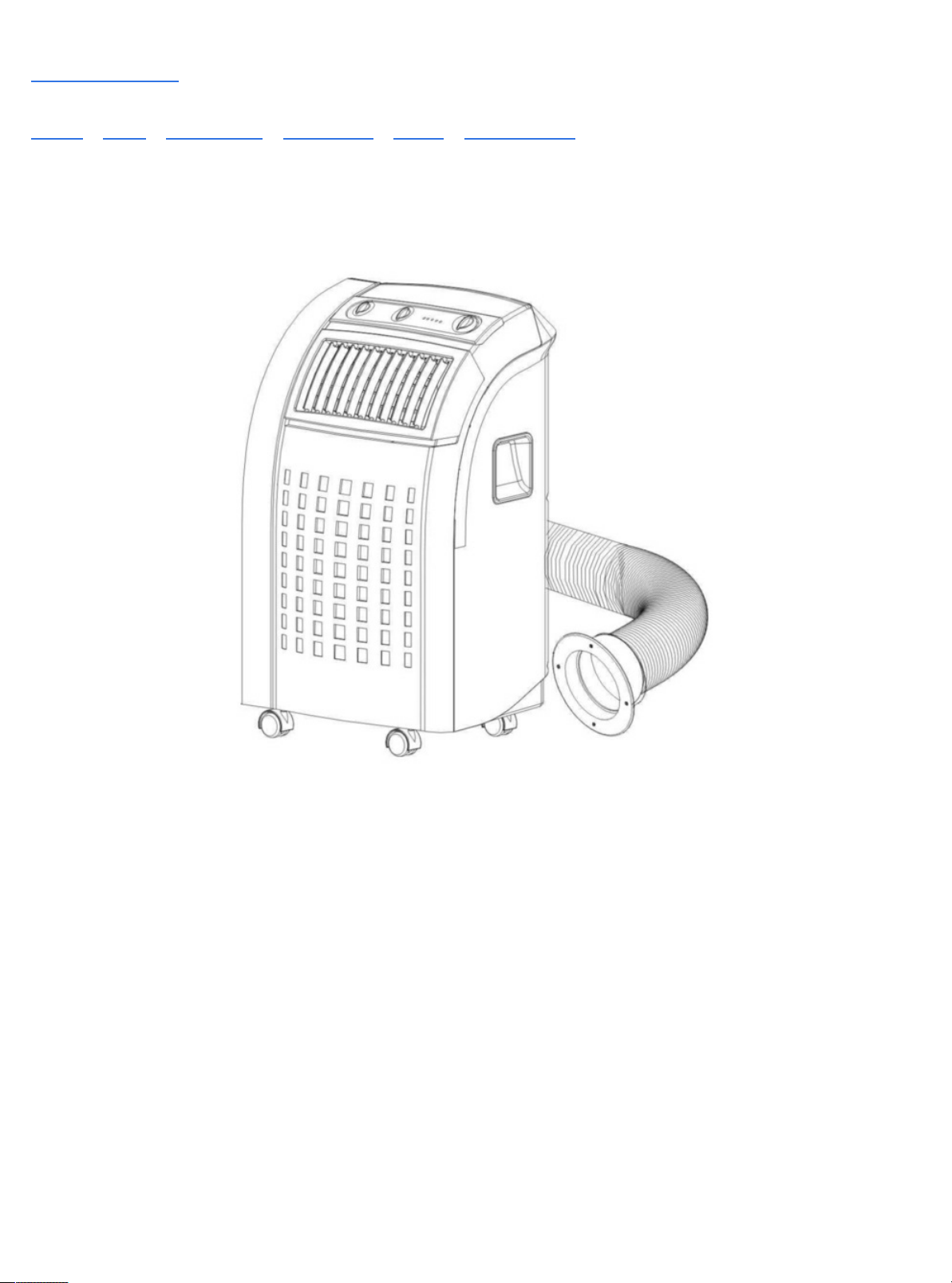
Manuals / Brands / Saivod Manuals / Air Conditioner / Sap 685 / Instruction manual / PDF
SAIVOD SAP 685 INSTRUCTION MANUAL
Quick Links
Specification
Parts
Installation of the Exhaust Pipe
Cooling Only Model
Drainage
Fault Check List
Page 2

Table of Contents
Specification
Before Use
General Safety
Electrical Safety
For Maximum Efficiency
Parts
Front
Back
Accessories
Installation of the exhaust pipe
Using the foam strips
Using the adaptor
Mounting of the exhaust pipe
Installation of the carbon filter
Operation for mechanical type
Cooling only model
Cooling & heating model
Turning ON/OFF
Setting temperature
Regulating air flow direction
Operation for electronic type
Control panel
Setting ventilation speed
Setting timer
Drainage
Maintenance
Cleaning the housing
Cleaning the filter
End of season storage
Fault Check List
Page 3

Page 4
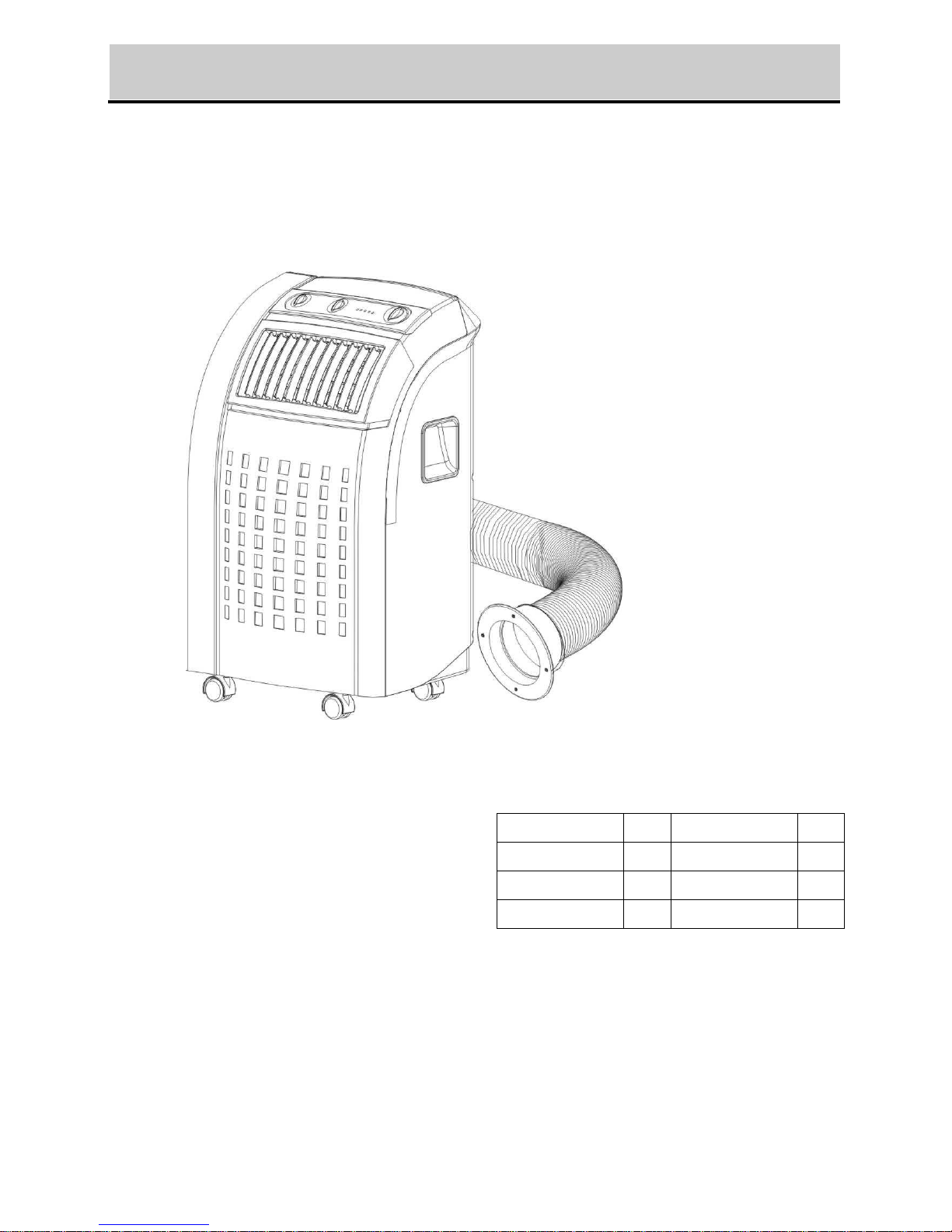
PORTABLE AIR CONDITIONER
Instruction Manual
TC-N028M
TC-T028M
TC-N028MH
TC-T028MH
TC-N028R
TC-T028R
TC-N028RH
TC-T028RH
☆ Read and retain these instructions for future reference
Page 5
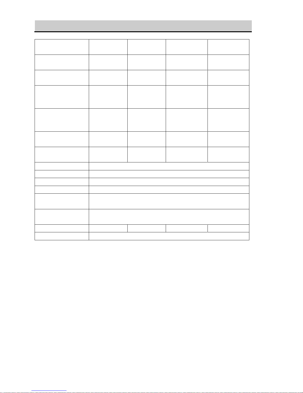
SPECIFICATION
Model no.
TC-N028M
TC-N028R
TC-N028MH
TC-N028RH
TC-T028M
TC-T028R
TC-T028MH
TC-T028RH
Cooling capacity
8500 BTU
2491 W
8500 BTU
2491 W
10000 BTU
2930 W
10000 BTU
2930 W
Heating capacity
N/A
8500 BTU
2491 W
N/A
10000 BTU
2930 W
Power/Ampere
consumption for
cooling*
1010W/ 4.5A
1010W/ 4.5A
1235W/ 5.5A
1235W/ 5.5A
Power/Ampere
consumption for
heating*
N/A
870W/ 3.9A
N/A
1175W/ 5.2A
Air volume (max.
speed)
350 m3/h
350 m3/h
350 m3/h
350 m3/h
Humidity removal
capacity
1.2L/hr
1.2L/hr
1.5L/hr
1.5L/hr
Power supply
220-240V~, 50Hz/1phase
Compressor
rotary
Refrigerant
R410a
Fan speed
2
Timer
Mechanical type: 8 hours
Electronic type: 12 hours
Working temperature
Cooling: 18 ~ 32oC
Heating: 5 ~ 27oC
Net Weight
30 kg
30 kg
32 kg
32 kg
Dimension
430 x 403 x 753 mm (WxDxH)
REMARK:
1. Measuring condition for above is as per EN 14511 : DB=35°C , WB=24°C
*DB = temperature of dry bulb = room temperature, WB = temperature of wet bulb =
relative humidity.
2. Test condition for data in our rating label is as per safety regulation: EN 60335-2-40
3. Current & Fuse : F2L250V or T2L250V
1
Page 6
BEFORE USE
GENERAL SAFETY
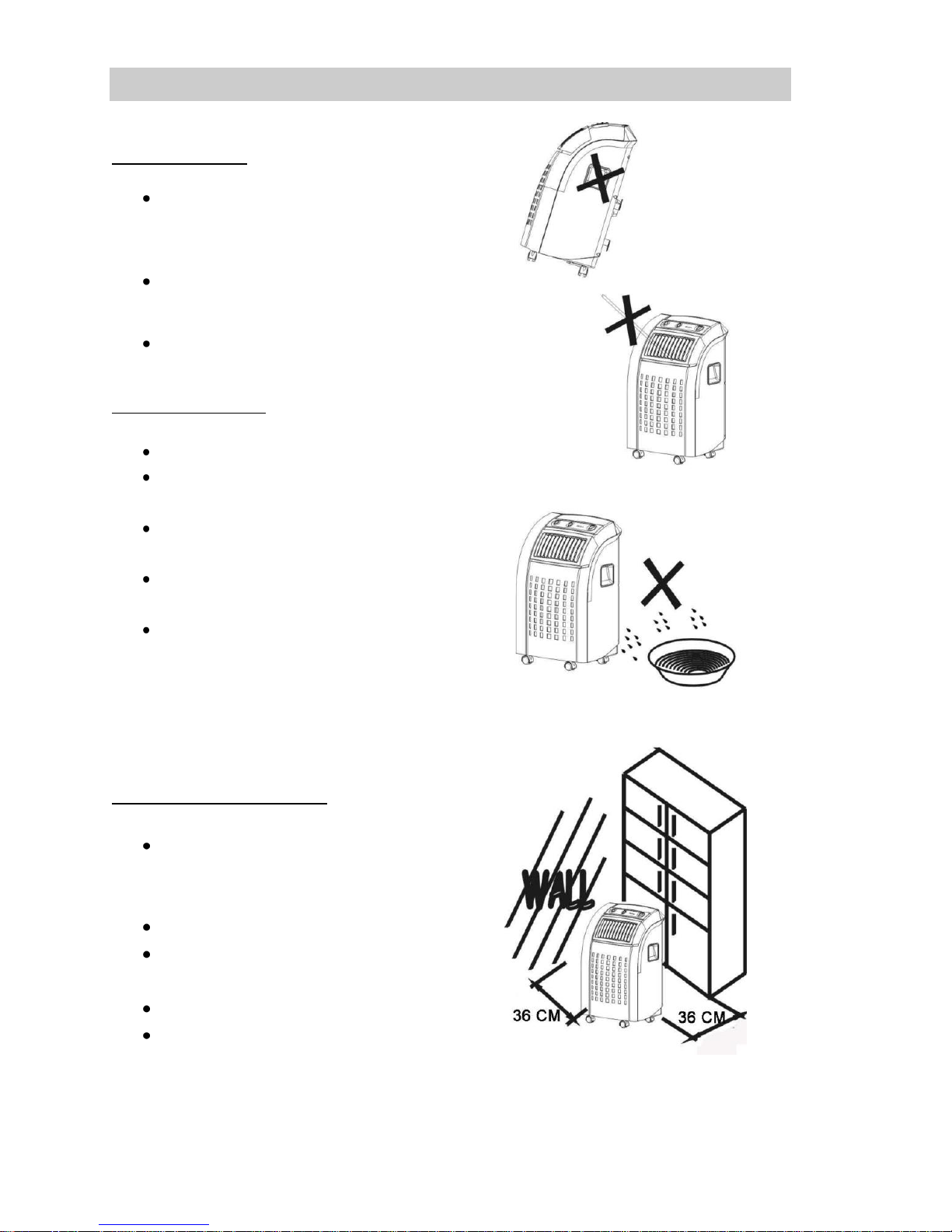
ONLY USE IN THE UPRIGHT POSITION
ON A FLAT LEVEL SURFACE AND AT
LEAST 50cm FROM ANY OBJECTS (Fig
1 & 4).
DO NOT PLACE OBJECTS ON THE UNIT
OR RESTRICT AIR INLET / OUTLET (FIG.
2).
CLOSELY SUPERVISE ANY CHILDREN
AND PETS WHEN UNIT IS IN USE.
ELECTRICAL SAFETY
FOR INDOOR USE ONLY.
SWITCH OFF AND UNPLUG WHEN NOT
IN USE.
DO NOT USE IN HUMID OR WET
ENVIRONMENTS (FIG 3)
DO NOT PULL THE UNIT ALONG BY THE
CORD.
IF THE SUPPLY CORD IS DAMAGED, IT
MUST BE REPLACED BY AN
ELECTRICIAN OR SIMILARLY
QUALIFIED PERSON, TO AVOID
HAZARD.
FOR MAXIMUM EFFICENCY
Do not exceed the recommended
room size 50m3 (typically 20m2 floor
area)
Close doors and windows
Keep curtains of blinds closed
during the sunniest part of the day
Keep filters clean
Once room has reached the
desired conditions, reduce
temperature and ventilation settings
2
FIG. 1
FIG.2
FIG.3
FIG.4
Page 7
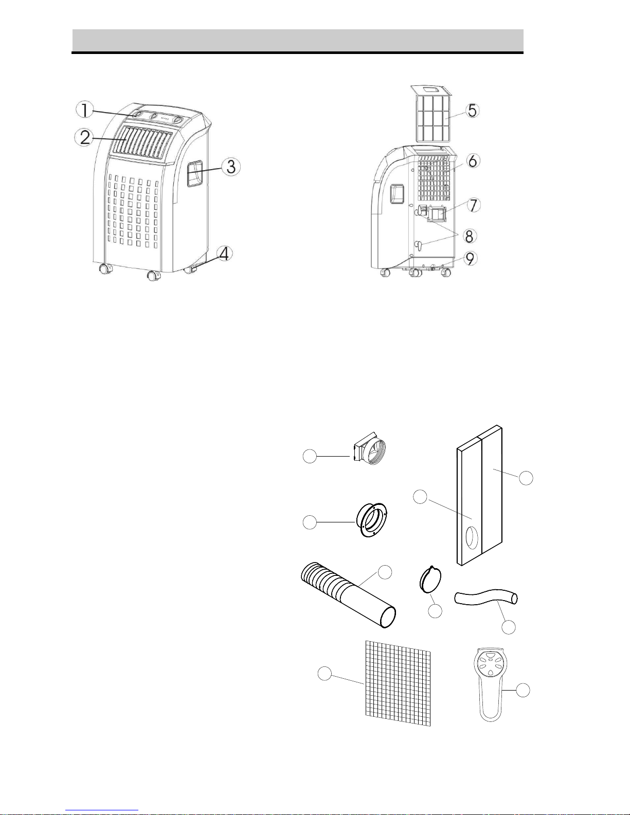
PARTS
Front
Back
1. Control Panel
2. Air outlet
3. Carrying handle
4. Caster
5. Air filter
6. Air inlet
7. Exhaust air outlet
8. Cord storage
9. Water stopper / drainage point
Accessories
10. Inward adaptor - for
insertion over hose and
into back of the air
conditioner.
11. Outward adaptor - for
insertion over hose and
into foam strip (or into
hole in the
wall/window).
12. Exhaust hose
13. Foam strip - for filling
the open window space
and with hole for
connection to exhaust
hose.
14. Foam strip - for filling
the open window space
15. Round cap for filling the
hole in wall/window.
16. Drain tube for
continuous drainage
17. Active carbon filter
18. Remote control (for
electronic type only)
17
13
14
10
11
15
18
12
16
3
Page 8
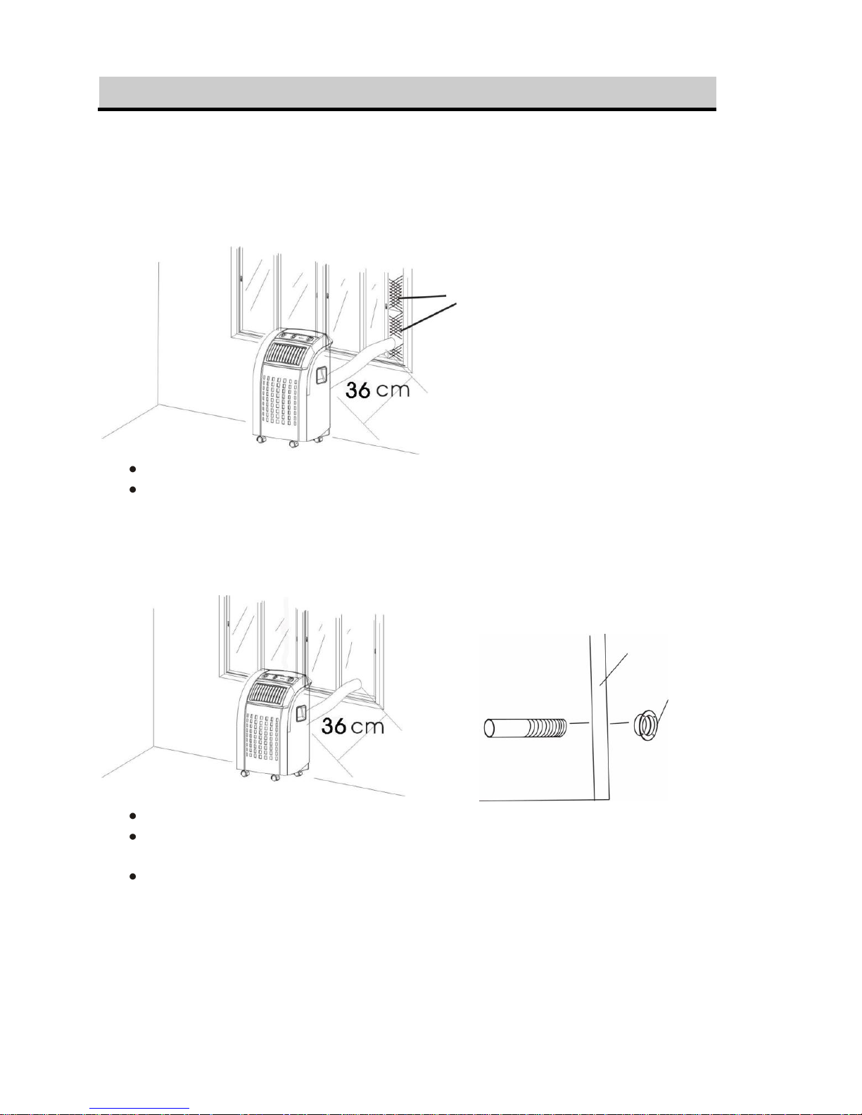
INSTALLATION
Installation of the exhaust pipe
The unit is a portable air conditioner that may be moved from room to room.
1. Using the foam strips
FIG.5
Offer foam strips to the window gap and cut to size if necessary.
Feed exhaust hose through the foam strip and insert strip into window gaps as
shown and slide window across so that foam is held securely. This technique
may also be used for sash windows. Note: Take care to maintain protection
against intruders
2. Using the adaptor
FIG.6
FIG.7
Cut a 130mm diameter hole in the wall or window.
Feed exhaust hose through the window or wall and attach the threaded adaptor
from the outside as shown.
When not in use, plug the hole with the cover provided.
4
Foam strips
Wall or Window
Outward adaptor
Page 9
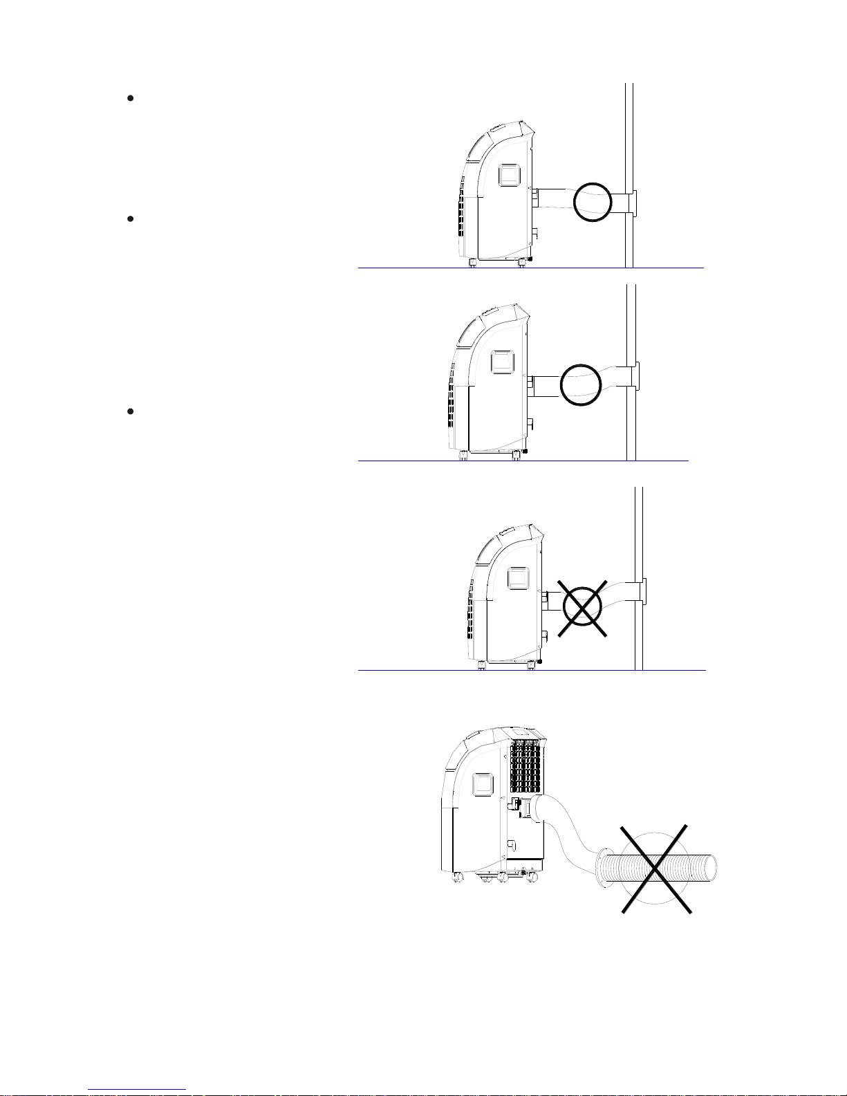
Mounting of the exhaust pipe
Use only the hose
provided and clip
exhaust hose and unit
adaptor to the back of
the air conditioner
Avoid kinks and bends
in the exhaust hose as
this will cause expelled
moist air to build up
causing the unit to
overheat and shut down.
Fig 8 & 9 show correct
position
The hose may be
extended from 300mm
to 1500mm but for
maximum efficiency use
the shortest length
possible.
WARNING!
The length of the exhaust pipe
is specially designed according
to the specification of this
product. Do not replace or
prolong it with your own private
hose as this could cause the
unit to mal-function.
5
FIG.8
FIG.9
FIG.10
FIG.11
Page 10
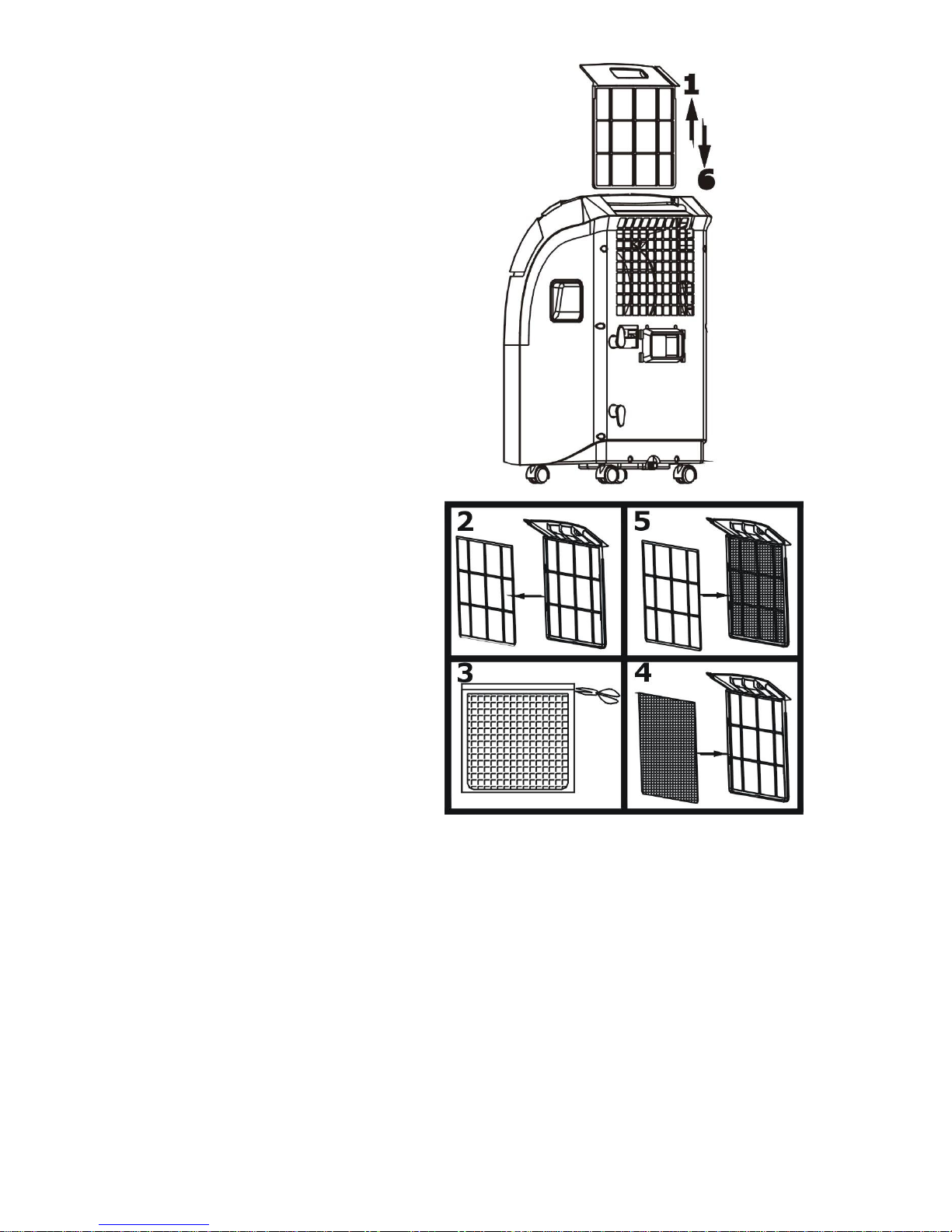
Installation of the carbon filter
1. Remove the filter frame from the
unit.
2. Separate the filter fixer from the
filter frame.
3. Remove the active carbon filter
from its plastic bag.
4. Insert the active carbon filter into
the filter frame.
5. Fix the filter by reassembling the
fixer onto the filter frame.
6. Re-fit the filter frame inside the
unit.
6
Page 11
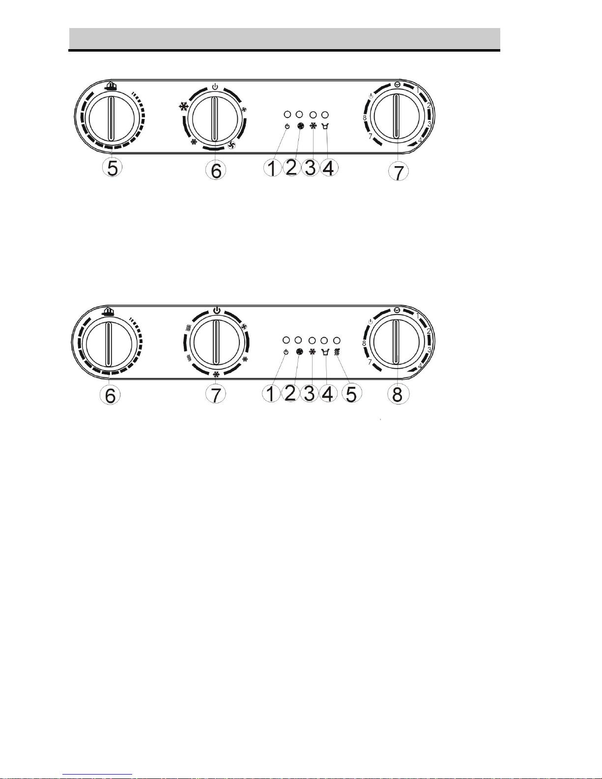
OPERATION for mechanical type
Cooling only model
FIG. 12
1. Power indicator
2. Fan operating indicator
3. Cooling operating indicator
4. 'Full water' indicator
5. Thermostat
6. Speed switch with options for - LOW FAN, HIGH FAN, LOW COOL, HIGH COOL
7. Timer (1-8 hours) as well as ON/OFF switch
Cooling & heating model
FIG.13
1. Power indicator
2. Fan operating indicator
3. Cooling operating indicator
4. 'Full water' indicator
5. Heating operating indicator
6. Thermostat
7. Speed switch with options for - FAN, LOW COOL, HIGH COOL, LOW HEAT,
HIGH HEAT.
8. Timer (1-8 hours) as well as ON/OFF switch
Turning ON/OFF
Set TIMER to ON for continuous operation (the unit will operate as long as it is not
turned off).
Power indicator comes on.
To turn off the unit, turn the TIMER to OFF position.
7
Page 12
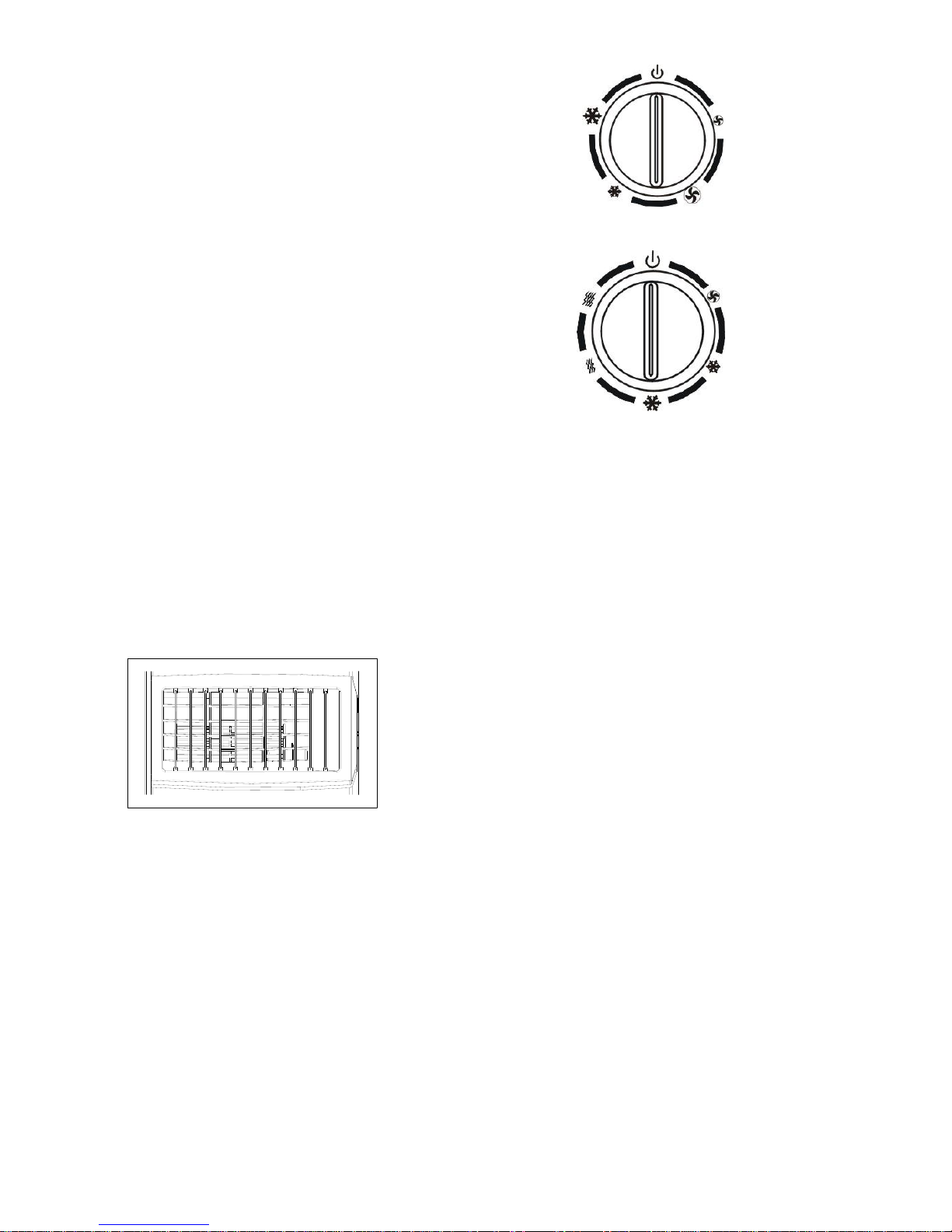
Setting function / ventilation speed
Cooling only models :
Turn the speed switch to select required
setting: LOW FAN, HIGH FAN, LOW
COOL, HIGH COOL
HIGH COOL
LOW COOL
FIG.14
SPEED
LOW FAN
HIGH FAN
Cooling & heating models :
Turn the speed switch to select required
setting: FAN, LOW COOL, HIGH COOL,
LOW HEAT, HIGH HEAT
HIGH HEAT
LOW HEAT
FIG.15
SPEED
HIGH COOL
FAN
LOW COO0L
Setting temperature
Turn the THERMOSTAT to regulate the temperature you desired. The cooling intensity
is increasing clockwise..
Set timer
Set the TIMER to the desired operating time (1 to 8 hours). When the set time has been
reached, the machine will shut off automatically.
Regulating air flow direction
FIG.16
NOTICE !
1. To prolong the compressor's life, after switch-off of the unit, please wait for 3 minutes
(at least) before re-switch.
2. The cooling system will switch off if the ambient temperature is lower than the set one.
The ventilation, however, keeps working on the set level. If the ambient temperature
rises above the selected level, the cooling will return to work.
3. On the contrary, the heating will switch off if the ambient temperature is HIGHER than
the set one (still, the ventilation keeps working on the set level). As the ambient
temperature drops below the selected level, the heating will return to work.
4. This machine is equipped with ANTI-FROST function. While using the heating function
during low temperature, sometimes the heating will stop for a while in order to melt the
frost. As this occurs, just wait for the heating returns to work.
8
Turn the roller on the air vent in horizontal
way to control the air flow direction.
Page 13
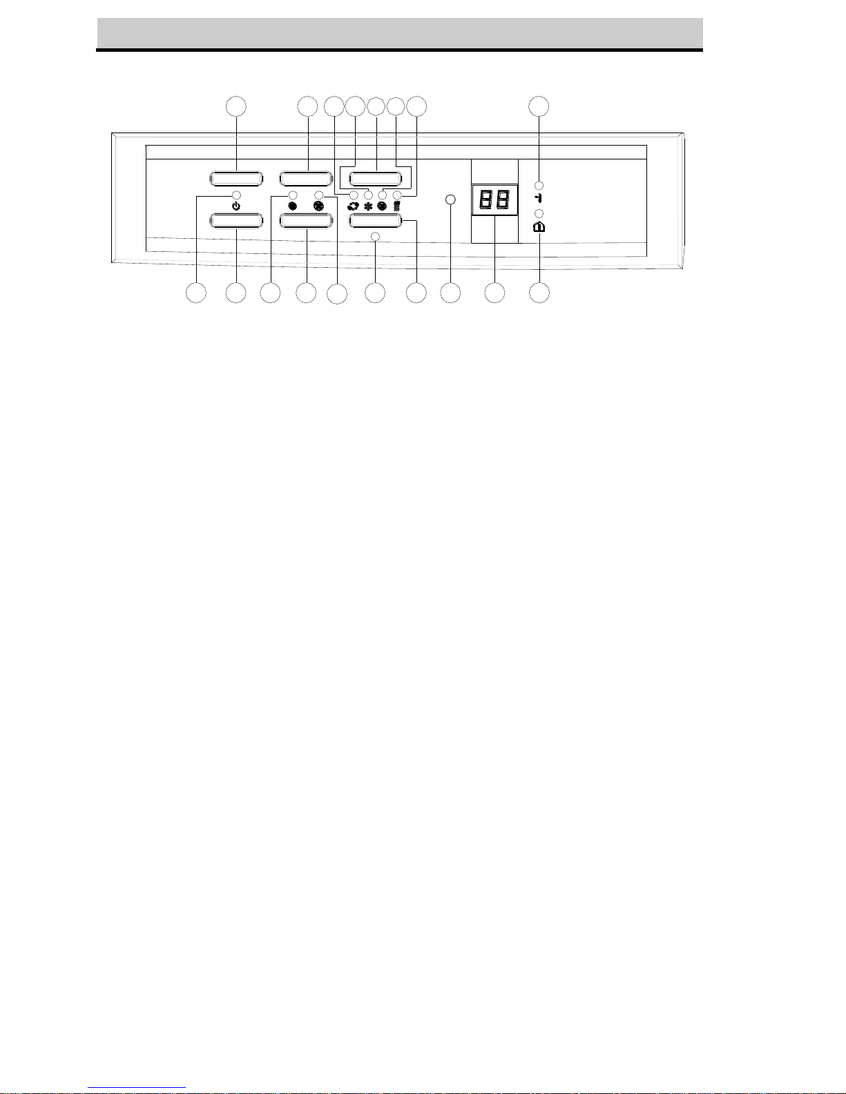
OPERATION for electronic type
Control panel
18
17
16
1511
10
98
7
5
4
2
14
13
12
6
3
1
TIMER
MODE
DOWN
SPEED
UP
I/O
FIG.17
1. I/O(power)button
2. Compressor operation indicator
3. Speed(ventilation)button
4. Low ventilation indicator
5. High ventilation indicator
6. Mode(function)option button
7. Automatic mode indicator
8. Cooling mode indicator
9. Fan mode indicator
10. Heating mode indicator(for cool & heat
model only)
11. Timer button
12. Timer operation indicator
13. `Temperature down` button
14. `Temperature up` button
15. Receiver for Remote Control
16. Display window
17. `Room temperature indicator
18. `Set temperature indicator
Turning ON/OFF
Press ON/OFF button, the unit will start automatically. If the ambient temperature is
- higher than 23oC, the unit will work in cooling model.
- higher than 20oC but below or equal to 23oC, the unit will work in ventilation model.
- below 20oC, the unit will work in heating function (This is for cooling & heating
models only.),
Indicators of the functions in progress come on at the same time. *NOTE! The
COMPRESSOR indicator will only light up as the compressor is in operation.
The display window shows the ambient room temperature.
To turn the unit off, press ON/OFF button again.
Setting mode/function
Press MODE button to select required working mode: automatic, cooling, fan or heating,
(Heating is only available for heating & cooling models.)
The indicator of your selected mode comes on.
Setting temperature
Press 'Temperature up' or 'Temperature down' button to regulate the temperature you
desired.
The display window will show the temperature you set as you press 'Temperature up' or
'Temperature down' button. Otherwise, it will always show the ambient temperature.
The pre-setting temperature of this machine is: 24oC for cooling, 20oC for heating.
9
Page 14
Setting ventilation speed
1. Press SPEED button to choose the ventilation speed you need, high or low. The
indicator of high or low ventilation will light on at the same time.
2. If the unit is in AUTO mode, it will choose the ventilation speed automatically
according to the ambient temperature (the related indicators will light on), at this time,
the speed switch is invalid.
Setting timer
1. Press TIMER button to set the operating hours you desired (1 to 12 hours, the timer
indicator will light on). When the set time has been reached, the machine will turn off
automatically. The display window will show the hour(s) you set as you press TIMER
button. If the timer button is not pressed, the unit will work continuously.
2. By pressing the timer but without turning on the other functions, you can PRE-SET
the time for the machine to work. For example, if you press the timer to '2', the unit
will work automatically after 2 hours.
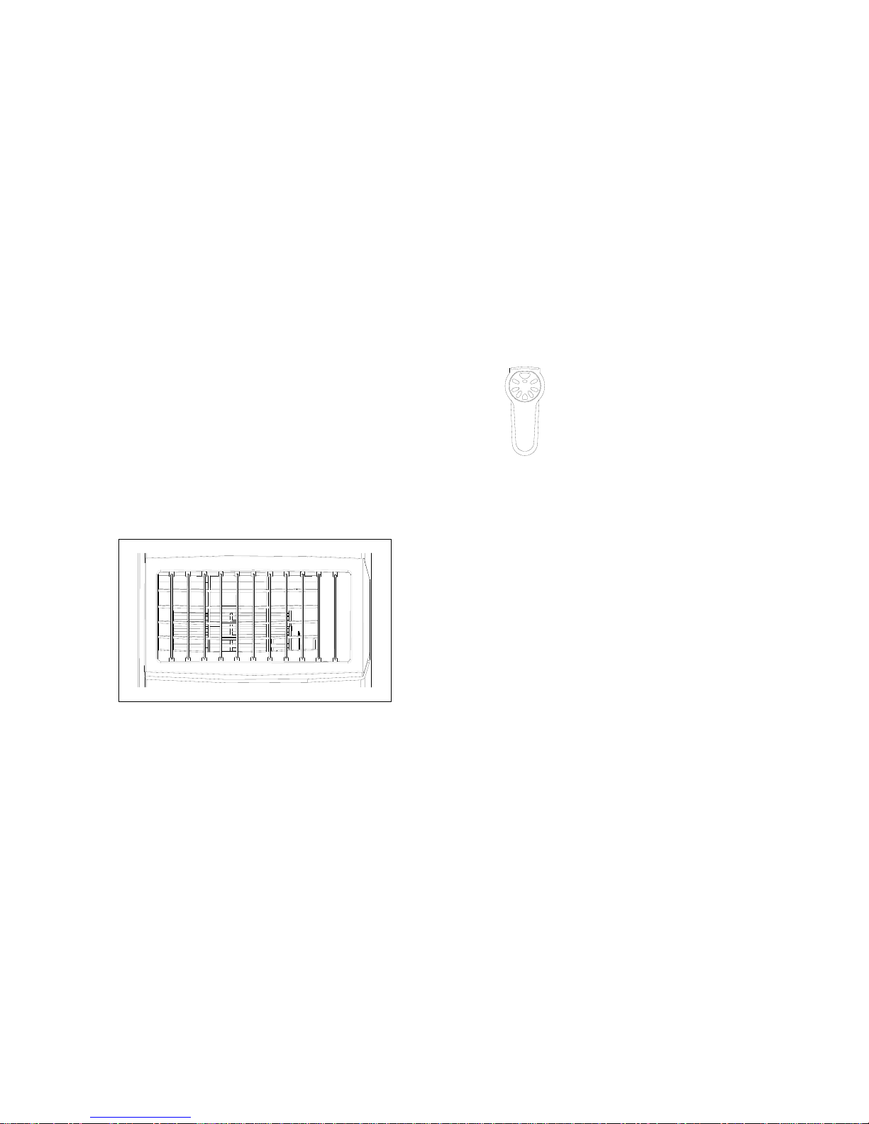
All the above functions can also be performed
with the supplied remote control.
This remote control requires 2 pcs AAA batteries
to operate
FIG. 18
Regulating air flow direction
Turn the roller on the air vent in horizontal
way to control the air flow direction.
FIG.19
NOTICE !
5. To prolong the compressor's life, after switch-off of the unit, please wait for 3
minutes (at least) before re-switch.
6. The cooling system will switch off if the ambient temperature is lower than the set
one. The ventilation, however, keeps working on the set level. If the ambient
temperature rises above the selected level, the cooling will return to work.
7. On the contrary, the heating will switch off if the ambient temperature is HIGHER
than the set one (still, the ventilation keeps working on the set level). As the
ambient temperature drops below the selected level, the heating will return to work.
8. This machine is equipped with ANTI-FROST function. While using the heating
function during low temperature, sometimes the heating will stop for a while in order
to melt the frost. As this occurs, just wait for the heating returns to work.
10
Page 15
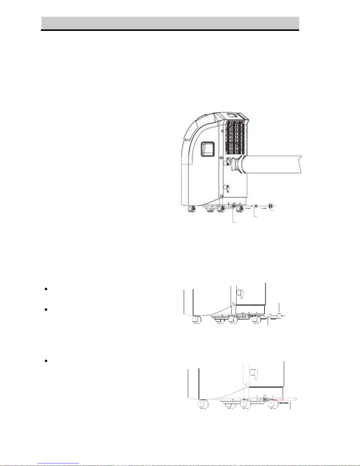
.DRAINAGE
During the process of cooling, some water will be extracted from the air into the unit. If
the reservoir is full:
a. For mechanical type, the compressor will stop, only the fan to circulate the air. The
'FULL WATER' indicator will light now to remind you.
b. For electronic type, both of the compressor and motor will stop. The COMP.
indicator will flash to show you.
To make the cooling work again, please empty the water by one of the following ways:
1. Turn off the air conditioner and avoid
moving it when full.
2. Position a container (a water tray for
example) underneath the drain hole.
3. Remove the drain knob & rubber plug
from the drain hole and allow the water
to drain out.
4. When the container is almost full,
replace the rubber plug in the drain hole
and empty the water tray.
5. Repeat until the unit is emptied.
6. Replace the rubber plug and tighten the
drain knob firmly.
7. Switch on the unit - the full water or
compressor operating indicator should
not be flashing.
FIG.20
If you wish to operate the unit without the need to empty the water tank, please:
Remove the drain knob and rubber
plug and retain for future use.
Connect the drain tube supplied to the
water outlet as shown and locate the
other end into a drain.
The drain tube may be extended by
adding an extension tube and using a
suitable connector.
Rubber plug
Drain knob
FIG.21
Drain tube
FIG.22
11
Water hole
Rubber plug
Drain knob
Page 16
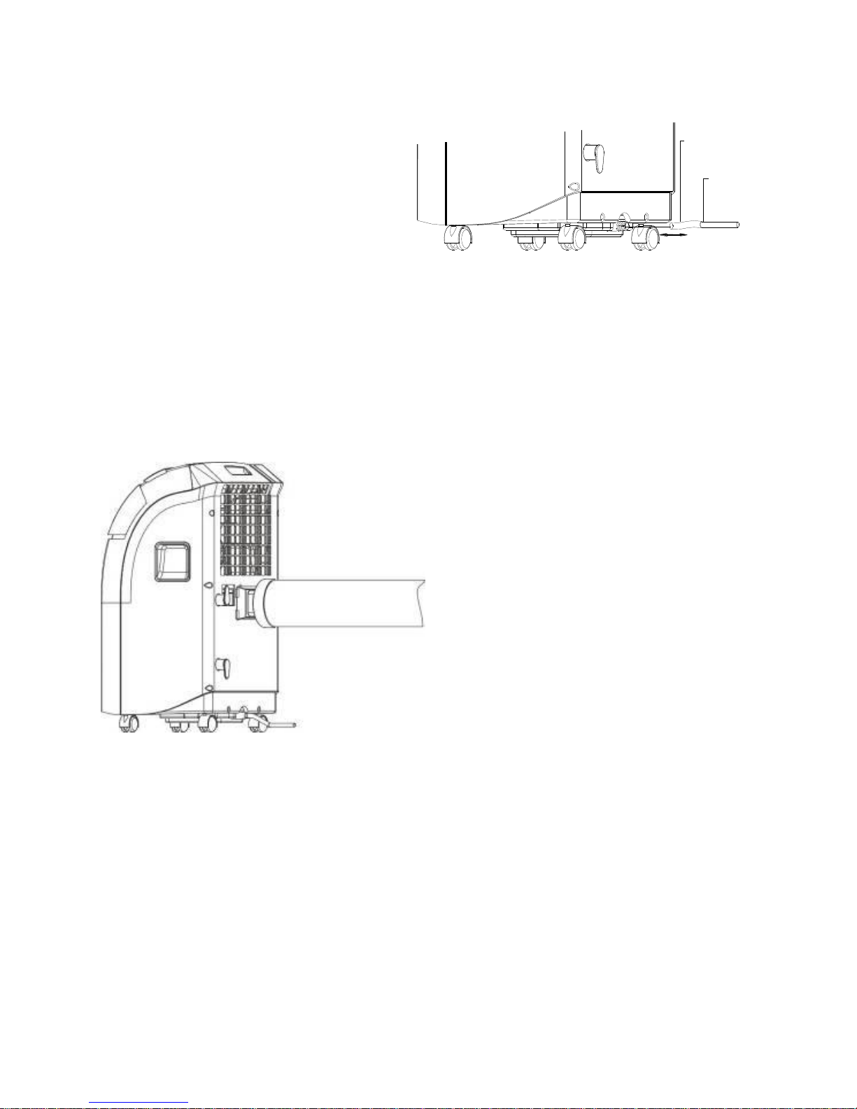
Please note
1. The drain must be at or below
the outlet level.
2. Flashing comp / ‘full water’
indicator will not function in this
mode of drainage.
3. If you want to extend the water
tube, you can connect it with
another tube (OD: 18mm)
Extended
drain tube
(OD:18mm)
Original
drain tube
FIG.23
Special caution for heating function !
FIG.24
While using the heating function, please note:
1. Install the exhaust pipe well, in order to
exhaust the cool air to outdoor. (Please
refer to the instruction manual for
installation method.)
2. Fix the drainage to be continuous one
(i.e. drain the water by water tube).
3. Working range for heating function is 5
to 27oC (for cooling function, it is 18 to
32oC). For temperature outside this
range, the unit may not work properly.
12
Page 17
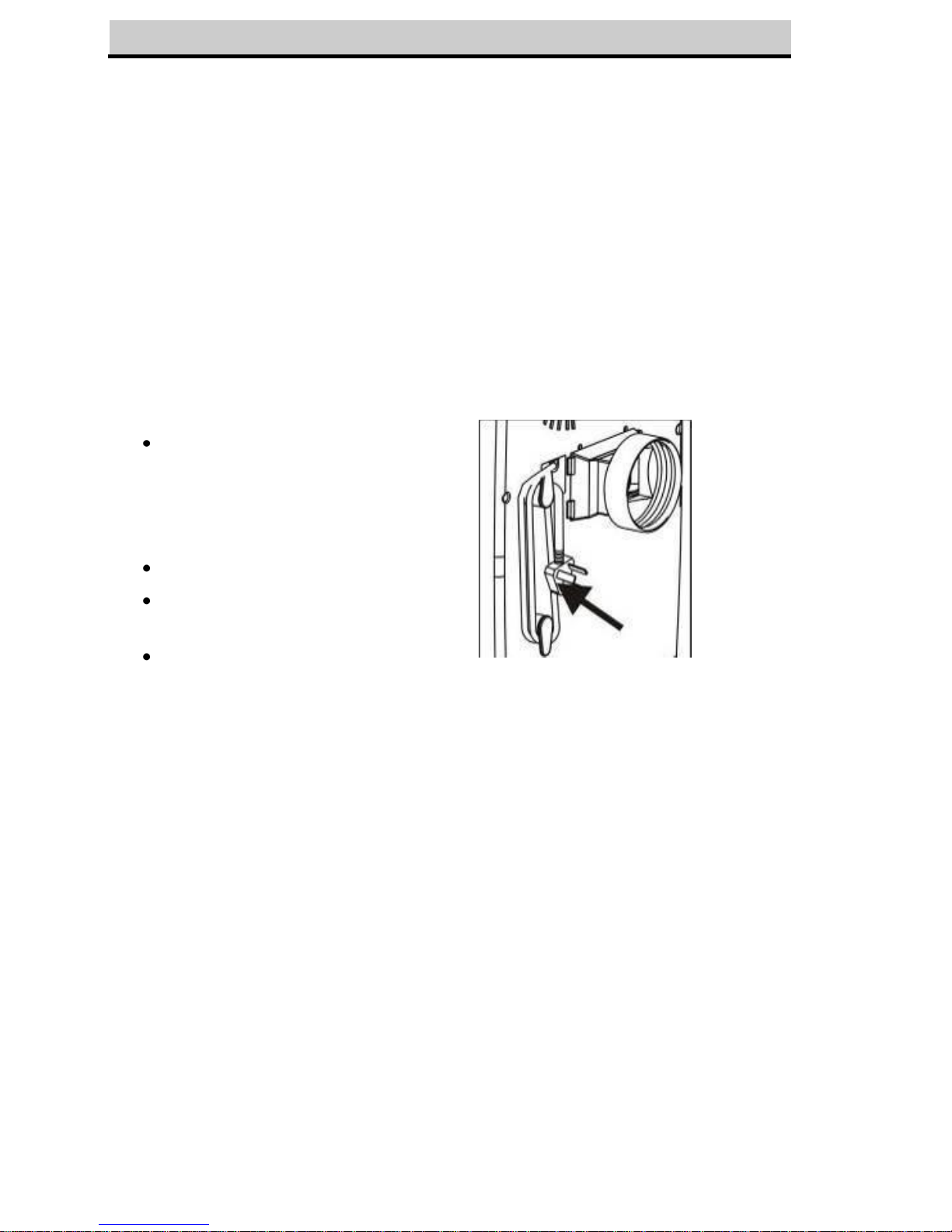
.MAINTENANCE
Always unplug the air conditioner from the mains before cleaning.
To maximize the efficiency of the air conditioner clean regularly.
Cleaning the housing
Use a soft, damp cloth to wipe the body clean.
Never use aggressive chemicals, gasoline, detergents, chemically treated cloths,
or other cleansing solutions. These all could possibly hurt the cabinet.
Cleaning the filter
Use a vacuum cleaner or tap the filter lightly to remove loose dust and dirt from
the filters and then rinse thoroughly under running water (no hotter than 40oC).
Dry thoroughly before replacing.
Notice! Never operate the unit without the filters.
End of season storage
Drain any water in the unit
before completely operating
the unit on ventilation only
mode for a few hours, to
thoroughly dry the inside.
Clean or change the filter
Unplug and store the power
cord as shown
Replace in the original carton
or cover for storage.
FIG.25
13
Cord
Page 18
.FAULT CHECK LIST
The air conditioner does not run
Is the air conditioner plugged in?
Is there a power failure?
Is the comp / ‘full water’ indicator flashing?
Is the room temperature below the set
temperature?
The machine seems to do little
Is there direct sunshine ? (Please put down
the curtain.)
Are too many windows or doors open?
Are there too many people in the room?
Is there something in the room producing lots
of heat?
The machine seems to do
nothing.
Is the filter dusty, contaminated?
Is the air intake or output blocked up?
Is the room temperature below your selected
temperature?
Too noisy
Is the machine positioned unevenly so as to
create vibration ?
Is the floor underneath the machine uneven?
The compressor doesn’t run.
Is so, it is possible the overheat protection of
the compressor is on. Just wait for the
temperature to drop.
☆ Never try to repair or dismantle the unit yourself
14
Page 19

 Loading...