

RS232C (RF4QR/NA GB Operation Board)
Fri. Sept., 06/2002
INSTRUCTION MANUAL
VZU-485/232C
RS-485/232C Interface Board English
RS-485/232C Schnittstellenkarte Deutsch
Carte d’interface RS-485/232C Français
Tarjeta de interfaz RS-485/232C Español
Scheda di interfaccia RS-485/232C Italiano
RS232C (RF4QR/NA GB Operation Board)
Fri. Sept., 06/2002
PRECAUTIONS
CAUTION:
a qualified service person and should conform to
all local codes.
CAUTION: Changes or modifications not
expressly approved by the manufacturer may void
the user’s authority to operate this equipment.
œ Make sure to also read carefully the instruction
manual for the VCR.
œ The contents of this manual may be modified without
prior notice or obligation.
œ Please note that we disclaim any liability for
damages that may have been caused by the use of
this product.
œ Do not use the VCR if smoke or a strange odor
comes from the unit, or if it seems not to function
correctly. Unplug the power cord immediately, then
consult a factory-authorized service center.
œ This manual shows all the commands for Sanyo time
lapse VCRs and real time VCRs equipped with an
RS-232C (or RS-485) connector.
The commands apply to the functions available on
each particular VCR. Therefore, if a function is not
available on your VCR the corresponding command
does not apply to your VCR.
Also, there may be some functions available on your
VCR that cannot be controlled by the command
indicated in this manual. For detailed information,
please read the VCR instruction manual.
Keep this manual handy for later reference.
œ If using the RS-485 interface to operate the VCR, it
is recommended that you use a SANYO brand
system controller.
œ If using the RS-232C interface to operate the VCR
using a computer, separate software is required.
(This software is not sold by SANYO.)
For customers in Canada
This class B digital apparatus complies with
Canadian ICES-003.
This installation should be made by
CONTENTS
PRECAUTIONS . . . . . . . . . . . . . . . . . . . . 1
INSTALLATION OF THE BOARD . . . . . . . . . . . 2
INTERFACE (RS-232C) . . . . . . . . . . . . . . . . 3
INTERFACE (RS-485) . . . . . . . . . . . . . . . . . 4
SETTING FOR RS-485 or RS-232C USE . . . . . . . 5
COMMANDS (RS-232C/RS-485) . . . . . . . . . . . 6
COMMANDS (RS-232C only) . . . . . . . . . . . . 12
COMMANDS (RS-485 only) . . . . . . . . . . . . . 13
COMMANDS TABLE (RS-232C/RS-485) . . . . . . 15
Declaration of Conformity
Model Number : VZU-485/232C
Trade Name : SANYO
Responsible party : SANYO FISHER COMPANY
Address : 21605 Plummer Street,
Chatsworth, California 91311
Telephone No. : (818) 998-7322
œ This device complies with Part 15 of the FCC
Rules. Operation is subject to the following two
conditions:
(1) this device may not cause harmful interference,
and
(2) this device must accept any interference
received, including interference that may
cause undesired operation.
English
1
RS232C (RF4QR/NA GB Operation Board)
Fri. Sept., 06/2002
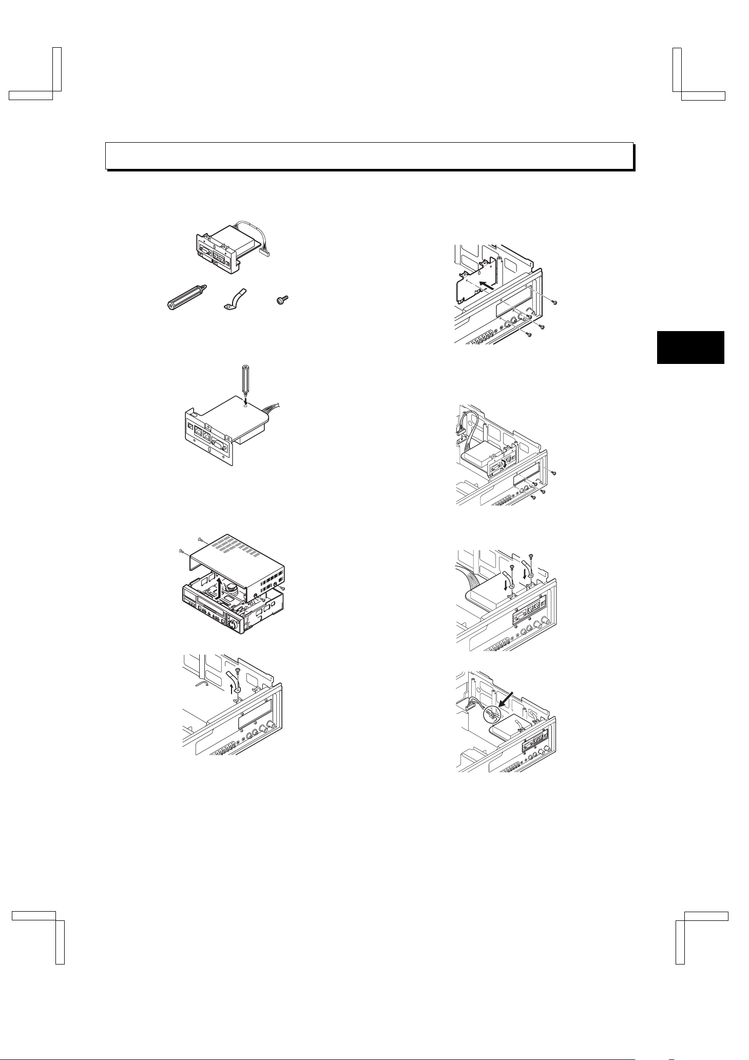
INSTALLATION OF THE BOARD
ACCESSORIES
Optional board
3
Remove the screws (2 to 4) holding the cover.
(Different models have different numbers of screws.
The figure below shows screw positions for a model
with four screws.)
Ground clip
ScrewFixer
Preparation
Attach the fixer to the option board.
Installation
Remove the four screws at the side that are
1
securing the cabinet.
Insert the connector and install the option board.
4
œ Fix the option board to the rear terminal panel.
(Use the screws removed in 3. Be careful not to
mistake the types of screws.)
5 Install the ground clip removed in 2 and the
accessory ground clip. (Use the screw removed in
2 and the accessory screw.)
Remove the screw holding the ground clip.
2
Fix the harness with lugs.
6
Install the cabinet using the screws that were
7
removed in 1.
2
English
RS232C (RF4QR/NA GB Operation Board)
Fri. Sept., 06/2002
INTERFACE (RS-232C)
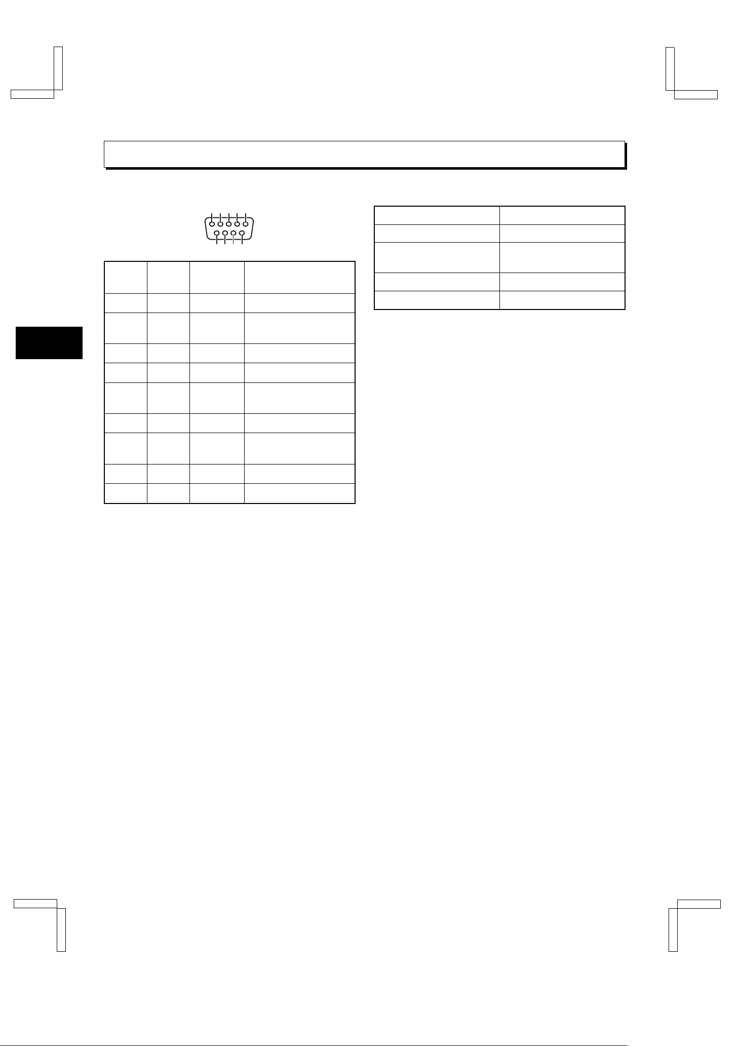
Pin locations
1 2 3 45
7 8
96
Pin
number
The signal transmission is compatible with RS-232C
specifications.
Signal Operation Signal direction
1 —— —
2RXD
3 TXD Send data VCR → Computer
4 —— —
5GND
6 —— —
7RTS
8 —— —
9 —— —
Receive
data
Signal
ground
Request
to send
VCR ← Computer
—
VCR → Computer
Data format
Mode Asynchronous
Character length 8 Bits
Data transmission speed 2400, 4800, 9600 or
19200 bps
Parity check None
Stop bit 1 bit
The data transmission speed can only be set.
To set the data transmission speed, refer to “SETTING
FOR RS-485 or RS-232C USE” on page 5.
Communication protocol
The communication is based on 1 byte units. After the
computer has transmitted 1 byte, it will wait for an
answer from the VCR then send the following byte of
data.
The VCR answer can be 1 byte or more, for example,
the counter position consists of 6 bytes.
Connection
Connect a 9-pin D-SUB cable (sold separately) from
the RS-232C connector on the rear panel to the
computer serial connector.
English
3
RS232C (RF4QR/NA GB Operation Board)
Fri. Sept., 06/2002
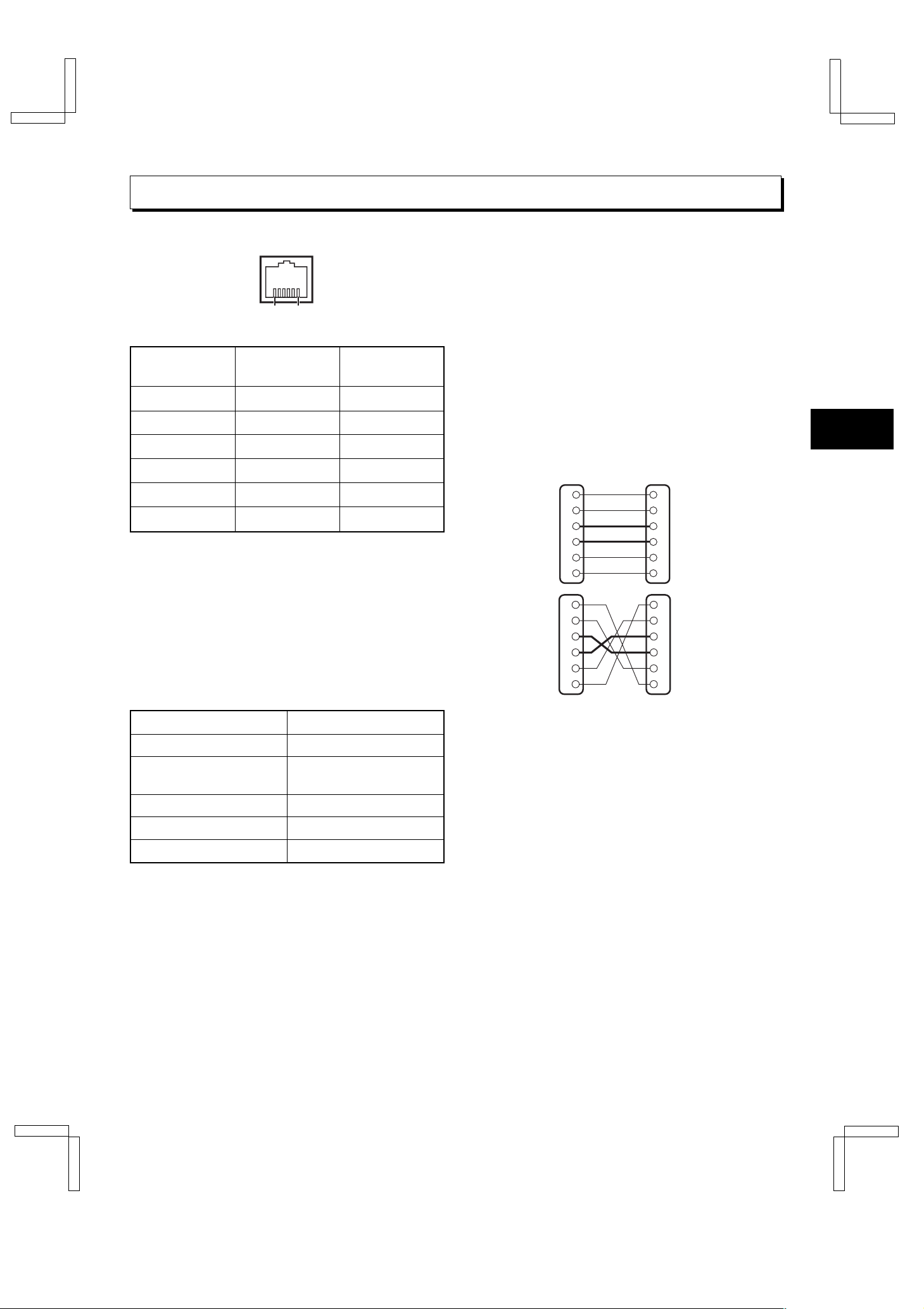
INTERFACE (RS-485)
Pin locations
1 6
NOTE:
Do not connect to phone line.
Pin number
Connector A
signal
Connector B
1 Not used Not used
2 Not used Not used
3AB
4BA
5 Not used Not used
6 Not used Not used
A: Non-inverting driver output/receiver input
B: Inverting driver output/receiver input
Transmission line: 2 conductors
Transmission system: Half duplex
Data format
signal
Transmission protocol
A proprietary protocol (SSP: Security Serial Protocol) is
used. Operates using a Sanyo brand system controller.
Connection
This VCR can use the straight type or crossed type
connecting cable.
If using a straight type cable, connect it from the “A” to
the “A” or from the “B” to the “B” RS-485 connector.
If using a crossed type cable, connect it from the “A” to
the “B” or from the “B” to the “A” RS-485 connector.
Type of cable
Straight type:
Crossed type:
1
2
3
4
5
6
1
2
3
4
5
6
Not used
Not used
Not used
Not used
Not used
Not used
Not used
Not used
1
2
3
4
5
6
1
2
3
4
5
6
Mode Asynchronous
Character length 8 bit
Data transmission speed 2400, 4800, 9600 or
19200 bps
Parity bit None
Start bit 1 bit
Stop bit 1 bit
To set the data transmission speed, VCR address and
TERMINATE
switch, refer to “SETTING FOR RS-485
or RS-232C USE” on page 5.
4
English

RS232C (RF4QR/NA GB Operation Board)
Fri. Sept., 06/2002
SETTING FOR RS-485 or RS-232C USE
The RS-485 interface can be used to operate the VCR
using a SANYO brand system controller. Furthermore,
the RS-232C interface can be used to operate the VCR
using a computer.
NOTES:
œ This can only be used when the RS-485/232C
interface board (VZU-485/232C) is installed.
œ Refer to the instruction manuals for the system
controller and/or the computer.
Setting the Address and Data Transfer
Speed
œ Make this setting without a cassette tape inserted.
Press the
1
or more.
ø “485” or “232” appears on the digital display.
Turn the
2
used, RS-232C or RS-485.
ø “232” or “485” appears on the digital display.
œ When setting “232”, carry out step 3 and then
step 6.
Turn the
3
Turn the
4
000 to 127).
ø The address set appears on the digital display.
Turn the
5
Turn the
6
(19200, 2400, 4800, 9600).
ø The data transfer speed set appears on the
When finished, Press the
7
button.
COUNTER RESET
dial to select the interface being
JOG
SHUTTLE
dial to set the VCR address (from
JOG
SHUTTLE
dial to set the data transfer speed
JOG
digital display.
ring clockwise.
ring clockwise.
NOTE:
œ When the
setting appearing on the digital display is reset to the
default setting.
MENU RESET
button for 3 seconds
COUNTER RESET
button is pressed, the
Settings when using RS-485
Press the
1
Turn the
2
then turn the
3 Turn the
is highlighted, then turn the
clockwise.
4 Turn the
setting, then turn the
Turn the
5
is highlighted, then turn the
clockwise.
Turn the
6
setting, then turn the
Press the
7
Set the
8
the “ON” or “OFF” position
JOG
ø The (OTHERS) menu appears.
JOG
JOG
Y. . . . . . . . . . The VCR status information is
N. . . . . . . . . . The status information is not
JOG
JOG
Y. . . . . . . . . . The VCR alarm information
N. . . . . . . . . . The VCR alarm information
TERMINATE
OFF side . . . Not terminated
ON side . . . . Terminated
button to display the MAIN MENU.
MENU
dial to select the “9.OTHERS” line,
SHUTTLE
<OTHERS>
*ALARM@LOG
*POWER@FAILURE/DEW
*TERMINAL@SET@@@@SET1
*RS-485@SET
@@STATUS@INFO.@@@Y
@@ALARM@INFO.@@@@Y
dial until the “STATUS INFO.” setting
dial to set the “STATUS INFO.”
dial until the “ALARM INFO.” setting
dial to set the “ALARM INFO.”
MENU EXIT
ring clockwise.
SHUTTLE
SHUTTLE
output at the RS-485 connector.
output at the RS-485 connector.
SHUTTLE
(alarm recording start and stop)
and video loss information are
output at the RS-485 connector.
(alarm recording start and stop)
and video loss information are
not output at the RS-485
connector.
button.
switch on the back panel to
ring clockwise.
SHUTTLE
ring clockwise.
ring
ring
English
NOTE:
œ When a warning state (non-recording, mechanical
problem or clog detection) occurs, the warning state
is output from the RS-485 connector. However,
non-recording warning states are not output if “NON
REC” is set to “N” in the (WARNING
OUT/CONTROL SET) menu. In addition, the clog
detection warning state is not output if “CLOG
DETECT.” is set to “N” in the (GENERAL SET) menu.
5

RS232C (RF4QR/NA GB Operation Board)
Fri. Sept., 06/2002
COMMANDS (RS-232C/RS-485)
The received/transmitted (RXD/TXD) signal diagram is
indicated as seen from the VCR side.
Some commands consist of only a single byte.
Note:
The input/output signals for commands that are
complete with a single byte are as follows.
TXD
RXD 0A
The input/output signal diagrams for commands that
are complete with a single byte have been omitted from
the following descriptions, except for return codes.
Cautions Concerning the RS-232C Use
Before using the commands, follow the procedure
below.
Send the T/L TABLE ON command (F6H) to the VCR.
The VCR will respond with ACK (0AH).
The VCR will be in the command receive mode until the
T/L TABLE OFF command (F7H) is sent.
Cautions Concerning the RS-485 Use
œ When a group number is set, if it does not match the
group number, it will not operate.
Commands to Operate the VCR
The following commands are completed in 1 byte.
The VCR will respond with ACK (0AH). Confirm that
ACK (0AH) is returned before sending the next
command.
POWER ON/OFF (7BH)
œ To turn the power ON/OFF.
PLAY (3AH)
œ To start playback.
œ If sent during recording, will start recording check
mode.
STILL/PAUSE (4FH)
œ If sent during playback, will start still mode.
œ If sent during recording, will start recording pause
mode.
STOP (3FH)
œ To go to stop mode.
FF (ABH)
œ To start fast-forward mode.
œ If sent during playback, will start forward picture
search mode.
œ If sent during still mode, will advance of 1 image
(field).
œ If sent after the command to set alarm search
mode, alarm scan or day/time search, will start
the search or scan in the forward direction.
REW (ACH)
œ To start rewind mode.
œ If sent during playback, will start reverse picture
search mode.
œ If sent during still mode, will go back 1 image
(field).
œ If sent after the command to set alarm search
mode, alarm scan or day/time search, will start
the search or scan in the reverse direction.
6
English

RS232C (RF4QR/NA GB Operation Board)
Fri. Sept., 06/2002
COMMANDS (RS-232C/RS-485)
REV PLAY (4AH)
œ If sent during playback, will start reverse
playback.
TIMER ON/OFF (60H)
œ To set the timer recording ON (timer recording
standby)/OFF (timer recording canceled).
QUICK METHOD SECURITY LOCK ON (69H)
œ To engage the quick method security lock.
QUICK METHOD SECURITY LOCK OFF
(6AH)
œ To cancel the quick method security lock.
EJECT (A3H)
œ To eject the cassette.
œ When the VCR receives this command, it will
respond with ACK (0AH), then when the tape has
been ejected, it will respond with CASSETTE
OUT (03H).
A3
RXD
TXD
0A 03
MENU EXIT/AUDIO ON/SEARCH (22H)
œ If sent when a menu is displayed, the menu
screen is canceled.
œ If sent to a time lapse VCR during playback in 12-
or 24-hour mode, will turn on/off the playback
audio.
œ If sent during stop mode, it will switch the search
mode to alarm search, alarm scan, then day/time
search receiving mode.
REC/DUB REQUEST (FAH)
Send this command before sending the REC (CAH)
command.
REC (CAH)
œ To start recording.
œ If sent during single image recording mode, will
record at a set field.
œ Send this command only after sending the
REC/DUB REQUEST (FAH) command and the
VCR responds with ACK (0AH).
FA0ACA
RXD
TXD
0A
SHARPNESS SOFT (4CH)
œ If sent during playback, the image quality
becomes softer.
SHARPNESS SHARP (4DH)
œ If sent during playback, the image quality
becomes sharper.
ON SCREEN ON/OFF (4EH)
œ To set the on-screen display (superimpose
display) “ON”/“OFF”.
If the cassette has no erasure-prevention tab,
recording will not be possible even if the VCR
responds with ACK (0AH). Send the STATUS
SENSE (D7H) command to confirm the state of the
tape.
ALARM SCAN (B1H)
œ To switch to alarm scan mode. Followed by a FF
(ABH) or REW (ACH) command it will start the
scan in the desired direction.
The VCR will go to scan mode, then when the alarm
recording start point is found, it will return
COMPLETION (01H).
If the beginning or end of the tape is reached, it will
return NOT TARGET (05H).
RXD
TXD
B1
0A
AB
0A 01/05
English
7

RS232C (RF4QR/NA GB Operation Board)
Fri. Sept., 06/2002
COMMANDS (RS-232C/RS-485)
To use the following commands, send the command,
wait for the response ACK (0AH), then send the
numeric data value (30H to 39H) 1 byte at a time.
Finally, send the ENTER (40H) command.
The numeric data 30H to 39H corresponds to numbers
0 to 9.
The VCR will go to search mode, then when the
desired target point is found, it will return
COMPLETION (01H).
If the beginning or end of the tape is reached before the
desired target point is found, it will return NOT TARGET
(05H).
ALARM SEARCH (B0H)
œ To switch to alarm search mode. Enter the
desired alarm number and send the ENTER
(40H) command. Send the FF (ABH) or REW
(ACH) command to start the search in the
desired direction.
30H or 31H will search for the first recorded
alarm.
Example: To search for the 10th alarm point recorded
on the tape in the FF direction from the
actual (search start) point.
Commands to Set the VCR
R/P SPEED SET (7EH)
œ To set the recording/playback speed mode
directly.
After sending the R/P SPEED SET (7EH)
command, send 3 bytes of numeric data (30H to
39H), then the ENTER (40H) command.
Example: For 24-hour mode
RXD
TXD
7E
30 32 34 40
0A
0A 0A 0A 0A
COUNTER RESET (E2H)
œ To reset the counter (0:00:00).
COUNTER MEMORY (E3H)
œ To turn ON/OFF the counter memory.
CLOCK ADJUST (E0H)
œ If sent during stop mode, will reset the minutes
and seconds to 00 (to the closest hour). For
example, if sent between 13:30:00 and 14:29:59
the clock is reset to 14:00:00.
RXD
TXD
B0
31 30 40 AB
0A
0A 0A 0A 0A 01/05
DAY/TIME SEARCH (B3H)
œ To switch to day/time search mode. Enter the
desired day and time and send the ENTER (40H)
command. Send the FF (ABH) or REW (ACH)
command to start the search in the desired
direction.
Example: To search for the recording point of the 16th
at 5:10.
RXD
TXDB30A
31 36 30 35 40 AB
0A 0A 0A 0A 0A 0A 01/05
31
0A300A
TRACKING +/V. LOCK +/SHIFT « (50H)
œ If sent during playback, will set the tracking one
step up.
œ If sent during still mode, will set the vertical
alignment one step up.
œ If sent while the menu screen or superimpose
display is being displayed, the operation is the
same as for SHIFT « (63H).
TRACKING –/V. LOCK –/SHIFT ] (51H)
œ If sent during playback, will set the tracking one
step down.
œ If sent during still mode, will set the vertical
alignment one step down.
œ If sent while the menu screen or superimpose
display is being displayed, the operation is the
same as for SHIFT ] (64H).
TRACKING CENTER (52H)
œ If sent during playback, will set the tracking to the
neutral position (center).
8
English

RS232C (RF4QR/NA GB Operation Board)
Fri. Sept., 06/2002
COMMANDS (RS-232C/RS-485)
On-screen Commands
MENU (74H)
œ If sent during stop mode, the main menu is
displayed.
œ If sent while a sub menu is being displayed, the
menu screen is switched.
SHIFT « (63H)
œ If sent while a menu screen is being displayed,
the setting item selection or setting value is
accepted.
œ If sent while the main menu screen is being
displayed, the selected sub menu appears.
œ When a superimpose display is displayed, this
command will move the superimpose display
toward the right. Will not operate during recording.
SHIFT ] (64H)
œ If sent while the clock or timer is being set, the
previous setting item is selected.
œ If sent while a sub menu screen is being
displayed, the main menu appears.
œ If sent while the superimpose display is being
displayed, the display moves down. Will not
operate during recording.
SET +, R/P j (UP) (65H)
œ If sent while a menu screen is being displayed,
the setting item selection or setting will be
changed or the default value will be changed
(increased).
œ To select the tape speed mode.
SET –, R/P l (DOWN) (66H)
œ If sent while a menu screen is being displayed,
the setting item selection or setting will be
changed or the default value will be changed
(decreased).
œ To select the tape speed mode.
MENU RESET (E1H)
œ For each displayed menu, it will reset the menu
settings to the default values.
Commands to Get Information
After the commands to get information are input, the
VCR will respond with the information (data) about
each command.
COUNTER CODE (D0H)
œ 6 bytes indicating the counter position will be
returned.
Example: For –1:23:45, 31H, 31H, 32H, 33H, 34H,
35H will be returned.
Note that the first byte will always indicate
30H for + or 31H for –.
D0
RXD
TXD
31 31 32 33 34 35
HEAD TIME (D2H)
œ 5 bytes indicating the usage duration of the video
head will be returned.
Example: For 00333 hours, 30H, 30H, 33H, 33H, 33H
will be returned.
D2
RXD
TXD
30 30 33 33 33
POWER TIME (D3H)
œ 5 bytes indicating the power connected state
duration will be returned.
Example: For 00777 hours, 30H, 30H, 37H, 37H, 37H
will be returned.
D3
RXD
TXD
30 30 37 37 37
T/L STATUS SENSE (D6H)
œ 5 bytes indicating the VCR status will be
returned. (See page 12 for details.)
RXD
D6
TXD
STATUS SENSE (D7H)
œ 5 bytes indicating the VCR operating mode will
be returned. (See page 11 for details.)
English
RXD
D7
TXD
9

RS232C (RF4QR/NA GB Operation Board)
Fri. Sept., 06/2002
COMMANDS (RS-232C/RS-485)
Other Commands
ENTER (40H)
œ Sent after send all numerical values commands,
this command is used to indicate the end of the
input.
CLEAR (56H)
œ To clear all commands.
œ To cancel an error state.
CLEAR ERROR (41H)
œ To clear the last input (sent) numerical value
command.
œ To cancel an error state.
Return Code
ACK (0AH)
œ Returned by the VCR to indicate it has received
the command.
RXD
TXD 0A
NOT TARGET (05H)
œ Returned if during a search or scan mode the
tape has been completely rewound or advanced
without finding the desired target point. Also
returned when the mode is canceled.
RXD
TXD 0A 05
COMPLETION (01H)
œ Returned when the target point is found after a
search or scan operation.
œ Returned every time a recorded alarm is found
during a scan operation.
RXD
TXD 0A 01
ERROR (02H)
œ When a command of more than 2 bytes cannot
be received past the second byte by the VCR, it
will return an ERROR (02H) to indicate that the
command is not received. Any other command
send after an ERROR (02H) will not be received.
However, the VCR status will be returned. To
cancel this state, sent the CLEAR ERROR (41H)
or CLEAR (56H) command.
RXD
TXD 0A 02
40
NAK (0BH)
œ Response when an undefined (or non existent)
command is sent.
RXD
TXD 0B
10
English

RS232C (RF4QR/NA GB Operation Board)
Fri. Sept., 06/2002
COMMANDS (RS-232C/RS-485)
STATUS SENSE (D7H)
Bit assignation for each byte of data
Byte 1
BIT Content when the bit is 0.
ERROR When an incorrect
command is received. The
CLEAR ERROR (41H) or
0
1 Undefined Always 0.
2 Undefined Always 0.
CASSETTE OUT No cassette loaded in the
3
REC INHIBIT Loaded cassette has no
4
5 Undefined Always 0.
6 Undefined Always 0.
7 Undefined Always 1.
CLEAR (56H) command
must be sent before any
other command can be
accepted.
VCR.
erasure-prevention tab.
Byte 2
BIT Content when the bit is 0.
0 Undefined Always 0.
1 Undefined Always 0.
2 Undefined Always 0.
WARNING Something wrong with the
3
4 Undefined Always 0.
5 Undefined Always 0.
6 Undefined Always 0.
7 Undefined Always 0.
VCR.
Byte 3
BIT Content when the bit is 0.
0 Undefined Always 0.
1 Undefined Always 0.
REPEAT MODE Autorepeat recording
2
3 Undefined Always 0.
ON-SCREEN ON The superimpose display
4
COUNTER
5
MEMORY
6 TIMER REC ON Timer recording mode ON.
7 Undefined Always 0.
mode.
appears on the screen.
The counter memory of
the unit is ON.
Byte 4
BIT Content when the bit is 0.
0 Undefined Always 0.
1 REC MODE Recording.
2 EJECT Ejecting the cassette.
3 RVS PLAY In reverse playback mode.
4 STOP MODE In stop mode.
5 REW MODE Rewinding.
6 FF MODE Fast-forwarding.
7 PLAY MODE Playing back.
Byte 5
BIT Content when the bit is 0.
STILL MODE In playback still or field
0
1 PAUSE MODE In record pause mode.
2 Undefined Always 0.
advance mode.
English
3 Undefined Always 0.
REVIEW MODE Reverse picture search
4
CUE MODE Forward picture search
5
6 Undefined Always 0.
7 Undefined Always 0.
11
mode.
mode.

RS232C (RF4QR/NA GB Operation Board)
Fri. Sept., 06/2002
COMMANDS (RS-232C/RS-485)
T/L STATUS SENSE (D6H)
Bit assignation for each byte of data
Byte 1-2-3
Recording/playback speed mode
Example:
Byte 1-2-3: Data indicating the tape speed mode in the
VCR.
24-hour mode → BYTE 1 = 30
BYTE 2 = 32
BYTE 3 = 34
NOTE: The following conditions indicated by each bit
are true when 1 is returned, false when 0 is
returned.
Byte 4
BIT Content when the bit is 0.
AUDIO ON Time lapse VCR audio
0
1 POWER ON The power is ON.
2 Undefined Always 0.
3 Undefined Always 0.
TIMER REC
4
MODE ON
SERIES REC
5
MODE ON
1SHOT REC
6
MODE ON
ALARM REC
7
MODE ON
playback mode on.
Timer recording mode ON
or timer recording standby
mode.
Series recording mode ON.
Single image recording
mode ON.
Alarm recording mode ON.
Byte 5
BIT Content when the bit is 0.
0 Undefined Always 0.
ALARM SEARCH
1
SET
ALARM SEARCH
2
MODE
3 Undefined Always 0.
ALARM SCAN
4
MODE
5 T/D SEARCH SET Day/time search being set.
T/D SEARCH
6
MODE
7 MENU MODE Menu is displayed.
Alarm search being set.
Alarm search mode ON.
Alarm scan mode ON.
Day/time search mode ON.
COMMANDS (RS-232C only)
T/L TABLE ON (F6H)
œ To start the VCR control.
T/L TABLE OFF (F7H)
œ To end the VCR control.
CASSETTE OUT (03H)
œ Response when the cassette is ejected.
A3
RXD
TXD 0A 03
12
ALARM IN (06H)
œ Response after an alarm has been input.
RXD
TXD 06
VCR INQ (FBH)
œ To confirm that the connect unit is a VCR. If so,
the VCR will respond with ACK (0AH).
English

RS232C (RF4QR/NA GB Operation Board)
Fri. Sept., 06/2002
COMMANDS (RS-485 only)
GROUP SET (6CH)
œ Sent when grouping (making group numbers).
After the VCR responds with ACK (0AH), send
the 2 byte group number.
Example:
RXD
TXD
Setting group number 5.
6C0A20
0A000A
GROUP CHECK (6DH)
œ Returns the group number.
Example:
RXD
TXD
For group number 2.
6D
04 00
GROUP CLEAR (6EH)
œ Clears the group number. After the VCR
responds with ACK (0AH), send the 2 byte group
number.
Example:
RXD
TXD
For group number 8.
6E0A00
0A010A
STATUS LOG 1 (BFH)
œ This is the header for the mode change data such
as when the VCR is operated that the VCR
returns to the system controller when using
RS-485. (See page 14 for details.)
STATUS LOG 2 (BEH)
œ This is the header for the mode change data such
as when the VCR is operated that the VCR
returns to the system controller when using
RS-485. (See page 14 for details.)
MENU UPLOAD (D8H)
œ This sends the menu settings for the VCR to the
system controller. (The setting details are stored
by the system controller.)
D8
RXD
TXD
0A 40
MENU DOWNLOAD (E8H)
œ This sends the menu settings for the VCR that
are being stored by the system controller to the
VCR, and this changes the VCR menu settings.
E8 40
RXD
TXD
0A 0A0A 0A
SET ON (7CH)
œ Whatever the present state, power on or off, will
set the VCR to power on state.
SET OFF (7DH)
œ Whatever the present state, power on or off, will
set the VCR to power off state.
CLOCK (E9H)
œ This sets the VCR clock based on the clock data
sent from the system controller.
E9
RXD
TXD
40
English
13

RS232C (RF4QR/NA GB Operation Board)
Fri. Sept., 06/2002
COMMANDS (RS-485 only)
When using the RS-485 interface and operations are
carried out at the VCR, the VCR automatically returns a
2-byte data code based on the current setting.
RXD
TXD
BE/BF
First byte: Header (BEH or BFH)
Second byte: State change information
The second byte indications are as follows:
When the first byte is “BEH”
Bit 0 ~ 7
Mode indication.
BIT Content when the bit is 0.
VIDEO LOSS The video input signal is
0
1 THREAD CHECK Thread check start.
TAPE
2
MANAGEMENT
3 Undefined Always 0.
4 Undefined Always 0.
5 Undefined Always 0.
6 Undefined Always 0.
no longer present (VIDEO
LOSS).
Tape management start.
When the first byte is “BFH”
Bits 0, 1, 2, 3, 4
State information.
00000No change.
10000No tape, power is on.
01000No tape, power is off.
11000Tape present, power is on.
00100Tape present, power is off.
10100Timer recording standby mode.
01100Still image playback start.
11100Recording pause.
00010Playback start.
10010Recording start.
01010Reverse playback start.
11010Forward picture search start.
00110Reverse picture search start.
10110Fast forward start.
01110Rewind start.
11110Field advance start.
00001Reverse field advance start.
7 Undefined Always 0.
Bits 5, 6
Alarm recording start and stop.
00Normal
0 1 Alarm recording start
1 0 Alarm recording stop
Bit 7
Warning state.
A flat (non-recording, mechanical trouble or
1
clog detection) has occurred.
0Normal
14
English

RS232C (RF4QR/NA GB Operation Board)
Fri. Sept., 06/2002
COMMANDS TABLE (RS-232C/RS-485)
ON
OFF
REC/DUB
T/L TABLE
T/L TABLE
REQUEST
MENU
CLOCK
ADJUST
CODE
COUNTER
ALARM
ALARM
SEARCH
TIMER
ON/OFF
«
RESET
SCAN
]
RESET
COUNTER
COUNTER
POWER
HEAD TIME
DAY/TIME
MEMORY
TIME
SEARCH
EJECT
MENU4
SHIFT «
SHIFT ]
R/P j
SET +,
SENSE
SENSE
STATUS
T/L STATUS
R/P l
SET –,
MENU
MENU
CLOCK
DOWNLOAD
UPLOAD
QUICK METHOD
REC
LOCK ON
SECURITY
SECURITY
QUICK METHOD
FF VCR INQB
POWER
ON/OFF
LOCK OFF
SET ON REWC
SET
GROUP
SET OFFD
CHECK
GROUP
LOG2
STATUS
SET
CLEAR
LOG1
STATUS
R/P SPEED
GROUP
: RS-232C or RS-485 only commands.
English
V. LOCK +,
TRACKING +,
0ENTER
0123 4 5 6 789A B C D E F
0
SHIFT
TRACKING –,
CLEAR
SHIFT
V. LOCK –,
TRACKING
ERROR
1
COMPLETION
1
2
AUDIO ON/
MENU EXIT/
ERROR
2
CENTER
3
SEARCH
CASSETTE
3
OUT
4
5
NOT
TARGET
5
ALARM IN 6 CLEAR
6
7
7
15
REV
PLAY
88
9
ACK PLAY
9
A
SHARPNESS
NAK
SOFT
SHARP
SHARPNESS
STILL/
ON/OFF
ON SCREEN
PAUSE
STOP
F
E
 Loading...