

INSTRUCTION MANUAL
VZU-232CA
RS-232C Operation Board
RS-232C-Steuerkarte
Carte d’opération RS-232C
Tarjeta de control RS-232C
Scheda operativa RS-232C
English GB
Deutsch D
Français F
Español E
Italiano I
CS
Before installing the RS-232C operation board, be sure to carefully read this manual,
and follow the in structions.
Please keep it in a safe place, in case it becomes necessary later on.

PRECAUTIONS
CONTENTS
When install ed in a time lapse VCR o r real
time VCR, the RS- 23 2C op eration board
permits to control the VCR from a
computer.
Make sure to also read carefully the
•
instructio n m an ua l fo r th e VC R.
Do not use this board on VCRs other
•
GB
than the ones recommended by us.
For a complet e li st of co m pa t i bl e V CR s,
please consult your dealer or
factory-authorized service centre.
The contents of this manual may be
•
modified without prior notice or
obligation.
Please note that w e disclaim any liability
•
for damages that may have been
caused by the use of this product.
Do not use the video tape recorder if
•
smoke or a strange odor comes from
the unit, or if it seems not to function
correctly. Unplug the power cord
immediatel y, then consult a
factory-authorized service center.
The production number is an important
informatio n fo r quality control.
When you purchase the product, make
sure that the production number on the unit
match.
PRECAUTI ONS . . . . . . . . . . . . . . . . . . . 1
INSTALLATION . . . . . . . . . . . . . . . . . . . 2
9-PIN REMOTE CONTROL
INTERFACE . . . . . . . . . . . . . . . . . . 3
COMMANDS. . . . . . . . . . . . . . . . . . . . . . 4
COMMANDS TABLE . . . . . . . . . . . . . . 13
1
INSTALLATION
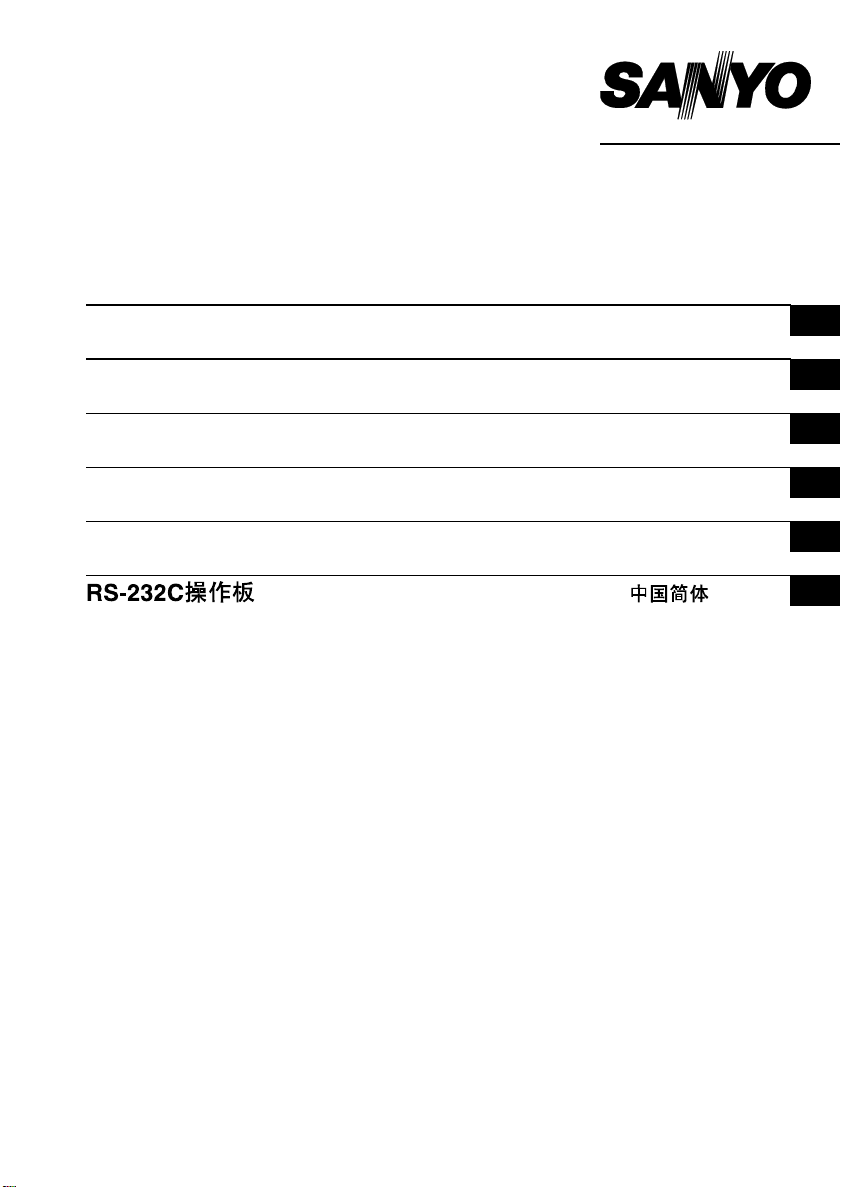
1 Unplug the VCR power cord.
Disconnect all cables connecting the
•
VCR to other units.
2 Remove the 3 screw s fi xi ng the cov er
of the RS-232C operation board slot,
on the back of the VCR.
3 Remove the cover.
4 Plug the 8-pin connector into the 8-pin
socket on the RS- 23 2C op eration
board.
CAUTION: When making the
connection, be sure to align the
protuberance on the connector with the
groove on the socket.
5 Insert the RS-232C operation board
into the VCR.
When insertin g th e bo ard, check the
following:
Make sure no cable or other is not
•
pinched by the boar d .
RS-232C operation board
operation check
1 Make all necessary connections to the
VCR.
2 Plug the power cord plug into an AC
outlet.
3 Press the VCR MENU button. G o to
the Menu (OTHER).
4 Make sure that "RS-232C 1200" is
displayed of the sc reen.
If displayed, the unit will operate
•
correctly.
If the display in dicated above does
•
not appear, the RS-232C operation
board will not func ti on . Re-install the
board, making sure the installation
and the connection are correct.
GB
6 Install and tighten the screws.
After installing the RS-232C operation
board, follow the steps below to make
sure it operates cor r e ct ly .
2
9-PIN REMOTE CONTROL INTERFACE
When the RS-232C operation board is
installed in the VC R, the VCR can be
controlled fr om a co m puter connected to
the rear RS-232C connector.
Depending on the VCR used, some
commands may not be available.
For a complete list of VCRs compatible
with this RS-232 C Op er ation Board, please
GB
consult your dealer or factory-authorized
service centre.
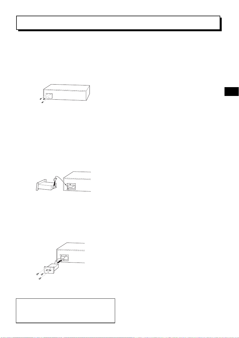
9-pin connector layout
Pin
number
Signal Operation Signal direction
2RXD
3TXD
4DTR
5GND
Receive
data
Send
data
Normally
1
Signal
ground
VCR ← Computer
VCR → Computer
The signal transm ission is compatible with
RS-232C spec if ic ations.
VCR Computer
TXD 3 Pin TXD
RXD 2 Pin RXD
GND 5 Pin GND
7 Pin
8 Pin
Data format
Mode Asynchronous
Character length 8 Bits
Data transmission
speed
Parity check None
Stop bit 1 bit
1200, 2400, 4800 or
9600
The data transmission speed only can be
set.
To set the data transmission speed, please
refer to the VCR section "OTHER settings".
3

COMMANDS
PREPARATION
Before using the commands, follow th e
procedure belo w.
Send the T/L TABLE ON command (F6H)
to the VCR.
The VCR will respond with ACK
•
(0AH).
The VCR will be in the command
•
receive mode unti l th e T/ L TABL E
OFF command (F7H) is sent.
T/L TABLE ON (F6H)
To start the T/L (Tim e Lapse VCR)
•
control.
T/L TABLE OFF (F7H)
To end the T/L (Tim e Lap se VCR)
•
control.
COMMANDS TO OPERATE
THE VCR
The following commands are completed in
1 byte.
The VCR will respond with ACK (0AH).
Confirm that ACK (0AH) is return ed bef or e
sending the next command.
POWER ON/OFF (7BH)
To turn the power ON/OFF.
•
PLAY (3AH)
To start playback.
•
If sent during recording, will start
•
recording ch ec k mode.
STILL (4FH)
To go to pause/still mode.
•
STOP (3FH)
To go to stop mode .
•
FF (ABH)
To start fast-forward mode.
•
If sent durin g pl ay ba ck , w il l start
•
CUE (fast-for w ar d pl ay ba ck ) m od e.
If sent durin g a pl ay ba ck pause, will
•
advance of 1 fram e.
If sent during alarm search, alarm
•
scan or date/time search receiving
mode, will set the search or scan
direction to the forward directio n.
REW (ACH)
To start rewind mode.
•
If sent durin g pl ay ba ck , w il l start
•
REVIEW (reverse playba ck ) m od e.
If sent durin g a pl ay ba ck pause, will
•
go back 1 frame.
If sent during alarm search, alarm
•
scan or date/time search receiving
mode, will set the search or scan
direction to the reverse dire ction.
GB
4

COMMANDS
GB
REV PLAY (4AH)
If sent durin g pl ay ba ck , w il l start
•
reverse playback .
Canceled by the PLAY command.
•
TIMER ON/OFF (60H)
To set the timer recording ON (timer
•
recording)/OFF (t im e r re cord in g
canceled).
SECURITY LOCK ON (69H)
To engage the sec urity lock.
•
SECURITY LOCK OFF (6AH)
To cancel the security lock.
•
EJECT (A3H)
To eject the cass et te .
•
AUDIO/SEARCH (22H)
If sent durin g 12 /2 4-Hour playback
•
mode, will turn ON/OFF the
playback sound.
If sent during stop mode, it will
•
switch the sear ch mo de to al ar m
search, alarm scan, then date/time
search receiving mode.
If sent when a menu is displayed,
•
will cancel the menu display.
REC (CAH)
To start reco r d in g.
•
If sent durin g 1 fr am e rec ording
•
mode, will record 1 frame.
Send this command only after
•
sending the REC/DUB REQUEST
command and the VC R r esponds
with ACK (0AH).
If the cassette has no
erasure-prevention tab, recording will
not be possible even if the VCR
responds with ACK (0AH). Send the
STATUS SENSE (D7H) command to
confirm the st at e of the tape.
REC/DUB REQUEST (FAH)
Send this command before sending the
REC (CAH) command.
After sending the following command, the
VCR will respond with ACK (0AH).
ALARM SCAN (B1H)
To switch to alarm scan receiving
•
mode.
If a FF (ABH) or REW (ACH)
command is received the alarm
scan will start in the appropriate
direction.
RXD
TXDB10A
AB
0A 01/05
5

COMMANDS
After sending the following command, the
VCR will respond with ACK (0AH), then
resend a data input command (40H) of 1
byte numeric data (30H to 39H).
The numeric data 30H to 39H corresponds
to numbers 0 to 9.
The VCR will go to se ar ch o r sc an mo de ,
then when the desi re d ta rg et poi nt is fo un d,
it will return COMPLETION (01H).
If the beginning or end of the tape is
reached before the desired target point is
found, it will return NOT TARGET (05H).
ALARM SEARCH (B0H)
Switch to alarm search receiving
•
mode.
Input the numerical value of the
desired alarm point on the tape, then
send the FF (ABH) or REW (ACH)
command to start the alarm search.
30H or 31H will search for the first
recorded alarm.
Example: To search for the 10th alarm
point recorded on the tape in
the FF directio n from the actual
(search start) point.
RXD
TXDB00A
31 30 40 AB
0A 0A 0A 0A 01/05
T/D SEARCH (B2H)
Switch to data/time search receiving
•
mode.
After inputting the numerical value
of the date/time desired, send the
FF (ABH) or REW (ACH) command
to start the se ar ch.
Example: To search for the recording
point of the 16th at 5 o’clock.
RXD
TXDB20A
31 36 30 35 40 AB
0A 0A 0A 0A 0A 0A 01/05
GB
6

COMMANDS
COMMANDS TO SET THE VCR
R/P SPEED SET (7EH)
To set the recording/playback speed
•
directly.
After sending the R/P SPEED SET
(7EH) command, send 3 bytes of
numeric data (30H to 39H), then the
GB
data input command (40H)
Example: For 960H
RXD
7E
39 36 30 40
TXD
COUNT RESET (E2H)
•
COUNT MEMORY (E3H)
•
0A
0A 0A 0A 0A
To reset the coun te r (0 00 0) .
To turn ON/OFF the counter
memory.
ON-SCREEN COMMANDS
MENU (74H)
To switch the m en u display.
•
If sent during stop mode, the menu
display is switched.
SHIFT → (63H)
When a menu is displayed, it will
•
move the cursor towards the right.
When the date/ti me indication is
•
displayed, it w il l m ov e it towards the
right.
SHIFT ↓ (64H)
When a menu is displayed, it will
•
move the cursor down.
When the date/ti me indication is
•
displayed, it wil l m ov e it down.
SET +, R/P j (UP) (65H)
When a menu is displayed, it will
•
modify (increase) the date/time
setting or the numerical value.
To select the tape speed.
•
SET –, R/P l (DOWN) (66H)
When a menu is displayed, it will
•
modify (decrease) the date/time
setting or the numerical value.
To select the tape speed.
•
MENU RESET (E1H)
For each disp la yed menu, it will
•
reset the menu settings to the
default values .
7

COMMANDS
COMMANDS TO GET
INFORMATION
After the commands to get information are
input, the VCR will respond with the
informatio n (d ata) about each com m an d.
COUNT CODE (D0H)
6 bytes indicating the counter
•
position will be returned.
Example: For –1:23:45, 31H, 31H, 32H,
33H, 34H, 35H will be returned.
Note that the first byte will
always indicate 30H for + or
31H for –.
VCR INQ (FBH)
To confirm t ha t th e co nnect unit is a
•
VCR. If so, the VCR will respond
with ACK (0AH).
HEAD TIME (D2H)
5 bytes indicating the usage
•
duration of the video head will be
returned.
Will not function if sent when a menu is
displayed or during time r re co rd in g.
POWER TIME (D3H)
5 bytes indicating the power
•
connected state duration will be
returned.
Will not function if sent when a menu is
displayed or during time r re co rd in g.
T/L STATUS SENSE (D6H)
5 bytes indicating the T/L status will
•
be returned. (See page 10 for
details.)
STATUS SENSE (D7H)
5 bytes indicating the VCR status
•
will be returned. (See page 11 for
details.)
GB
8

COMMANDS
OTHER COMMANDS
ACK (0AH)
Returned by the VCR to indicate it
•
has received the com m a nd .
ENTER (40H)
Sent after send al l nu m er ic al value s
•
GB
commands, this command is used
to indicate the end of the inp ut .
CLEAR (56H)
To clear all com m an ds .
•
To cancel an erro r st ate.
•
CLEAR ERROR (41H)
To clear the last input (sent)
•
numerical value command.
To cancel an erro r st ate.
•
NOT TARGET (05H)
Returned if during a search or scan
•
mode the tape has been completely
rewound or advanced without
finding the desired target point. Also
returned when the mode is canceled.
COMPLETION (01H)
Returned when the target point is
•
found after a search or scan
operation.
Returned every time a recorded
•
alarm is found during a scan
operation.
ERROR (02H)
When a command of more than 2
•
bytes cannot be received past the
second byte by the VCR, it will
return an ERROR (02H) to indicate
that the command is not received.
Any other command send after an
ERROR (02H) will not be received.
However, the VCR status will be
returned. To cancel this state, sent
the CLEAR ERROR (41H) or
CLEAR (56H) command.
ALARM IN (06H)
Response after an alarm has been
•
input.
NAK (0BH)
Response when an undefined (or
•
non existent) co mm an d is sen t.
CASSETTE OUT (03H)
Response when the cassette is
•
ejected.
9

COMMANDS
T/L STATUS SENSE (D6H)
Bit assignation for each byte
of data
Byte 1-2-3
Recording/ pl ay ba ck dur ation mode
NOTE: The following conditions indicated
by each bit are true when 1 is
returned, false when 0 is returned.
Byte 4
BIT
0
AUDIO ON
1
POWER ON The power is ON.
2
Undefined Normally 0.
3
Undefined Normally 0.
TIMER REC
4
MODE ON
SERIES REC
5
MODE ON
1SHOT REC
6
MODE ON
ALARM REC
7
MODE ON
12/24-Hour mode.
During playback,
sound priority mode.
Timer recording
mode ON or timer
recording pause
condition.
Series recording
mode ON.
One frame recording
mode ON.
Alarm recording
mode ON.
Byte 5
BIT
0
Undefined Normally 0.
ALARM
1
SEARCH SET
ALARM
2
SEARCH MODE
3
Undefined Normally 0.
ALARM SCAN
4
MODE
T/D SEARCH
5
SET
T/D SEARCH
6
MODE
7
MENU MODE Menu is displayed.
Example:
Byte 1-2-3: Data indicating the tape speed
in the VCR.
960H → BYTE 1 = 39
BYTE 2 = 36
BYTE 3 = 30
Alarm search being
set.
Alarm search mode
ON.
Alarm scan mode
ON.
Date/time search
being set.
Date/time search
mode ON.
GB
10

COMMANDS
STATUS SENSE (D7H)
Bit assignation for each byte
of data
Byte 1
BIT
GB
0
ERROR
1
Undefined Normally 0.
2
Undefined Normally 0.
CASSETTE
3
OUT
4
REC INHIBIT
5
Undefined Normally 0.
6
Undefined Normally 0.
7
Undefined Normally 1.
When an incorrect
command is received.
The CLEAR ERROR
(41H) or CLEAR (56H)
command must be
sent before any other
command can be
accepted.
No cassette loaded in
the VCR.
Loaded cassette has
no erasure-prevention
tab.
Byte 2
BIT
0
Undefined Normally 0.
1
Undefined Normally 0.
2
Undefined Normally 0.
3
WARNING
4
Undefined Normally 0.
5
Undefined Normally 0.
6
Undefined Normally 0.
7
Undefined Normally 0.
Something wrong with
the VCR.
11

COMMANDS
Byte 3
BIT
0
Undefined Normally 0.
1
Undefined Normally 0.
REPEAT
2
MODE
3
Undefined Normally 0.
4
Undefined Normally 0.
COUNTER
5
MEMORY
TIMER RECONTimer recording mode
6
7
Undefined Normally 0.
Repeat recording
mode ON.
The counter memory
of the unit is ON.
ON.
Byte 4
BIT
0
Undefined Normally 0.
1
REC MODE Recording.
2
EJECT Ejecting the cassette.
3
Undefined Normally 0.
4
STOP MODE In stop mode.
5
REW MODE Rewinding.
6
FF MODE Fast-forwarding.
7
PLAY MODE Playing back.
Byte 5
BIT
0
STILL MODE In playback still mode.
1
PAUSE MODE In record pause mode.
2
Undefined Normally 0.
3
Undefined Normally 0.
REVIEW
4
MODE
5
CUE MODE
6
Undefined Normally 0.
7
Undefined Normally 0.
Reverse playback
mode.
Fast-forward playback
mode.
GB
12

COMMANDS TABLE
ON
T/L TABLE
OFF
T/L TABLE
REC/DUB
REQUEST
GB
CODE
COUNT
ALARM
SEARCH
TIMER
ON/OFF
MENU
RESET
SCAN
ALARM
COUNT
HEAD TIME
T/D
RESET
COUNT
POWER
SEARCH
MEMORY
TIME
EJECT
MENU
↓
→
j
R/P
SET+,
SENSE
T/L STATUS
l
R/P
SET –,
SENSE
STATUS
LOCK ON
SECURITY
REC
LOCK OFF
SECURITY
FF VCR INQ
POWER
ON/OFF
SET
R/P SPEED
13
012345 6 789A B C D E F
0 0 ENTER
CLEAR
ERROR
1
COMPLETION
1
2
AUDIO/
2 ERROR
3 SHIFT
SEARCH
CASSETTE
3
OUT
4 4 SHIFT
REV
PLAY
5
NOT
TARGET
6 ALARM IN 6 CLEAR
5
77
88
99
A ACK PLAY
B NAK
C REW
D
F STOP STILL
E

SANYO Electric Co., Ltd.
M. Spitzer-Mileger
1AC6P1P1330– – Steinengraben 40, CH-4051, Basel
R232A/EX2 (0896KP-SY01) Issue No.1 Copyright SANYO, 1996 All rights reserved Printed in Japan
 Loading...