

Page 1
INSTRUCTION
MANUAL
VWM-700
Video Cassette Recorder
English
Videograbador
Espanol
lVI-lS
I Hi-Fi
Only cassettes marked
lm5l
can be used with this video cassette recorder.
As
an
ENERGY
STA~
Partner,
SANYO
has
determined
that
this
product
or
product
model
meets
the
ENERGY
STA~
guidelines
for
energy
eHiclency.
VCR Plus+ and PlusCode are registered
trademarks
of
Gemstar Development Corporation.
The VCR
Plus+ system
is
manufactured under
license from Gemstar Development Corporation.
Please read this manual carefully before connecting your VCR and operating it for the first time.
Keep the
manual
in
a safe place for future reference.
Page 2
WARNING
:TO
REDUCE THE RISK OF FIRE OR ELECTRIC SHOCK,
DO NOT EXPOSE THIS
PRODUCT TO RAIN OR MOISTURE.
CAUTION : TO REDUCE THE RISK
OF ELECTRIC SHOCK,
DO NOT
REMOVE COVER (OR BACK);
NO USER-SERVICEABLE PARTS INSIDE
REFER SERVICING TO QUALIFIED SERVICE
PERSONNEL.
This lightning flash with arrowhead symbol within
an
equilateral triangle
is
intend-
ed
to alert the user to the presence of
uninsulated dangerous voltage within the
product's enclosure that may be of sufficient magnitude to constitute a risk of
electric shock to persons.
The exclamation point within
an
equilater-
al
triangle
is
intended to alert the user to
the presence of important operating and
maintenance (servicing) instructions
in
the
literature accompanying the product.
CAUTION : TO PREVENT ELECTRIC SHOCK,
DO
NOT USE THIS PLUG WITH
AN
EXTEN-
SION CORD, RECEPTACLE
OR
OTHER OUTLET UNLESS THE PLUG CAN BE FULLY
INSERTED WITHOUT EXPOSING ANY
PARTS
OF THE BLADES.
WARNING : Do not drop the tying band of the
power cord into the unit. Doing
so
might cause a
fire or an electrical shock. (See page 11.)
2
IMPORTANT COPYRIGHT INFORMATION: Many
television programs
and
films are copyrighted.
In
certain circumstances, copyright law may apply
to
private in-home video taping of copyrighted materials.
FCC WARNING: This equipment may generate or
use
radio frequency energy. Changes or modifica-
tions to this equipment may cause
harmful interfer-
ence
unless the modifications are expressly
approved
in
the instruction manual. The user could
lose
the authority to operate this equipment if
an
unauthorized change or modification
is
made.
This device complies with Part 15 of the FCC Rules.
Operation is subject
to
the following two conditions:
(1)
this device may not cause harmful interference,
and
(2)
this device must accept any interference
received,
including interference that may cause
undesired operation.
MOISTURE CONDENSATION
If
you
pour a cold liquid into a glass, water vapor
in
the air will condense
on
the surface of the glass.
This
is
moisture condensation. Moisture conden-
sation
on
the head drum, one of the most crucial
parts of the unit, will cause damage to the tape.
When the VCR
is
exposed to a rapid temperature
change from cold
to
warm, some condensation
will occur. Under this condition, connect the power
cord to the
AC
line, press POWER
on
and allow at
least two hours for the
VCR
to dry out.
The
serial number is found
on
the back of this
unit. This number is unique to this unit and not
available to others.
You
should record requested
information here
and
retain this guide as a per-
manent record of your purchase.
ModeiNo.
________
~
VuW~M~-7~o~o
____
__
_
Serial
No.
--
--------
---
Page 3
FEATURES 1D1'1Mlil
CO
NTENT
S-~"''~
•
Auto
Clock
set
System
•
Energy
Save
Function
•
The
VCR
Plus+®
Programming
System
•
MTS
Hi-Fi
Stereo
•
Multibrand
Universal
Remote
Control
• 1
Year/8
Event
Timer
with
DAILY
and
WEEKLY
Function
•
Auto
Power
and
Playback
Functions
• Instant
Timer
Recording
•
Real-Time
Tape
Counter,
Tape
Remaining
Time
•
Clean
Still,
Slow,
Frame
Advance,
Advertisement
Jump
•
Auto
Tracking
Function/Auto
Head
Cleaner
•
Onscreen
Display
of
Function
•
Trilingual
Onscreen
Programming
(English/Spanish/French)
•
1-hour
memory
backup
ACCESSORIES
··
Remote Control
RF
Coaxial Cable
Batteries
INTRODUCTION
Features/Contents/ Accessories
..................
3
Important Safety Instructions
.................
.4-5
PREPARATION
lnstallationNCR to TV Connection
...............
6
Antenna to VCR Connections
...................
7
Cable Antenna (CATV) Connections
.............
8-9
VCR Output
Channel Setting
....................
9
Control Names and Locations ...
.............
1
0-11
Remote Control
..........................
12-13
Multibrand Universal Remote Control
..........
14-15
Onscreen
Display (OSD)
......................
16
Setting the Onscreen Display
..................
17
Setting the Setup Menu
.......................
18
Channel Selection
........................
19-20
Viewing TV
Only
............................
20
Video Cassette Tapes ... . . . .
.................
21
Setting the Clock
.........................
22-23
PLAYBACK
Normal Playback
........
. . .
.................
24
Special Effects Playback
...................
25-26
RECORDING
Normal Recording
..................
.
........
27
Timer Recording
..........................
28-30
Instant Timer Recording
......................
31
Timer Recording with the VCR Plus+ Programming
System
................................
32-34
Dubbing and Editing
.......
.
.................
35
ADDITIONAL INFORMATION
VHS Hi-Fi Stereo System/MTS Broadcast
......
36-37
Tape Counter Memory Feature
.................
38
Editing a Recording
..........................
39
Operating Hints
.............................
39
Video Head
Cleaning
...........
.
............
39
Troubleshooting
...........................
.40
Specifications
.............................
.41
Warranty
.................................
.42
Remote
control
code label
•
Quick
Setup
Guide
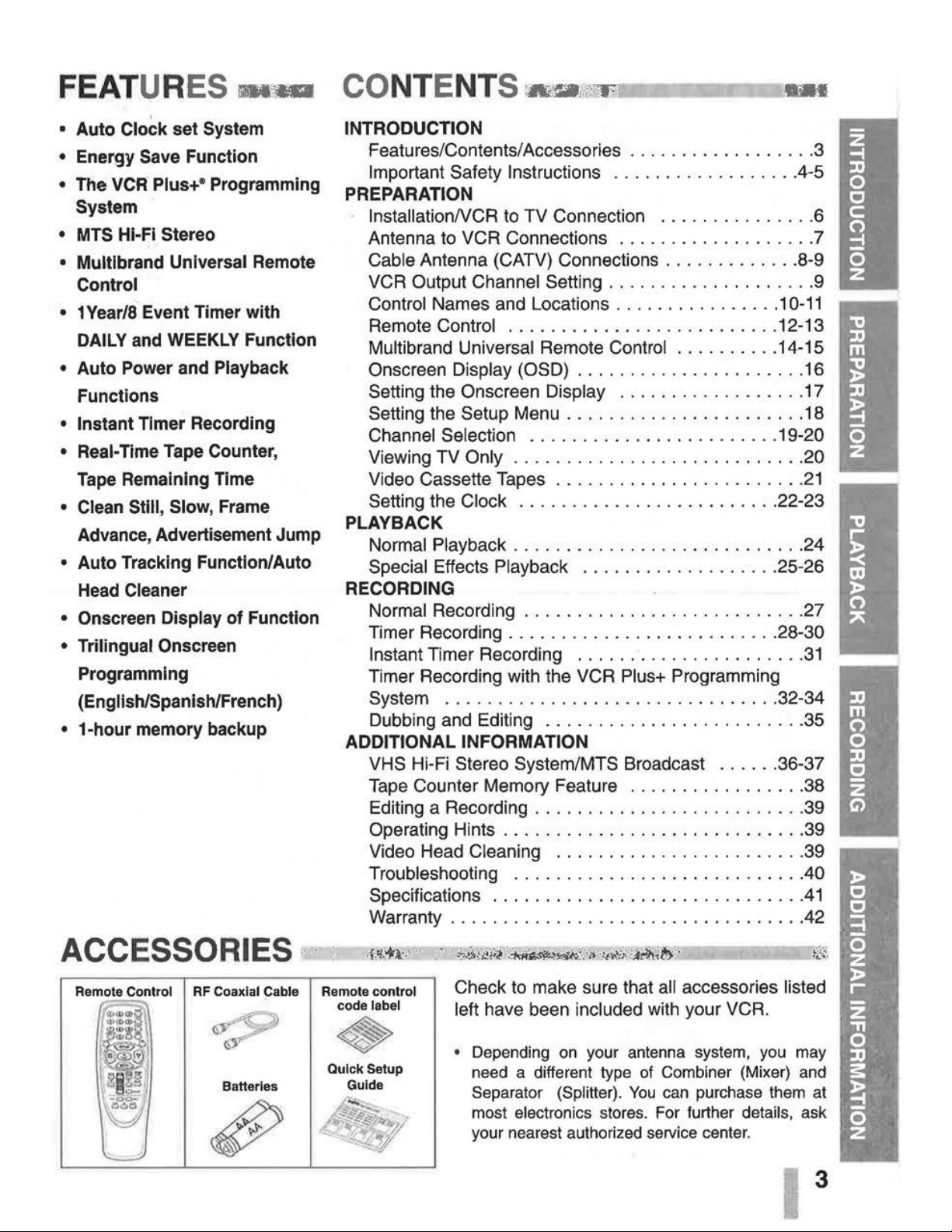
Check to make sure that all accessories listed
left
have been included with your VCR.
• Depending
on
your antenna system, you may
need a different type
of
Combiner (Mixer) and
Separator (Splitter).
You
can purchase them at
most
electronics stores. For further details, ask
your nearest authorized service center.
3
Page 4
IMPORTANT SAFETY INSTRUCTIONS-
Important safeguards for you and your new product
Your product has been manufactured and tested with your safety in mind. However, improper use can
result in potential electrical shock or fire hazards.
To
avoid defeating the safeguards that have been built
into your new product, please read and obseNe the
following safety points when installing and using your
new product, and save them for future reference.
ObseNing the simple precautions discussed
in
this section of the operating guide can help you get many
years of enjoyment and safe operation that are built into your new product.
1.
Read Instructions
All the safety and operating instructions should
be read before the product
is
operated.
2.
Follow Instructions
All operating and use instructions should be followed.
3.
Retain Instructions
The safety and operating instructions should be
retained for future reference.
4.
Heed Warnings
All warnings on the product and
in
the operat-
ing instructions should be adhered to.
5.
Cleaning
Unplug this product from the wall outlet before
cleaning. Do not use liquid cleaners or aerosol
cleaners. Use a damp cloth for cleaning.
6. Water and Moisture
Do not use this product near water - for example, near a bath tub, wash bowl, kitchen sink,
or
laundry tub, in a wet basement, or near a
swimming
pool.
7.
Accessories
Do not place this product on
an
unstable cart,
stand, tripod, bracket, or table. The product
may
fall, causing serious injury to a child or
adult, and serious damage to the product. Use
only with a cart, stand, tripod, bracket, or table
recommended by the manufacturer, or sold
with the product. Any mounting of the product
should
follow the manufacturer's instructions,
and should use a mounting accessory
recom-
mended by the manufacturer.
8.
Transporting Product
4
A product and cart combination should be
moved with care. Quick stops, excessive force,
and uneven surfaces may cause the product
and cart combination to overturn.
PORTABLE CART WARNING
9.
Attachments
Do not use attachments not recommended
by
the product manufacturer as they may cause
hazards.
10. Ventilation
Slots and openings
in
the cabinet are provided
for ventilation and to ensure reliable operation
of the product and to protect it from
overheating, and these openings must not be blocked or
covered. The openings should never be
blocked
by
placing the product on a bed, sofa,
rug, or other similar surface. This product
should not be placed
in
a built-in installation
such as a bookcase or rack unless proper ven-
tilation
is
provided or the manufacturer's
instructions have been adhered to.
11.
Power Sources
This product should be operated only from the
type of power source indicated on the marking
label. If you are not sure of the type of power
supply to your home,
consult your product dealer or local power company. For products
intended to operate from battery power, or
other sources, refer to the operating
instruc-
tions.
12.
Grounding or Polarization
This product
is
equipped with a polarized alternating-current line plug (a plug having one
blade wider than the other). This plug will fit
into the power
outlet only one
way.
This
is
a
safety feature.
If you are unable to insert the
plug
fully into the outlet, try reversing the plug.
If
the plug should still fail to fit, contact your
electrician to replace your obsolete
outlet.
Do
not defeat the safety purpose of the polarized
plug.
13. Power-Cord Protection
Power-supply cords should be routed so that
they are not
likely to
be
walked
on
or pinched
by items
placed upon or against them, paying
particular attention to cords at
plugs, convenience receptacles, and the point where they
exit from the product.
Page 5
IMPORTANT
SAFETY
INSTRUCTIONS
(Cont'd)~
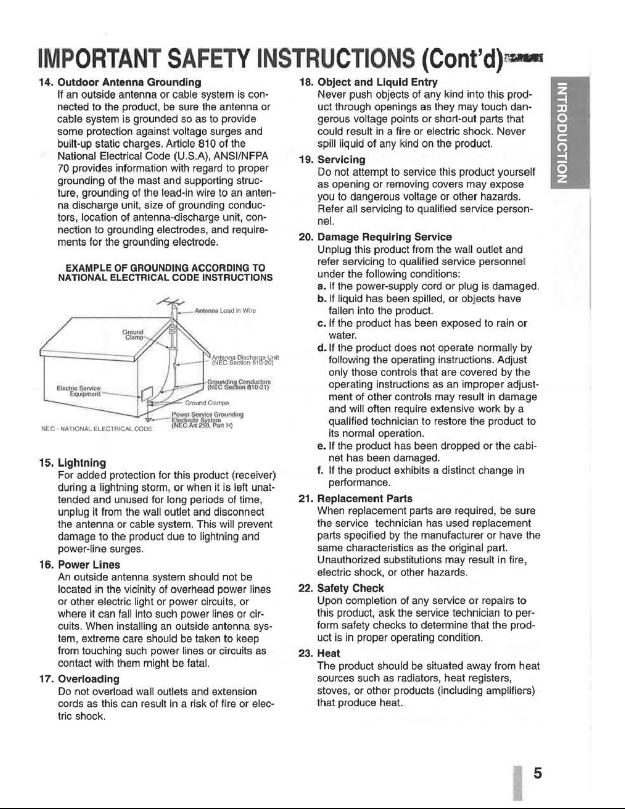
14. Outdoor Antenna Grounding
If
an
outside antenna or cable system
is
connected to the product, be sure the antenna or
cable system
is
grounded so as to provide
some protection against
voltage surges and
built-up static charges. Article 810 of the
National Electrical Code (U.S.A), ANSI/NFPA
70
provides information with regard to proper
grounding of the mast and supporting structure, grounding of the
lead-in wire to an antenna discharge unit, size of grounding conductors,
location of antenna-discharge unit, con-
nection to grounding
electrodes, and require-
ments for the grounding
electrode.
EXAMPLE OF GROUNDING ACCORDING TO
NATIONAL ELECTRICAL CODE INSTRUCTIONS
--~P,:J:~,~:""o>di"9
NEG
· NATIONAL ELECTRICAL
CODE
(N'!W M
~~~H)
15. Lightning
For added protection for this product (receiver)
during a
lightning storm, or when it
is
left unat-
tended and unused for
long periods of time,
unplug it from the wall outlet and disconnect
the antenna or
cable system. This will prevent
damage to the product due to
lightning and
power-line surges.
16. Power Lines
An
outside antenna system should not be
located
in
the vicinity of overhead power lines
or other electric light or power circuits, or
where it can
fall into such power lines or cir-
cuits. When
installing
an
outside antenna sys-
tem, extreme care
should be taken to keep
from touching such power
lines or circuits as
contact with them might be
fatal.
17. Overloading
Do
not overload wall outlets and extension
cords as this can
result
in
a risk of fire or elec-
tric shock.
18. Object and Liquid Entry
Never push objects of any kind into this product through openings
as
they may touch dan-
gerous
voltage points or short-out parts that
could result
in
a fire or electric shock. Never
spill liquid of any kind
on
the product.
19. Servicing
Do not attempt to service this product yourself
as opening or removing covers may expose
you to dangerous
voltage or other hazards.
Refer
all servicing to qualified service person-
nel.
20. Damage Requiring Service
Unplug this product from the wall outlet and
refer servicing to
qualified service personnel
under the following conditions:
a.
If
the power-supply cord or plug
is
damaged.
b.
If
liquid has been spilled, or objects have
fallen into the product.
c. If the product has been exposed to rain or
water.
d. If the product does not operate normally by
following the operating instructions. Adjust
only those controls that are covered by the
operating instructions as
an
improper adjust-
ment of other
controls may result
in
damage
and
will often require extensive work by a
qualified technician to restore the product to
its
normal operation.
e. If the product has been dropped or the cabi-
net has been damaged.
f.
If the product exhibits a distinct change in
performance.
21. Replacement Parts
When replacement parts are required, be sure
the service technician has used
replacement
parts specified
by
the manufacturer or have the
same characteristics as the
original part.
Unauthorized substitutions may
result
in
fire,
electric shock, or other hazards.
22. Safety Check
Upon completion of any service or repairs to
this product, ask the service technician to perform safety checks to determine that the product
is
in
proper operating condition.
23. Heat
The product should be situated away from heat
sources such as radiators, heat registers,
stoves, or other products
(including amplifiers)
that produce heat.
5
Page 6
INSTA
LL
ATI
ON:
Placing your VCR
on
the top of or under the TV receiver may result
in
interference appearing
on
the TV screen when the VCR
is
on.
If this occurs, move the VCR
to
a position alongside the
TV
receiver.
VCR
TO
TV CONNECTION·
-------
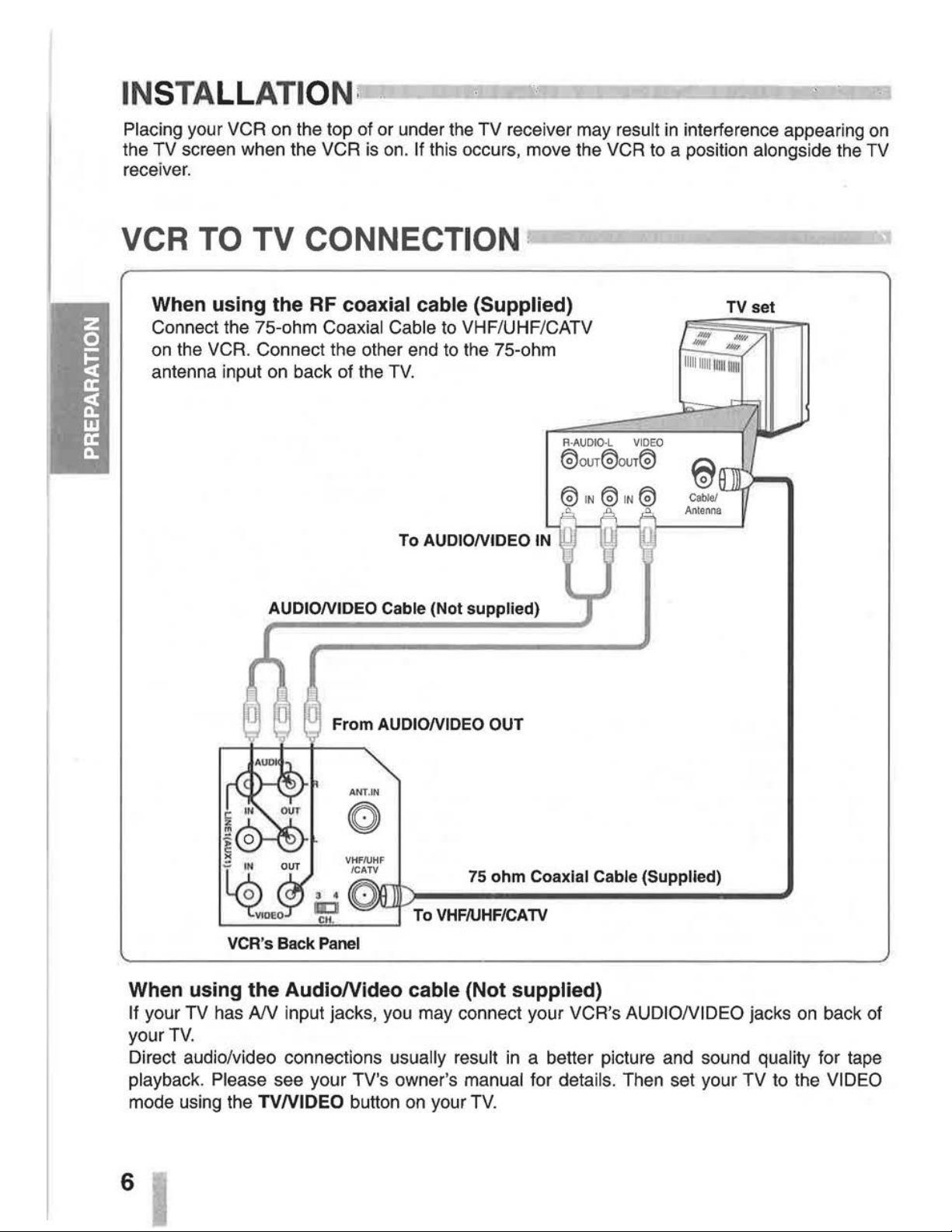
When
using
the RF coaxial cable (Supplied)
Connect the 75-ohm Coaxial Cable
to
VHF/UHF/CATV
on
the VCR. Connect the other end
to
the 75-ohm
antenna input
on
back of the
TV.
To AUDIONIDEO
IN
AUDIONIDEO Cable (Not supplied)
From
AUDIONIDEO OUT
75
ohm
Coaxial Cable (Supplied)
To
VHF/UHF/CATV
VCR's Back Panel
When using
the
AudioNideo
cable (Not supplied)
TV
set
If your TV has
AN
input jacks, you may connect your VCR's AUDIONIDEO jacks
on
back of
your
TV.
Direct audio/video connections usually result
in
a better picture and sound quality for tape
playback. Please see your TV's owner's manual for details. Then set your TV to the VIDEO
mode using the
TVNIDEO
button
on
your
TV.
6
Page 7
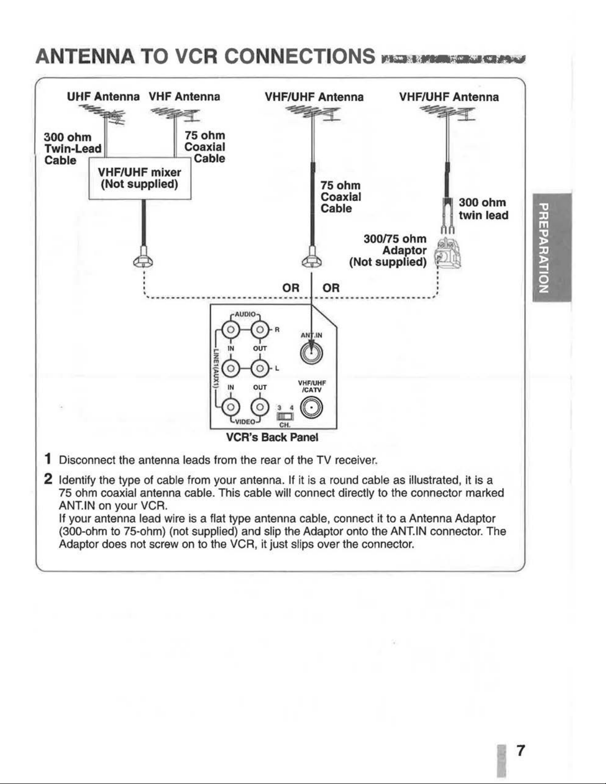
ANTENNA TO VCR CONNECTIONS
Maril~~-.a
...
mtF
Antenna VHF Antenna
VHF/UHF Antenna VHF/UHF Antenna
300
ohm
75
ohm
Twin-Lead Coaxial
Cable
,---•L--
---"----,
Cable
VHF/UHF mixer
(Not
supplied)
AR
C
IN
OUT
OR
75ohm
Coaxial
Cable
3oons
ohm
Adaptor
(Not supplied)
-----
-------·--··-·-···;
~
@-@L
~
VHF/UHF
~
iP
:.:
O
VCR's Back
Panel
1 Disconnect the antenna leads from the rear of the TV receiver.
'
.
300ohm
twin
lead
2 Identify the type of cable from your antenna. If it
is
a round cable as illustrated, it is a
75 ohm
coaxial antenna cable. This cable will connect directly to the connector marked
ANT.
IN
on
your VCR.
If your antenna lead wire
is
a flat type antenna cable, connect it to a Antenna Adaptor
(300-ohm to 75-ohm) (not supplied) and slip the Adaptor onto the
ANT.
IN
connector. The
Adaptor does not screw
on
to the VCR, it just slips over the connector.
7
Page 8
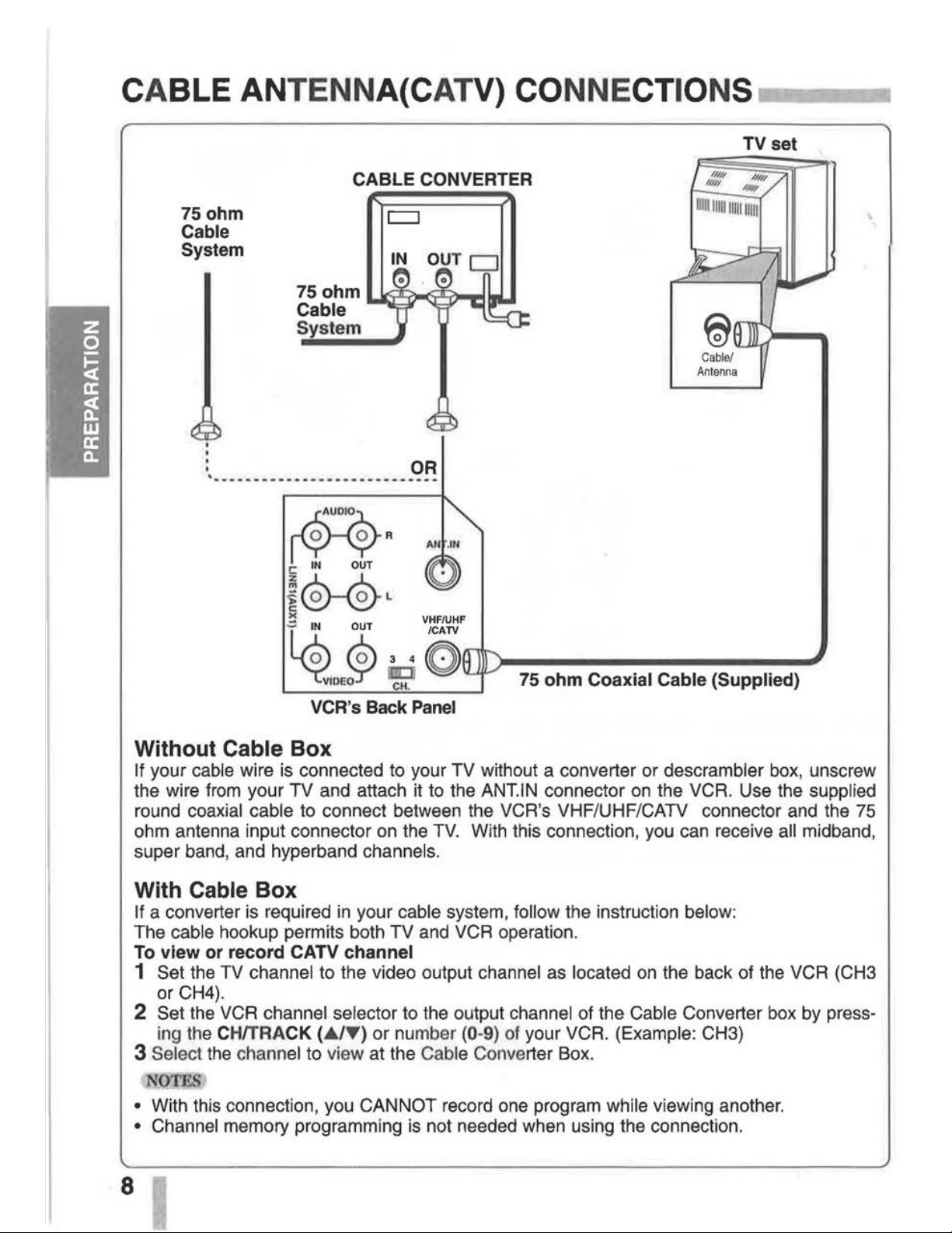
CABLE ANTENNA( CATV)
CONNECTIONS
..-----.~
75ohm
Cable
System
CABLE
CONVERTER
c:::J
75 ohm U
):ll:f
)oo(';Jl::f)-.1
Cable
System
~
I'Y.
'XR
C:
IN OUT
~0--@L
><
VHF/UHF
/CATV
TV
set
~~$
75 ohm Coaxial Cable (Supplied)
VCR's Back
Panel
Without Cable Box
If your cable wire is connected to your TV without a converter or descrambler
box,
unscrew
the wire from your TV and attach it to the
ANT.IN connector
on
the VCR. Use the supplied
round coaxial cable to connect between the VCR's VHF/UHF/CATV connector and the
75
ohm antenna input connector on the
TV.
With this connection, you can receive all midband,
super band, and hyperband
channels.
With Cable Box
If a converter is required
in
your cable system, follow the instruction below:
The cable hookup permits both TV and VCR operation.
To view or record CATV channel
1 Set the TV channel to the video output channel as located
on
the back of the VCR (CH3
or CH4).
2 Set the VCR channel selector to the output channel of the Cable Converter box by press-
ing the
CH/TRACK (
.A
lY) or
nu
mber (0-9)
of
your VCR. (Example: CH3)
3 Select the channel to view at the Cable Converter Box.
N
TES
• With this connection, you CANNOT record one program while viewing another.
• Channel memory programming
is
not needed when using the connection.
Page 9
CABL
ANTENNA(CATV)
CONNECTIONS
(Cont'd)
75
ohm
Cable System
TV set
2-way Splitter
'-r--T---.--
r'
(Not supplied)
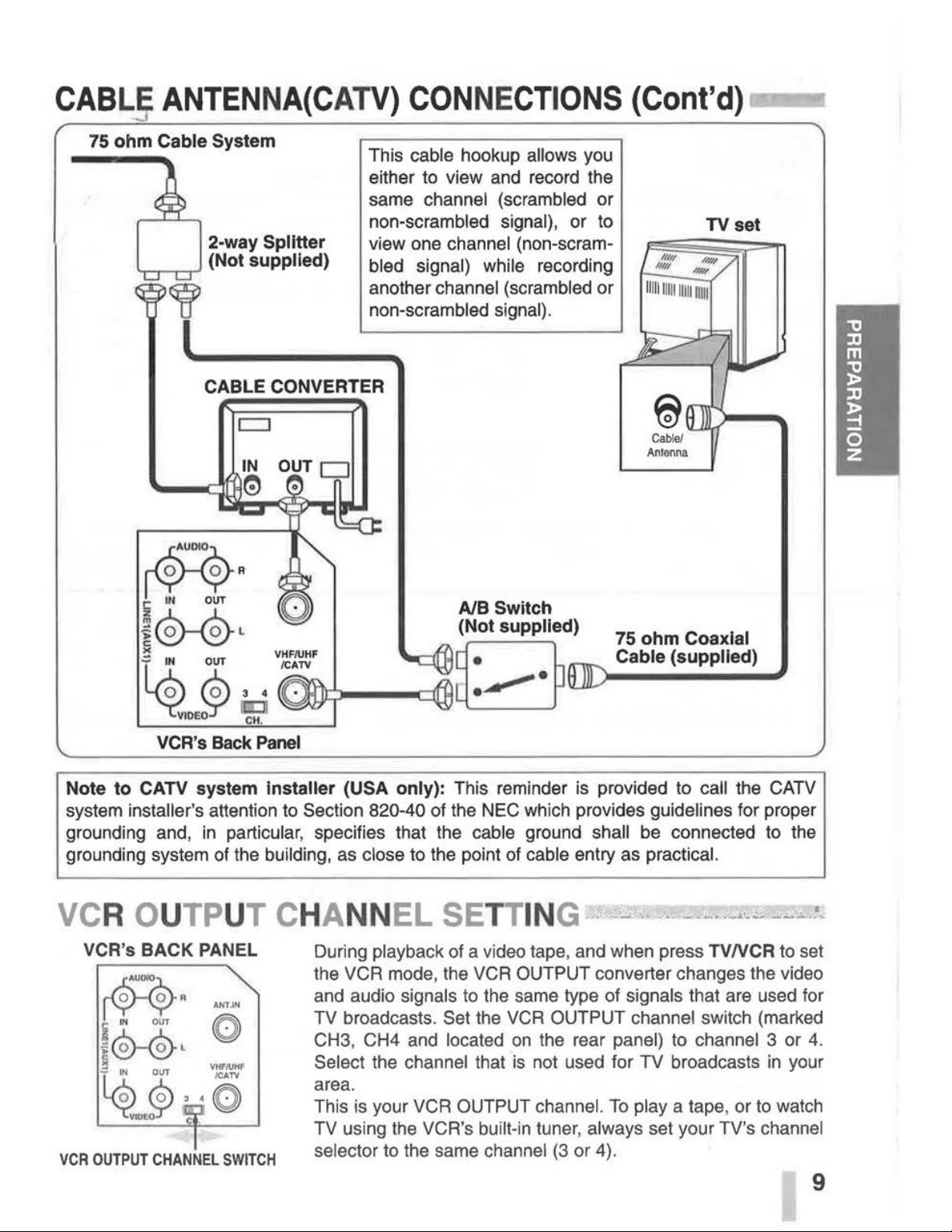
This cable hookup allows you
either to view
and
record the
same
channel (scrambled or
non-scrambled
signal), or to
view one
channel (non-scram-
bled signal) while
recording
another channel (scrambled or
non-scrambled signal).
CABLE CONVERTER
c::::J
VCR'S
Back
Panel
75
ohm
Coaxial
Cable (supplied)
Note
to
CATV system installer (USA only): This reminder
is
provided to call the
CATV
system installer's attention to Section 820-40 of the NEC which provides guidelines for proper
grounding and,
in
particular, specifies that the cable ground shall
be
connected to the
grounding system
of
the building,
as
close to the point
of
cable entry as practical.
VCR's BACK PANEL
~
fYY"
i
IN
OUT
~
®-®L
f~
~3
Y.~~
ANT
.IN
VHF/UHF
/CATV
·0
VCR
OUTPUT
CHANNEL
SWITCH
During playback of a video tape, and when press TV
NCR
to set
the VCR mode, the
VCR
OUTPUT converter changes the video
and audio
signals to the same type of signals that are used for
TV
broadcasts. Set the
VCR
OUTPUT channel switch (marked
CH3, CH4
and
located
on
the rear panel) to channel 3 or 4.
Select the channel that
is
not used for TV broadcasts
in
your
area.
This
is
your VCR OUTPUT channel.
To
play a tape, or to watch
TV
using
the
VCR's built-in tuner, always set your TV's channel
selector
to the same channel
(3
or 4).
9
Page 10
CO NTROL NAME S AND LOC
ATI
ONS
r!VIr.-.tJti\,:~~~~
I FRONT
~
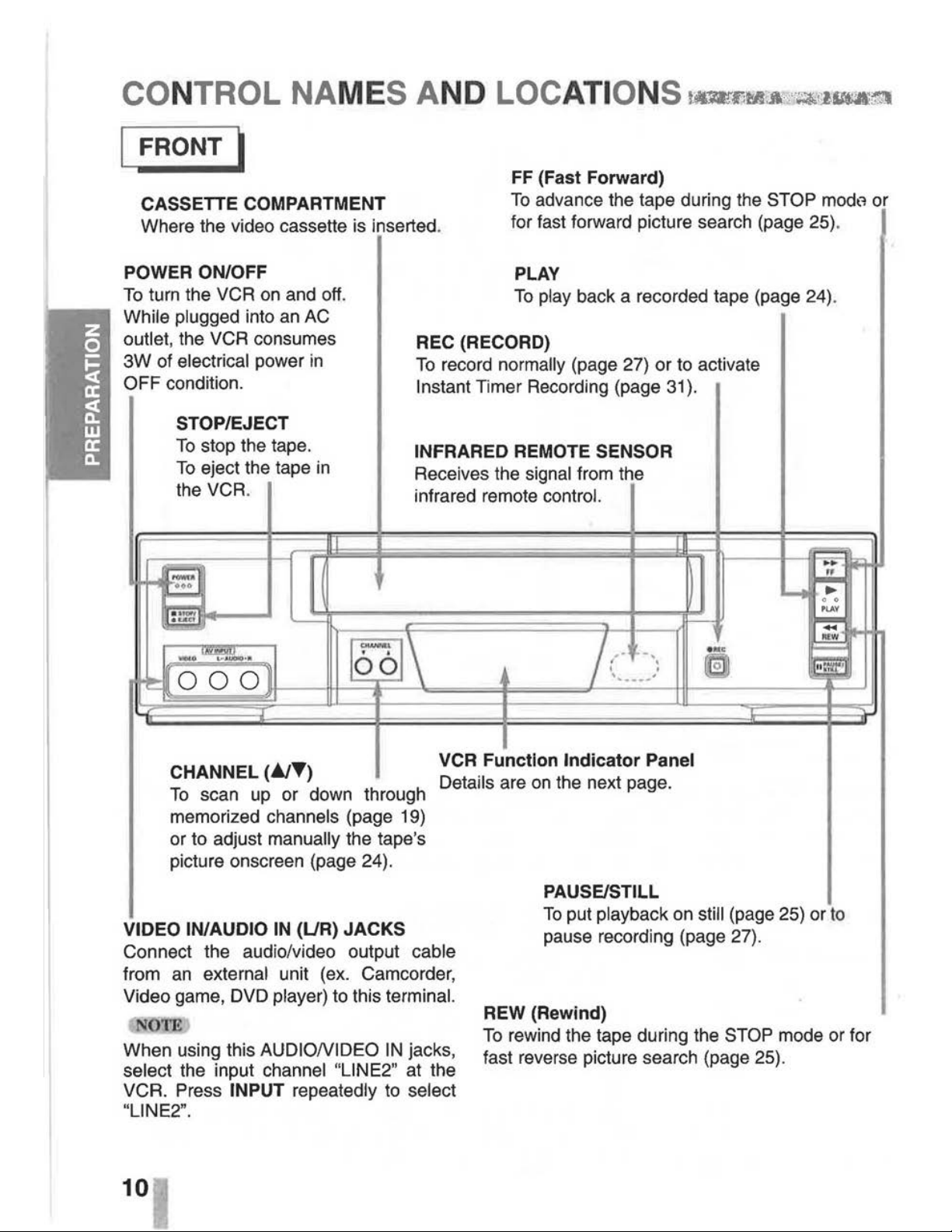
FF
(Fast Forward)
CASSETTE COMPARTMENT
Where the video cassette is inserted.
To
advance the tape during the STOP
modt1
or
POWER ON/OFF
To
turn the VCR on and
off.
While plugged into an AC
outlet,
the VCR consumes
3W
of electrical power
in
OFF condition.
STOP/EJECT
To
stop the tape.
To
eject the tape
in
the VCR.
~
-!.:.,
'----
for fast forward picture search (page 25).
PLAY
To
play back a recorded tape (page 24).
REC (RECORD)
To
record normally (page 27) or to activate
Instant Timer Recording (page
31
).
INFRARED REMOTE SENSOR
Receives the signal from the
infrared remote
control.
ll
1....!1
i""""'
....
~
....
0 0
P
LAY
~
m
------...
'"="'
~\
~--
/
-·
-
..
.
...
=
'llll!lll)~··
~
000
•"
...
·---
...
eJ
~
CHANNEL
(~T)
To
scan up or down through
memorized
channels (page 19)
or to adjust
manually the tape's
picture onscreen (page 24).
VCR
Function
Indicator
Panel
Details are on the next page.
VIDEO IN/AUDIO
IN
(UR)
JACKS
Connect the audio/video output cable
from
an
external unit (ex. Camcorder,
Video game, DVD
player) to this terminal.
NOTE
When using this AUDIONIDEO
IN
jacks,
select the input channel "LINE2" at the
VCR. Press
INPUT repeatedly to select
"LINE2".
10
PAUSE/STILL
To
put playback on still (page 25) or
to
pause recording (page 27).
REW (Rewmd)
To
rewind the tape during the STOP mode or for
fast reverse picture search (page 25).
Page 11

CONTROL NAMES AND LOCATIONS (Cont'd)
---.
~
ANTENNA INPUT CONNECTOR
I REAR I
Connect the VHF/UHF/CATV antenna to this terminal.
AUDIO OUT (UR) JACKS; Connect this terminal to the audio input terminal on an exter-
nal
unit (Audio System, TV/Monitor, Another VCR).
VIDEO OUT JACK; Connect this terminal to the video input terminal on
an
external unit
(TV/Monitor, Another VCR).
AUDIO
IN
(UR) JACKS; Connect the audio o'utput cable from an external unit (ex. Audio
system, TV/Monitor, DVD player, Another VCR) to this
terminal.
VIDEO
IN
JACK; Connect the video output cable from an external unit (ex. Audio system,
TV/Monitor,
DVD
player, Another VCR) to this terminal.
·
~
When using this AUDIONIDEO
IN
jacks, select the input channel "LINE1" at the VCR.
Press
INPUT
to
select "LINE1".
WARNING
:
Do
not
drop
the
tying
band
of
the
power
cord
into
the
unit.
Doing
so
might
cause a fire
or
an
electrical
shock.
VCR
OUTPUT
CHANNEL
SELECT
SWITC~
Set this switch to channel 3 or
4.
POWER CORD
Connect only to
an
AC
120V,
60Hz outlet.
VHF/UHF/CATV
ANTENNA
OUTPUT
CONNECTOR
Connect this terminal to the VHF or UHF
antenna terminals on the back of a TV .
• • • • • • • • • • • • • • • • • • • • • • • • • • • • • • • • • • • • • • • • • • • • • • • • • • • • • • • • • • • • • • • •
I INDICATOR PANEL I
Cassette indicator -
--...
Lights while a cassette is
inserted, and
flashes while
ejecting a cassette.
cror·····;,
· ·m··-
;~·
rfii
' !
•~e
'l(
Rec;~-
;,
-
Record
indicator-----/
vcR
L__~~-~:.
-~.
·-~~-~~~
j
~~~
TIMER indicator
P------
t---
---
".,..---AM
indicator
VCR
indicator----../
Use
TVNCR
on the remote control
to turn this indicator ON or OFF.
ON:
for playback, VCR programming
or watching
TV programs through the
VCR tuner
OFF: for watching
TV
programs
through
TV
tuner
Clock/Tape operation indicator
HI
-VCR
is turned on.
BYE-
VCR is turned off.
(PM is not displayed)
11
Page 12

REMOTECONTROL
-·
------------------~
The remote control
is
used for most of the operations and features of the VCR. Before proceed-
ing, put batteries
in
the remote and become familiar with the buttons. Use only type AA batter-
ies. The maximum operating distance
is
about
25
feet.
The
POWER,
PLAY,
PAUSE,
FF,
REW and
REC
buttons
on
the remote control unit perform the
same functions as the corresponding buttons
on
the VCR. The remaining buttons are
on
the
remote
control unit only .
12
....---------
NUMBER buttons
Use these buttons, numbered 0-9, to select a channel.
.----
TV NCR
To
view channels selected by the VCR tuner or by the
TV tuner (page
9,
27) .
.7""1'11T'i---
Ad
JUMP
To
fast forward picture search through
30
seconds of
recording (page 26).
~-.-
__
SP/SLP
Use to select recording speed (page 27) .
.---
ENTER (CLKICOUNT)
Accesses the onscreen menu (page 17).
Displays functions
on
the TV screen. Switches among
the
clock, tape counter and tape remaining modes on
the
display (page
16,
38).
VCR Plus+
To
display the program menu on the
TV
screen for the
VCR
Plus+ programming (page 34).
SLOW
For slow motion playback during PLAY mode (page 25).
CLEAR
Cancels a timer recording (page 30).
Resets tape counter to 0:00:00 (page 38).
VOL
(volume) (
+1-)
To
adjust TV volume.
'----VCR/CATV/TV
MODE
SELECTOR
Use to select operation mode (page 14).
~-.-
_________
• T
.....
~
ARROWS
Move up, down, left, right one row, column, or selection
(hold
to repeat) (page
17,
18).
Page 13
REMOTE CONTROL (Cont'd)
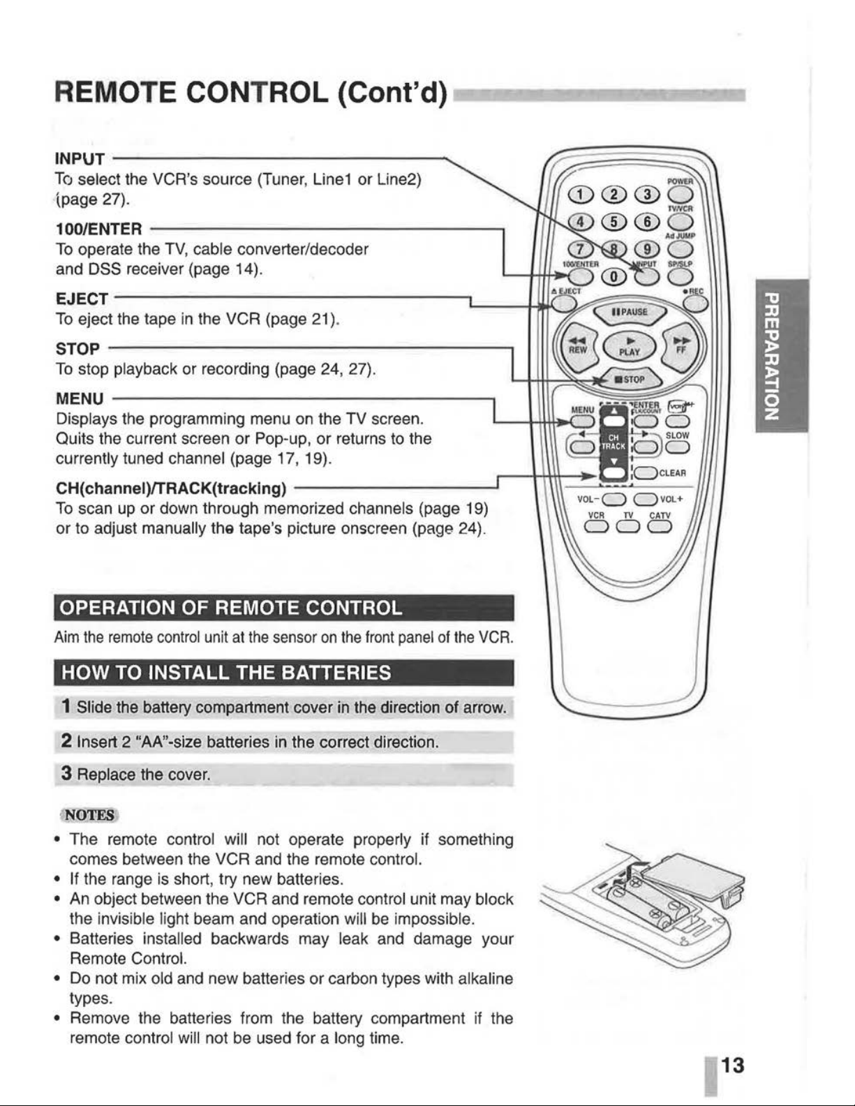
INPUT
--------------
........
To
select the VCR's source (Tuner,
Line1
or Line2)
(page 27).
100/ENTER
---------------.
To
operate the TV, cable converter/decoder
and
DSS receiver (page 14).
EJECT---------------------------L----U~~
~==~
To
eject the tape
in
the VCR (page
21
).
STOP
----
--
------------
--
---------.
To
stop playback or recording (page 24, 27).
MENU
-------------------------~
Displays the programming menu
on
the TV screen.
~----FcS
·
E5
Quits the current screen or Pop-up, or returns to the b
0
currently tuned channel (page 17, 19).
r----+1+\\-
:ocLEAR
CH(channei)/TRACK(tracking)
-----------------'
To
scan
up
or down through memorized channels (page 19)
or to adjust manually
the tape's picture onscreen (page 24).
OPERATION
OF
REMOTE CONTROL
Aim
the
remote
control
unit
at
the
sensor
on
the
front
panel
of
the
VCR
.
HOW
TO
INSTALL THE BATTERIES
1 Slide the battery compartment cover
in
the direction
of
arrow.
2 Insert 2 "AA"-size batteries
in
the correct direction.
3 Replace the cover.
·NOTES
• The remote control will not operate properly if something
comes between the VCR and the remote control.
• If the range
is
short, try new batteries.
•
An
object between the VCR and remote control unit may block
the invisible light beam and operation will
be
impossible.
• Batteries installed backwards may leak and damage your
Remote Control.
•
Do
not mix old and new batteries or carbon types with alkaline
types.
• Remove the batteries from the battery compartment
if
the
remote control will not
be
used for a long time.
VOL-C)
C)VOL+
13
Page 14

MULTIBRAND UNIVERSAL REMOTE CONTROL;
IMPORTANT NOTE: If
the batteries in the
remote control are
replaced, the codes for
the
TV
, CATV converter/decoder and DSS
receiver must be reset.
Write your code numbers
below for future
refer-
ence.
TV:
_ _ _ _
CATV:, ___
_
DSS:
__
_ _
Place the supplied label
on
the back of the remote
control.
14
Your remote control
is
capable of operating your VCR as well as
limited functions of certain televisions, cable (CATV)
converters/decorders and
DSS (Digital Satellite System)
receivers.
In
addition, this remote control is programmed with the
remote control codes of many popular brands, listed
on
the nex
i\
page.
Follow the instructions below to set the appropriate code for your
TV.
SETTING THE REMOTE CONTROL CODE
1
In
the chart
on
the next page, find the code corresponding to
your brand.
2 While holding down the
TV
or
CATV corresponding to your
device, enter the 2-digit code using the number
(0-9) (see
the next page).
The remote
control
is
now set
to
your device.
TV MODE OPERATION
To
use the remote control with your TV, press TV.
You
can use
POWER, 1 00/ENTER, INPUT, CH/TRACK (A/'f'), VOL
(+I-)
and number (0-9) buttons to control the
TV.
CATV MODE OPERATION
To
use the remote control with your cable (CATV)converter/
decoder or
DSS
(Digital Satellite System) receivers, press
CATV.
You
can use POWER, 100/ENTER, INPUT,
CHITRACK
(A/'f')
and number (0-9) buttons
to
control the CATV convert-
er/decoder or DSS receiver.
iNO'IE&)
• Only remote-controlled products can be operated using this
remote
control. (Refer
to
the instruction manuals for your
TV,
CATV converter/decoder or
DSS
receiver instruction manual
for more details.)
•
There may be some
TV,
CATV converter/decoder or
DSS
receiver models that cannot
be
operated with this remote con-
trol.
If
this
is
the case, use the original remote control supplied
with your equipment.
• Cable companies may charge
an
extra monthly fee to activate
the remote
control feature of a rented CATV
converter/decoder.
If
this
is
the case, this remote control will
not operate the cable converter/decoder unless such arrangements are made with the cable company.
Page 15

MULTIBRAND
UNIVERSAL
REMOTE
CONTROL
(Cont'd) -,,
·
MUL TIBRAND REMOTE CONTROL CODES BY BRAND
TV Cable
converter/decoder
Brands
Code
Brands
Code
ADMIRAL
05, 10, 13
NOVA VISION
19
32
EMERSON
17
NSC
20,39
FISHER
03
OAK
04,
34
GE
07
OAK SIGNA
04,34
GOLDSTAR
01
PANASONIC 08,
19,2
1
HITACHI
02
PHILIPS
14 31, 36,
40
JVC
15
PIONEER
06,23
MAGNA VOX
08
PULSER
05,11
MATSUSHITA
12,
18
QUEST
06,23
MITSUBlSHl
14
RADIO SHACK
00,29
PANASONIC
12
18
RCA
06
, 19,21
QUASAR
12
18
REALISTIC
00
29
RCA
06
RECOTON 00,29
SAMSUNG
16
REGAL
12,17, 37
SANYO
03
REMBRANDT 00,
11,29
SHARP
00, 13
SAMSUNG 06,
11
22
SONY
11
SCIENTIFIC ATLANTA
1
9,25
,32
TECHNOLACE
05
SH
ERITECH
44
TOSHIBA
04
SIGNAL
43
ZENI
TH
09, 10
SLMARX
06,11.
22
Cable
converter/decoder
SPRUC
ER
08
, 19,21
Brands
Code
STARGATE
OS. 11
22
ARCHER
00,01,06.29
SYLVANIA
38
,39
CABLE CINEMA
01,32
TEKNIKA
30
CABLETENNA
01.32
TELECAPTION
26
CABLEVIEW
01
32
TELEVIEW
2
0,22
39
CENTURY
00
29
TEXSCAN 38,
39
CITIZEN
00,24,29
TOCOM
01, 07
, 10,
11
CURTIS
19,25,32
UNIKA
00, 11
, 29
DIAMOND
01,32
UNIVERSAL
00,24,27,29
EAGLE
15,20,
36,40,41
VI
DEO
WAY
02, 03,
14
EXPLORER
19,32
VIEWSTAR
15
20
36,40,41
GC ELECTRONICS
00,11,29
ZENITH
02, 03,
14
GEMINI
05
DSS receiver
GENERAL
ELECTRIC
01,18
Brands
Code
GENERAL
INSTRUMENT
01,05,07,09,
16,28,33,65
DRAKE
77
GERRARD
00,29
HITACHI
70
75
HAMLIN
12, 17, 37
HUGHES
70
75
HITACHI
13
MAGNAVOX
78
79
JASCO
05
OPTIMUS
78,
79
JERROLD
01,05,07,09,
16,28,33
65
PANASONIC 73
MACOM
13
PRIMESTAA
76
MAESTRO
30
PRO SCAN
71
MAGNA
VOX
43
RCA
71
MATSUSHITA
08. 19,
21
SONY
72
NEC 20,39 TOSHIBA
74
NEXT LEVEL
01,05,07,09
, 16,28,33,
65
UNIDEN
78,
79
15
Page 16

ONSCREEN DISPLAY (OSD)
...
!t=-a~-.-ii1161~:m
PREPARATION
•
Turn on the power of both the VCR and TV.
•
Be
sure the TV is set to the VCR Output Channel (CH 3 or 4).
•
If
a direct VIDEO/AUDIO connection is made between the
VCR and the
TV,
set the TV's source selector to VIDEO.
ONSCREEN FUNCTION DISPLAYS
Some of these functions will
be
displayed every time the VCR
is
operated .
.----------
FUNCTION DISPLAY
PLA
Y
SP
Indicates the function
in
progress .
.------
HI-FI DISPLAY
Indicates
when
this unit
are
playing back
tape
recorded
with
HI-Fl.
CHANNEL DISPLAY
Indicates
the selected channel (or
LINE1
, LINE2).
STEREO/SAP DISPLAY (MONO
is
not displayed)
Shows the type of audio signal received
by
the VCR tuner.
1-----
-
+-
TAPE SPEED DISPLAY
JUL
S,THU
Shows the current tape speed.
CLOCK/COUNT/REMAIN DISPLAY
Shows
the current time, the tape counter and remaining time
on
the tape.
'--------
DATE
DISPLAY
Shows
the current date. (Month/Day/Day of the week format)
Each press of the ENTER changes the
TV
screen in the follow-
ing sequence.
STOP
CH
4
SP
STEREO
JUL
5.
THU
2:15PM
REM
1:58
N(i)TES
• The function displays can
be
seen displayed
on
the TV screen
for 5 seconds.
• The clock (or tape counter, tape remaining) mode will continue
until you press ENTER.
• The tape counter and the remaining tape length indicator
appear only when a cassette is inserted. Also, the remaining
tape length indicator appears after any tape operation.
Page 17

SETTING THE ONSCREEN DISPLAY
MAIN MENU
The
SETUP,
clock setting, and timer recordings are accessed
conveniently with Onscreen Menu Displays that lead you
through each step. The
following pages describe the Onscreen
selections
to
be set.
PREPARATION
• Turn
on
the power of both the
VCR
and TV.
•
Be
sure the TV
is
set to the VCR Output Channel
(CH
3 or 4).
•
If
a direct VIDEO/AUDIO connection is made between the
VCR and the TV, set the TV's source selector to
VIDEO.
MENU SELECTION
Your
VCR allows remote control adjustment of several features.
1 Press MENU and the MAIN menu will appear.
2 Select the desired menu with the
J;.
or
~
button and then
press
ENTER .
•
11j@Jtli
:wt1JI
II61;
\W
DAY
: I
MON
YEAR : 2001
TIM[ : 12:
00
AM
AUTO
CLOCK
SET : ON
DAYLIGHT
SAVING:
AUTO
TIME
ZONE:
AUTO
DD
SELECT
CCI
ADJUST
TO
EXIT
PRESS
l!ml!l
fril
'!§JfAtM;•
DAY
START
:
STOP
CHANNEL:
S
PEED
:
REPEAT
:
DD
SELECT
CCI
ADJUST
TO
EXIT
PRESS
l!ml!l
CLOCK SET (page 22-23)
PROGRAM (page 28-30)
CLOCK
-----t-'
PROGRAM--
-I--'
~
TUNI
NG---I~~
~
~
SETUP---I--t
l·lliieli:t.Jd@i#l•11
TUNING
BAND:
TV
CH. ADD/DEL: CH. 2
ADD
SOURCE
SELECT:
TUNER
DD
SELECT
CCI
ADJUST
TUNING (page 19-20)
DD
SELECT
miDll
ENTER
TO
EXIT
PRESS
lml1!l
TO
EXIT
PRESS
l!ml!l
.
lijiiiJIIi~i
!li'W
LANGUAGE
SELECT:
ENGLISH
AUDIO
MODE:
HI-FI
BROADCASTTYPE:
STEREO
AUDIO
OUTPUT:
STEREO
CHANNEL
MAPPING
DD
SELECT
CCI
ADJUST
TO
EXIT
PRESS
l!ml!l
· N0'FE
SETUP (page 18)
• The onscreens can
be
seen displayed for 3 minutes.
17
Page 18

SETTING THE SETUP MENU
'
!::UII~lltiii!!I!I::::J:~~~
MAIN MENU
~CLOCK
mJ
PROGRAM
~TUNING
•
SETUP
Dll
SELECT
l!llml
ENTER
TO
EXIT
PRESS
Im!l!J
SETUP MENU
"llll!ltlllol>i•
011•
LANGUAGE
SELECT:
ENGLISH
AUDIO
MODE
:
HI-FI
BROADCASTTYPE:
STEREO
AUDIO
OUTPUT:
STEREO
CHANNEL
MAPPING
Dll
SELECT
CICI
ADJUST
TO
EXIT
PRESS
tmml
Press
_.
or
~
to choose a
desired item on the
SETUP menu. Then press
...,..
or
..,..
to choose a
desired setting.
18
FUNCTION
OSD
\
The onscreen display of this VCR can be turned on or off.
The
FUNCTION OSD is switched between
ON
and OFF by \
pressing
<41111
or
..,..
.
LANGUAGE
SELECT
The onscreen programming of this VCR can display
in
either
English, Spanish, or French.
The LANGUAGE
SELECT is switched among ENGLISH,
SPANISH
and FRENCH by pressing
.....
or
......
AUDIO MODE DISPLAY
The
VCR
has
two
separate audio playback systems, the hi
gh
qual
-
Ity
VHS Hi-
FI
system and standard NORMAL mono sys
tem. The
same audio
is
generally recorded
on
both
systems. The
VHS Hi-Fi
system
plays
on
separate (left and
righ
t) channels, and the
NOR
-
MAL system plays monaural sound.
The nor
mal
track
is alw
ays
played
so
the cassette can be pla
yed
on a VCR
that does not
have
VHS Hi-F
i.
The AUDIO MODE is switched between HI-FI and NORMAL
by
pressing
<41111
or
..,..
.
BROADCAST TYPE DISPLAY (STEREO/SAP/MONO)
Multichannel Television Sound (MTS) carries stereo and/or
Second Audio Program (SAP) bilingual signals. Set this display
to
the desired position when both MTS stereo and SAP signals
are rece
iv
ed. When only one of the MTS signal is receive d, the
VCR automatically selects the corresponding receiving mode
(Stereo or SAP) regardless of the selected position.
For normal opera
tion
, the display should
be
in
the
STEREO
pos
i-
tion. The
VCR
will then record a STEREO program when available,
a
nd
record a mono program
IF
the program NOT
IN
STEREO.
The BROADCAST TYPE is switched among STEREO,
SAP,
and MONO by pressing
...,..
or
..,..
.
• For weak STEREO and/or SAP broadcasting, changing the
display to mono may give cle arer sound.
AUDIO OUTPUT DISPLAY (STEREO/LEFT/RIGHT)
Used during playback (when AUDIO MODE display (Hl-FI/NOR-
MAL)
Is
in
HI-FI position] for selecting the audio output signals
from
the AUDIO OUT terminals (L
ch
and R
ch), and
VHF
/UHF/
CATV
.
This display setting should
normally be lett
In
the stereo position,
so that when a stereo tape is played, the stereo sound
will be
heard through the
left and right channels. If a mono tape is
played a
nd
the
audio output is set
to
stereo, the same mono
sound
will be heard from both left and right channels.
The
AUDIO OUTPUT is switched among STEREO, LEFT, and
RIGHT by pressing
.....
or
..,..
.
CHANNEL MAPPING
Details are
on
the 33 page.
Page 19

CHANNEL SELECTION
r-r----~~~------.
~CLOCK
a
PROGRAM
TUNING
~
SETUP
liD SELECT
mimi
ENTER
TO
EXIT PRE
SS
l!lml
TUNING
BAND:
TV
CH
ADD/DEL:
CH 2 ADD
SOURCE
SELECT:
TUNER
1111
SELECT
I:ICI
ADJUST
TO
EXIT
PRESS
l!m!!l
AUTO
CHANNEL
SET
PROCEEDING
CHANNEL
13
TO
EXIT
PRESS
l!lill!l
AUTO
CHANNEL
SET
CH, ADD/DEL: CH 2 ADD
SOURCE
SELECT:
TUNER
1111
SELECT
I:ICI
ADJUST
TO
EXIT
PRESS
l!§ll!l
This VCR is equipped with a frequency synthesized tunei capa-
ble of receiving
up
to
181
channels. These include VHF chan-
nels 2-13, UHF channels 14-69 and CATV channels 1-125.
PREPARATION
• Connect the VCR to the desired type of antenna or cable TV
system, as shown
in
ANTENNA TO VCR CONNECTIONS and
CABLE ANTENNA (CATV)
CONNECTION (pages 7-9).
• Switch
on
the power to the
VCR
and
TV.
• Set the TV
to
the match the VCR output channel
(CH
3 or
4).
AUTO CHANNEL PROGRAMMING
1 Press MENU and the MAIN menu will appear.
2 Press
.A
or
'Y
to select the TUNING menu, then press
ENTER. The TUNING menu will appear.
3
Press-.
to choose the SOURCE SELECT item, then press
~
or
....
to select TUNER.
Press
~
or
..,.
repeatedly to switch among TUNER,
LINE1
and
LINE2.
4 Press
.A
or
'Y
to choose the AUTO CHANNEL SET item,
then press
~
or
..,.
to set the channel.
The tuner will automatically cycle through all available channels
in
the area and place them
in
the tuner's memory.
5 After the AUTO CHANNEL SET PROCEEDING is complete,
make sure the
TUNING BAND is set appropriately (TV or
CATV) by pressing
.A
or
'Y
and choosing the correct TUNING
BAND (TV or CATV)
by
pressing~
or
....
using the TUNING
menu.
• Remember, TV
is
for the air antenna reception, CATV is for
cable or wireless cable connection.
6 Press MENU to return
to
the TV screen.
Use
CHfTRACK
(~'Y)
or
CHANNEL (.&/'Y)
on
the front panel
to
cycle the VCR through the channels
in
memory.
19
Page 20

CHANNEL
SELECTION (Cont'd)
MAIN MENU
~CLOCK
[t;i1j
PROGRAM
TUNING
~
S
ETUP
1111
SELECT
mimi E
NTE
R
TO EX
IT
PRE
SS
lmll!l
TUNING MENU
AUTO
CHANNEL
SET
TUNING
BAND:
TV
l tf#M!
Ul•tJtl
MtliW¥lU!W
SOURCE
SELECT: TUNER
~ADD/DELETE
1111
SELECT
I:ICI
ADJUST
TO
EXIT
PRESS
1§111
TO ADD OR ERASE CHANNELS FROM MEMORV,
This feature allows you to add or erase channels
from
memory
manually.
1 Press MENU and the MAIN menu will appear.
2 Press _. or
~
to select the TUNING menu, then press
ENTER. The TUNING menu will appear.
3
Press~
to choose the CH. ADD/DEL item.
Press~
or..,.. to
select a channel to add or erase.
4 Press ENTER to add or erase the channel.
Repeat steps 3 and 4
to
add or erase channels.
5 Press MENU to return to the TV screen.
VI
EW
IN
G
TV
ON
LY
---,
--~~~---~---,
Switch on the TV and set it to the
channel that you wish to watch.
0
Set POWER to OFF.
20
You
don't need to disconnect the VCR from the TV
to
watch
TV
separately. When the VCR's power
is
OFF,
or when the VCR's
power
is
ON
and
the TVNCR selector
is
set to
TV,
the TV will
operate as if it were connected directly to the antenna or cable.
~
NO'.J$$
)
• The power cord must be plugged into
an
AC
outlet.
•
To
view or record cable TV programs with the
VCR,
the VCR's
TUNING BAND item must be set to CATV (TUNING menu).
•
Do
not place the VCR directly
on
top of the TV. This may
cause interference
in
the picture and sound (of the VCR) dur-
ing the recording or
playback mode.
If
this interference
occurs,
locate the VCR away from the TV.
Page 21

VIDEO CASSETTE
TAPES
...------~-~--~
./
SAFETY
TAB
To
prevent accidental erasure, remove the tab after
recording.
To
record again cover the
hole with vinyl tape.
a
This VCR will operate with any video cassette which
has
the
IVHSl
mark. The table below shows the recording/playback
time of
VHS cassettes when they are used
in
the
SP,
LP
and
SLP speeds. (LP speed
is
for playback only.)
~
~
SPEED
1-60
T-1LU
T-160
SP MODE
60
mins.
120 mins . 160 mins.
LP
MODE 120 mins.
240 mins. 320 mins.
SLP MODE 180 mins. 360 mins. 480 mins.
WHEN HANDLING VIDEO CASSETTES
• Do not expose video cassettes to extreme heat, high humidity,
or strong magnetic fields.
•
Do
not tamper with the cassette mechanism.
•
Do
not touch the tape with your fingers.
• Always store
an
unused cassette
in
its case.
LOADING
Hold the cassette with the arrow side
up
(top). Insert the
cassette
gently into the slot
in
the direction of the arrow (on the
cassette)
until the loading mechanism automatically pulls the
cassette into the unit. Make certain that the cassette
is
inserted
correctly.
• If
the cassette is not loaded correctly, the VCR will eject the
cassette
automatically after approximately 3 seconds.
UNLOADING
Press STOP/EJECT twice or press EJECT
on
the remote control. The cassette will be ejected automatically. After the cassette
is
visible
in
the tape slot, pull it out
to
remove
it.
• Unloading the cassette
is
possible only when the power cord
is connected to the
wall outlet.
•
The cassette can
be
ejected when STOP/EJECT is pressed,
even if the VCR's power is
OFF.
21
Page 22

SETT
IN
G THE CLOCKr,
~============--~~-
MAIN MENU
II
CLOCK
[i!j]
PROGRAM
~TUNING
~SETUP
Dll
SELECT
mmi!
ENTER
TO
EXIT
PRESS
I!Iml
CLOCK
MENU
MONTH: JANUARY
DAY
I
MON
YEAR : 2001
TIME : 12: 00
AM
8511-Mhl.tw!Ww
TIME
ZONE:
AUTO
Dll
SELECT
I:ICI
ADJUST
TO
EXIT
PRESS
I!Iml
~
MONTH:
JANUARY
~
DAY
: I
MON
YEAR : 2001
TIME
:12:00
AM
AUTO
CLOCK
SET : ON
i.MiW~{.
iAY!!IMV
.
Ww
Dll
SELECT
I:ICI
ADJUST
TO
EXIT
PRESS
I!Iml
NOTE
There are cases that
TV
station does
not
send
or
send wrong date and/or
time information and
VCR
set the incorrect time
accordingly.
In this case we recommend
that you set the
clock
manually.
22
Things
to
know
before
starting
\
• The clock uses the 12-hour system. (Be sure to set
AM
and
PM
correctly.)
• The buttons for setting the clock are on the remote control.
•
An illogical date will not be accepted (for example:
February 30).
•
The initial Clock Setting is JANUARY
1,
2001, 12:00 AM.
PREPARATION
• Turn
on
the power of both the VCR and TV.
•
Be
sure the TV
is
set to the VCR Output Channel (CH 3 or 4).
•
If
a direct VIDEO/AUDIO connection is made between the
VCR and the
TV,
set the TV's source selector to VIDEO.
The VCR gives you
two
ways to set the time and date:
the
Auto
Clock Feature or manually. The Auto Clock Feature enables
the
VCR
to set up the clock when the VCR is turned
off.
AUTO CLOCK SET
1 Press MENU and the MAIN menu will appear.
2 Press
.._
or~
to choose the CLOCK menu.
Press ENTER and the
CLOCK menu will appear.
3 Press T to choose the AUTO CLOCK SET item.
Press
~
or
..,..
to choose ON.
The Auto Clock Set feature
is
set to
ON
at the factory.
In
the
ON
setting, the VCR looks for a channel carrying XDS (Extended
Data Services) information. XDS updates the clock using the
Coordinated Universal Time.
4 Press T to choose the DAYLIGHT SAVING item.
Press
~
or
..,..
to choose AUTO,
ON
or
OFF.
If you choose AUTO, the VCR sets the clock using the
DST
infor-
mation broadcast
in
the signal (channel).
If
you choose ON, the VCR sets the clock when the Daylight
Saving Time
is
started and ended.
5
Press
~to
choose
the
TIME
ZONE
item
.
Press
<0111
or
..,..
to
choose
the
correct
time
zone
(AUTO,
ESTERN,
CENTRAL,
MOUNTAIN,
PACIFIC,
ALASKA
or
HAWAII)
.
If "AUTO"
is selected
as
the time zone, the VCR sets
the
clock
using the first Coordinated Universal Time information
it
finds
in
a broadcast signal.
6 Press MENU when finished.
7 Turn off the VCR and the auto clock setting works.
Page 23

SETTING THE CLOCK (Cont'd)
CLOCK
PROGRAM
TUNING
SETUP
liD
SE:LECT
l!llllll
EIJlEH
TO
E:XIT
PRESS
l!l!ml
CLOCK
MENU
IAI•IIII
MlJ
lli61;\W
DAY
' l
1.1014
YcAR
2ll01
TIME
: 12:
00
AM
AU-TO
CLOCK
SET : ON
DAYLIGHT
SAVING:AUTO
TIME
ZOIIE
;
AUTO
liD SELECT
I:ICI
ADJUST
TO
EXIT
PRESS
l!lml
tW;YIH
Jli..)
"._
V
~R
•
200
1
TIME : 12 : 00
AM
AUTO
ClOCK
SET
:
OFF
DAYLIGHT
SAVING:
AUTO
TIME lOII
E!
AUTO
liD
SELECT
I:ICI
ADJUST
TO
EXIT
PRESS
l!lml
1.1014TH
JUL\1
DAY
·
~
ru
'Y.\i'!"i2"h
IU
AUTOCLOCKSH· OFF
DAYLIGHT
SAVUIG:AUTO
Tiloll
o
lOIIE
:
AUTO
liD SElECT
I:ICI
ADJUST
TO
EXIT
PRESS
lm:D
MONTH:
JULY
DAY
5
THU
y l
mr~8~q~M~hBn
Tllo\E
ZOtiE
AUTO
liD
SELECT
I:ICI
ADJUST
TO
EXIT
PRESS
l!lll1!l
MONTH, JULY
DAY
: 5
THU
YEAR : 2001
TIME
2:
15
AM
~~~
~
am•"
liD
SELECT
I:ICI
ADJUST
TO
EXIT
PRESS
~mill
MANUAL CLOCK SET
Example:
July
5,
2001
; 2:15 AM
1 Press MENU and the MAIN menu will appear.
2 Press • or T to choose the CLOCK menu.
Press ENTER and the
CLOCK menu will appear.
3 Press • or..,.. to choose the month.
4 Press T to choose the
DAY
item.
Press
• or
..,..
to choose the day.
The day of the week
will display automatically.
5 Press T to choose the YEAR item.
Press
• or
..,..
to choose the year.
6 Press T to choose the TIME item.
Press
• or
..,..
to choose the time.
7 Press T to choose the DAYLIGHT SAVING item. Press •
or
..,..
to choose the ON or
OFF.
8 Press MENU when finished.
NOTE
The "AUTO CLOCK SET" must set to "OFF
".
If
set to "ON",
an
incorrect date and/or time will
be
entered again
when the
VCR
is
turned off.
23
Page 24

NORMAL PLAYBACK
..------------
24
PREPARATION
• Turn
on
the
TV.
\
•
Be
sure the TV is set
to
the
VCR
Output Channel (CH 3
or 4 ).
\
• If
a direct VIDEO/AUDIO connection is made between
the
VCR and the
TV,
set the TV's source selector
to
VIDEO.
NORMAL PLAYBACK
1 Insert a prerecorded video cassette.
The
<J""""O
indicator will light and the VCR will power-up auto-
matically.
• Make sure that the TIMER indicator
in
the VCR indicator panel
is not lighted.
If
it is, press POWER once.
• If a tape without a safety tab
is
inserted the unit will start the
playback automatically.
2 Press PLAY once.
The PLAY appears
in
the VCR indicator panel and TV screen .
•
It
is
not necessary to select the tape speed for playback.
It
will
be automatically selected
by
the VCR.
•
In
playback, the
TV
NCR selector switches to VCR mode auto-
matically.
3 Press STOP to stop playback.
The
STOP appears
in
the
VCR
indicator panel and
TV
screen.
•
If
the tape reaches the
end
before STOP is pressed, the
VCR
will automatically stop, rewind, eject, and it will turn itself
off.
TRACKING CONTROL
AUTO TRACKING
The automatic tracking function adjusts the picture
to
remove
snow or streaks.
The
AUTO TRACKING function works
in
the following cases:
• A tape
is
played back for the first time.
• Tape speed
(SP,
LP,
SLP) changes.
• Streaks or snow appear because of scratches
on
the tape.
MANUAL TRACKING
If
noise appears
on
the screen during playback, press either
CH/TRACK (
A/f
)
on
the remote control or CHANNEL (A/T)
on
the front panel until the noise
on
the screen is reduced.
•
In
case of vertical jitter, adjust these controls very carefully.
• Tracking is automatically reset to normal when the tape
is
ejected or the power cord is unplugged for more than
60
minutes.
Page 25

SPECIAL EFFECTS PLAYBACK
These special effects are available during playback.
TO WATCH A STILL (or Frame Advance) PICTURE
During PLAYBACK mode ...
1 Press PAUSE
or
PAUSE/STILL on
thP.
front panel.
Still
picture will appear
on
the TV screen.
•
If
a still picture vibrates vertically, stabilize
it
by
pressing
CHITRACK
(~/..-)
on
the remote control.
•
If
the VCR
is
left
in
the STILL mode for more than 5 minutes,
the
VCR will automatically enter the STOP mode to
protect the tape and video heads.
2 Press PAUSE repeatedly to advance the video picture one
frame at a time while viewing a
still picture.
3
To
continue normal playback, press PLAY.
VISUAL SEARCH FUNCTION
This function lets you quickly and visually search for a desired
tape section
in
either direction: forward and reverse.
During PLAYBACK mode ...
1 Press desired search button (FF
or
REW).
The VCR will
be
activated
in
the SEARCH mode and SCH or
SCH- will appear on the VCR indicator panel.
•
If
the VCR is left
in
the SEARCH mode for more than 3 min-
utes, the
VCR will automatically enter the
PLAY
mode, to pro-
tect the tape and video heads.
2
To
continue normal playback, press PLAY.
USING THE SLOW MOTION FEATURE
During PLAYBACK mode ...
1 Press SLOW.
The tape will
be
played back at a speed 1/19 times slower than
the normal speed.
• During slow playback, CHITRACK
(AfT)
on
the Remote
Control
can
be
used to minimize noise bands.
• When the slow mode continues for more than 30 seconds, the
VCR will automatically change to PLAYBACK mode.
2 Press PLAY to return to normal playback speed or press
STOP to stop tape movement.
25
Page 26

SPECIAL EFFECTS PLAYBACK (Cont'd)
~---~
AUTO PLAY SYSTEM
Ad
JUMP (Advertisement Jump)
...
This is useful for skippi
ng
commercials or short program
segments.
1 Press Ad
JUMP
during the PLAYBACK mode.
The tape
will fast forward picture search through 30 seconds of
recording.
The skipping time can
be
extended by pressing Ad JUMP.
Subsequent presses result
in
advancing the fast forward picture
search time by 30-second increments (maxmam 3 minutes).
2 When the search
is
completed, the VCR will go into PLAY-
BACK mode automatically.
SPECIAL EFFECTS PLAYBACK NOTES:
• Horizontal lines (noise bars) will appear
on
the TV screen.
This
is
normal.
•
The audio is automatically muted during special effect
modes, so there is
no
sound duri
ng
search.
• During the high-speed picture search modes, a short period
is
needed to stabilize tape speed when re-entering the PLAY
mode.
Slight interference may
be
observed during this period.
This VCR features
full automatic playback and rewind.
Load a cassette (with the safety tab removed).
• The power turns on automatically and playback begins.
• At the end of the tape, the VCR stops, then rewinds.
• The cassette is ejected after rewinding and turn itself off automatically.
;:
~
§]
~
AUTO
~
~UTO
~
AUTO
\.
I
,...
,...
REWIND ,...
i:':.;:.:i
,...
POWER
TAPE EJECT OFF
AUTO POWER SHUT-OFF FUNCTION
This feature
is
especially helpful when you finish watching a tape. Press STOP, REW, and
POWER. The VCR will rewind the tape and turn itself off automatically.
1.
Press STOP when you finish watching a tape.
2.
Press REW to rewind the tape.
3.
Press
POWER during
the
REWIND
mode,
the
VCR
will
enter
the
AUTO
POWER
SHUT-OFF
mode
.
4.
The REW will flash
on
the
VCR
indicator panel.
5.
After tape is rewound, VCR will turn off automatically.
AUTO
POWER
OFF
Page 27

ND
RMAL RECORDING,
Always use PAUSE for
best results when making
changes during recording.
For example:
To
change
channels during recording,
first press
PAUSE to put
the unit
in
pause mode.
Then select the desired
channel
on
the VCR, and
press
PAUSE again to
resume recording.
PREPARATION
• Turn
on
the power of both the VCR and
TV.
• Be sure the TV is set to the VCR Output Channel (CH 3 or 4).
•
If
a direct VIDEO/AUDIO connection
is
made between the
VCR and the TV, set the TV's source selector to VIDEO.
1 Insert the video cassette that the safety tab is
in
place.
2 Select the desired channel by using CH/TRACK
(~)
.
•
If
you are recording from another source via audio/video input
jacks (at the Rear or Front panel), select the
LINE1
or LINE2
by pressing INPUT.
3 Set the desired speed (SP or SLP) by pressing SP/SLP.
• This
VCR
is not designed to record
in
LP
mode.
4 Set the MTS mode as desired (See page 18, 37).
5 Press REC once.
Recording
will start . (The REC will appear)
•
If
a cassette with
no
safety tab
is
loaded, the cassette will
be
ejected automatically.
6 Press STOP to stop recording.
•
If
the tape reaches the end before STOP
is
pressed, the VCR
wi
ll
automatically stop, rewind, eject, and
it
will turn itself off.
To
PAUSE the recording
During the RECORDING mode ...
1 Press PAUSE
or
PAUSE/STILL on the front panel to pause
the tape.
The
RECP
will show
on
the VCR indicator panel.
2 When you want to continue recording, press PAUSE or
PAUSE/STILL on the front panel again or press REC .
• After 5 minutes in pause mode, the tape will be stopped
automatically to protect the tape and the video heads.
To
record one TV program while watching another
1
Press
TVNCR
to select the TV mode during recording.
The
VCR indicator disappears.
2 Using the
TV,
select the channel to
be
viewed.
27
Page 28

TIMER
RECORDING
~----~·~~-
28
TUNING MENU
AUTO
CHANNEL
SET
••mmtn:NfJ!
.,.
CH
ADD/DEL: CH. 2
ADD
SOURCE
SELECT:
TUNER
llll
SELECT
r::ICI
ADJUST
TO
EXIT
PRESS
lmllll
MAIN MENU
~C
LOCK
,1
PROGRAM
~
TUNING
~
SETUP
llll
SELECT
mimi
ENTER
TO
EXIT
PRESS
lmllll
•
~illi~'~"'f*
DAY
STAAT
STO
P
CHANNEL
:
SPEED
REPEAT
:
llll
SELECT
r::ICI
ADJUST
TO
EXIT
PRESS
lmllll
~ ,~881\l"nl
,,
DAY
STAAT
STOP
CHANNEL:
SPEED
:
REPEAT
:
llll
SELECT
r::ICI
ADJUST
TO
EXIT
PRESS
lmllll
This VCR can be programmed to record up to 8 programs with-
in a period of 1 year. For unattended recording, the timer needs
to know the
channels to be recorded and the starting and end-
ing times.
Things to know before starting
• If you try to set the program timer before setting the clock,
PLEASE
SET THE CLOCK appears for a moment and then
CLOCK menu appears on the TV screen. Set the time and
date before proceeding.
• The display contents will be automatically replaced by TV
programs after
3 minutes.
• Make sure a tape is in the VCR and the safety tab is in place
or the tape will be automatically ejected.
PREPARATION
• Turn on the power of both the VCR and the
TV.
• Be sure the
TV
is set to the VCR output channel
(3
or 4).
• Make sure the TUNING BAND
in
the TUNING menu is set
appropriately (TV or CATV) (see illustration left).
1 Press MENU and the MAIN menu will appear.
2 Press _.
or
• to choose the PROGRAM menu .
3 Press ENTER to enter the PROGRAM menu.
The PROGRAM menu will appear.
• If all programs have already been entered, FULLY PROGRAMMED message will appear for a moment and then
PROGRAM 1 will appear on the TV screen.
4 Press
<IIIII
or~
to choose the PROGRAM No. (1-8).
5 Press • to choose the MONTH item.
Press
<IIIII
or~
to choose the desired month.
Example: JULY
Page 29

/IMER RECORDI
NG
(Cont'd)
~
PROGRAM
1
~
~~~ON~T·H·:·J
UirJLrJY
illl•l
START
STOP
CHANNEL:
SPEED
REPEAT
:
1!11
SELECT
llCI
ADJUST
TO
EXIT
PRESS
lmll!l
PROGRAM
1
MONTH
:JULY
DAY
6
FRI
STOP
CHANNEL:
SPEED
:
REPEAT
:
1!11
SELECT
llCI
ADJUST
TO
EXIT
PRESS
lmll!l
~
PROGRAM
1
~
MONTH
:JULY
DAY
6
FRI
START
6:00
PM
,. '
CHANNEL:
SPEED
REPEAT
:
1!11
SELECT
llCI
ADJUST
TO
EXIT
PRESS
lmll!l
~
PROGRAM
1
~
MONTH
:JULY
DAY
6
FRI
START : 6:00
PM
&U!Qm"*'w.
rM
SPEED
:AUTO
REPEAT
:ONCE
1!11
SELECT
llCI
ADJUST
TO
EXIT
PRESS
lmllll
PROGRAM
1
MONTH
:JULY
DAY
6
FRI
START
6:00
PM
STOP
7:30
PM
CHANNEL: 4 TV
REPEAT
:ONCE
1!11
SELECT
llCI
ADJUST
TO
EXIT
PRESS
lmllll
· A
PROGRAM
1
MONTH
:JULY
DAY
: 6
FRI
START : 6:00
PM
STOP : 7:30
PM
CHANNEL: 4 TV
SPEED : SP
I:I#IQf!JMeW!I
1!11
SELECT
llCI
ADJUST
TO
EXIT
PRESS
lmll!l
6 Press
-.to
choose the
DAY
item.
Press
<IIIII
or
..,.
to choose the desired
day.
Example: 6
FRI
7 Press ... to choose the START item.
Press
<IIIII
or
..,.
to choose the desired start time.
Example: 6:00
PM
8 Press ... to choose the STOP item.
Press
<IIIII
or
..,.
to choose the desired stop time.
Example: 7:30
PM
9 Press ... to choose the CHANNEL item.
Press
<IIIII
or
..,.
to choose the desired channel (Channel,
LINE1
or LINE2).
Example:
CH
4
Cable Users:
If
you have CABLE TV and used Cable Box
in
Cable Antenna Connections (pages 8-9), using a cable box con-
verter, you must set the
channel
in
this step
to
match the cable
box
output channel (usually
CH
3 or
4).
Change channels
on
the
cable box instead of with the VCR.
10
Press ... to choose the SPEED item.
Press
<IIIII
or..,. to choose the desired tape speed (AUTO,
SP
or SLP).
Example:
SP
• The AUTO mode determines how much tape
is
left and
switches speed from
SP
to
SLP,
if
necessary, to complete
recording the program. There will
be
some picture and sound
distortion at the point of the speed change.
11
Press ... to choose the REPEAT item.
Press
....
or
..,.
to choose the desired repeat (ONCE,
WEEKLY,
or DAILY).
Example: ONCE
ONCE
event ... .for recording
up
to
8 programs
on
a single day
or over the days within a period of 1 year.
WEEKLY
event
.... for recording
up
to
8 programs
on
a certain
day of every week.
DAILY event .... for recording
up
to
8 programs at the same
time(s) Monday through Friday.
If the
input
data is
wrong,
press ~ to
select
the
data and
correct
it
by
pressing
<IIIII
or
.....
Page 30

TIMER RECORDING (Cont'd)
If the power
fails
or
the
VCR
is
unplugged
from
the
AC outlet,
the
correct
clock
time and
timer
set-
tings
are kept in memory
for
approximately 1 hour.
After
1 hour,
the
clock
and program
timer
must
be reset when
power
is
restored.
Reset
time
according
to
instruc-
tions.
MAIN MENU
[']
CLOCK
li[!3
PROGRAM
~TUNING
~
SETUP
Dll
SELECT
mimi
ENTER
TO
EXIT
PRESS
IDl!l
PROGRAM MENU
~
I:J:Itld:
t!f.W
~
MON
TH : JU
l Y
DAY
: 6
FRI
START : 6:00
PM
STOP : 7:30
PM
CHANNEL: 4 TV
SPEED : SP
REPEAT : ONCE
TO
ERASE
PRESS
lmi.lil
TO
EXIT
PRESS
IDl!l
7:00PM 8:00PM 9.00
PM 10:00
PM
30
OJf
_,
These portions will
not be recorded.
12 Press MENU, the program will
be
memorized at the VCR.
•
If
the program preset time
is
past,
the
PAST
TIME PRO-
GRAMMED message will appear
on
the
TV
screen. Return to
the incorrect program and program it
with
the
correct time.
•
If
you
had
entered a past date, the timer recording will
be
per-
formed
on
that date of the next year.
• Additional programs may
be
entered
by
repeating steps 1-12.
Cable Users:
If
your cable hookup
is
via a
TV
converter box,
you
can program multiple recordings only
on
the
converter box out-
put
channel. This
is
because the converter determines what
channel
you
view through your VCR.
If
you
are
finished programming
and
you
want to set the VCR
to record the programs you have entered. A) MAKE
SURE
YOU
HAVE
INSERTED A TAPE INTO
THE
VCR. B)
YOU
MUST TURN OFF THE VCR BEFORE
IT
WILL RECORD
ANY TIMER PROGRAMS. (TIMER indicator lights). The
VCR
is
now
set
to
record the preset programs.
The
VCR
must
be
off
for a timer
recording
to
take place!
You can clear the
timer
recording by pressing POWER
during
timer recording.
CHECKING (ERASING) THE TIMER PROGRAM
Programming
can
be
checked whenever
the
VCR
is
turned
on.
1 Press MENU and the MAIN menu will appear.
2 Press •
or~
to choose the PROGRAM menu.
Press ENTER and the PROGRAM
menu
will appear.
3 Press
~
or
~
to select a program
you
want to check or
erase.
If
you
want to erase the program, press CLEAR.
4 Press MENU to return to the TV screen.
PROGRAM PRIORITY
If
the recording start and end times
of
preset programs overlap
on
the same day (see the example
and
diagram left), program
number 2 will not
be
recorded until program number 1
is
finished.
The first part
of
program number 2 will not
be
recorded. The
same thing will happen to program number 3.
Page 31

INSTANT TIMER RECORDING
INSTANT TIMER RECORD
MENU
INSTANT
TIMER
RECORD
CHANNEL
2
SPEED
SP
START
LENGTH
NOW
OH30M
OH30M
_..1
HOOM
..,..1
H30M
t
'
'
t
OHOOM ~ 9HOOM..-8H30M
Length Display
(each press increases
recording by
30 minutes)
Instant Timer Recording allows you to make a recording easily of
a preset
length without using the program timer.
PREPARATION
•
Turn
on
the power of both the VCR and the
TV.
•
RA
~lirA
thA
TV
i~
~At
to
thP.
VCR output channel (3 or 4).
• If a direct VIDEO/AUDIO connection
is
made between the
VCR and the
TV,
set the TV's source selector to VIDEO.
1 Insert the video cassette that the safety tab is
in
place.
2 Select the desired channel by using CHITRACK
(~)
or
number
(0-9).
The
channel number appears
on
the
TV
screen
and
indicator panel.
• If
you are recording from another source via audio/video input
jacks (at the Rear or Front
panel), select the LINE1 or LINE2.
3 Set the TAPE SPEED item to desired speed (SP
or
SLP) by
pressing
SP/SLP.
The tape speed will appear
on
the TV screen and indicator panel.
4 Press REC twice.
The menu as
illustrated, will appear
on
the TV screen.
Recording
will start. (The TIMER indicator will light)
5 Press REC repeatedly to select the recording time length.
At the end of recording the display will read
OHOO,
the VCR will
stop recording and shut off.
• During Instant Timer Recording, changing the channel
on
the
VCR
will not be possible.
•
You
can stop the recording by pressing STOP .
CHECKING THE RECORDING TIME
Press REC once to check the recording time. The recalled
setting will automatically return to the TV screen after 6 seconds.
TO
EXTEND THE RECORDING TIME
The recording time can be extended anytime by pressing REC.
Subsequent presses result
in
advancing the recording time by
30-minute increments.
NOTES
• If you press PAUSE during instant timer recording, the VCR
will enter the normal recording mode.
• If the VCR
is
set to
"OHOOM",
the VCR goes to normal record-
ing mode.
31
Page 32

TIMER RECORDING WI
TH
THE VCR Plus+
PROGRAMMING SYSTEM.
From Antenna
or
Cable-TV
System
VCR
T V
32
WHAT
IS
VCR Plus+ PROGRAMMING SYSTEM?
The VCR Plus+ Programming System
is
a timer programming
system which
simplifies timer recording programming. Instead of
entering the date,
channel position, and recording timer for the
timer,
simply enter the PlusCode
.,
programming number of the
program to record. These
PlusCode® programming number can
be
found
in
most TV magazine and newspaper listings.
To
activate the VCR Plus+ programming system,
it
is
necessary
that the preset
channel positions match the guide channels which
are assigned to the TV
channels (channel mapping). If they do not
match, you have to
channel mapping before starting timer record-
ing using the VCR
Plus+ system.
ANTENNA/CABLE
CONNECTIONS
The Channel Mapping set-up depends on the specific antenna or
cable-TV connection that you have used to hook-up your VCR
in
your home. Look left to determine the connection that you have
used and
follow the VCR Plus+ Channel Mapping instructions that
apply.
Direct connection from either a home antenna or cable-TV system
that does not require a
cable box. Details are
on
page 7 for a
home antenna and page 8-9 for
cable system.
If your VCR
is
connected like this, follow the VCR Plus+ Channel
Mapping instructions on next page .
Page 33

TIMER RECORDING WITH THE VCR Plus+
PROGRAMMING SYSTEM
(Cont'd)
~
CLOCK
~~~~
PROGRAM
~TUNING
m
SETUP
1111
SELECT
lmml
ENTER
TO
EXIT
PRESS
lmllll
61
FUNCTION
OSD
:
ON
LANGUAGE
SELECT:
ENGLISH
AUDIO
MODE:
HI·FI
BROADCAST
TYPE:
STEREO
AUDIO
OUTPUT:
STEREO
I!JIMJRibt.MiiQ!Nt
1111
SELECT
r::ICI
ADJUST
TO
EXIT
PRESS
lmllll
CHANNEL
MAPPING
GUIDE
CH
CHANNEL
2
3
4
5
5
1111
SELECT
r::ICI
ADJUST
TO
EXIT
PRESS
lmllll
CHANNEL
MAPPING
GUIDE
CH
CHANNEL
2
3
4
5
6
1111
SELECT
r::ICI
ADJUST
TO
EXIT
PRESS
lmllll
VCR Plus+ CHANNEL MAPPING
PREPARATION
• Turn
on
the power of both the VCR and
TV.
•
Be
sure the TV is set to the VCR Output Channei(CH3 or4).
•If
a direct VIDEO/AUDIO connection is made between the VCR
and the
TV,
set the TV's source selector to the VIDEO.
1 Press MENU and the MAIN menu will appear.
2 Press
.&.
or T to select the SETUP menu, then press
ENTER. The SETUP menu will appear.
3 Press T to choose the CHANNEL MAPPING item, then
press
~or
....
to display the CHANNEL MAPPING display.
The CHANNEL MAPPING display appears. On the left, the VCR
Plus+ guide channels are shown, and on the right, the channels
of the cable TV or CATV from antenna.
4 Press
.&.
or
'f
to move the bar to the position for setting the
channel.
5 Press
~
or
..,.
to set the channel number.
• If the input data
is
wrong, press CLEAR to display the "---".
Then input the correct channel number.
6 Repeat steps 4 and 5 until all necessary channel numbers
are set.
7 Press MENU to return to the TV screen.
33
Page 34

TIMER RECORDING WITH THE VCR Plus+
PROGRAMMING SYSTEM
(Cont'd)
VCR
PLUS+
PROGRAM
PLUSCODE
NUMBER
TO
EXIT
PRESS
lil!li!ll
VCR
PLUSt
PROGRAM
PLUSCODE
NUMBER
23654-
TO
CLEAR
PRESSI!lmil
TO
ENTER
PRESSI!mll
TO
EXIT
PRESS
lil!li!ll
~
PROGRA
M I
lmJ
'
·IONTH :JU
L.V
OAV :18
Wall
START
:
2:~0
P
l.t
STOP
; 4:
00
PM
CHMINEl:
13
TV
1>1Q*I!Ml1111e
REPE
AT : mlCE
llll
SELECT
r::ICI
ADJUST
TO
EXIT
PRESS
l!l!llll
II'Z1ill
PROGRAM
1
~
MONTH
:JULY
34
DAY
:16WED
START : 2:30
PM
STOP
4:00
PM
CHANNEL:13
TV
SPEED
:AUTO
•
llll
SELECT
r::ICI
ADJUST
TO
EXIT
PRESS
l!l!llll
TO
SET
THE
VCR
Plus+
PROGRAMMING
SYSTEM
RECORDING
PREPARATION
•
Turn
on
the power of the VCR and
TV.
•
Be
sure the TV
is
set
to
the VCR Output Channei(CH 3 or
4).
•
If
a direct VIDEO/AUDIO connection is made between the
VCR and the
TV,
set the TV's source selector to VIDEO.
1 Press VCR PLUS+ and VCR Plus+ PROGRAM display
appears on the TV screen.
2 Press number (0-9) to enter the PlusCode number
you
want
to record.
• If you press the wrong number, press CLEAR. Then input the
correct
PlusCode number.
3 Press ENTER and the PROGRAM menu appears.
4 The SPEED item may
be
selected automatically.
Press
<IIIII
or..,.. to choose the desired tape speed (AUTO,
SP
or SLP)
Example:
SP
• The AUTO mode determines how much tape
is
left and
switches speed from
SP
to
SLP,
if necessary,
to
complete
recording the program. There will
be
some picture
and
distor-
tion at the point of the speed change.
5 Press T to choose the REPEAT item.
Press
<IIIII
or
..,..
to choose the desired repeat (ONCE,
WEEKLY,
or DAILY).
Example: ONCE
ONCE
event .... for recording
up
to
8 programs
on
a single
day or over the days within a period of 1 year.
WEEKLY event.
...
for recording
up
to 8 programs
on
a certain
day of every week.
DAILY event .... for recording
up
to 8 programs at the same
time(s) Monday through Friday.
6 Press MENU to return to the TV screen.
7 Press POWER to turn off the VCR.
The VCR must
be
off for a timer recording to take place!
Page 35

If you wish to edit or dub your camcorder (or another VCR) recordings to this VCR, the rear
(or Front)
panel mounted Audio and Video
(AN)
input jacks make the connections quick and
easy. The direct
AN
jacks will also provide better picture results than using the
RF
jack
on
the
rear
panel.
Another VCR: Play
I
f (
II
II
)
o
oo\
cj>o
•
From
AUDIO and
VIDEO Output
: OR
·········~------------'
To AUDIONIDEO Input
~
....
..,
1 Connect the camcorder's (or another VCR's)
AN
outputs to your VCR as illustrated above.
2 Set the input channel "LINE2". (Press INPUT to select LINE2.)
•
If
you have connected your VCR to the
AN
input jacks
on
the rear of VCR, you should
select
the input channel
LINE1
by pressing INPUT twice.
3 Play the tape
in
the camcorder (or another VCR).
If
you have a TV attached to your VCR,
you can see the video
playing.
4 When you desire recording to begin, press VCR's REC once to start.
;NOTE
Before recording, please confirm the recording start position.
35
Page 36

VHS Hi-Fi STEREO SYSTEM/MTS BROADCAST
36
II
FUNCTION
OSO
:
ON
LANGUAGE
SELECT:ENGLISH
M
ll•ll•l
,\ltlil
ld
jl
BROADCAST
TYPE: STEREO
AUDIO
OUTPUT: STEREO
CHANNEL
MAPPING
Dll
SELECT
DCI
ADJUST
TO
EXIT
PRESS
l!lml
FUNCTION
OSO
:
ON
LANGUAGE
SELECT:ENGLISH
AUDIO
MODE:
HI-FI
BROADCASTTYPE:
STEREO
tl\
lftl
lii.UIIijh
IIJUij
I
CHANNEL
MAPPING
Dll
SELECT
DCI
ADJUST
TO
EXIT
PRESS
l!lml
This VCR is equipped with the VHS Hi-Fi audio sound system for
recording and
playback. The information below gives a brief
description of Hi-Fi audio and how to record and
play a tape in
the Hi-Fi audio mode.
To
enjoy the Hi-Fi stereo system, you connect your VCR's
AUDIO(R/L)NIDEO OUT jacks to the AUDIO(R/L)NIDEO
INPUT
jacks on back your TV (or another
AN
system) using
the
AN
cable.
PLAYBACK WITH Hi-Fi STEREO AUDIO SOUND
A stereo TV with AUDIONIDEO input jacks or a stereo audio system
is
required for true stereo playback.
To
experience the
full
and
rich
stereo sound available with Hi-Fi recorded tapes,
we
recom-
mend the connection
of
this unit to a home stereo audio system.
1 Set the AUDIO MODE item to HI-FI on the SETUP menu .
2 Set the AUDIO OUTPUT item to STEREO position.
(STEREO) POSITION: The left channel sound
(L)
is
heard from
the
left speaker and the right channel sound
(R)
is
heard from
the right speaker.
(LEFT)
POSITION: The left channel sound (L) is heard from both
speakers.
(RIGHT) POSITION: The right channel sound
(R)
is heard from
both speakers .
3 Insert a cassette and press
PLAY
.
Adjust volume
at
your stereo system.
Page 37

VHS
Hi-Fi
STEREO
SYSTEM/MTS
BROADCAST
(Cont'd)
TV
screen
CH
4
STEREO/SAP
r---------------
---
,
:STEREO
: Lights
up
when a stereo
: broadcast
is
being
: received.
:SAP
: Lights
up
when a
SAP
I BILINGUAL broadcast is
I being received.
I
~
------
- -
-----
------
•
FUNCTION
OSD
:
ON
LANGUAGE
SELECT:ENGLISH
AUDIO
MODE:
HI·FI
Uhlth1tlt
f.l0il
i'A
4
fll\M
AUDIO
OUTPUT:
STEREO
CHANNEL
MAPPING
1!11
SELECT
CICI
ADJUST
TO
EXIT
PRESS
lmllll
MTS (Multi-Channel
TV
Sound)
This VCR will decode MTS stereo and bilingual (SAP) off-the-air
broadcast sound
signals.
It
also decodes stereo TV sound from
local cable companies, as long as they operate
on
assigned
cable frequencies and use the EIA-recommended MTS
stereo/bilingual TV
sound system.
MULTICHANNEL
TV
SOUND INDICATOR (MTS)
Shows
Onscreen
as
illustrated
on
the
left
when
ENTER
is
pressed.
• One or both of the indicators will light, depending
on
the MTS
broadcast.
If
only
the
STEREO appears
on
the
TV screen.
The
VCR can record
in
stereo onto the VHS Hi-Fi audio tracks
when the
BROADCAST TYPE item is
in
the STEREO position.
The
VCR will also record mono audio onto the mono audio track.
If
only
the
SAP appears on
the
TV screen.
Select the BROADCAST TYPE item to SAP.
If
both
the
STEREO/SAP appears
on
the
TV screen
Use the
BROADCAST TYPE item to select the desired record-
ing mode
(STEREO or SAP).
SAP (Second
Audio
Program) RECORDING
Some stations transmit a Second Audio Program, which is used
for a second
language or additional information. When the station broadcasts a Second Audio Program, follow the procedure
below to record the
SAP.
1 Insert a video cassette that the safety tab is
in
place.
2 Set the BROADCAST TYPE item to SAP (SETUP menu).
Do
this if only the SAP appears on the TV screen or you
know the program
will use the
SAP.
3 Set the desired speed
(SP
or SLP) by pressing SP/SLP.
4 Select the desired channel. The SAP should appear
on
the
TV screen.
5 Press REC once
You
are now recording the program you see and hear
on
the TV.
6 Press STOP
to
stop recording.
Page 38

Indicator Panel TV Screen
I
2:
: 5
~
I
I 2:15AM I
+ CLOCK +
an
5 I I 0:05:25 I
'--------
-'
+ COUNTER +
I REM1:07 1
REMAINING TIME
TV Screen
REM
1:07 1
REAL-TIME COUNTER
Shows length of tape
run
in
hours, minutes, and seconds (refer
to
the left). Press CLK/COUNT
to
select the real-time counter
display.
Every press of CLK/COUNT changes the TV screen as illustrated
left.
•
Counter changes to 0:00:00 when the cassette is ejected.
• The real-time counter does not operate when nothing
is
recorded
on
the tape.
• The real-time counter will not work when the tape is not inserted.
COUNTER MEMORY FUNCTION
This is useful if there
is
a section of tape you want to view imme-
diately after recording or if
you
want to return
to
the same point
several times.
1 Begin recording or playing a tape.
2 Press CLK/COUNT repeatedly to display the real-time
counter appears
on
the
TV
screen.
3 At the point that you want locate later, reset the real-time
counter to 0:00:00 by pressing CLEAR.
4 Continue to play or record.
5 Press STOP when recording or playback finishes.
6 Press REW.
The tape
automatically stops when the tape counter returns
to
about "0:00:00".
TAPE REMAINING
This function allows the time of the remaining tape
to
be
dis-
played during recording or playback.
Press CLK/COUNT until the
REM
indicator displays
on
the TV
screen during recording or
playback.
NOTE·
The remaining tape length indicator may not be displayed
correctly
depending
on
the condition of the tape and the kind of
the tape {T-140, T-160, or T-210 etc)
Page 39

EDITING A RECORDI
NG
-liii:8J~~m~::JiD;I~:.iia~iii!Dl
1 Press
PLAY
and watch the program until you reach the exact
point where you want the new recording to start.
2 Press PAUSE.
3 Press
REC
once
The program
material to be recorded will appear
on
the television.
4 When
you
wish to start recording, press PAUSE again.
The new program
material will directly follow the previously
recorded material. This feature is especially helpful during camcorder-to-VCR dubbing use so each segment of the recording
becomes a continuous program.
OPERATI
NG
HINTS
.----~---------.
•
In
manual recording, Timer recording, Instant Timer
Recording,
playback, or fast forward modes, the VCR automatically starts rewinding the tape at the end of the tape. The
cassette
will stop at the beginning of the tape and be eject-
ed, and the VCR
will turn itself off.
• After
you
have finished using the VCR, rewind, eject, and
remove the cassette.
Place the cassette
in
its protective
sleeve
to
protect it from dust.
It
is not necessary to rewind the
cassette before removing
it,
but it you do,
it
will be ready to
play or record the next time you use
it.
•
Be
sure the VCR Channel Selector
is
on
the correct channel
you wish to record. The channel that is being recorded can
always be checked by setting the television on the VCR
channel
(3
or
4)
and pressing the TVNCR selector to turn
the VCR's VCR indicator on.
•
Do
not attempt to hook up more than one television set to the
VCR for either recording or
playback.
VIDEO HEAD
CLEANING
-------~~-
• Whenever a video cassette
is
inserted into or ejected from
this unit the video head
is
automatically cleaned.
•
However, it is possible that the heads may become clogged
when playing
an
old or damaged tape.
If
the image
on
your
screen
resembles the picture
on
the lett while playing back a
tape,
the
heads may require cleaning.
•
To
clean the heads, obtain a head cleaning tape from your
local video dealer. Follows the instructions that come with the
cleaning tape, as excessive use can shorten head life.
39
Page 40

TROUBLESHOOTING
....-----------------,
SYMPTOM
I
CHECK POINT & CORRECTION
Cassette cannot be inserted.
• Load cassette
in
direction indicated by arrow on cassette.
• A cassette is already in the VCR.
• Check if the VCR indicator panel is lit. If not, make sure power
cord is
plugged in.
•
If the
o-o
indicator flashes, press POWER again .
No picture appears on TV
• Press
TV
NCR
to select the VCR mode.
screen.
• Set the television to the same channel selected on the VCR
OUTPUT CHANNEL SELECT SWITCH. (CH3 or CH4).
.
A picture appears on TV screen • Adjust the Tuning Control on the television to obtain the best
but is not
clear. picture.
The VCR
will not go into the
• The cassette has had the safety tab removed. Stick a piece
of
recording mode, even when cellophane tape over the safety tab hole or select a different
REC is pressed. cassette.
No picture appears on television
• Set the television to the VCR channel
(3
or 4) depending upon
screen when
PLAY is pressed. the selected channel on the back of the VCR. (Output Channel).
•
Try a different cassette tape.
No picture, but audio is clear. • The heads may require cleaning.
•
Take VCR to a qualified Service Center for service.
Interference on
playback • Adjust fine tuning knob on television set
to
obtain best picture.
picture.
• Adjust the tracking control.
•
Take VCR to Service Center for service.
The VCR cannot be
remotely
•
Weak or dead batteries .
controlled or the remote
control
•
Do not block sensor .
has short range.
• To switch the remote control mode, be sure to press VCR first.
" " appears on the indicator • Reset time according to instructions. Power has been interrupted.
panel.
VCR does not start
at
preset
• Setup recording time according to instructions .
record starting time.
• Be sure the AM-PM display is correct.
The tape is ejected in the timer
• The cassette has had the safety tab removed. Stick a piece
of
cello-
mode.
phane tape over the safety tab
hole or select a different cassette.
o-D
indicator flashes. • Insert a cassette.
The
Auto
Clock
Setup
procedure
• The TV station sent the wrong XDS information. Use the Manual
enters the
wrong
date
and/or
time.
Clock Set procedure on page 23.
40
Page 41

GENERAL
Head System
Power Source
Power Consumption
Dimensions
Operating Temperature
Operating Humidity
Timer
Weight
Tape
Speed
Tape Width
Maximum Recording Time
Rewind Time
TUNER
Antenna
VHF
Output
Signal
Channel Coverage
VIDEO
Video Signal System
Input
Output
Signal
to
Noise Ratio
AUDIO
FM
audio
Frequency Range
Dynamic Range
Channel Separation
Conventional audio
Input
Output
SIN Ratio
Frequency Range
(WxHxD)
(SP)
(LP)
(SLP)
(SP)
(SLP)
(UHF)
(VHI-)
(VHF)
(UHF)
(CATV)
(LINE)
(LINE)
Four head helical scan azimuth system
AC 120V, 60Hz
Approx. 15 Watts
360 X 94.5 X 230 mm (14.3" X 3.8" X 9.2")
5 °
C-35
oc
(41 °F-95 °F)
Less than 80%
RH
12-hour display type with
AM,
PM
Approx. 3.2
kg
(7
lbs)
33.35 mm/sec
16.67 mm/sec
11.12 mm/sec
12.7 mm
2
HOURS (T-120)
6 HOURS (T-120)
8 HOURS (T-160)
about 3 minutes (T-120)
75 ohms
15 ohms
Channel 3 or 4 (Switchable)
2-13
14-69
1-125 (4A,
A-W,
W+1-W+84, A-5-A-1)
EIA
Standard (525 lines, 60 fields)
NTSC type color signal
1.0
Vp-p 75 ohms unbalanced
1.0 Vp-p 75 ohms unbalanced
More than 43 dB
(SP mode)
20Hz to 20kHz
More than 83 dB
More than 55 dB
-6.0 dBm more than 47 kohms
-6.0 dBm less than 1.0 kohms
More than 43 dB
(SP mode)
200Hz
to 10kHz (SP mode)
• Designs and specifications are subject to change without notice.
* Weight and dimensions shown are approximate. ·
41
Page 42

For assistance
in
obtaining repairs and operational or technical information, please contact the following
Toll
Free
Numb
er
:
DIAL
TOLL
FREE: 1-800-813-3435
Weekdays 7:30AM - 4:00PM Central Time
Also, you may write to SANYO Manufacturing Corporation, 3333 Sanyo Road Forrest City Arkansas 72335
LIMITED WARRANTY
LAlOR
90
J)AYS
PARTS 1
YI!AR
CAIIRY-IN ONLY
THIS
WARRANTY
IS
VALID
ONLY
ON
SANYO
PRODUCTS
PURCHASED
FADM A WAL-MAAT
STORE
AND
USED
IN THE UNITED STATES
OF
AMERICA,
EXCLUDING
HAWAII
AND
ALL
U.S.
TERRITORIES
AND
PROTECTORATES. THIS
WARRANTY
APPLIES ONLY TO
THE
ORIGINAL
RETAIL
PURCHASER
AND
DOES
NOT
APPLY
TO
PRODUCTS
USED FOR ANY INDUSTRIAL,
PROFESSIONAL
OR
COMMERCIAL
PURPOSE.
Subject
to
the OBLIGATIONS
and
EXCLUSIONS
below, SANYO Manufacturing Corporalion (uSANYO") warrants this SANYO product against
defects
in
materials
and
workmanship for the periods of
LABOR
and
PARTS specified above. SAN YO will repair
or
replace (at its oplion) the product and
any
of
Its
parts
which
fail to
conform
to this warranty with
new
or
rerurbished products
or
parts. The
warranty
period commences on the date the product
was
first
purchased
at retail rrom a Wai-Mart
Store
.
OBLIGATIONS
In
ocdor
to
obtain warranty
se
~co
.
the
product must be delivered to
and
plckod
up
from a WOJ·Mart Store at the o rfg!nnl r·otail purchaser's expense .
The
origk\nl
dated
bill of sale, or aalo
.s Slip
from n
Wt:~J·Mart
Storo must
be
submhtod to a Wai-Mat1 StOre
at
the
lime
wrutonty
i!Utrvlce is requested.
EXCLUSIONS
1.
Th
ls
warronty
does
not
covor
(A) the adjustment
ot
customor-operated
contmi
B as explained
in
the
appropriate model's instruction manual,
or
(B) the
rop.air
of
any
ptOduct
w~
serial numbcu
has
been
8i!etod, delaced
or remov.od.
2.
This
warranty
shall
not
apply
to
the
cabinet
or
cosmetic
parts, broken or
damaged
video heads, baHeries
or
routine maintenance.
J.
This
warranty
does
not
apply
to
uncrating, setup, installation, removal
or
the product
for
repair
or
reinstallation
ol
the
product
aner
repair.
4.
This
warranty
does
not
apply to repairs
or
replacements necessitated
by
.any
couso
boyond
tho
ccntr.ol of
SANYO Including
, but nol
Umltod
to,
M)'
malfunction,
defect
or
failure caused
by
or
resulling from unauthoriz9d
.eervlco
or
parts,
tmpropor
malntonance
, apei8tlon
CCH\imry
'o lurnlsh
ocl
ifls.t.ruclions, shlpPtng or transit accidents,
modification
or
repair
by
user
or
any
third
party,
ebuse. mlsuse,
n~ect,
ac
cldonl,
loconect
fino
VOitngo,
tiro,
ftood
or
other
Al:ls
of
God,
or
normal wear
o.nd
lear.
The foregoing
Is
in
lieu
of
all other express warranties
and
SAN
YO
does
not
assume
or
authorize
any
party
to
assume
for it any other obligallon
or
liability.
THE
DURATION
OF
ANY
WARRANTIES
WHICH
MAY
BE
IMPLIED
ey
LAW
(INCLUDING
THE
WARRAN'riES
OF
MERCHANTABILITY AND
FITNESS)
IS
LIMITED
TO
THE
TEAM
OF
THIS
WARRANTY. IN
NO
EVENT
SHALL
SANYO
OR
THE
MANUFACTURER
OF
TtiE
PRODUCT
BE
LIABLE
FOR
SPECIAL,
INCIDENTAL
OR
CONSEQUENTIAL
DAMAGES
ARISING FROM
OWNERSHIP
OR
USE
OF
THIS PRODUCT, OR FOR ANY DELAY
IN
THE
PERFORMANCE
OF
ITS
OBLIGATIONS
UNDER
THIS
WARRANTY DUE TO
CAUSES
BEYOND
ITS
CONTROL.
SOME
STATES
DO
NOT
ALLOW
LIMITATIONS
ON
HOW
LONG
AN
IMPLIED
WARRANTY
LASTS
AND/OR
DO
NOT
ALLOW
THE
EXCLUSION
OR
LIMITATION
OF
CONSEQUENTIAL
DAMAGES,
SO
THE
ABOVE LIMITATIONS
AND
EXCLUSIONS
MAY
NOT
APPLY
TO
YOU.
THIS
WARRANTY
GIVES
YOU
SPECIAL
LEGAL
RIGHTS
YOU MAY HAVE
OTHER
RIGHTS,
WHICH
VARY
FROM
STATE TO STATE.
For
your
protection In the
event
of
theft
or
loss
of
this product, please keep
the
following information
with
a sales receipt in a safe place.
MoooiNo. ________
____
________
______
__
___
Serial No.
------
----
------
----
----------
-----
Date
of
Purchase
----
------------------
---
Purchase Price
-------------------------------
Where Purchased
-------
--
--------
----
---
SANYO Manufacturing Corporation
42
 Loading...