


INSTRUCTION MANUAL
Network Video Server
VSP-SV2000P
About this manual
Before installing and using this unit, please read this manual carefully. Be sure to keep it
handy for later reference.

Contents
Precautions .................................................2
Accessories .................................................3
Features .....................................................3
Operating environment....................................4
Name and Function of Each Part.........................5
Connections.................................................7
Basic Connections ..................................7
Connecting to a LAN................................8
Connecting to the Internet .........................8
Network Video Server (Wired LAN) Settings ..........9
Installation of Plug-in Software to the
1
Computer........................................... 10
Browser Settings.................................. 12
Cookie Settings ................................... 12
Wired LAN Settings............................... 13
2
Initial Video Server Screen ..................... 14
NETWORK SET Settings.......................... 18
3
Changing a password ............................ 19
Viewing Live Images Without Typing In
a Username or Password (ID1 only) ........... 20
Changing the Access Level (ID2 or ID3)....... 20
Access Level Settings............................ 21
CLOCK SET Settings ..................................... 22
DISPLAY setting.......................................... 23
Setting the camera title.......................... 23
Turning Off Video Image Display............... 24
Setting Image Quality
(Aperture and Contrast).......................... 24
SINGLE VIEW Settings .................................. 25
Alarm Settings............................................ 26
ALARM BUFFERING SET Setting ............... 28
External Alarm Sensor Setting.................. 29
MOTION DETECTOR SET Settings .............. 30
External Alarm Sensor and Motion
Detector Settings ................................. 31
Motion Detector Level Sensitivity
Setting.............................................. 32
Remote Alarm Operations....................... 32
Alarm Output for a Specified Period........ 32
A
Continuous Alarm Output..................... 33
B
Alarm Detection and Recording ................ 34
Using Only Post-alarm Recording .......... 34
A
Pre-alarm/Post-alarm Recording ........... 34
B
Recording New Alarm Data ..................... 35
Fixed Settings During Pre/Post-Alarm
Recording.......................................... 35
Saving to an Expansion Memory Card......... 36
Viewing Live Images .................................... 37
Viewing the View Frame Screen ............... 38
Playing Back Alarm Data ............................... 39
Playing Back Alarm Data in the Video
server’s Internal Memory........................ 39
Descriptions of Alarm Operation Buttons ..... 39
Playing Back Expansion Memory Card
Images ............................................. 40
Playing Back Alarm Images Stored in a
Computer........................................... 40
Descriptions of Alarm Operation
Buttons for Saving Data to a Computer........ 41
Alarm Data Deleting.............................. 42
Saving Live Images and Alarm Images .............. 43
Saving Live Images onto a Computer ......... 43
Saving Alarm Images onto a Computer
as Still Images .................................... 43
Saving Alarm Data in Internal Memory
onto a Computer .................................. 44
WIRELESS LAN SET Settings........................... 45
Video Server Wireless LAN Settings .......... 46
Description of WIRELESS LAN SET
Screen.............................................. 47
Encipherment Settings........................... 47
PPP (Dial-up) Settings .................................. 48
Connecting the Video Server and
Installing the Software........................... 48
Video Server PPP Settings ...................... 50
RS-232C Settings (RS-232C SET) ..................... 51
SSP Settings (RS-485) .................................. 52
Control Panel Displays for Equipment
with SSP ........................................... 53
Connection Examples for Equipment
with SSP (Dome Camera) ....................... 54
LANGUAGE Selection.................................... 55
STATUS Checking........................................ 55
Glossary of Terms ....................................... 56
Troubleshooting.......................................... 59
If the video server cannot be connected ...... 59
If you forget the IP Address ..................... 59
Specifications ............................................ 60
English
– 1 –

Precautions
In case of problem
Do not use the video server if smoke or a
strange odour comes from the unit, or if it seems
not to function correctly. Disconnect the power
cord immediately, and consult your dealer (or a
Sanyo Authorized Service Centre).
Do not open or modify
Do not open the cabinet, as it may be dangerous
and cause damage to the unit. For internal
settings and repairs, consult your dealer (or a
Sanyo Authorized Service Centre).
Do not put objects inside the unit
Make sure that no metal objects or flammable
substance get inside the video server. If used
with a foreign object inside, it could cause a fire,
short-circuits or damages.
If water or a liquid gets inside the video server,
disconnect the power cord immediately, and
consult your dealer (or a Sanyo Authorized
Service Centre). Be careful to protect the video
server from rain, sea water, etc.
Be careful when handling the unit
To prevent damages, do not drop the video
server or subject it to strong shock or vibration.
Install away from electric or magnetic
fields
If installed close to a TV, radio transmitter,
magnet, electric motor, transformer, audio
speakers the magnetic field they generate will
distort the image.
Protect from humidity and dust
To prevent damages to the video server, do not
install it where there is greasy smoke or steam,
where the dampness may get too high, or where
there is a lot of dust.
Protect from high temperatures
Do not install close to stoves, or other heat
generating devices, such as spotlights, etc., or
where it could be subject to direct sunlight, as
that could cause deformation, discoloration or
other damages.
Be careful when installing close to the ceiling, in
a kitchen or boiler room, as the temperature may
raise to high levels.
Install where the temperature range will stay
between –10°C and 50°C. (no condensation)
Cleaning
Dirt can be removed from the cabinet by
•
wiping it with a soft cloth. To remove stains,
wipe with a soft cloth moistened with a soft
detergent solution and wrung dry, then wipe
dry with dry soft cloth.
Do not use benzine, thinner or other
•
chemical product on the cabinet, as that may
cause deformation and paint peeling. Before
using a chemical cloth, make sure to read all
accompanying instructions. Make sure that
no plastic or rubber material comes in contact
with the cabinet for a long period of time, as
that may cause damage or paint peeling.
– 2 –
English
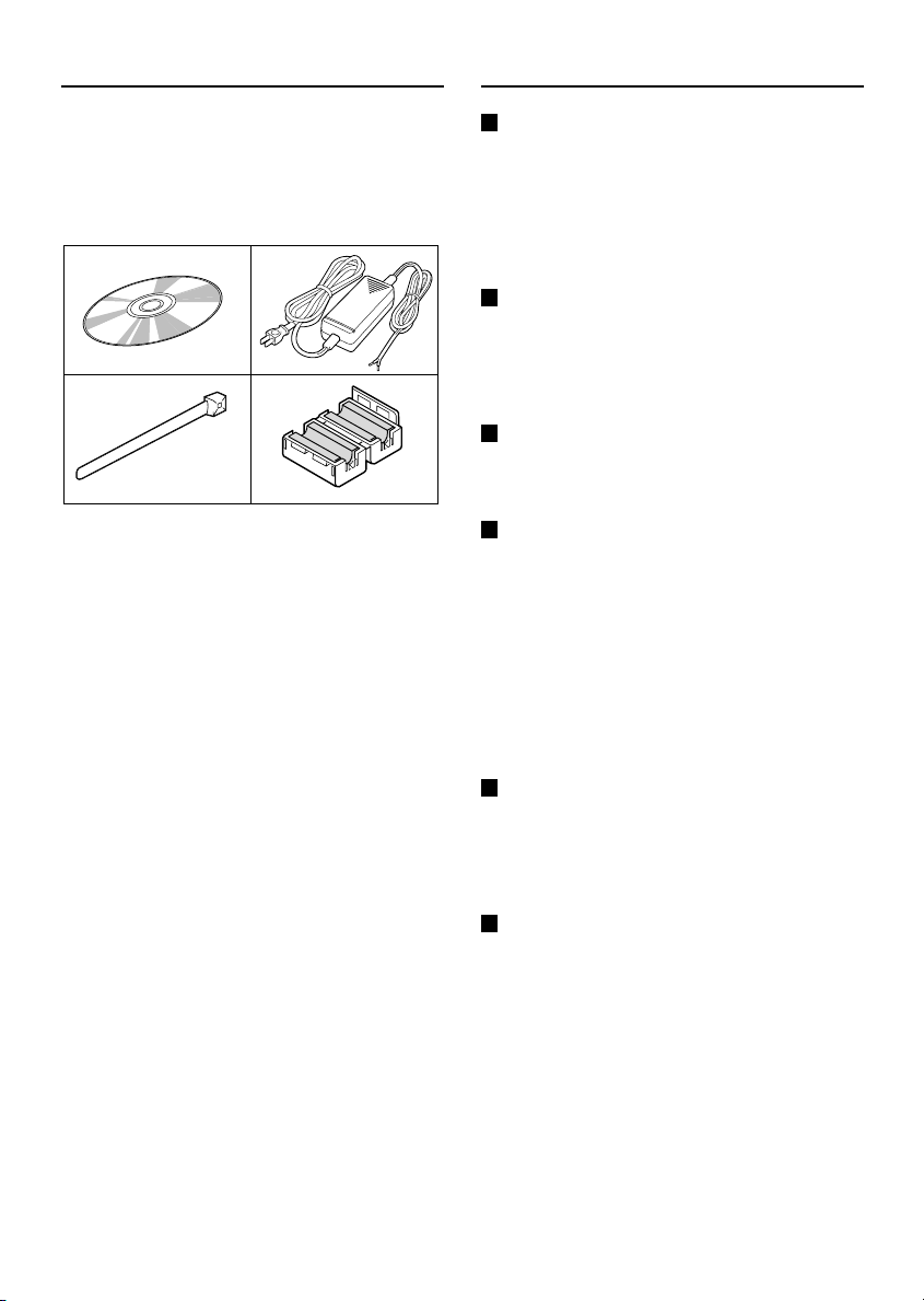
Accessories
Features
1 Setup CD-ROM . . . . . . . . . . . . . . . . . . . 1 pc.
2 AC Adaptor . . . . . . . . . . . . . . . . . . . . . . . 1 pc.
3
Plastic tie . . . . . . . . . . . . . . . . . . . . . . . . 1 pc.
4 Ferrite core . . . . . . . . . . . . . . . . . . . . . . . 3 pc.
12
34
Web Server Function
This video server is equipped with a web server
function. The video server can be accessed
using a computer’s web browser in order to view
images for up to four input signals (4 screen split
screen). In addition, up to a maximum of 16
users can simultaneously access a single video
server on the network.
Network Connections
This video server is equipped with both an
Ethernet connector and an RS-232C connector,
allowing it to be connected to a variety of
different network environments, such as LANs
and the Internet.
Wireless LAN Compatibility
The video server can also be used in a wireless
LAN environment by installing the specified
wireless LAN card.
Adoption of JPEG2000
The images captured by the video server are
compressed using the JPEG2000 format before
transmission. In comparison to conventional
JPEG formats, this format produces very little
image deterioration and allows large volumes of
data to be transmitted quickly (maximum 30 fps).
Note: The transmission rate will vary depending
on individual network conditions.
A network environment that can transmit
data at high speeds is required in order to
transmit data at 30 fps.
Alarm Recording and Playback Functions
The built-in motion sensor detects movement,
and the video server can also be connected to
an external alarm sensor that is set to detect
abnormalities, so that images can be recorded
and played back when an alarm occurs.
Communication function (RS-485)
Communication output via SSP (Sanyo Security
Protocol) (using the RS-485 connector) allows
the video server to be controlled by other
devices such as cameras and multiplexers by
remote control.
English
– 3 –

Operating environment
The video server requires the following
conditions to operate.
OS: In this manual, the Microsoft
•
98 operating system, the Microsoft
Windows® Millennium Edition operating
system, the Microsoft
operating system and the Microsoft
Windows® XP operating system are all
referred to as Windows.
Microsoft and Windows are trademarks, or
registered trademarks of Microsoft
Corporation in the United States and/or other
countries.
CPU: Intel
•
or similar with equivalent speed capacity
(Pentium
Intel and Pentium are trademarks or
registered trademarks of Intel Corporation or
its subsidiaries in the United States and other
countries.
Memory: 128 MB or more (256 MB or more
•
recommended)
Drive: CD-ROM drive
•
Network card: 10Base-T / 100Base-TX
•
Protocols: TCP/IP, PPP, FTP, HTTP
•
Browser: Microsoft Internet Explorer 5.5
•
SP2 or later
Computer monitor display size of 1024 x
•
768 pixels or greater
®
Pentium® III 800 MHz or higher
®
4 2 GHz recommended)
®
Windows® 2000
®
Windows
®
®
®
– 4 –
English
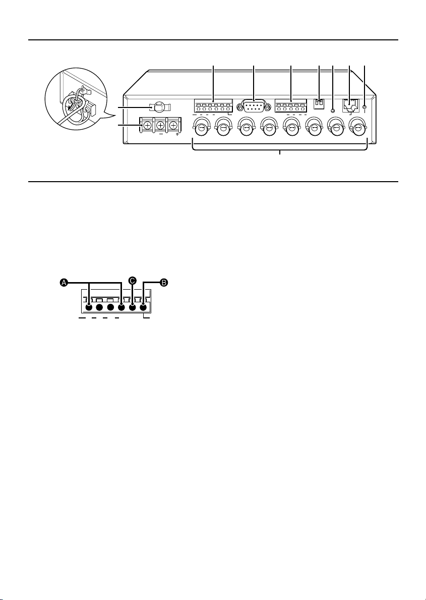
Name and Function of Each Part
3 4 5 6 7 8 9
1
2
GND
12VDC
ALARM
IN
IN OUT
VIDEO 1
ALARM
OUT
RS-232C
IN OUT
VIDEO 2
COMCOM
F
A123 4
B AB
IN
VIDEO 3
ON
TERMI
RS485
OUT
12
PC
MODEM
ETHERNET ALL RESET
IN OUT
VIDEO 4
Power cord holder
1
Secure the power cord to the holder using a
plastic tie or similar as shown in the
illustration.
Power supply input terminals
2
(DC 12 V, GND)
ALARM IN/OUT terminals
3
ALARM
123 4
IN
A
ALARM IN terminals (ALARM IN 1 – 4)
COM
ALARM
OUT
These alarm input terminals are for
connecting to the video servers. Connect
an infrared sensor or similar device to the
terminals to use in detecting intruders.
B
ALARM OUT terminal
Connect a buzzer or lamp to this terminal
to notify you when an alarm has been
detected.
C
Ground terminal (COM)
RS-232C connector (RS-232C)
4
Use this connector to connect the video
server to a modem for transmission of data
along telephone lines, or for connecting the
video server to a computer.
Use the communication/terminal select
switch to change the video server operation
between modem and computer operation.
RS-485 connector (RS-485)
5
Use this connector when connecting the
video server to a device that is equipped with
an SSP (RS-485) communication function.
After making the connection, select the
connected device in the SSP sub-menu of
the main menu so that the device can be
operated by remote control via the network.
Communication/terminal select switches
6
(1) TERMI
When using RS-485, set this switch to
ON for the last device connected.
(2) PC/MODEM
PC: This is for service technician use,
•
and should not be used by the customer.
MODEM: This position should be
•
selected when a modem is connected
using PPP settings.
Note:
Make sure that the video server’s power is
•
turned off before setting the function of the
RS-232C connector.
Using the RS-232C connector to connect the
•
video server to a computer is only done for
service purposes. You should not use the
PC/MODEM select switch yourself.
Link indicator
7
This indicator illuminates when the video
server is connected to a network. It flashes
while data transmission is in progress.
English
– 5 –
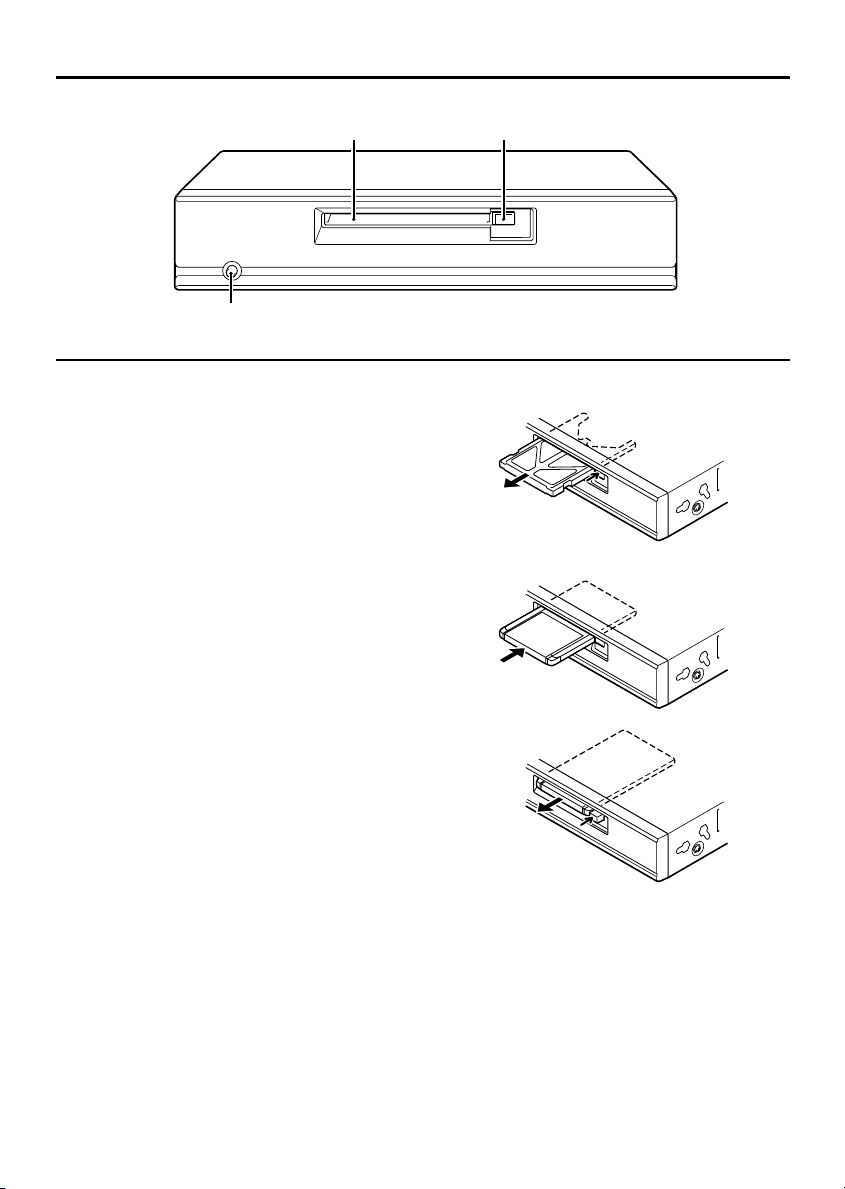
Name and Function of Each Part
H I
POWER
G
ETHERNET connector
8
Use this connector to connect the video
server to a hub, local server or network
server. Use a 10Base-T or 100Base-TX
(Category 5, UTP) cable to make the
connection.
ALL RESET button
9
This button restarts the system. The settings
that have been changed in the setting menus
are not affected.
VIDEO IN/OUT terminals
F
Video input terminals (VIDEO IN 1 – 4)
•
Connect these terminals to the output
terminals of the monitoring cameras.
Video output terminals (VIDEO OUT 1 – 4)
•
Connect these terminals to a monitor for
pass-through output of the images to the
monitor.
POWER indicator
G
This indicator illuminates when 12 V DC is
supplied to the power terminals.
PC card slot
H
Insert a memory card or wireless LAN card
into this slot. At the time of shipment from the
factory, a dummy card is inserted to prevent
dust and other foreign particles getting inside
the unit. If using a PC card, press the PC
card eject button to remove the dummy card
before inserting the PC card.
PC card eject button
I
– 6 –
English
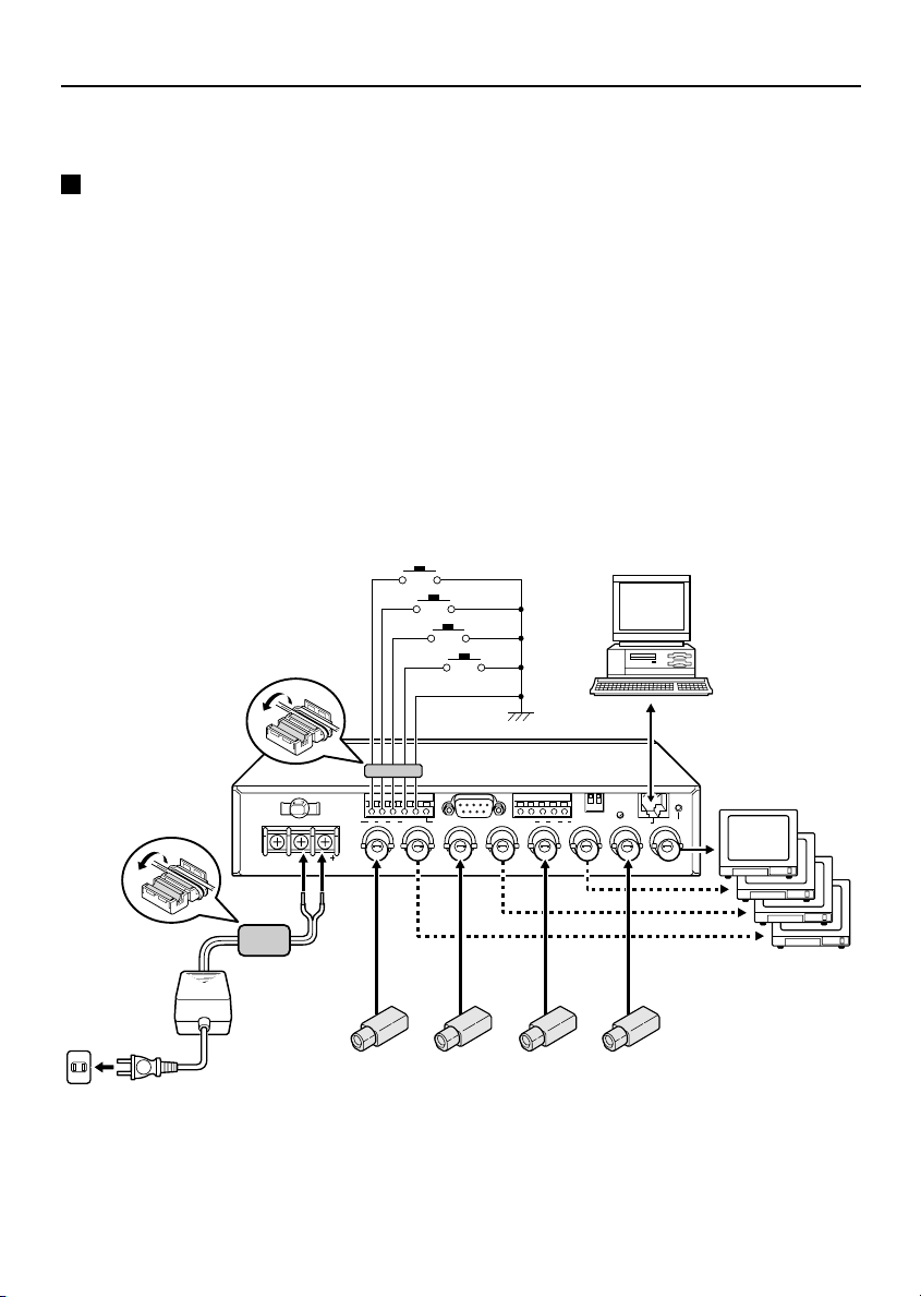
Connections
Turn off the power for all equipment before making any connections.
Basic Connections
1
Connect the video server to a computer.
Connect a cable between the ETHERNET connectors of the video server and the computer.
Use a crossed wire-type Ethernet cable.
2
Connect the accessory AC adapter to the video server.
After connecting the AC adapter, install the supplied ferrite core.
Note:
In order to avoid any problems with the video server and the power supply, take sufficient care to
•
ensure that the polarities are correct when connecting the power supply.
When the accessory ferrite cores are attached, they will increase the load on the cable, so after
•
doing the installation, adjust the cable accordingly.
3
Insert the power cord plug into a wall outlet.
The POWER indicator will illuminate.
Computer
2
English
1
PC
12
MODEM
ON
TERMI
A1234
COMCOM
B AB
RS485
ETHERNET ALL RESET
OUT
IN
VIDEO 3
IN OUT
VIDEO 4
12VDC
ALARM
IN
2
GND
IN OUT
VIDEO 1
ALARM
OUT
RS-232C
IN OUT
VIDEO 2
Monitor TV
3
CCD camera
– 7 –
Connections
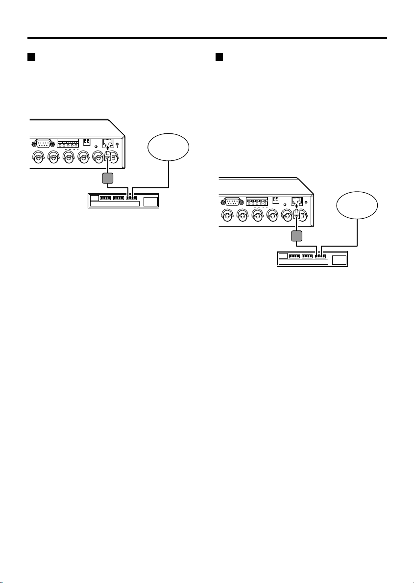
Connecting to a LAN
Use an Ethernet cable to connect the
ETHERNET connector of the video server to the
LAN’s Ethernet switching hub.
Use a straight-type Ethernet cable.
☞
PC
12
MODEM
ON
LARM
OUT
RS-232C
IN OUT
VIDEO 2
TERMI
A
COM
B AB
RS485
IN
OUT
VIDEO 3
Ethernet cable
(straight type)
Ethernet switching hub
ETHERNET ALL RESET
IN OUT
VIDEO 4
LAN
Connecting to the Internet
Use an Ethernet cable to connect the
ETHERNET connector of the video server to a
device such as a router or ADSL modem that is
connected to the Internet.
If connecting to a router, use a straight-type
☞
Ethernet cable. If connecting to an ADSL
modem or to some other type of device, refer
to the documentation provided with the
device for details on what type of connection
method should be used.
PC
12
MODEM
ON
LARM
OUT
RS-232C
IN OUT
VIDEO 2
TERMI
A
COM
B AB
RS485
IN
OUT
VIDEO 3
Ethernet cable
(straight type)
Router or ADSL modem
ETHERNET ALL RESET
IN OUT
VIDEO 4
Internet
– 8 –
English
Network Video Server (Wired LAN) Settings
In order to use the network video server, you must make the following settings in the order given.
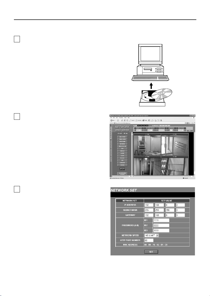
1
Installation of Plug-in Software to the
Computer (p. 10)
Install the contents of the supplied setup
CD-ROM to the computer.
Note: The same setup CD-ROM is
supplied with both the network
camera and the network video
server. You can use either CD-ROM
to carry out the installation.
2
Wired LAN Settings (p. 13)
Connect an Ethernet cable between the
network video server and the computer and
then make the required initial settings such
as the computer IP address, user name,
password and language.
When these settings are completed, the
initial network video server screen will be
displayed. This section gives descriptions of
the various parts of the initial screen for you
to refer to.
Computer
3
Network Connection Settings (p. 18)
This screen lets you carry out operations
such as setting access levels
(Administrator, Operator or User) and
changing passwords.
English
– 9 –
Network Video Server (Wired LAN) Settings
1 Installation of Plug-in Software to the Computer
Install the plug-in software (on the setup CD-ROM) onto the computer that is to be used. Installing the
plug-in software makes it possible to view live images from network video servers using the computer’s
web browser.
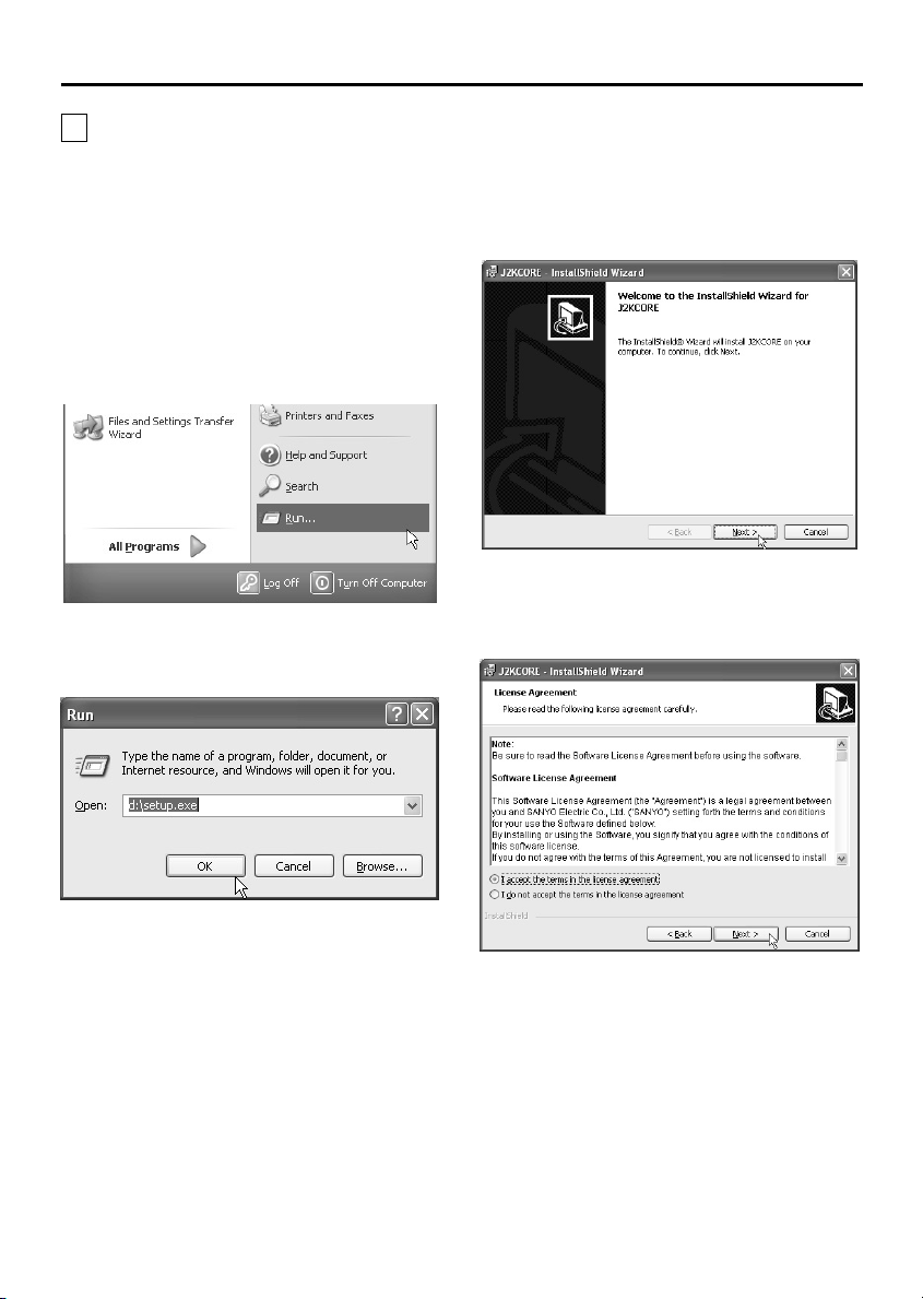
1
Turn on the power for the computer.
After Windows has loaded, continue to the
next step.
2
Insert the setup CD-ROM into the CD-ROM
drive of the computer.
3
Click “Start” and then click “Run”.
4
Type “D:\Setup.exe”.
Type the drive letter for the CD-ROM drive of
the computer in place of “D”.
6
Click the [Next] button.
7
Read the license agreement, and select “I
accept the terms in the license
agreement” if you agree to the terms of
the license. Then click the [Next] button.
5
Click the [OK] button.
After a short wait, the installation window will
appear.
Note: Simply answer the prompts that
appear on the screen in order to
continue installing the software. The
installation program has been set up
beforehand to install the software
correctly.
– 10 –
English
Network Video Server (Wired LAN) Settings
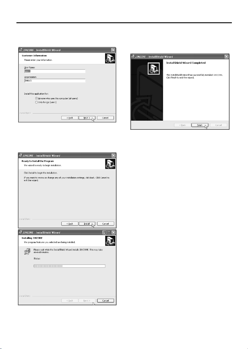
8
Type in your username and organization
name, and then click the [Next] button.
9
Click the [Install] button.
Installation of the software will start and the
window display will change to show the
installation progress.
10
Click the [Finish] button.
This completes the installation of the
plug-in software.
(Uninstalling the plug-in software)
To uninstall the plug-in software, select
“Add/Remove Programs” from the Windows
Control Panel, and delete “J2KCORE”.
English
– 11 –
Network Video Server (Wired LAN) Settings
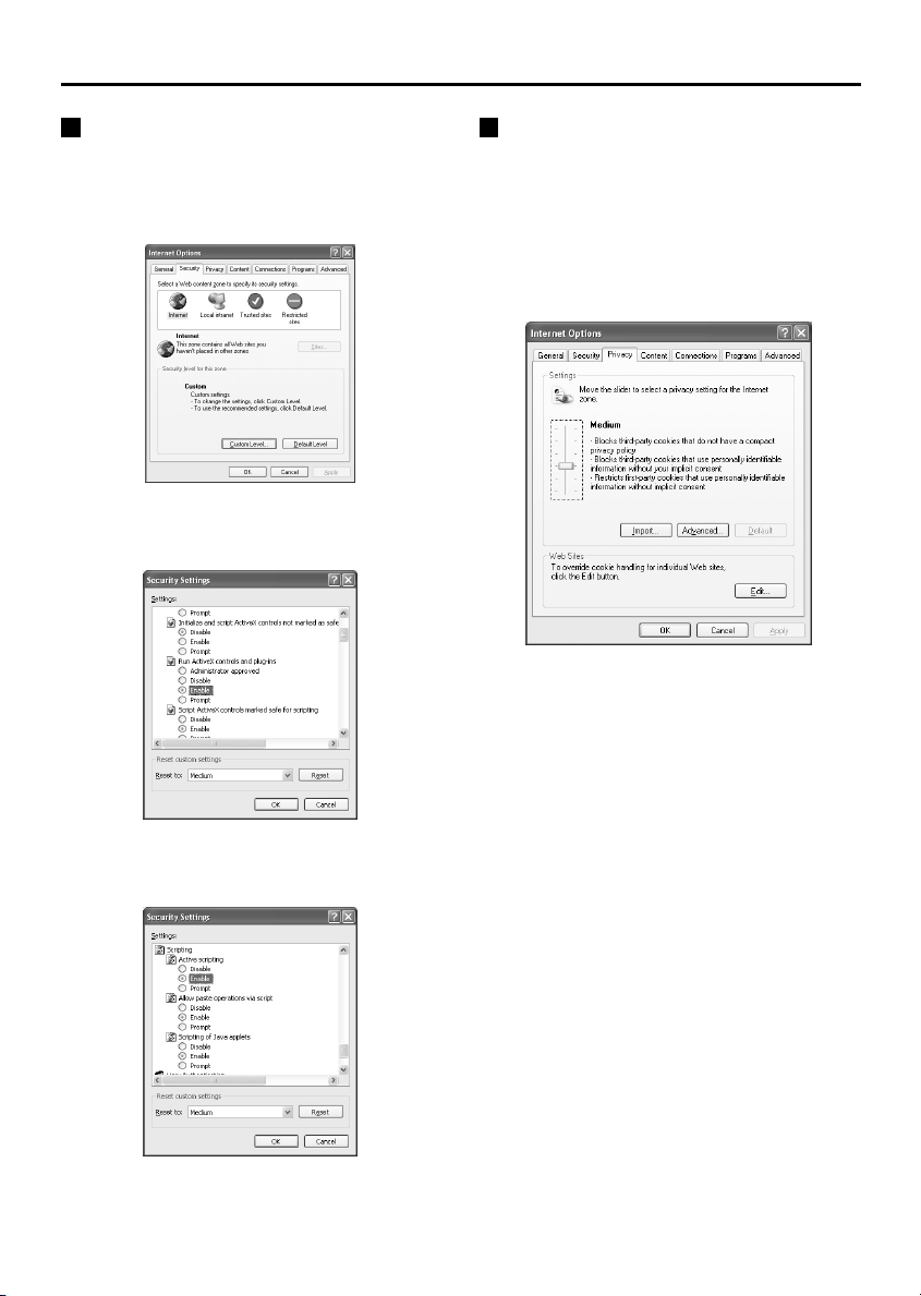
Browser Settings
Check that the Security settings for Microsoft
Internet Explorer are set as described below.
Select Internet Options from the Tools menu,
click the Security tab and then click the Custom
Level button to display the settings.
1
Click “Enable” for “Run ActiveX controls
and plug-ins” in the “ActiveX controls and
plug-ins” section.
Cookie Settings
The video server uses cookies.
If using Internet Explorer Version 6.0 as the web
browser, select Internet Options from the Tools
menu, click the Privacy tab, move the slide bar
to the “Medium” or lower position and then click
the [OK] button.
Note: If using Internet Explorer Version 5.5 SP2,
click the Security tab.
2
Click “Enable” for “Active scripting” in
the “Scripting” section and then click the
[OK] button.
– 12 –
English
Network Video Server (Wired LAN) Settings
2 Wired LAN Settings
Once the plug-in software has been installed, use the computer’s web browser to access the video
server.
Note: The network video server handles large volumes of image data that has been compressed into
JPEG2000 format. In order to provide smooth access to the video server, you should close any
other applications that you do not need to have open.
1
Use an Ethernet cable to connect the
network video server and the computer.
Refer to “Basic connections” in the
“Connections” section.
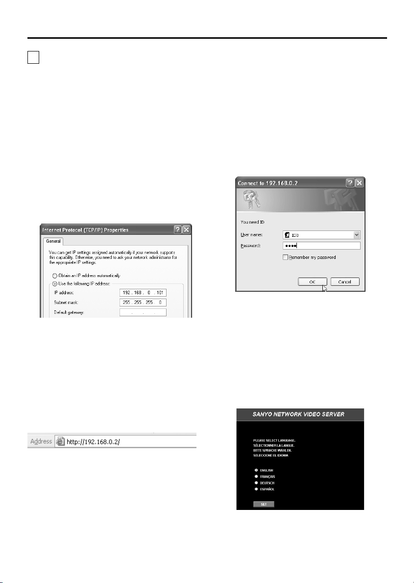
2
Click on the Network Connections icon in
the computer’s Control panel, and then
make the Internet protocol settings (IP
address and subnet mask) for the
computer.
IP address setting:
•
The video server’s IP address is set to
“192.168.0.2”, so type in a spare number
that is 3 or higher for the IP address.
Example: “192.168.0.101"
Subnet mask setting:
•
Type in “255.255.255.0”.
3
Start the web browser on the computer,
type “http://192.168.0.2/” into the location
bar and then press the [Enter] key.
4
Type in the username (ID3) and the
password (3333), and then click the [OK]
button.
The language selection window will be
displayed.
Note: The username and password settings in
this screen are initially set to the
Administrator level settings (ID: “ID3”;
password: “3333”) so that all required
settings can be made. There are separate
passwords for each of the three access
levels (Administrator, Operator and User),
and the passwords can be changed.
Refer to “Access Level Settings” for
further details.
Language selection window
The password entry window will be displayed.
English
The initial screen will be displayed.
– 13 –
Network Video Server (Wired LAN) Settings
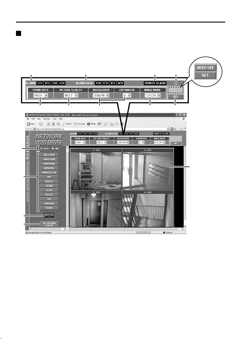
Initial Video Server Screen
The initial screen is displayed once the network video server and the computer have been set. The
initial screen contains the buttons that are required for making various settings, and it also shows live
images from the network video server that have been compressed into JPEG2000 format.
1
2
3
4
5
9
F
67
GH
8
I
J
Image quality mode select buttons
1
Selects the quality for the live images that are
being transmitted.
Available settings:
AUTO: (default setting)
•
The live images being transmitted are
automatically adjusted in accordance with the
computer.
FINE:
•
The live images being transmitted are
displayed at high quality. The actual image
display quality will vary depending on the
original quality at the time of transmission.
Note: The quality of the images will vary
depending on the capabilities of the
computer. If this is a problem, change the
setting to “FINE”. However, when fine
mode is selected, the image display
speed will be slower.
– 14 –
English
Network Video Server (Wired LAN) Settings
[CLOCK] button
Menu select buttons
2
The live image display area and setting area
changes when you click on one of these buttons.
[MULTI VIEW] button
•
This button is used to display images from
cameras that are connected to the VIDEO IN
terminals of the video server in a 4-screen
split screen. This screen is displayed
automatically when a menu screen is
displayed.
Note:
If no live images are being displayed in the
4-screen split screen, the display appears as
follows.
VIDEO LOSS: Appears when a video input
☞
signal is present, but suddenly for some
reason (such as an accident) the signal gets
disconnected.
SANYO: Appears when no video input signal
☞
source is connected. In addition, it appears
when the DISPLAY setting for the camera
title is set to “OFF”.
[SINGLE VIEW] button
•
Click this button to operate the devices that
are connected to the video server (such as
dome cameras, time lapse VCRs,
multiplexers or digital video recorders) singly
or as a group.
[VIEW FRAME] button
•
If the live images are displayed in a 4-screen
format, the images at either side may not be
visible. In such cases, click this button to
display live images in a single screen. The
image area will be displayed in a fixed image
size (720 x 480).
[NETWORK] button
•
Used when making network settings.
[WIRELESS LAN] button
•
Used when making wireless LAN settings.
[PPP] button
•
Used when setting up an Internet connection
using a modem.
Archive software (sold separately) is required
when using these settings.
[DISPLAY] button
•
Used when making settings such as camera
title and image quality (aperture and contrast)
for a camera.
[ALARM] button
•
Used when making settings for alarm
recording and motion sensors.
•
Used when setting the video server’s clock.
[RS-232C] button
•
Used when setting the communication speed
when the video server is connected directly
to the computer.
[SSP] button
•
Use this button to carry out SSP control.
[LANGUAGE] button
•
Click this button if you would like to change
the language. The language selection screen
will be displayed.
[STATUS] button
•
Used when checking firmware versions and
information relating to the video server.
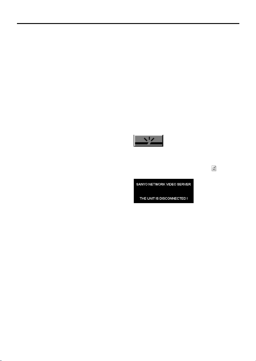
Network disconnect button
3
Click this button to shut down operation of the
network video server. The following message will
be displayed when this button is clicked. To
reconnect the video server, click the (Refresh)
button in the title bar.
[Get JPEG2000 PLUG-IN] button
4
If you need to install the JPEG2000 plug-in
software, click this button to point the browser to
a website page for downloading the software.
Select “JPEG2000 Plug-in Software” and then
start the download. You will need an Internet
connection in order to download the software.
English
– 15 –
Network Video Server (Wired LAN) Settings
Grey indicator:
ALARM indicator
5
The alarm status of each video server is
indicated by these ALARM indicators.
Off: No alarm data, or recording of images is
•
complete
Lit red: Post-alarm recording in progress
•
Lit orange: Pre-alarm recording in progress
•
ALARM DATA indicator
6
The alarm recording status of each video server
is indicated by these ALARM DATA indicators.
Lit red: (alarm recording image playback
•
is possible)
Internal memory or expanded memory
(installed in the PC card slot) is filled by
alarm recording images.
Lit orange: (alarm recording image
•
playback is not possible)
Alarm recording images are currently being
transferred from internal memory to
expanded memory, alarm recording is in
progress, or and expanded memory error has
occurred.
Lit green: (alarm recording image
•
playback is possible)
Alarm data can still be recorded into the
expanded memory.
Note: Refer to “Alarm Settings” for further
details on alarm recording. (p. 26)
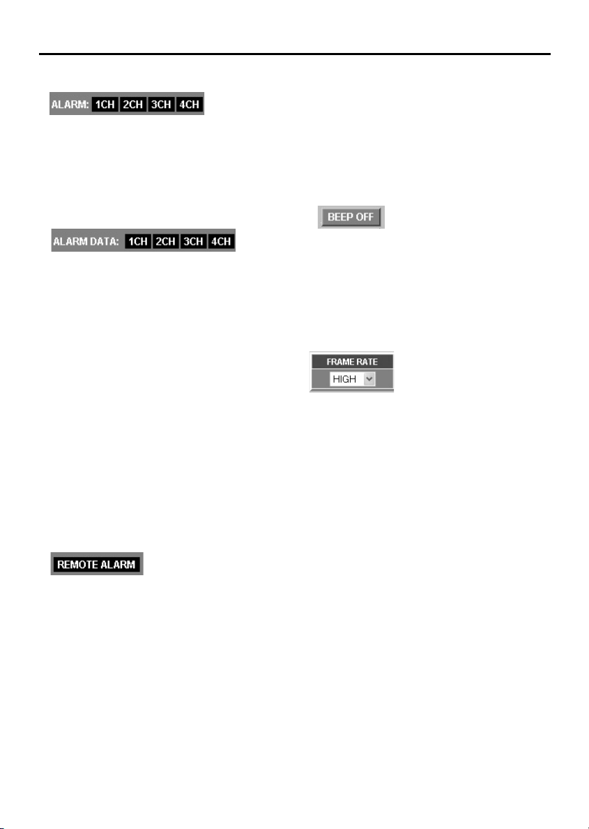
REMOTE ALARM indicator (p. 32)
7
If “ALARM OUT MODE” is set to “REMOTE
CONTROL” (remote alarm operation indicator
display: black), the output status from the alarm
output connector can be set to continuous output
or timed output.
Black indicator:
•
No output status when “ALARM OUT TIME”
has been set.
Red indicator:
•
Output status when “ALARM OUT TIME” has
been selected. When the set time is
exceeded, the indicator changes to black, but
if you click the indicator once more, the
specified indicator illuminates.
•
No output status when “ALARM OUT TIME”
is set to “REMOTE”.
Orange indicator:
•
Output status when “ALARM OUT TIME” is
set to “REMOTE”. The output status can be
turned on and off repeatedly by clicking the
indicator.
BEEP OFF indicator (p. 27)
8
If “ALARM SOUND MODE” is set to “USE”, this
display appears at the same time as the buzzer
sounds when an alarm is detected. Click the
indicator to stop the alarm buzzer from sounding.
The alarm buzzer will stop automatically when
alarm recording is complete.
FRAME RATE setting
9
(default setting: HIGH)
Set the image transmission speed from the
drop-down list box. Images can be transmitted at
maximum speed depending on the network
environment that the video server is connected
to.
For example, if the maximum transmission
speed for the network being connected to is 15
fps, then the images can only be transmitted at a
maximum speed of 15 fps, even if the frame rate
is set to “MID 3” or higher.
Available settings:
BASIC (5 fps), MID 1 (10), MID 2 (15), MID 3
(20), HIGH (30)
– 16 –
English
Network Video Server (Wired LAN) Settings
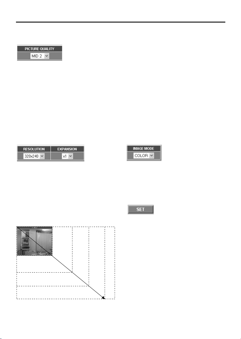
PICTURE QUALITY setting
F
(default setting: MID 2)
Use the drop-down list box to select the image
quality (image compression ratio). If a higher
compression ratio is used (BASIC), the volume
of image data becomes smaller (the amount of
image deterioration becomes greater) and the
transmission speed becomes faster.
Available settings:
BASIC, MID 1, MID 2, MID 3, HIGH
Note: Alarm recording is carried out at the
picture quality that is specified in the
alarm recording settings, not at the setting
that is made here. (p. 35)
RESOLUTION and EXPANSION settings
G
(default settings: 640x480, x1)
Select the image resolution from the
•
drop-down list box. The volume of data
transmitted will be larger when a higher
resolution is selected.
Use the drop-down list box to set the
•
enlargement ratio to x2 or x4 (when the
image size is 160x120) or x2 (when the
image size is 320x240). The image will
appear coarser when a greater enlargement
ratio is selected.
(Selection screen example)
160x120
320x240
Note:
When images that are compressed using
•
JPEG2000 are played back, the image refresh rate
will vary depending on the performance
specifications of the computer being used. In
addition, if other applications besides the web
browser are running, this may also cause the image
refresh rate to become slower or may result in
unstable operation. You should avoid running other
applications at the same time as much as possible.
Set the FRAME RATE, PICTURE QUALITY
•
(COMPRESSION RATIO) and RESOLUTION
settings to levels that will not interfere with the
operation of the network. If the amount of data being
transferred is too large for the network environment,
it may have an adverse effect on other network
operations.
The picture quality and image resolution cannot be
•
changed when pre-alarm recording has been set.
IMAGE MODE setting
H
(default setting: COLOR)
Select whether live images are to be displayed in
color or black and white from the drop-down list
box.
If you select “GRAY” for black and white images,
the amount of data transmitted will be reduced,
so that the transmission speed can be increased.
[SET] button
I
Click this button to accept the settings that have
been made using the drop-down list boxes.
Image display area
J
Live images are displayed when the [MULTI
•
VIEW], [SINGLE VIEW] or [VIEW FRAME]
menu select button is clicked.
When the other menu select buttons are
•
clicked, the respective setting screens are
displayed.
640x480
720x240
English
720x480
– 17 –
Network Video Server (Wired LAN) Settings
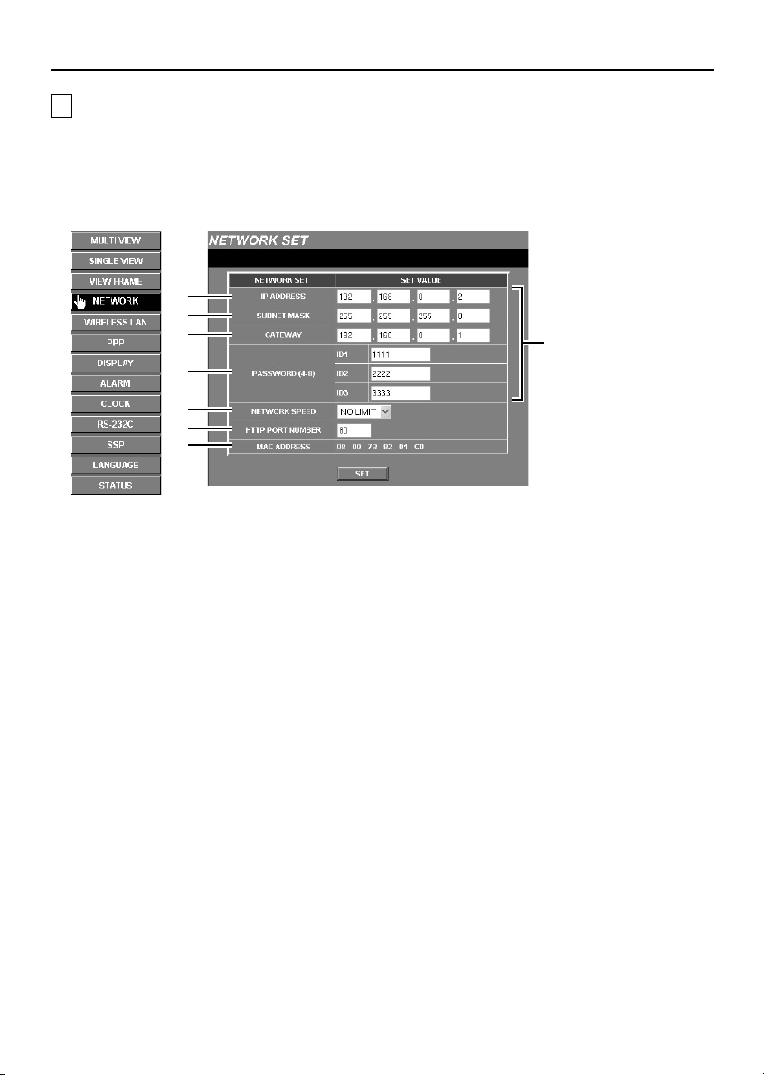
3 NETWORK SET Settings
These settings are used in order to connect the video server to the network. After these settings have
been completed, you may also have to make wireless LAN settings or PPP settings. More than one
video server can be connected to the same network, but in order to do this, you will need to make
settings for each video server such as assigning separate IP addresses before connecting the video
server’s to the network.
1
2
3
4
5
6
7
Click the [NETWORK] menu select button.
☞
The NETWORK SET screen will be displayed,
and the default settings for each item will be
displayed automatically.
Once you have completed making the settings,
click the [SET] button.
Note: Check with the network system
administrator or Internet Service Provider
if you need to change the IP address 1,
subnet mask 2 or gateway 3 settings.
Set the password.
4
There are three access levels available (User,
Operator and Administrator) and separate
passwords can be set for each level. The factory
default settings are shown in Table 1 (p. 21),
and the range of operations varies as indicated
for each access level.
Note: It is recommended that you change the
passwords whenever possible for security
purposes. (p. 19)
NETWORK SPEED
5
This sets the speed of data transmission by the
video server.
Available settings:
64, 128, 256, 512, 1024 (Kbps), NO LIMIT
(Default setting: No limit for transmission speed)
HTTP PORT NUMBER
6
(default setting: 80)
This setting is used when more than one video
server is connected to a broadband router and a
single IP address for that router is being used to
make the images being monitored by the video
server publicly available over the Internet. Refer
to the documentation provided with the
broadband router for further details.
Normally the HTTP PORT NUMBER setting
should be left “80” without being changed, even
if more than one video server is connected to the
network.
Default settings displayed
Reset if necessary
– 18 –
English
Network Video Server (Wired LAN) Settings
If a user at Administrator level accesses a video
MAC ADDRESS display
7
This shows the Mac address for the video server.
Note:
Up to a maximum of 16 individual users can access
•
a single video server on the network at the same
time. However, only one user out of this maximum
of 16 users can be accessing at Operator or
Administrator level at any one time.
Depending on the network environment, it may not
•
be possible for 16 users to be connected to a video
server at the same time. Once a user has accessed
a video server, the network may not allow further
accesses, so if this happens, change the resolution
for the transferred data (by reducing it) or change
the compression ratio (by increasing it) to reduce the
volume of data being transferred.
If a 17th user tries to access a video server, the
•
message “THE UNIT IS BUSY!” will be displayed on
their screen. Depending on the network
environment, the message “THE UNIT IS BUSY!”
may be displayed on a user’s computer screen even
when less than 16 users are accessing a video
server.
Changing a password
•
server while a user at Operator level is accessing
the video server, the Administrator level user will
have priority. In such cases, the Operator level user
will be disconnected and the message “THE UNIT
IS DISCONNECTED!” will be displayed on their
screen.
If an Operator or Administrator attempts to access
•
the video server while another user with the same
access level is accessing the video server, the
second access will have priority. In such cases, the
first access will be disconnected, and the message
“THE AUTHORIZED USER LOGGED IN!” will be
displayed on that user’s computer screen.
Depending on the network environment, the speed
•
of data transmission to users may drop if the
number of users accessing the same video server
increases, and operations such as refreshing of
images may become delayed.
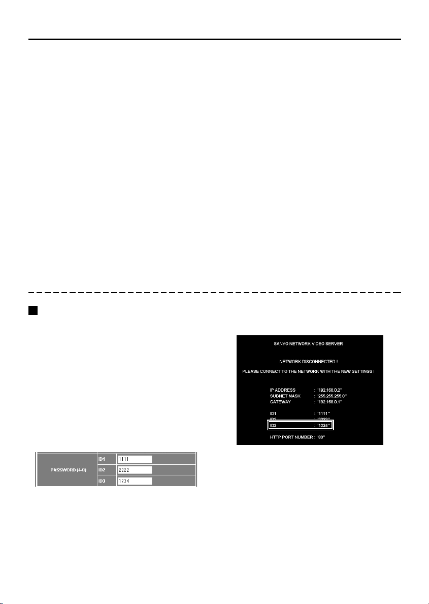
Example: To change the password for the
Administrator level (ID3) to “1234”
Passwords can consist of between 4 and 8
numerals.
Delete the current password (“3333”) in
☞
the password column for ID3, type “1234”
as the new password for ID3, and then
click the [SET] button.
The following window will be displayed.
Check that the details are correct, and then
close the window.
English
(When a password has been changed)
When the video server and computer are
connected once more, the password entry
screen will be displayed, so check the username
and type in the new password (“1234”) in the
password column for ID3.
– 19 –

Network Video Server (Wired LAN) Settings
Viewing Live Images Without
Typing In a Username or
Password (ID1 only)
Normally you need to type in a password at the
password entry screen in order to display the live
image screen. However, if you make the settings
described below, you can view the live image
screen without having to type in a password. In
this case, you will be logged in at user level “ID1”.
1
Delete the password in the password
column for ID1, and then click the [SET]
button.
The following window will be displayed.
Check that the ID1 password is blank, and
then close the window.
Changing the Access Level (ID2
or ID3)
If live images are monitored without using a
password, the [SET] button will change to
“CHANGE ID”. To change the access level to
“ID2” or “ID3”, follow the procedure below.
1
Click the [CHANGE ID] button at the
top-right of the live image screen.
The password entry screen will be displayed.
Note:
The password entry screen can also be
displayed when the ALARM DATA LIST screen
is displayed by clicking the ALARM DATA
indicator (button).
2
Type in the user name and password for
the required user level, and then click the
[OK] button.
(Example: ID3, 3333)
The access level will then change to those for
user level ID3 (Administrator).
2
Turn the video server off and then back
on again.
A single-image live image screen will be
displayed.
Note:
If the ID1 password is blank, a single-image
•
live image screen will always be displayed.
To return to normal password entry, type in a
•
password for ID1 (example: 1111).
– 20 –
English

Network Video Server (Wired LAN) Settings
Access Level Settings
When operating the network video server, you need to select an access level to either limit operations
to only the monitoring of live images or to allow menu settings to be changed as well.
The access level setting depends on the “Username” and “Password” that are typed in after the wired
LAN settings have been made. (p. 13)
The default passwords for each user level are given below. Change the passwords for each access
level as required when using the network video server.
Table 1
Username/password Access level
For Administrator access level All operations and settings can be carried out.
Username: ID3
Password: 3333
For Operator access level The following buttons and the transmission setting menu
Username: ID2
Password: 2222
For User access level Only the following buttons can be operated.
Username: ID1
Password: 1111
In order to make it easier to carry out the various video server operations described in this Instruction
Manual, the usernames (_ID1_, _ID2_ and/or _ID3_) are indicated in the top-right corner of each page.
For example, if _ID3_ appears, then the operation is only available at the Administrator level.
can be used. The ALARM DATA LIST screen cannot be
displayed.
The transmission setting menu in the live image screen is
disabled.
The ALARM DATA LIST screen cannot be displayed.
English
– 21 –
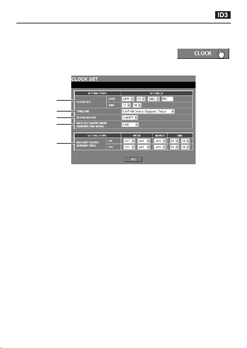
CLOCK SET Settings
This lets you set the video server’s internal clock. You can also make settings for summer time.
Click the [CLOCK] menu select button.
The CLOCK SET screen will be displayed. Set the date and time using the
drop-down list boxes, and then click the [SET] button.
The clock starts counting from the time that has been set only if “CLOCK
ADJUST” is set to “UNSET”.
Note: To return to the live image screen, click the [MULTI VIEW] button.
1
2
3
4
5
DATE and TIME settings
1
The default time setting is 00:00 on Jan 01 2003.
Set the DATE and TIME. The weekday will be
set automatically.
TIMEZONE
2
This lets you set your standard time zone. Select
the time zone for the video server’s location.
CLOCK ADJUST setting
3
This synchronizes the video server’s time with
the computer’s time.
Select the time setting from the drop-down list
box, and then click the [SET] button.
UNSET: If the time has not been set when
•
you log in (default setting), it will be set
automatically.
LOGIN: The time is set automatically each
•
time you log in.
OFF: The time is not set.
•
Note: Make sure that the computer’s time is set
correctly.
DAYLIGHT SAVING MODE
4
The daylight saving settings are displayed when
“USE” is selected from the drop-down list box.
Available settings:
USE: Daylight saving time is used.
•
When set to “USE”, you can then set the
times for daylight saving to be applied.
NO USE: Daylight saving is not used.
•
DAYLIGHT SAVING
5
When the set date and time is reached, the
video server’s time automatically changes from
standard time to summer time. You need to set
the start time (ON) and end time (OFF) for
summer time.
WEEK ... Sets the week and weekday.
Available settings:
Week: 1ST, 2ND, 3RD, 4TH, LST
•
Day: SUN, MON, TUE, WED, THU, FRI, SAT
•
MONTH ... Sets the start month and end month
TIME ... Sets the hours and minutes.
for summer time.
– 22 –
English

DISPLAY setting
Click the [DISPLAY] menu select button.
You can create camera titles for each camera and have them appear in the
camera title display of the “LIVE” screen.
Setting the camera title
You can set camera titles for each camera.
1
Move the cursor to the current camera
title (example: CH_1), and delete this
camera title.
2
Type in the new camera title (example:
CAM_1, 2, 3, 4).
The camera title can consist of up to eight
alphanumeric characters and the underscore
character.
Note:
The only characters that can be used in camera
titles are alphanumeric characters. If any other
characters are entered, they will appear as “_”
(underscore).
3
Click the [SET] button.
The camera title that has been typed in will
be saved, and it will appear in the camera
title display area on the live image screen.
English
– 23 –

DISPLAY setting
Turning Off Video Image Display
If “DISPLAY” is set to “ON” while a 4-screen
multi view screen is being displayed, the
images will be displayed. To change any of
the screens so that no images are displayed
in that screen, change the “DISPLAY” setting
for that screen to “OFF”.
If the setting is “OFF”, no images compressed in
Note:
JPEG2000 format will be transmitted by the
video server for that screen, so the amount of
transmission data handled by the network will be
reduced.
Setting Image Quality (Aperture
and Contrast)
This lets you set the aperture (contour
correction) and contrast.
APERTURE
1
Select “HIGH” if you want to emphasize the
contours of objects. (Available settings:
NORMAL, HIGH)
CONTRAST
2
Available settings:
LOW: When viewing mainly dark scenes
•
MID: When viewing mainly scenes which are
•
neither bright nor dark
HIGH: When viewing mainly bright scenes
•
1
2
– 24 –
English

SINGLE VIEW Settings
Click the [SINGLE VIEW] menu select button.
This changes the display from a 4-screen display to a single-screen display.
At this time, the channel that was last accessed will be displayed. However,
if the video server is being started for the first time, the images from the
video signals being input will be displayed starting from the smallest
number (1 to 4).
Note: The screen that is displayed when the [SINGLE VIEW] button is clicked will vary depending on
the “SSP CONTROL” setting (ON/OFF). (p. 52)
SSP CONTROL (OFF) SSP CONTROL (ON)
12
English
MULTI VIEW
1
Returns to the multi-screen display.
POP UP
2
The control panel of the SSP control panel can
be displayed in a separate window.
OFF: Only switching between single-screen
and 4-screen display is possible.
ON: The control panel for carrying out SSP
operations for connected devices is
displayed. If a device that is equipped
with SSP is connected, that device can
be operated by remote control.
– 25 –

Alarm Settings
Click the [ALARM] menu select button.
The video server is equipped with two types of alarm function. When an
outside intruder is detected, these alarm functions can be used to record
the images immediately before the alarm occurred (pre-alarm recording)
and the alarm images themselves (post-alarm recording) into the video server’s internal memory or
onto a memory card, and these recorded images can then be played back.
External alarm sensor settings
• When a device such as an infrared sensor is
connected to the ALARM IN terminal at the rear of
the video server and this sensor detects an intruder,
the camera images are recorded in the video
server's internal memory.
• Once “EXTERNAL ALARM” has been set to either
“NO” or “NC”, further detailed settings can then be
made.
• While viewing the live images, you can set sensor
• Detailed settings can be made if the “MOTION
Motion detector settings
marks [ú] in the motion sensor detection area, and
also set the detection sensitivity. When the sensor
detects an intruder, the camera images are
recorded in the video server's internal memory.
DETECTOR” alarm setting is set to “ON”.
1
3
5
7
ALARM
234
IN
2
4
6
Alarm detection and recording
• If an alarm is detected by either an external alarm
sensor or a motion detector, the ALARM indicator
and the ALARM DATA indicator illuminate
simultaneously.
• When images are being recorded in the video
server's internal memory, the ALARM indicator
switches off and the ALARM DATA indicator
illuminates red or green. Playback of alarm
recording images is possible at this time.
8
COM
9
F
G
H
Alarm checking (Output)
• When an alarm has been detected by either an
external alarm sensor or a motion detector, the
alarm status can be checked visually and/or
audibly.
• For example, if an indicator is connected to the
ALARM IN terminal the indicator can be made to
illuminate when an alarm is being received, or if a
buzzer is connected, it can be made to sound at
this time.
– 26 –
ALARM
IN
OUT
COM
ALARM
1
234
English

Alarm Settings
ALARM SET setting
1
This lets you make alarm settings for the video
images from the various connected devices.
Click on a button from [CH1] to [CH4] to display
the ALARM SET screen for that channel. You
can then make various settings such as
selecting external alarms and motion delector.
ALARM REC USE
2
This function stops any motion that occurs
during alarm setting. After the alarm settings
have been made, change this setting to “USE”
so that alarms can be detected in accordance
with the settings.
ALARM OUT
3
This is used to make settings for a device such
as a buzzer that is connected to the ALARM
OUT terminal at the rear of the video server
when an alarm is input.
When “NC” (normal close) or “NO” (normal
open) is selected, the ALARM OUT MODE or
ALARM OUT TIME menu is displayed.
Available settings:
OFF: No alarm is output when an alarm is
•
received.
NC: Normal close (normally closed, but an
•
alarm is output when open).
NO: Normal open (normally open, but an
•
alarm is output when closed).
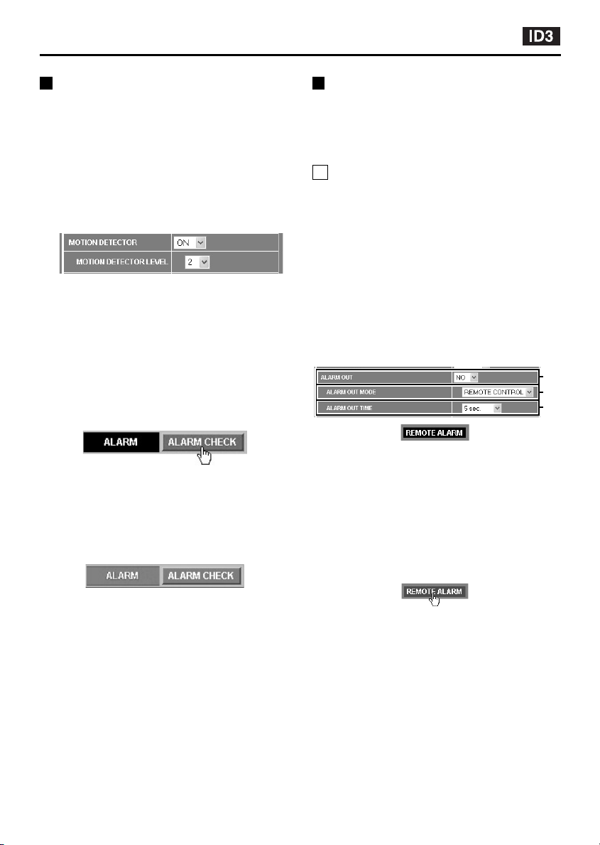
ALARM OUT MODE
4
This operation can be used to manually switch to
output to the ALARM OUT terminal regardless of
whether an alarm is being received or not. When
set to “ON”, the REMOTE ALARM indicator
(black) is displayed in the initial screen. (p. 32)
ALARM OUT TIME
5
This sets the alarm duration when the external
alarm or motion detector detects an alarm.
The “REMOTE” setting only appears when
“ALARM OUT MODE” is set to “REMOTE
CONTROL”. (p. 27)
Available settings:
2, 5, 10, 15, 20, 30, 60 sec.,
2, 3, 4, 5 min., REMOTE
ALARM SOUND MODE
6
This setting causes an alarm warning to sound
when an alarm is detected. If set to “USE”,
“BEEP OFF” appears in the initial screen when
an alarm is detected at the same time as the
alarm buzzer sounds. If you click this indicator,
the alarm buzzer will stop.
ALARM BUFFERING SET
7
This is used to make settings related to
recording alarm images. The screen shown in
“ALARM BUFFERING SET Setting” (p. 28) will
be displayed for you to make detailed settings.
EXTERNAL ALARM
8
Select “NC” (normal close) or “NO” (normal
open) to display the external alarm setting menu.
Available settings:
OFF: No external alarm input is detected.
•
NC: Normal close (normally closed, but input
•
is detected when open).
NO: Normal open (normally open, but input
•
is detected when closed).
MOTION DETECTOR
9
When set to “ON”, the MOTION DETECTOR
SET screen is displayed. Sensor marks (ú) are
used to set the detection area in this setting
screen.
MOTION DETECTOR LEVEL
F
This sets the sensitivity level for the sensor
marks (ú). See p. 32 for details on the sensitivity
level.
English
– 27 –

Alarm Settings
ALARM MODE
G
This selects what combination of external alarm
and motion detector is to be used to provide
alarm input. Make this setting when “EXTERNAL
ALARM” is set to either “NC” or “NO” or
“MOTION DETECTOR” is set to “ON”.
The ALARM OUT terminal settings also need to
be made.
Available settings:
AND: An alarm is generated when both the
•
external alarm and the motion sensor receive
alarm input.
OR: An alarm is generated when either the
•
external alarm or the motion sensor receives
alarm input.
ALARM BUFFERING
H
Set “ALARM BUFFERING” to “ON” for each
channel selected using “ALARM SET”. Then
click the [DETAIL] button in “ALARM
BUFFERING SET” to display the detailed setting
screen for alarm buffering.
ALARM BUFFERING SET Setting
If you click the [DETAIL] button next to “ALARM
BUFFERING”, the ALARM BUFFERING SET
screen will be displayed. This screen is used to
set the way in which the alarm data that is
generated when an alarm is detected is
recorded into the video server’s internal memory.
The recording capacity of the internal memory is
set to a default of approximately 16 MB per
alarm event.
1
2
3
4
5
ALARM DATA SIZE
1
This sets the size for alarm data that is recorded
into the internal memory. The pre/post selection
ratio for the alarm recording area will vary
depending on the size that is set.
Available settings:
16, 12 MB: All available alarm recording area
•
ratios can be selected.
8 MB: The 1/9 pre/post ratio cannot be
•
selected.
4 MB: The 1/9 and 2/8 pre/post ratios cannot
•
be selected.
2 MB: The pre/post ratio is fixed at 0/10.
•
TWO IMAGES: The pre/post ratio is fixed at
•
0/10.
Note:
“TWO IMAGES” can be selected when PPP
•
is being used.
Only a single event can be stored in the
•
internal memory, regardless of the size of the
alarm data.
BUFFERING AREA
2
This sets the ratio between the pre-alarm and
post-alarm recording areas in the internal
memory.
Available settings:
(PRE/POST) 0/10, 1/9, 2/8, 3/7, 4/6, 5/5
PRIORITY
3
This sets the quality for the images recorded in
the internal memory.
PICTURE QUALITY: Alarm images are
•
recorded at high image quality.
TIME: Images are recorded with speed as
•
the priority.
When this setting is made, the time taken for
recording alarm data is reduced.
ALARM RESOLUTION
4
You can set the size of the images that are
recorded in the internal memory to 720x240 or
720x480.
OVERWRITE
5
This setting is only displayed when an internal
memory card is installed.
Always be sure to insert the expansion memory
card into the card slot before turning on the
power for the video server. If you insert the card
after the power has been turned on, this item will
not be displayed.
Note: If this is set to “ON”, old alarm images are
automatically deleted from the expansion
when it becomes full, and the new data
from the internal memory is written over
as it is captured.
– 28 –
English

Alarm Settings
External Alarm Sensor Setting
1
Connect a device such as an infrared
sensor to the ALARM IN terminal at the
rear of the video server.
2
Set “ALARM REC USE” to “NO USE”
(example).
3
Set “ALARM OUT” to “NO” (example).
For example, you can cause a buzzer that is
connected to the ALARM OUT terminal to
sound.
For details, see “3 ALARM OUT”.
4
Set “ALARM OUT MODE” to “ALARM
OUT”.
5
Use the drop-down list box to change the
“ALARM OUT TIME” setting to “60 sec.”
(example).
6
Set “ALARM SOUND MODE” to “USE”.
7
Use ALARM SET to set the camera
channel that you would like to use for
detecting to “CH_1” (example).
The ALARM SET screen for the selected
camera channel will be displayed.
8
2
9
Set “ALARM BUFFERING” to “ON” and
then click the [SET] button.
The display will return to the ALARM
CONDITIONS SET screen.
3
10
Set “ALARM BUFFERING” to “ON”, and
4
5
then click the [DETAIL] button.
The ALARM BUFFERING SET screen will
be displayed.
9
10
11
Change any settings that are required
for recording alarm images into the
internal memory, and then click the
[SET] button.
The display will return to the ALARM
6
CONDITIONS SET screen once more.
For example, you can set the following.
The alarm images (16MB) will be recorded
at high quality at a resolution of 720x240.
8
Set “EXTERNAL ALARM” to “NO”
(example).
For example, if a door is opened, it will trigger
an alarm.
For details, see “8 EXTERNAL ALARM”.
English
7
– 29 –
12
Set “ALARM REC USE” to “USE” and
then click the [SET] button.
When an alarm is detected, the alarm will
sound and the ALARM DATA indicator in
the initial screen will be displayed.

Alarm Settings
(Connection method)
Connect an infrared sensor or similar to
1
the ALARM IN terminal at the rear of the
video server.
Connect a buzzer or lamp to the ALARM
2
OUT terminal.
Once the connections are complete,
install the supplied ferrite core (A) to the
power cord.
Infrared sensor or similar Buzzer or lamp
(A)
1234
IN OUT
VIDEO 1
ALARM
COM
OUT
IN
ALARM
IN
GND
12VDC
MOTION DETECTOR SET Settings
1
Set “ALARM REC USE” to “NO USE”
(example).
2
Use the ALARM SET screen to set the
camera channel that you would like to use
for motion detecting to “CH_1” (example).
The ALARM SET screen for the selected
camera channel will be displayed.
4
Set “MOTION DETECTOR” to “ON”.
The motion detector level and MOTION
DETECTOR SET screen will be displayed.
5
Use the drop-down list box to change the
“MOTION DETECTOR LEVEL” setting
(example: “2”).
The smaller the value selected, the higher
will be the sensitivity. Refer to “Motion
Detector Level Sensitivity Setting” for
further details. (p. 32)
6
Set the sensor marks.
These correspond to the live image screen
and the sensing area.
1
Move the pointer to the same position
(grid area) as the area of the live image
screen that you would like sensing to
be carried out, and then click the
mouse button.
A sensor mark (ú) will be displayed. Click
in the same place once more to clear the
mark.
2
In the same way, insert sensor marks
in other places as required.
1
3
Set “EXTERNAL ALARM” to “OFF”
(example).
2
1
3
4
5
– 30 –
7
Click the [SET] button.
8
Set “ALARM OUT”, “ALARM OUT MODE”,
“ALARM OUT TIME”, “ALARM SOUND
MODE” and “ALARM BUFFERING SET” in
the same way as for “External Alarm
Sensor Setting”.
English

Alarm Settings
External Alarm Sensor and Motion Detector Settings
1
Set “ALARM REC USE” to “NO USE”
(example).
2
Use the ALARM SET screen to set the
camera channel that you would like to use
for motion detecting to “CH_1” (example).
The ALARM SET screen for the selected
camera channel will be displayed.
3
Set “EXTERNAL ALARM” to “NO”
(example).
4
Set “MOTION DETECTOR” to “ON”.
The motion detector level and MOTION
DETECTOR SET screen will be displayed.
5
Use the drop-down list box to change the
“MOTION DETECTOR LEVEL” setting
(example: “2”).
The smaller the value selected, the higher
will be the sensitivity. Refer to “Motion
Detector Level Sensitivity Setting” for
further details. (p. 32)
6
Set the sensor marks.
Refer to “MOTION DETECTOR SET
Settings”.
7
Set “ALARM MODE” to “OR” (example).
An alarm will then be triggered if either the
motion detector or the external alarm sensor
detects something. Refer to “G ALARM
MODE” for details.
2
8
Click the [SET] button.
9
Set “ALARM OUT”, “ALARM OUT MODE”,
1
“ALARM OUT TIME”, “ALARM SOUND
MODE” and “ALARM BUFFERING SET” in
the same way as for “External Alarm
Sensor Setting”.
3
4
English
– 31 –
Alarm Settings
Motion Detector Level Sensitivity
Setting
The default setting for the motion detector
sensitivity is “5”. The setting can be selected
from a level ranging from “1” (High) through to
“10” (Low).
1
Set “MOTION DETECTOR LEVEL” to “2”
(example).
Insert sensor marks for the motion detector
settings (grid area).
2
While looking at the MOTION DETECTOR
SET screen, click the “ALARM CHECK”
indicator.
The “ALARM CHECK” indicator will
illuminate green for approximately 5 seconds.
Detection of moving objects can be carried
out during this time, so you can prepare a
moving object in the area around the sensor
marks and use it to check the sensitivity
setting level.
(Green)
3
When the sensor marks detect an object,
the “ALARM” indicator will illuminate red.
This indicates that the object has been
detected.
Remote Alarm Operations
You can use the “REMOTE ALARM” indicator to
set alarm output to come out from the ALARM
OUT terminal at the rear of the video server for a
specified period or continuously regardless of
the actual alarm detection status.
A Alarm Output for a Specified
Period
1
Set “ALARM OUT” to “NO” (example).
2
Set “ALARM OUT MODE” to “REMOTE
CONTROL”.
3
Set “ALARM OUT TIME” to “5 sec.”
(example), and then click the [SET] button.
This completes the setting, so return to the
live image screen. The “REMOTE ALARM”
indicator (black) will be displayed in the initial
screen.
4
While monitoring the live images, click the
“REMOTE ALARM” indicator.
The “REMOTE ALARM” indicator will
illuminate red and an alarm will be output for
only the 5-second period that was set with
“ALARM OUT TIME”. If you repeatedly click
the indicator, a new alarm will be output for
another 5-second period each time you click
the indicator.
1
2
3
(Red)
4
Repeat the above operation to insert
sensor marks in the optimum positions
and set the sensitivity, and then click the
[SET] button.
– 32 –
English

Alarm Settings
B Continuous Alarm Output
1
Set “ALARM OUT” to “NO” (example).
2
Set “ALARM OUT MODE” to “REMOTE
CONTROL”.
3
Set “ALARM OUT TIME” to “REMOTE”,
and then click the [SET] button.
This completes the setting, so return to the
live image screen. The “REMOTE ALARM”
indicator (gray) will be displayed in the initial
screen.
4
While monitoring the live images, click the
“REMOTE ALARM” indicator.
The “REMOTE ALARM” indicator will
illuminate orange and an alarm will be output
continuously. If you repeatedly click the
indicator, the continuous alarm output will
turn on and off each time you click the
indicator.
1
2
3
English
– 33 –

Alarm Settings
Alarm Detection and Recording
A Using Only Post-alarm Recording
1
Set “BUFFERING AREA” to “(PRE/POST)
0/10”.
When an alarm is detected, the ratio will be
set to Pre = 0 (zero)/Post = 10. In other
words, only post-alarm recording will be set.
2
If an alarm is detected in the live image
screen, the indicators will illuminate as
follows and the images will be recorded
into the internal memory.
(1) Alarm not detected (all indicators are
off)
(2) An alarm is detected and alarm data is
recorded automatically into the
internal memory
(Red)
(Orange)
(3) Recording of alarm data into the
internal memory is complete
Once this happens, the recorded data can
then be played back.
B Pre-alarm/Post-alarm Recording
When an alarm is detected, recording is
assigned between the pre- and post-alarm
recording areas in the ratio specified. You can
increase or decrease the length of time that
images are recorded before an alarm is detected.
1
Set “BUFFERING AREA” to “(PRE/POST)
2/8”.
2
If an alarm is detected in the live image
screen, the indicators will illuminate as
follows and the images will be recorded
into the internal memory.
(1) Alarm not detected (all indicators are
off)
(2) Pre-alarm recording starts
automatically
Images are recorded in the pre-alarm
recording area (PRE 2).
(Orange)
(3) Alarm detected:
Alarm data is automatically recorded into the
post-alarm recording area (POST 8).
(Red or green)
Note: The alarm data that has been recorded
into the internal memory is recorded at the
PRIORITY and ALARM RESOLUTION
that have been set in the ALARM
BUFFERING SET screen. If high quality
and a large image size have been set, it
will take longer for the images to be
refreshed.
– 34 –
(Red)
(Orange)
(4) Recording of alarm data into the
internal memory is complete
Once this happens, the recorded data can
then be played back.
(Red or green)
English

Alarm Settings
Recording New Alarm Data
If recording new alarm data into the video
server’s internal memory, you should delete the
old data that is recorded in the memory. This will
free up memory space so that the new alarm
data can be recorded. (p. 42)
Note:
If an expansion memory card (CF) is
•
installed, the alarm data will first be recorded
into the video server’s internal memory, and
then it will be automatically transferred to the
memory card. This is useful for times when
you want to record more than one alarm
event.
The alarm data in the internal memory can
•
be saved into a computer as still images.
Fixed Settings During
Pre/Post-Alarm Recording
If the pre-alarm/post-alarm recording area ratio
is set to something from 1/9 to 5/5 so that
pre-alarm recording can be carried out, the
transmission settings (PICTURE QUALITY,
RESOLUTION and IMAGE MODE (COLOR))
are fixed.
Example 1: If “PRIORITY” is set to “PICTURE
QUALITY"
The image quality during pre- and post-alarm
recording will be fixed at “HIGH”.
Example 2: If “PRIORITY” is set to “TIME"
The image quality during pre- and post-alarm
recording will be fixed at “MID1”.
English
When alarm data is recorded into the video
server’s internal memory, the settings that are
fixed during pre- and post-alarm recording will be
canceled.
– 35 –

Alarm Settings
Saving to an Expansion Memory
Card
If you would like to save and play back several
sets of alarm data from the video server’s
internal memory, use a CompactFlash memory
card with a capacity of 16MB or greater.
CompactFlash memory cards are only used to
store alarm data that has been recorded into the
internal memory. This means that you cannot
directly record data onto the CompactFlash
memory cards or directly play back the data they
contain. All recording and playback is carried out
on data in the internal memory.
1
Insert a memory card into the PC card slot
at the front of the video server, while
making sure that the direction of the card
is correct, and then push the knob down
in the direction of the arrow.
This will lock the card in place.
Inserting the memory card
A
Check that the memory card is facing the right
way, and then insert it into the PC card slot until
it locks into place.
Removing the memory card
B
When you press the PC card eject button, the
card is unlocked, and the memory card can then
be pulled out.
A B
3
The ALARM DATA indicator (green) will
illuminate.
If alarms are repeatedly detected in this
condition, the alarm data will be automatically
moved to the memory card.
(Off)
(Green)
Note:
If there is no free space on the memory card,
•
the indicator will illuminate red. If this
happens, replace the memory card with
another card or delete the alarm data.
When inserting and removing the memory
•
card, make sure that H ALARM
BUFFERING is set to “OFF”, and then turn
off the power.
The PC card slot is for 16-bit 5 V cards only.
•
Do not use 32-bit card bus types of card, as
the terminal sections are different.
New alarms cannot be received while alarm
•
data is being moved onto the memory card.
The video server is not equipped with a
•
formatting function. Use the computer to
format the memory card (only FAT formatting
is supported).
2
Insert the expansion memory card.
The alarm data in the internal memory will be
automatically moved to the memory card.
The data will be deleted from the recording
areas of the internal memory at this time.
(Orange)
(Orange)
– 36 –
English

Viewing Live Images
The initial screen (live image screen) can be accessed by starting up the computer’s web browser and
pointing it to the IP address for the network video server. The live image screen will then be displayed.
Live images will appear in the display area (1) while they are being monitored.
•
Use the DISPLAY setting screen to change the title for these images.
Settings relating to the transmission of images, such as PICTURE QUALITY and
•
RESOLUTION, are set using the drop-down list boxes in the transmission setting area (2).
The transmission speed will increase or decrease depending on the settings that are made here.
You can switch between multi-screen (4 screen) and single screen (1 screen) displays using
•
the menu select buttons (3).
If you click the [MULTI VIEW] button, the screen will become a 4-screen split screen. If you click the
[SINGLE VIEW] button, the images will be displayed in a single screen and SSP transmission
operations will be possible.
2
3
1
Note:
If you would like to change the camera title or image quality settings using the live image screen,
•
click the mouse on the live image screen to directly display the DISPLAY setting screen.
To view the live image screen while some other screen is being displayed, click the [MULTI VIEW]
•
or [SINGLE VIEW] menu select button.
English
– 37 –

Viewing Live Images
Viewing the View Frame Screen
Click the [VIEW FRAME] menu select button.
The menu select buttons will disappear. The live
images in the view frame will be displayed at a
screen size of 720x480, regardless of the screen
size that has been set in the live image screen.
To return to the live image screen, click the
[BACK] button.
Note: Even if the image size has been set to a
smaller size (160x120 or 320x240), the
images will still be displayed at a size of
720x480. In this case, the image
resolution will appear coarser.
– 38 –
English
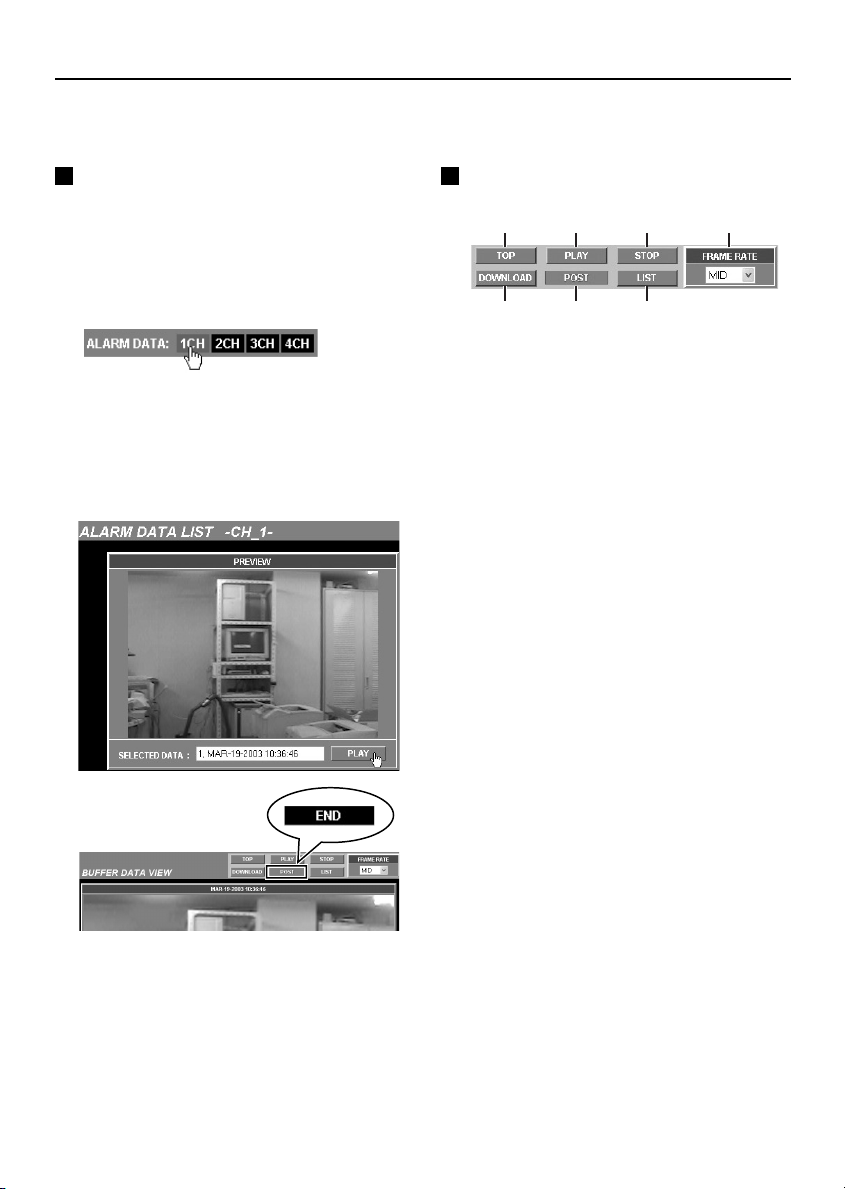
Playing Back Alarm Data
Alarm detection data (when an external sensor or motion detector have been set) and alarm image data
is automatically recorded. Moreover, this data is also played back in the live image screen.
Playing Back Alarm Data in the
Video server’s Internal Memory
1
Click the ALARM DATA indicator.
The ALARM DATA LIST screen will be
displayed, and an alarm image will be
displayed as a still image in the PREVIEW
screen for the selected channel.
2
Click the [PLAY] button.
The BUFFER DATA VIEW screen will be
displayed (the PRE or POST indicator will
illuminate) and playback of the alarm images
will start. When playback is finished, the
[POST] indicator will change to [END].
3
Click the [MULTI VIEW] menu select
button.
The screen will return to the live image
screen.
Descriptions of Alarm Operation
Buttons
1 2 3 4
567
[TOP] button
1
Playback returns to the beginning of the alarm
data that is being played back and then waits in
playback standby. You can then click the [PLAY]
button to play back the data.
[PLAY] button
2
Click this button during playback standby or
when playback is paused to start playback.
[STOP] button
3
If you click this button while playback is in
progress, playback will stop.
FRAME RATE
4
You can select the playback speed for alarm
images using the drop-down list box. If you
change the speed while alarm images are in the
process of being played back, playback will start
again at the selected speed from the beginning
of the data.
Available settings: BASIC, MID, HIGH
Note: The actual playback speed will vary
depending on the alarm data volume and
the network status.
[DOWNLOAD] button
5
Use this button to store alarm data on the
computer.
PRE/POST/END indicators
6
When alarm data is played back, this
automatically appears as [PRE] (during
pre-alarm image playback) or [POST] (during
post-alarm image playback). When playback is
finished, it changes to [END]. If there are no
pre-alarm images, playback starts from the
post-alarm images.
[LIST] button
7
Click this button to switch to the ALARM DATA
LIST screen.
English
– 39 –

Playing Back Alarm Data
Playing Back Expansion Memory
Card Images
1
Click the ALARM DATA indicator while it
is red or green.
The ALARM DATA LIST screen will be
displayed, and an alarm image will be
displayed in the PREVIEW screen for the
selected channel.
1
Playing Back Alarm Images
Stored in a Computer
Refer to p. 44 for details on saving alarm data
into a computer.
1
Using Windows Explorer, click on the
download destination and then
double-click the “Download” folder.
2
Double-click the “alm_viewer_XXXX.html”
file.
The saved alarm data will be displayed as a
still image.
3
Click the [PLAY] button.
Playback will start. When playback is
finished, the [POST] indicator will change to
[END].
2
2
Click on the alarm data to be played back,
and then click the [PLAY] button.
The filename of the selected alarm data will
be displayed in the SELECTED DATA box,
and the message “THE UNIT IS LOADING
ALARM DATA.” will appear briefly. When
loading is complete, the BUFFER DATA
VIEW screen will be displayed (the [PRE] or
[POST] indicator will illuminate) and playback
of the alarm images will start automatically.
When playback is finished, the [END]
indicator will be displayed.
– 40 –
English

Playing Back Alarm Data
Descriptions of Alarm Operation Buttons for Saving Data to a Computer
1 2 3
4 5 6 7 8 9 F
RESOLUTION
1
This lets you change the resolution of the
images.
(Selection screen example)
160x120
320x240
640x480
720x240
720x480
FRAME RATE
2
This sets the transmission speed for images.
Available settings: BASIC, MID 1, MID 2,
IMAGE No.
3
This shows the image number.
The image number changes depending on
the playback status.
[TOP]
4
Displays the first image in the data and also
displays the first image number.
[PREVIOUS]
5
Reverses playback one frame at a time.
MID 3, HIGH
[REVERSE]
6
Reverses playback.
[STOP]
7
If clicked while playback is in progress,
playback stops.
[PLAY]
8
Starts playback.
[NEXT]
9
Carries out playback one frame at a time.
[END]
F
Displays the last image in the data.
English
– 41 –

Playing Back Alarm Data
Alarm Data Deleting
1
Click the ALARM DATA indicator while it
is red or green.
The ALARM DATA LIST screen for the
selected channel will be displayed.
2
Click the check boxes to select the alarm
data to be deleted, and then click the
[DELETE] button.
The alarm data delete confirmation dialog
box will be displayed.
3
Click the [OK] button.
The alarm data will be deleted.
Note: When deleting more than one set of alarm
data at the same time, the message “THE
UNIT IS REMOVING ALARM DATA.” will
be displayed briefly, and then the selected
alarm data will be deleted and the screen
will return to the live image screen.
– 42 –
English

Saving Live Images and Alarm Images
Saving Live Images onto a
Computer
The camera images that are being monitored
can be saved as still images in the computer’s
storage area in JPEG2000 format.
1
Right-click the mouse on the image to be
saved.
The images will be paused and an image
save pop-up menu will be displayed.
2
Click “Save JPEG2000 File As (S)...”.
The Saving JPEG2000 dialog box will be
displayed.
3
Type in the file name and then click the
[Save] button.
The image will be saved onto the computer.
Saving Alarm Images onto a
Computer as Still Images
Alarm images can be saved as still images in the
computer’s storage area in JPEG2000 format.
1
Right-click the mouse on the alarm image
to be saved.
The images will be paused and an image
save pop-up menu will be displayed.
2
Click “Save JPEG2000 File As (S)...”.
The Saving JPEG2000 dialog box will be
displayed.
3
Type in the file name and then click the
[Save] button.
The image will be saved onto the computer.
To check the saved file, check that the
JPEG2000 plug-in has been installed, and
then use Internet Explorer to view the image.
Note:
When saving images into a computer, the
•
images will be saved at the selected
resolution.
The extension used for the saved images will
•
be “.jp2”.
To check the saved file, check that the
JPEG2000 plug-in has been installed, and
then use Internet Explorer to view the image.
Note:
When saving images into a computer, the
•
images will be saved at the selected
resolution.
The extension used for the saved images will
•
be “.jp2”.
English
– 43 –

Saving Live Images and Alarm Images
Saving Alarm Data in Internal Memory onto a Computer
1
Click the ALARM DATA indicator while it
is red or green.
The ALARM DATA LIST screen for the
selected channel will be displayed, and an
alarm image will be displayed as a still image
in the PREVIEW screen.
2
Click the [PLAY] button.
A message will be displayed while the alarm
data is being downloaded, and the alarm
playback screen will be displayed.
3
Click the [DOWNLOAD] button.
A message will be displayed while the alarm
data is being downloaded.
5
Specify the saving destination and the
filename, and then click the [Save] button.
The download will then start.
Do not click in the network video server
screen.
6
Using Windows Explorer, click on the
download destination and then
double-click the “alm_viewer_XXXX.html”
file.
The download will start. When the download
is finished, a message will be displayed.
When this happens, click the [OK] button.
4
When the File Download pop-up menu is
displayed, click [Save].
The Save As dialog box will be displayed.
– 44 –
When you double-click the saved
“alm_viewer_XXXX.html” file, the playback
screen will be displayed. See p. 40 for details
on playing back saved alarm data.
English

WIRELESS LAN SET Settings
Make the wireless LAN settings in the following order.
1
Video server wired LAN settings (TCP/IP settings)
Make sure that the settings in “Network Video Server
Settings” (p. 9) have been carried out.
Computer
Video server
POWER
2
Wireless LAN device settings (TCP/IP settings)
Refer to the documentation that is provided with the wireless
LAN device for details. The ESS ID, transmission mode and
WEP (encipherment) settings are necessary in order to
complete the video server’s wireless LAN settings. Take note
of the settings made.
3
Video server wireless LAN settings (TCP/IP settings)
Use the same ESS ID, transmission mode and WEP
•
(encipherment) settings for the video server’s wireless LAN
settings as were made for the wireless LAN device. (p. 46)
Insert the wireless LAN card into the video server (Figure 1)
(1) Insert a commercially-available wireless LAN card into the
video server so that it is facing in the right direction, and
the card will lock in place.
(2) Press the PC card removal button (A) to release the lock,
and then remove the wireless LAN card.
Note:
It is recommended that you use one of the following
•
commercially-available wireless LAN devices that have
been tested by SANYO. In addition, consult your local
dealer for advice on purchasing a wireless LAN card.
Corega : PCCB-11, PCCL-11
ICOM : SL-11, SL-12
Z-Com : XI-325
When a wireless LAN card as been inserted into the
•
network video server, the video server should be used in
an ambient temperature that does not exceed 40°C.
Computer
Computer
Computer
Access point
Video server
POWER
Figure 1
(A)
Access point
4
Wireless LAN device settings (TCP/IP settings)
When the settings have been completed, the images from the
video server will be transmitted via the wireless LAN device
and can be viewed on the computer as live images.
English
– 45 –
POWER
Video server

WIRELESS LAN SET Settings
Video Server Wireless LAN Settings
Make these settings after steps 1 and 2 have been completed.
2
✱
3
✱
4
5
1
Click the [WIRELESS LAN] menu select
button.
The WIRELESS LAN SET screen will be
displayed.
2
Select “USE” from the [WIRELESS LAN
USE] drop-down list box.
If the wireless LAN card has been inserted,
the items marked with ✱ will automatically
show details for the inserted card.
3
Type in the same ESS ID that was set for
the wireless LAN device.
The ESS ID can consist of up to 23
alphanumeric characters.
– 46 –
4
Set the encipherment method.
Because the video server and the wireless
LAN device communicate by means of radio
waves, there is the possibility that wireless
packets could be intercepted and decoded by
outsiders. It is recommended that you
complete the encipherment setting in order to
provide greater security. (p. 47)
5
Make the TCP/IP settings.
Obtain the IP address and other information
from your network systems administrator.
6
Click the [SET] button and then turn off
the power.
Now make the settings in step 4 (wireless
LAN device settings (p. 45)).
English

WIRELESS LAN SET Settings
Description of WIRELESS LAN
SET Screen
1
2
3
4
CURRENT CHANNEL
1
The transmission mode (frequency channel) that
was set for the wireless LAN device (access
point) will be displayed here automatically.
ESS ID (Extended Service Set-Identifier)
2
This is a verification code for transmissions sent
over the wireless LAN from the video server to
the wireless LAN device.
WEP ENCIPHERMENT (Default setting:
3
DISABLE)
This is a security function that encrypts the data
being transmitted so that it cannot be intercepted
by an unauthorized third party.
Available settings:
DISABLE: Encipherment is not used.
•
WEP40: The encryption key uses 40 bit
•
(64 bit) data.
WEP128: The encryption key uses 128 bit
•
data.
128 bit encipherment provides a higher level
*
of security.
WEP: Wired Equivalent Privacy
*
ENCRYPTION KEY
4
Up to four types of encryption key can be set.
Rules for encryption key entry:
WEP40: The encryption key can consist of
•
up to 5 alphanumeric characters.
WEP128: The encryption key can consist of
•
up to 13 alphanumeric characters.
Encipherment Settings
If you do not type in the same encryption key
that has been set for the wireless LAN device,
communication will not be possible. Make a note
of the encryption key and type it in.
Example: Encryption key 1: 1234567890000
1
2
3
4
5
Note:
•
•
Encryption key 2: 12345
Encryption key 3: ABCDE12345678
Encryption key 4: ABCDE
If using encryption key 1 (or 3), select
“WEP128” from the drop-down list box.
Click encryption key “1”.
If using encryption key 2 (or 4), select
“WEP40” from the drop-down list box.
Click encryption key “2”.
Click the [SET] button.
ESS ID and the encryption key for the video
server and the wireless LAN device will be
verified.
If you are not using encipherment, set “WEP
ENCIPHERMENT” to “DISABLE”.
If you do not type in an encryption key, the
encryption key numbers cannot be selected.
English
– 47 –

PPP (Dial-up) Settings
These settings are used in order to connect the video server to the Internet via a modem.
The PPP settings require you to use the separately-sold Network Archiving Software.
Connecting the Video Server and Installing the Software
1
Video server wired LAN settings (TCP/IP
settings)
Make sure that the settings in “Network
Video Server Settings” (p. 9) have been
carried out.
2
Connect a serial cable between the
RS-232C terminal at the rear of the video
server and a modem.
Internet
Set pin 2 to
VIDEO 2
A1234
COMCOM
“MODEM”
12
12
ON
TERMI
RS485
B AB
OUT
IN
VIDEO 3
PC
MODEM
PC
MODEM
ETHERNET ALL RESET
IN OUT
VIDEO 4
Modem
Serial cable
ALARM
ALARM
IN
GND
12VDC
3
Set pin 2 of the PC/MODEM select switch
IN OUT
VIDEO 1
OUT
RS-232C
IN OUT
at the rear of the video server to the
“MODEM” setting.
Note: After moving the select switch, be sure to
turn the power off and then back on again.
4
Video server PPP settings
Make the settings for transmitting alarm data.
Refer to “Video Server PPP Settings”
(p. 50) for details.
Note: After making the PPP settings, close the
video server setting screen.
5
Install the Network Archiving Software
onto the computer.
Note: After installing the software, close the
software window.
6
Make the Camset settings.
Camset only makes the settings that are
required for setting up the video server. Refer
to the documentation for the Network
Archiving Software for further details.
Click the Camset icon on the desktop.
1
When Camset is opened for the first time, no
files have yet been created, so the following
message will be displayed. Click the [OK]
button. “CAMSET MAIN” will then be
displayed.
– 48 –
English

PPP (Dial-up) Settings
3
24
Set “CONNECT” to “N”.
2
Click the [CAMERA SET] and [RECORD
3
MODE SET] buttons and make the
respective settings.
Click the [LOCAL SERVER SET] button.
4
The LOCAL SERVER SET screen will be
displayed.
LOCAL SERVER USE: Set to “USE”.
•
LOCAL SERVER IP ADDRESS:
•
Obtain the global IP address from the
Internet service provider and type that in.
FTP PORT NUMBER: Type in “21”.
•
FTP PASSIVE: Set to “NO USE”.
•
CAMERA-ID: Type in a unique
•
4-character camera name.
5
6
Click the [SET TO CAMERA] button.
5
The settings will be loaded into the video
server.
Click the [SAVE INFO FILE] button.
6
The settings will be applied to the Network
Archiving Software.
Close the Camset window.
7
Note:
The video server cannot be accessed using
•
the computer’s web browser while the video
server is connected to the modem. Use a
wired LAN or wireless LAN to access the
video server.
Only alarm image data and alarm data can
•
be transmitted by means of PPP connections.
English
– 49 –

PPP (Dial-up) Settings
Video Server PPP Settings
1
Click the [PPP] menu select button.
The PPP SET screen will be displayed.
2
Select “USE” from the [PPP USE]
drop-down list box.
3
Set the following items for connecting to
the access point.
PROVIDER TEL. NO.:
•
If you need to dial “0” first, type in the
number as “0-XXX”.
LOGIN ID: Type in your user ID for the
•
provider.
PASSWORD: Type in your password for
•
the provider.
4
Select the authentication settings
(AUTHENTICATION).
This sets the verification protocol to be used
when connecting to the access point. Set this
to the protocol specified by the Internet
Service Provider. It should normally be set to
“AUTO”.
Available settings:
AUTO (default setting): PAP or CHAP is
•
chosen automatically as required
PAP: Only PAP verification is used.
•
CHAP: Only CHAP verification is used.
•
6
Type in any AT commands that are
required to control the modem.
Type in “AT” at the beginning, and then type
33
in the commands specified by the modem
manufacturer followed by a command to
change flow control to software control.
7
Make the following settings if required.
BAUD RATE: Normally “115200 bps”
•
DATA SIZE: Normally “8 bits”
•
PARITY: Normally “NONE”
•
STOP BIT: Normally “1”
•
8
IP address and error display
1
AUTO IP ADDRESS: The IP address is
only displayed while the video server is
connected.
2
ERROR INFO.: Shows the most recent
error information during a PPP connection.
Display details:
Modem timeout or Not connected
•
Line connection error
•
Line disconnected
•
PPP connection error
•
PPP authentication error
•
PPP connected and disconnected normally
•
5
Select the type of telephone line (CIRCUIT
TYPE).
This sets the type of telephone circuit that the
modem is connecting to.
Available settings:
TONE: For tone dialing circuits
•
PULSE: For pulse dialing circuits
•
Note: Set to “TONE” if using a terminal adapter.
– 50 –
9
Once you have finished changing the
settings, click the [SET] button.
English
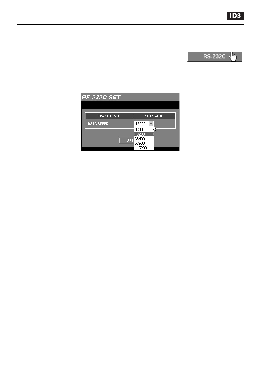
RS-232C Settings (RS-232C SET)
This sets the communication speed for the RS-232C connector of the video server when the video
server is connected to a computer for maintenance and servicing.
Click the [RS-232C] menu select button.
The RS-232C SET screen will be displayed. Select the communication
speed from the drop-down list box, and then click the [SET] button. The
setting will then be saved.
The default setting for the communication speed is 19200 bps.
•
Available settings: 9600, 19200, 38400, 57600, 115200
Note: If you click the [MULTI VIEW] button, the display will return to the live image screen.
English
– 51 –

SSP Settings (RS-485)
Connect the RS-485 connector of the video server and a device with an
SSP communication function. The various input channels (CAM, MPX,
VCR, DVR) can then be operated by remote control via the network.
2
3
4
5
67
1
Click the [SSP] menu select button.
The SSP SET screen will be displayed.
2
Set “SSP CONTROL” to “ON”.
Devices that are equipped with SSP can then
be operated by remote control.
3
Select OWN ADDRESS.
Set the address of the video server to a
number from 1 to 4. The default setting is “4”.
4
Select DATA SPEED.
Select the communication speed from the
drop-down list box.
Available settings:
9600, 19200, 38400, 57600, 115200 (bps)
•
5
Select the SSP control panel position.
Select the operation position from the
drop-down list box. If you select “POP UP”,
the control panel will be displayed in a
separate window when single-screen images
are being displayed.
Available settings:
FIXED, POP UP
•
6
Select the “CATEGORY” setting for each
channel.
The available categories are as shown below.
CAM: Camera
•
MPX: Multiplexer
•
VCR: Time Lapse Video Cassette
•
•
7
Select the “ADDRESS” settings for each
channel.
Set the addresses to a number from 0 to 127.
8
When the settings are complete, click the
[SET] button.
9
Click the [SINGLE VIEW] button.
The live image screen (single screen) and
the control panel for devices that are
equipped with SSP will be displayed, and
remote control operations can be carried out
using the various buttons displayed. Refer to
the documentation for the connected devices
for details on operating methods.
Recorder
DVR: Digital video recorder
– 52 –
English

SSP Settings (RS-485)
Control Panel Displays for Equipment with SSP
2
1
3
5
4
6 7
(CAM) (MPX) (VCR) (DVR)
INDIVIDUAL
1
Select this when operating the connected
devices individually.
GROUP
2
Select this when using a separate system
controller to make group settings.
CATEGORY
3
Use this to select the devices (example: CAM) to
be operated. When a CATEGORY is selected,
the “KEY” display also changes to the display for
the same unit (example: CAM).
You can then operate cameras that are
•
connected to the multiplexer. (Figure 1)
ADDRESS
4
Use this to select the addresses of the
connected devices.
KEY
5
Select this when operating a camera that is
connected to a multiplexer, for example when
CATEGORY is set to “MPX”.
At this time, the control panel changes to the
camera control panel, and the camera can then
be operated.
MULTI VIEW button
6
Click this button to close the SSP operating
screen. The display will return to the 4-screen
split screen.
POP UP button
7
This will be displayed when “CONTROL PANEL
DISPLAY” is set to “FIXED”. You can click this
button to display the control panel in a separate
window.
English
Figure 1
– 53 –

SSP Settings (RS-485)
Connection Examples for Equipment with SSP
(Dome Camera)
Turn off the power supply for all equipment, and
then use twisted pair cables to connect the
devices that are equipped with an RS-485
control connector to the video server.
Computer
ALARM
IN
GND
12VDC
Camera A
1
Make the following connections.
Camera A: Connect a normal CCD camera
to VIDEO IN 1 and 2.
Camera B: Connect a dome camera with
SSP function to VIDEO IN 3 and 4.
2
Click the [SINGLE VIEW] menu select
button.
The control panel for equipment with SSP
function will be displayed.
3
Set “CATEGORY” to “CAM”.
While looking at the images from camera B
that are being transmitted via the network,
click the CAM buttons to pan and tilt the
dome camera.
Note:
Camera A is for monitoring images only; it
cannot be operated using the CAM buttons.
IN OUT
VIDEO 1
ALARM
OUT
PC
12
MODEM
ON
RS-232C
IN OUT
VIDEO 2
TERMI
A1234
COMCOM
RS485
B AB
IN
VIDEO 3
OUT
ETHERNET ALL RESET
IN OUT
VIDEO 4
Camera B
Note:
The twisted pair cables should always have signal A
•
connected to signal A, and signal B connected to
signal B, and the ground should always be
connected too.
If more than one device is connected, enable the
•
termination settings for the devices at both ends of
the series. Set communication/terminal select switch
1 at the rear of the video server to the “ON” position,
and set the termination switch for the last device in
the series to “ON”. All other devices should have the
termination settings set to “OFF”.
3
Monitor TV
– 54 –
English

LANGUAGE Selection
Click the [LANGUAGE] menu select button.
The language selection screen will then be displayed. Once a language is
selected, the language setting is stored in memory, so the language
selection screen is not displayed the next times you access the video server.
STATUS Checking
This displays information about the video server status.
Click the [STATUS] menu select button.
The STATUS screen will be displayed.
Note: If you click the [MULTI VIEW] button, the display will return to the live image screen.
1
2
3
4
FIRMWARE VERSION
1
This shows the version number for the video server’s firmware.
SUB-MICROCOMPUTER VERSION
2
This shows the version number for the video server’s sub-microcomputer.
PCMCIA: SOCKET STATUS
3
This shows the usage status for the PC card slot.
VIDEO INCOMING SIGNAL TYPE
4
This shows the type of video input signal that is being received (NTSC or PAL).
English
– 55 –

Glossary of Terms
Cookie
A system whereby a computer (HTTP server)
that hosts web pages sends information that is
stored by a user’s computer, so that when that
user visits the same web page a second time,
the information that has been automatically
saved is transmitted back to the HTTP server.
For example, it assigns a unique number to the
information from a user and remembers part of
the information that the user has entered, so that
next time the user accesses the web page, the
same information does not need to be entered
all over again.
Ethernet
There are a variety of different types of computer
network. Ethernet is a type of network that was
developed by Xerox Corporation.
Firewall
A firewall is like a barrier between an outside
network (the Internet) and a local network (LAN).
It is a security measure that is used to prevent
unauthorized access to information by outsiders.
Firmware
Software that is used to operate a device.
Frame rate
This is an indication of how many times an
image is refreshed in a single second when
images are being displayed or moving images
are being played back. If the value (fps) is large,
the rate at which images are refreshed is faster,
but this setting is a theoretical maximum value,
and so if the images are complex, the images
may be refreshed even more slowly. The set
frame rate may not be attained for other reasons
also, such as the image loading time and the
performance of the computer being used.
FTP (File Transfer Protocol)
A protocol (communication standard) for
transmitting files via the Internet. This
communication protocol allows files and data to
be transferred via the Web, whereas previously it
was only possible using e-mail.
Hard disk
A storage device for large quantities of data that
is used by equipment such as computers. It
contains a flat disc that is coated with magnetic
particles, and this disc spins around and a
magnetized head is used to read the data stored
on the disc. The data can be read at extremely
fast speeds, giving it excellent data searching
performance.
HTML file
An HTML file is a text file that is written in the
HTML language (a language that is mainly used
to create web pages). The file extensions used
are .htm and .html.
IP address
A code that allocates “addresses” for each
individual computer and other device on the
Internet or in a network. Devices that
communicate by IP all must have an IP address
assigned to them. Devices that are connected to
the Internet are assigned a unique global IP
address so that no two devices have the same
address. IP addresses consist of a network ID
and a host ID, and the network ID identifies the
address as Class A, B or C.
JPEG2000 (Joint Photographic Experts
Group)
An image file compression standard that was
formulated by the International Organization for
Standardization (ISO). It provides higher
compression ratios and higher quality than
conventional JPEG.
LAN (Local Area Network)
A computer network that is located within a
relatively small area, such as a single floor of a
company building.
– 56 –
English

Glossary of Terms
MAC address (Media Access Control
address)
A 12-digit hexadecimal identification number that
is assigned to LAN cards and LAN boards in a
computer. Complex device arrangements may
use IP addresses, but whereas IP addresses are
assigned as required by a network system
administrator, MAC addresses are burned into
the LAN card at the time of manufacture.
Ethernet uses the MAC address as the basis for
transmission of data.
Memory
A memory device is a semiconductor device that
stores digital data in units of single bits (binary
digits) that consist of either 0s or 1s.
Modem
A device that converts between analog signals
(from telephone lines) and digital signals (such
as from computers).
Network
A variety of computers and other devices that
are connected together by means of cables
(wired) or via a wireless LAN so that they can
exchange data with each other.
Port number
This is a number that is used to identify
applications on the Internet. For example, SMTP
for e-mail is normally 25 and HTTP (web-related
software) is usually 80.
PPP (Point to Point Protocol)
A protocol (communication standard) that
determines the process by which two points
(computers) are connected across a network
using telephone lines.
Resolution
This indicates the quality of images. The
numbers represent the degree of detail for the
images during printing or displaying, and the
units used are “dpi” (dots per inch).
Router
A device that connects one network to another
network. It looks up IP addresses for network
devices and determines what route should be
used for the information to be transmitted to and
from these devices.
SMTP (Simple Mail Transfer Protocol)
A protocol (communication standard) for sending
and receiving electronic mail via the Internet and
Intranets. It controls the flow of mail between
servers and is also used when clients send mail.
Stop bit
A symbol that is added at the end of a byte of
data (8 bits) during data transmission to indicate
the end of that byte.
Subnet mask
An IP address consists of a network ID and a
host ID. A subnet mask is used to mask part of
an IP address in order to specify whether the IP
address is on a local or a remote network.
TCP/IP (Transmission Control
Protocol/Internet Protocol)
A network protocol (communication standard)
that was developed by the Network Project that
was funded by the United States Department of
Defense. It can be thought of as the
communication technology that makes it
possible to send and receive data over the
Internet. Computers that are connected via the
Internet use this protocol, and it works
regardless of the type of device. Basically IP
controls the sending of data in separate blocks
called “packets”, and TCP receives these
packets, opens them to look at their contents,
and then puts all of them back together into one.
URL (Uniform Resource Locator)
A method of specifying a resource on the
Internet. An example of an URL that is used to
access a website on the Internet is
“http://www.sanyo.com/”.
Web browser
Software that is used to view web pages. The
two most commonly-used web browsers are
Microsoft Internet Explorer and Netscape
navigator from Netscape Communications.
English
– 57 –

Glossary of Terms
Pre-alarm and post-alarm recording
Pre-alarm and post-alarm recording involve
recording data according to a selected ratio in
the video server’s internal memory. The default
ratio is pre-alarm = 0 / post-alarm = 10. When an
alarm is detected in this condition, only
post-alarm images are recorded in the video
server’s internal memory.
Post-alarm recording is the recording of alarm
data after an alarm has been detected by an
external sensor or motion detector. When an
alarm is detected, the alarm data is recorded into
the internal memory according to the ratio
selected. If the ratio is 0/10, all of the available
memory space is devoted to post-alarm
recording.
Pre-alarm recording sequentially records alarm
images from immediately before the alarm was
detected according to the ratio selected. When
an alarm is detected, images from before the
alarm that fall within the amount specified by the
ratio selected are recorded in the pre-alarm area
of the internal memory.
For example, if the alarm recording area of the
internal memory is set to a ratio of 3/7, 30% of
the available area is devoted to recording
images from immediately before the alarm is
detected. Actual alarm images are then recorded
in the remaining 70%, and the pre-alarm and
post-alarm recordings are treated as a single
alarm event.
When alarm images are played back, the images
can be viewed continuously starting from the first
images recorded immediately before the alarm
was detected. The alarm recording area ratio is
an important point for consideration when
making settings.
(Alarm input)
Post-alarm recording area (10)
(Internal memory: approx. 16 MB)
(Alarm input)
Pre-alarm
recording
area (3)
Post-alarm recording area (7)
(Internal memory: approx. 16 MB)
– 58 –
English

Troubleshooting
If the video server cannot be
connected
If the live image screen does not appear when
you type the video server’s IP address into the
location bar of the web browser, check the
following items.
Is the Ethernet cable connected correctly?
•
If the cable is not connected correctly, the link
indicator at the rear of the video server will not
be illuminated. Check the cable connection.
Note:
Cross-type and straight-type Ethernet cables are
available. To connect the video server directly to
a computer, you need to use a cross-type cable.
Is the link indicator flashing?
•
If the link indicator is illuminated steadily, it
means that the cable is connected to the video
server but communication is not possible.
The default network settings for the video server
are as follows.
IP address: 192.168.0.2
•
Subnet mask: 255.255.255.0
•
Gateway: 192.168.0.1
•
Port number: 80
•
If you forget the IP Address
If you forget the video server’s IP address, you
can check it using the following procedure.
1
Set pin 2 of the communication/terminal
select switch at the rear of the video
server to the “MODEM” setting, turn off
the video server’s power, wait three
seconds or more and then turn the power
back on.
2
Set pin 2 of the communication/terminal
select switch at the rear of the video
server to the “PC” setting, turn off the
video server’s power, wait three seconds
or more and then turn the power back on.
4
Start the web browser and point it to
“http://192.168.0.2/”.
5
Check the network settings. (p. 18)
6
Turn off the video server’s power.
7
Return the computer’s IP address to its
original setting.
Note:
If the password for the Administrator level ID has
•
been changed, be careful not to forget the password.
Check that none of the other devices that are
•
connected to the network have a duplicate IP
address of “192.168.0.2”.
3
Set the computer’s IP address to
“192.168.0.✱”.
Enter a spare number that is 3 or greater as
the host address.
English
– 59 –

Specifications
Alarm input/output
Input : 4 (Normal open: Non-voltage make contact; Normal
•
Output : 1 (Motion detector and external input AND/OR output
•
Resolution : 720 x 480, 720 x 240, 640 x 480, 320 x 240,
Compression method : JPEG2000
Picture quality (compression ratio) : BASIC (Rough), MID 1 (low), MID 2 (medium),
Image transfer speed : Max. 30 fps (640 x 480 pixels)
VIDEO IN/OUT terminals : VS/VBS, 1.0 Vp-p/75 Ω, BNC connector (4 pairs)
Other functions : Color/Black & white selectable, built-in clock function
Interfaces
Ethernet connector : 10/100 Base-T (RJ-45)
•
RS-232C connector : D-Sub 9-pin
•
PC card slot : PCMCIA Type II (5 V power supply only)
•
Pre-/post-alarm buffer : 16 MB
Protocols : TCP/IP, PPP, FTP, HTTP
Software : Plug-in browser (Internet Explorer Ver. 5.5 SP2 or
Clock backup : 8 hours
Operating conditions
Temperature : –10 ~ +50°C
•
Humidity : 90% R.H. or less
•
Power supply : DC 12 V
Power consumption :5.5 W
Weight : Approx. 970 g
Dimensions
close: Non-voltage break contact)
function, open collector: Max. 25 V 200 mA)
160 x 120 pixel
MID 3 (high), HIGH (maximum)
later or equivalent)
206 mm
44 mm
Appearance and specifications are subject to change for improvement without notice.
175 mm
– 60 –
English


Printed on recycled paper
1AC6P1P2600-A
L8NAA/XE (0503KP-CZ)
SANYO Electric Co., Ltd.
Printed in Japan
 Loading...