

Sanyo VSP-RV200 Instruction Manual
INSTRUCTION MANUAL
Receiver Unit
VSP-RV200
CONTENTS
FEATURES
SAFETY PRECAUTIONS .......................... 2
PART NAMES............................................ 3
CONNECTIONS ......................................... 6
ADDRESS AND COMMUNICATION
SPEED SETTINGS..................................... 7
LIST OF COMMANDS ............................... 7
SPECIFICATIONS...................................... 8
• Pan/tilt driver and zoom lens can be operated using
an SSP controller
• The unit can be waterproofed to make it suitable for
outdoor installation
• The pan/tilt driver can run on any one of three
different power supply voltages (230 V/110 V/24 V)
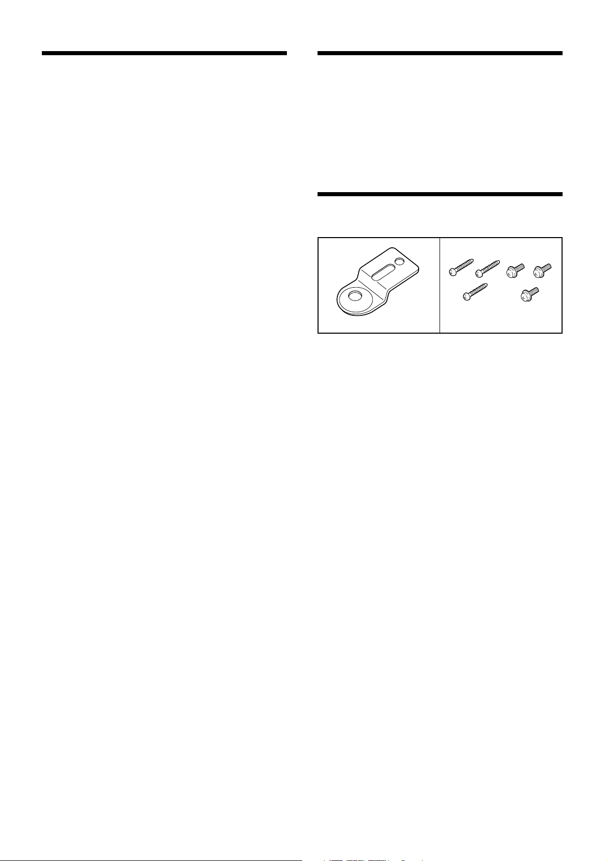
ACCESSORIES
Mounting brackets Screws
• Fixer ............................. x5
This fixer is used for internal wiring.
– 1 –
SAFETY PRECAUTIONS
In case of problem
Do not use the unit if smoke or a strange odour comes from
the unit, or if it seems not to function correctly. Disconnect
the power cord immediately, and consult your dealer (or a
Sanyo Authorized Service Centre).
Do not open or modify
Do not open the cabinet, as it may be dangerous and cause
damage to the unit. For internal settings and repairs, consult
your dealer (or a Sanyo Authorized Service Centre).
Do not put objects inside the unit
Make sure that no metal objects or flammable substance
get inside the camera. If used with a foreign object inside, it
could cause a fire, short-circuits or damages.
If water or a liquid gets inside the unit, disconnect the power
cord immediately, and consult your dealer (or a Sanyo
Authorized Service Centre). Be careful to protect the
camera from rain, sea water, etc.
Be careful when handling the unit
To prevent damages, do not drop the unit or subject it to
strong shock or vibration.
Install away from electric or magnetic fields
If installed close to a TV, radio transmitter, magnet, electric
motor, transformer, audio speakers the magnetic field they
generate will distort the image.
Cleaning
Dirt can be removed from the cabinet by wiping it with a
•
soft cloth. To remove stains, wipe with a soft cloth
moistened with a soft detergent solution and wrung dry,
then wipe dry with dry soft cloth.
Do not use benzine, thinner or other chemical product on
•
the cabinet, as that may cause deformation and paint
peeling. Before using a chemical cloth, make sure to
read all accompanying instructions. Make sure that no
plastic or rubber material comes in contact with the
cabinet for a long period of time, as that may cause
damage or paint peeling.
CAUTION:
Do not install this equipment in a confined space
•
such as a book case or similar unit.
To ensure waterproof, use cable with minimum with
•
diameter 19 mm.
An all-pole mains switch with a contact separation of
•
at least 3 mm in each pole shall be incorporated in
the electrical installation of the building.
Protect from humidity and dust
To prevent damages to the unit, do not install it where there
is greasy smoke or steam, where the dampness may get
too high, or where there is a lot of dust.
Protect from high temperatures
Do not install close to stoves, or other heat generating
devices, such as spotlights, etc., or where it could be
subject to direct sunlight, as that could cause deformation,
discoloration or other damages.
Be careful when installing close to the ceiling, in a kitchen or
boiler room, as the temperature may raise to high levels.
Install where the temperature range will stay between –10°C
and 50°C. (no condensation)
– 2 –
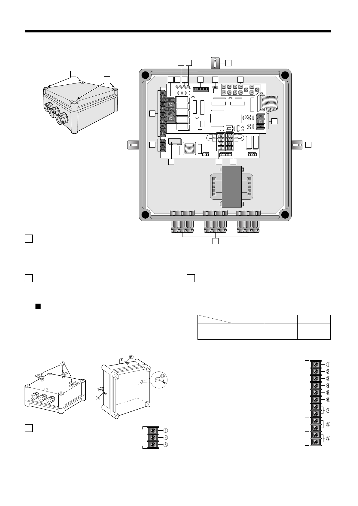
PART NAMES
9
7
2
1
1
2
1 Top cabinet installation screws
Be careful when tightening the installation screws.
Adjust the tightening fit correctly before fully tightening
the installation screws. If the screws are overtightened,
it may damage the screws.
865
4
3
16 15 14
10 11
12
13
2
17
2 Mounting brackets
Use the accessory mounting brackets to install the
receiver unit securely to a wall at three points.
Installing the mounting bracket
Turn the receiver unit upside down, align the
mounting brackets with the three points on the top,
left and right surfaces of the unit, and then secure
the brackets by tightening the screws A (M5 x 8 with
flange). Next, use the accessory screws B to install
the unit to the wall.
3 AC power input
Connect the power supply to this terminal.
Terminal for 230 V AC 50 Hz (Live)
1
Not used (N••••C)
2
Terminal for 230 V AC 50 Hz (Neutral)
3
LIVE N.C
AC POWER INPUT
NEUTRAL
4 General operating terminals
Connect other devices such as a pan/tilt driver, camera
or light to operate them.
Note: If using a pan/tilt driver or camera power, use
currents which are at or below those shown below.
AC 24 V AC 110 V AC 230 V
PAN+TILT 2.0 A 0.44 A 0.22 A
CAMERA 0.5 A 0.11 A 0.05 A
• Pan/tilt driver
UP:
1
Tilts the pan/tilt driver upward using
the controller.
DOWN:
2
Tilts the pan/tilt driver downward using
the controller.
RIGHT:
3
Pans the pan/tilt driver to the right
using the controller.
LEFT:
4
Pans the pan/tilt driver to the left using
the controller.
COMMON:
5
Connect the pan/tilt driver ground.
UP DOWN RIGHT
PAN/TILT DRIVER
LEFT
COMMON AutoPan
OUT OUT OUT OUT INPUT INPUT
CAMERA POW
AUX 1 AUX 1
– 3 –
 Loading...