

Page 1
INSTRUCTION MANUAL
System Controller
VSP-9000
About this manual
• Before installing and using this unit, please read this manual carefully. Be sure to keep it handy for
later reference.
• This manual gives basic connections and operating instructions.
Page 2

Table of Contents
Introduction
Precautions (For UL) ...................................2
Safety Cautions............................................3
Major Characteristics..................................8
Accessories..................................................8
Preparation
Part Names...................................................9
Menu Display..............................................11
System Information...................................12
Sample System Connection .....................13
Connection and Communication
Setup 1 (VIDEO).........................................15
Connection and Communication
Setup 2 (VIDEO).........................................18
Connection and Communication
Setup 3 (VIDEO/TELEMETRY A)...............21
Connection and Communication
Setup 4 (VIDEO/TELEMETRY B)...............24
Connection and Communication
Setup 5 (VIDEO/TELEMETRY A/B) ...........27
Communication Lines and
Number of Connected Units.....................30
Operation
Hard Disk Digital Recorder (DVR)
Operation....................................................32
Multiplexer (MUX) operation .....................36
Dome Camera/Zoom Camera Operation..38
System Setup
System Setup Overview ............................41
Language Selection...................................42
Communication Setup...............................43
b Select a communication item
(COMMUNICATIONS)...................................... 43
b Unit Address Setup........................................... 44
English
Control Setup.............................................47
b Select a Control Item
(ACCEPTED VALUES)..................................... 47
Password Setup (PASSWORD)................50
b AT SWITCHING ON (Power ON password).....51
Setup (CONFIGURATION).........................52
b Initialize (RESTORE BASIS VALUES)............. 53
b Buzzer and menu display setup
(BUZZER/DISPLAY) ........................................ 53
b Joystick Setup (JOYSTICK) ............................. 54
b Touch screen adjustment
(TOUCH SCREEN SETTING).......................... 55
b Touch Screen Initialization and Reset.............. 56
b Touch screen test (TOUCH TEST) .................. 57
Software
Software Configuration.............................59
b Operating Environment .................................... 59
Connection and Software Installation .....60
b Install the Software ........................................... 60
b Making Connections ......................................... 60
System Setup (Setup) ...............................61
A General (General Settings) .............................. 62
B Cameras (Camera communication setup)........ 64
C Monitor/Local Mux
(Valid/Invalid setup for hard disk digital recorder
with multiplexer) ............................................... 66
D Enabling (stopping or starting settings)............ 67
Language Setup (Language) ....................68
b Creating Two Different English Tabs................ 69
Graphics Environment Setup (Maps) ......71
b Display Telephone Number on
Opening Screen ............................................... 72
b Map Screen Explanation .................................. 73
b Sample Equipment Allocation .......................... 76
b Protocol Chart (Autopan).................................. 79
b Protocol Chart (Patrol)...................................... 80
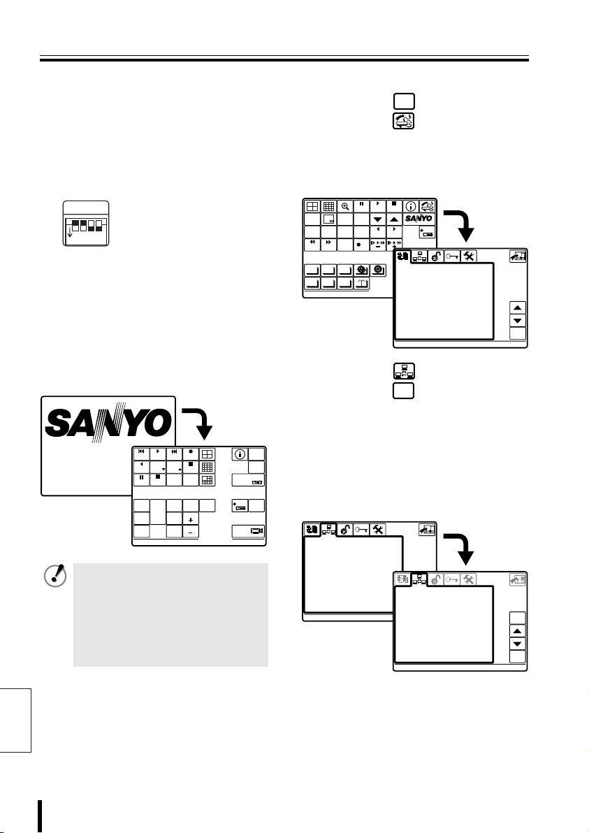
b Changing the Opening screen to “SANYO”...... 81
b Create a map using the graphics tool
and display on opening screen......................... 82
b Basic Graphics ................................................. 84
Others
Specifications............................................85
b Outer Dimensions (Units: mm)......................... 85
Appendix ....................................................86
b Communications Chart ..................................... 86
b Message Chart ................................................. 88
b Special Code Chart .......................................... 89
1 Introduction
Page 3
Precautions (For UL)
CAUTION
RISK OF ELECTRIC SHOCK
DO NOT OPEN
CAUTION:
ELECTRIC SHOCK, DO NOT REMOVE
COVER (OR BACK).
NO USER-SERVICEABLE PARTS INSIDE.
REFER SERVICING TO QUALIFIED
SERVICE PERSONNEL.
WARNING:
electric shock, do not expose this appliance
to rain or moisture.
CAUTION:
expressly approved by the manufacturer may
void the user's authority to operate this
equipment.
TO REDUCE THE RISK OF
To reduce the risk of fire or
Changes or modifications not
The lightning flash with arrowhead
symbol, within an equilateral
triangle, is intended to alert the
user to the presence of
uninsulated “dangerous voltage”
within the product's enclosure that
may be of sufficient magnitude to
constitute a risk of electric shock
to persons.
The exclamation point within an
equilateral triangle is intended to
alert the user to the presence of
important operating and
maintenance (servicing)
instructions in the literature
accompanying the product.
This equipment has been tested and found to
comply with the limits for a Class B digital
device, pursuant to part 15 of the FCC Rules.
These limits are designed to provide
reasonable protection against harmful
interference in a residential installation. This
equipment generated, uses and can radiate
radio frequency energy and, if not installed
and used in accordance with the instructions,
may cause harmful interference to radio
communications. However, there is no
guarantee that interference will not occur in a
particular installation. If this equipment does
cause harmful interference radio or television
reception, which can be determined by turning
the equipment off and on, the user is
encouraged to try to correct the interference
by one or more of the following measures:
• Reorient or relocate the receiving antenna.
• Increase the separation between the
equipment and receiver.
• Connect the equipment into an outlet on a
circuit different from that to which the
receiver is connected.
• Consult the dealer or an experienced radio/
TV technician for help.
For the customers in Canada
This class B digital apparatus complies
with Canadian ICES-003.
SERVICE
This unit is a precision instruments and if
treated with care, will provide years of
satisfactory performance. However, in the
event of a problem, the owner is advised not
to attempt to make repairs or open the
cabinet. Servicing should always be referred
to your dealer or Sanyo Authorized Service
Center.
Introduction 2
English
Page 4

Safety Cautions
Main Unit
WARNING
bbbb Never use when unit emits smoke,
unusual noises, or unusual smells.
Using under these abnormal conditions
can cause fires and electric shock.
Immediately unplug the AC adapter power
plug from the outlet, confirm that the
smoke stops, and then request repairs
from the installer or the purchasing source.
Never attempt to repair the unit on your
own, as this is dangerous.
bbbb Never disassemble or modify
• Touching the internal parts is
dangerous, and can cause fires and
electric shock.
• Request internal inspection, adjustment,
and repairs from the installer or the
location of purchase.
bbbb Never get unit wet
• This unit is not waterproof or dustproof.
Do not install where exposed to rain,
excessive humidity, or excessive dust.
This can cause fires and electric shock.
Do not install in a bath or shower room.
• In the event that water enters the unit
interior, turn OFF power to the unit,
unplug the AC adapter power plug from
the outlet, and contact the installer or
location of purchase. Continued use can
cause fires, electric shock, and unit
breakdowns.
bbbb Do not use during thunderstorms
Do not use this during thunderstorms.
In particular, never touch the AC adapter
or connection cables. This can cause
electric shock.
bbbb Do not install in unstable location
• The unit may fall or topple, causing
injuries or unit breakdowns.
• In the event that the unit is dropped or
the cabinet is broken, turn OFF power to
the unit, unplug the AC adapter power
plug from the outlet, and contact the
installer or location of purchase.
Continued use can cause fires or
electric shock.
bbbb Do not use in locations with explosion
risk
Do not use in locations where flammable
gas or explosive gas may exist in the
atmosphere. This can cause ignition and
explosion.
WARNING
Never put menu display liquid crystal in
your mouth
If the menu display breaks and the liquid
crystal inside has leaked, be careful never
to put it in your mouth. This could cause
poisoning. In the event that it contacts your
mouth or eyes, wash immediately with
water and consult a physician. If it contacts
your hands or clothing, wipe it off with
alcohol etc., and wash it away with water.
English
3 Introduction
Page 5
Safety Cautions
Provided AC Adapter
CAUTION
bbbb Transport with care
Unplug the AC adapter power plug from
the outlet, confirm that connection cables
are disconnected, and transport carefully
to avoid dropping the unit or subjecting it to
severe shock.
bbbb Cautions for care or long-term disuse
Unplug the AC adapter power plug from
the outlet. Caring for the unit with the AC
adapter connected can cause electric
shock.
bbbb Cleaning the interior
For cleaning the interior, consult the
installer or the location of purchase. When
dust has accumulated inside the unit over
time without cleaning, this can cause fires
or unit breakdowns.
bbbb Installation location
This unit is comprised of precision
electronic parts. Never install in the
locations described below, as this can
cause operation errors and unit
breakdowns.
• In direct sunlight
• In extreme humidity or where humidity
fluctuates wildly
• Where water could be splashed
• Near heating/cooling equipment or
humidifiers.
• Where cold air from air conditioners
contact the unit directly
• Where dust is extreme
• Near a spark source
• Near magnetic objects
• Near explosive materials
• Where subject to vibration
DANGER
bbbb Only use with 100 to 240V power source
voltage.
This can cause fires and electric shock.
bbbb Never disassemble or modify
• Touching the internal parts is
dangerous, and can cause fires and
electric shock.
• Never use as a DC power source unit.
bbbb Never get unit wet
• Never submerge in water or get unit wet.
This can cause fires and electric shock.
• Do not use in a bath or shower room.
• In the event that water enters the unit
interior, unplug the power plug from the
outlet, and contact the installer or
location of purchase. Continued use can
cause fires, electric shock, and unit
breakdowns.
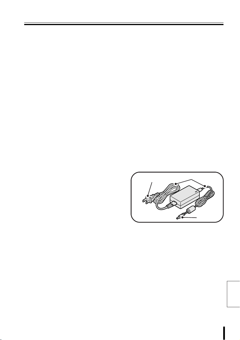
Power plug
AC adapter
Power cord
DC plug
Introduction 4
English
Page 6

Safety Cautions (Continued)
Provided AC Adapter
WARNING
bbbb Use only the provided AC adapter
Use the provided AC adapter. Using a
different AC adapter can cause fires or
electric shock, due to differences in power
cord current capacity.
bbbb Never touch the AC adapter with wet
hands
This can cause electric shock.
bbbb Power plug
Never use while abnormality is not
corrected.
The following situations can cause fires or
electric shock.
• Never allow dust to accumulate on
power plug or in outlet insertion holes.
Dust and dirt on either contact portion
can cause an electric short or
overheating. Wipe off with a dry cloth.
• When using an outlet where humidity is
high or condensation forms easily, or an
outlet in a kitchen or dusty environment,
unplug the power plug regularly and
wipe off the dust and dirt adhering to the
plug.
• Never pull the power cord to unplug the
power plug.
Always hold the power plug when
unplugging.
• Never leave the power plug plugged into
the outlet while the DC plug is
disconnected from the power source
input terminal on this unit. This can
cause electric shock when touching with
wet hands, or when an infant places the
power plug in his/her mouth.
• Never use an outlet if the power plug is
fully seated but is still loose in the outlet.
This can cause fires due to overheating.
• Never use the power plug when it is
English
damaged. When the plug has poor
contact, consult the installer or the
location of purchase.
bbbb Power cord
Never bundle up the power cord during
use. This can cause overheating, fires and
electric shock.
bbbb When using an extension cord
Be careful that the total power
consumption of the connected equipment
does not exceed the rated power of the
extension cord.
Exceeding the rated power can cause
fires.
5 Introduction
Page 7

Safety Cautions
CAUTION
bbbb Do not connect to other equipment
The provided AC adapter is exclusively for
this unit. Connecting to other equipment
can cause fires or electric shock.
bbbb Power cord
Damaging the power cord in the following
manner can cause fires or electric shock.
When the power cord is damaged, consult
the installer or the location of purchase.
• Never place a heavy object on the
power cord, or expose to heating
equipment, heated surfaces (front
surface of heaters), or direct sunlight.
• Do not stress the power cord with the
weight of the AC adapter unit.
• Never bundle up the power cord during
use.
• Never bend, modify, or staple the power
cord.
bbbb Power cord connection
Route the power cord and connecting
cables with care. Tripping over power
cords can cause injuries due to falls or
falling equipment.
bbbb Connect power plug securely to outlet
Using with an incomplete connection can
cause fires due to overheating.
bbbb Do not place in unstable location
Place the unit in a stable location.
Placing the unit in an unstable location can
cause injuries or unit breakdowns, due to
falling or toppling equipment.
bbbb Menu Display
• When used in a cold location, the screen
will initially appear darker than normal.
As the unit internal temperature rises,
the brightness will return to normal.
• The display is a consumable part. When
the screen is darkened, flickering, or not
displaying images, the LED used in the
interior illumination device has expired.
Replace with a new part.
(Approximate service life: About 50,000
hours with the display ON.)
To replace the display, consult the
location of purchase.
• Using a mobile phone within 30cm of
this unit can interfere with the image.
• The display brightness may look
uneven, depending on the display
content.
Safety Cautions for Menu Display
• Never wipe the display with detergents or
liquids containing ammonia.
• When soiled from fingerprints, wipe gently
with a soft cloth. Rubbing harshly with a soft
cloth can cause scratches or display
abnormalities. Also, to protect the screen,
do not wipe with a dry cloth or chemically
treated cloth.
• Do not use gloves with a rough texture.
• The surface is scratched easily. Do not
scrape, hit, or compress with a hard object.
This can cause display unevenness or
breakdowns.
• Do not use scrubbing sponges or sharp
objects on the easily scratched surface of
the display.
• Do not place heavy objects on the screen,
or leave the screen under pressure.
• Do not place a container of water,
chemicals, or small objects in a place where
the display surface could be damaged.
Introduction 6
English
Page 8

Safety Cautions (Continued)
Always Observe These Rules for Proper Use
bbbb Trademark
Brands and product names described in
this document are trademarks or
registered trademarks of their respective
companies.
bbbb When not using for long periods
Unplug the power plug from the outlet.
However, this could damage the functions.
Connect the power and operate the unit
occasionally.
bbbb Fogging (Condensation)
Drops of water form on the outside of a
glass containing very cold water. Similarly,
droplets can form on the interior of this
unit. This is called fogging, or
condensation.
Using the unit during fogging can cause a
unit breakdown.
Be careful of fogging when the
environment temperature changes
suddenly, such as when heating the room
quickly.
Fogging does not occur while electrical
current is present.
When fogging could occur...
Turn OFF the unit power, and leave the
unit in its installed position for one to two
hours before use.
bbbb Caring for the Unit
Unit
Unplug the power plug from the
1
outlet.
Gently wipe away any
2
contamination, using a soft cloth.
When heavily soiled...
Immerse a cloth in neutral
3
detergent thinned with water,
wring it well, and wipe the unit.
Finish with a dry cloth.
Cautions
• Never use benzene or paint thinner to
clean the unit. The unit could discolor, or
paint could be removed.
• When using chemically treated cloths,
note the cautions on the package.
• Do not expose the unit to volatile
chemicals such as pesticides. Do not
leave the unit in contact with rubber or
plastic products for long periods.
The unit could discolor, or paint could be
removed.
English
7 Introduction
Page 9
Major Characteristics
Accessories
• Use joystick for pan/tilt/zoom operations
• Select your language
• Wide-range control of high-speed dome
cameras and receivers
• Automatically test communication
channels
• RS485 communication line
bbbb Security
• Communication errors and warning buzzers
• Three-stage passwords and
keyboard-specific settings available
Startup password:
The password screen is displayed upon
turning on the controller.
Alarm reset password:
The password input screen is displayed
when resetting after a warning appears on
the menu display.
Setup password:
The password input screen is displayed
when changing equipment settings.
Licensed Under U.S. Patent No. 4974088
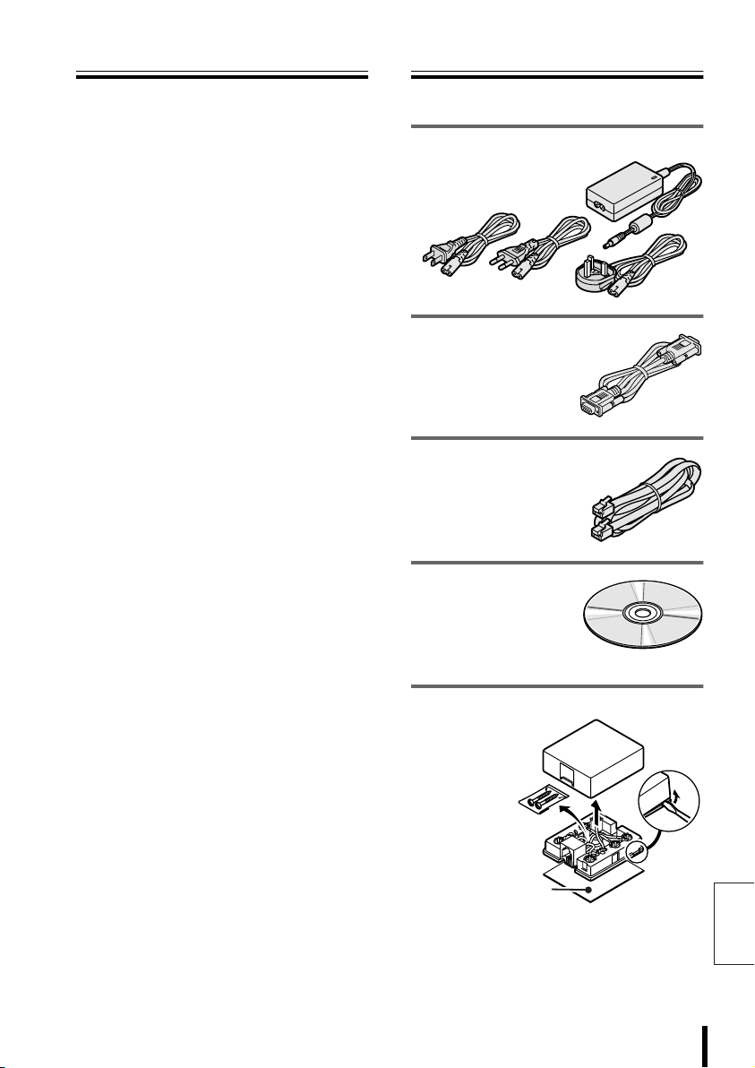
Check that all accessories are included.
AC adapter/power cord x 3
• North America: 1
• Europe: 1
• Great Britain: 1
PC (RS232) connection cable x 1
Modular cable x 6
(Straight type: 150cm)
Software (CD-ROM)
• System Setup
• Language Setup
• Graphics Environment Setup
Communication
conversion
connectors x 6
• Screws x 2
• Double-faced
tape x 1
Double-faced tape
(How to disassemble)
English
Introduction 8
Page 10
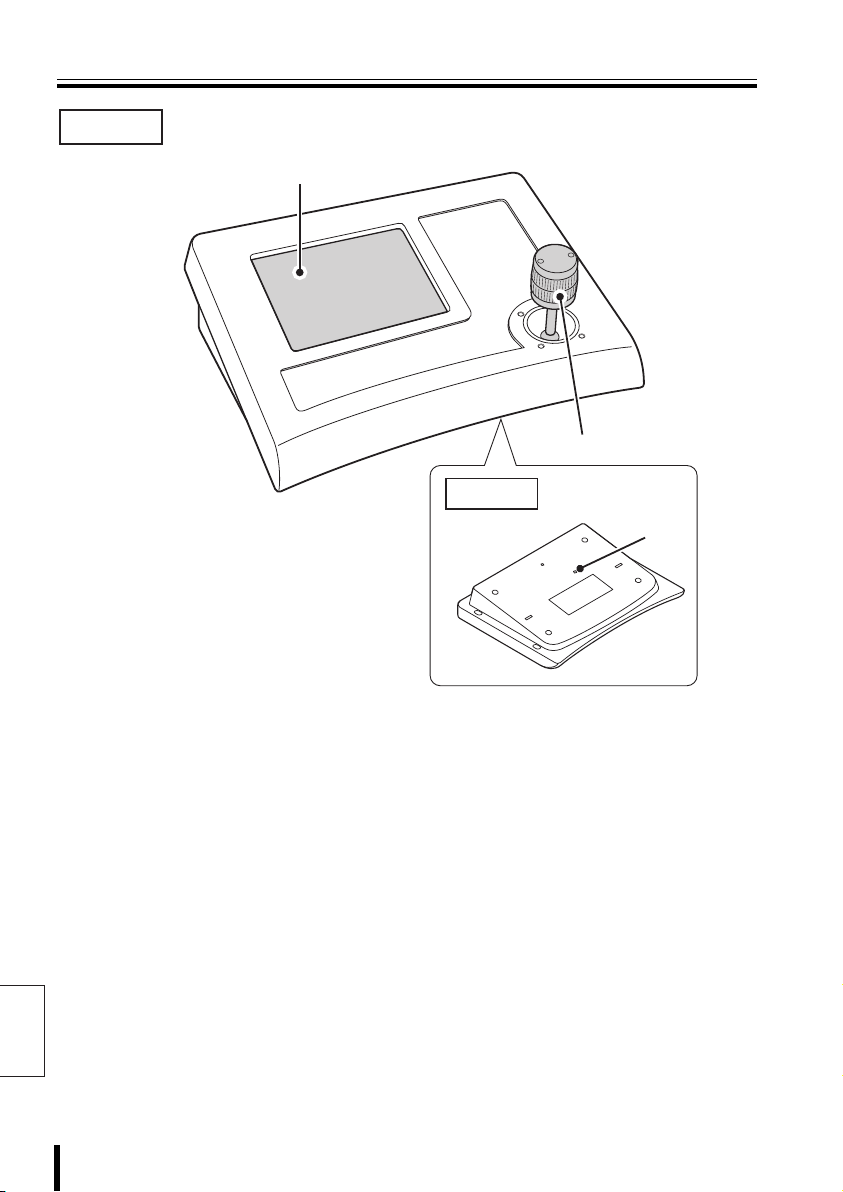
Part Names
Front
1
2
Back
3
1 Menu Display (P11)
When the unit is turned on, the main menu is
displayed.
Press the buttons in the menu to display setup
screens, etc. to access settings and operate
the unit.
English
9 Preparation
2 Joystick
This pans, tilts, and zooms the camera.
It is also used to initialize the touch screen
and to exit graphics settings.
3 Contrast adjustment volume
This adjusts the brightness when the menu
display is too dark to see.
Page 11
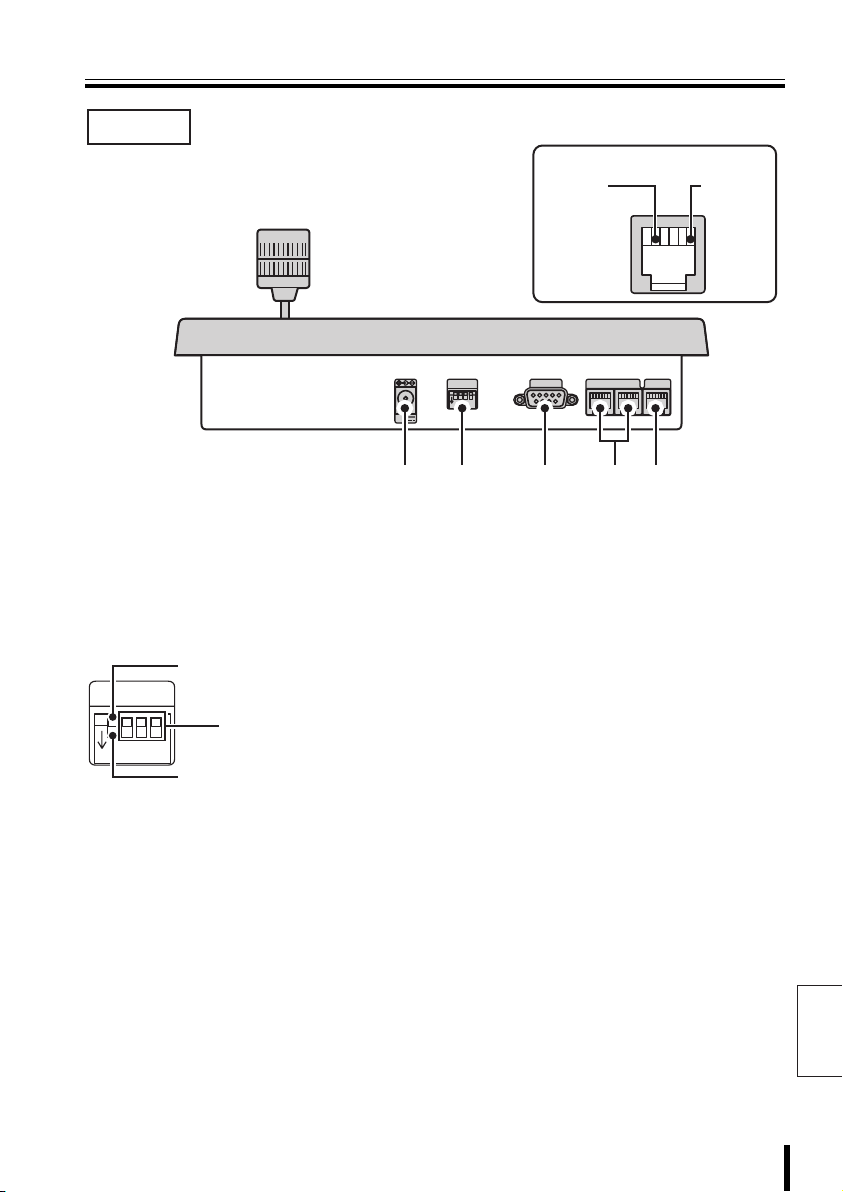
Part Names
Rear
RS485 (RJ-11) Terminal
B Signal
COMSW
TELEMETRY
1
234
ON
12V
AB
1 2 3 4 5
A Signal
VIDEO
1 Power terminal
Connect the DC terminal on the AC adapter
provided.
2 Dipswitch (SW)
Used for PC settings, communication settings,
or terminate settings on this unit.
When using as a system
controller, set to this position.
(OFF)
234
Use for ON/OFF settings for
each terminate setup.
When using the provided PC
software. (ON: P60)
ON
SW
1
3 PC connection terminal
(COM: RS-232C)
Use for connecting to a PC.
Install software on the provided CD-ROM to a
connected PC to add other languages, etc.
Use the language selection in system setup to
select an added language. This changes the
menu display language.
4 Camera communication
terminal (TELEMETRY A/B)
Connect a provided or separately purchased
modular cable to this terminal.
• Terminal A: Connect a camera.
• Terminal B: Connect a camera.
5 Video communication terminal
(VIDEO)
Connect video equipment (multiplexer, hard
disk digital recorder, etc.)
When connecting this unit with video
equipment, always use the provided modular
cable and communication conversion
connector.
English
Preparation 10
Page 12
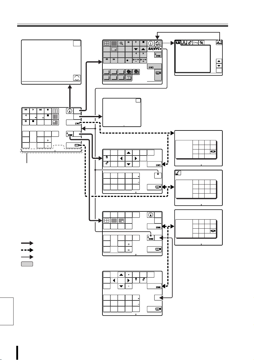
Menu Display
CAM 1 DVR 1
GENERAL INFORMATION
UNDER SELECTION
TELEMETRY
VIDEO
ENGLISH
LANGUAGE
00000
00100
00001
ESC
CAM 1 MUX 2
00000
00100
00001
00000
00100
00001
CAM 1 DVR 1
CAM 1 DVR 1
CAM 1 DVR 1
CAM 1 DVR 1
Esc to exit
CAM 1 MUX 1
Esc to exit
CAM 1 DVR 1
Esc to exit
b System Information
GENERAL INFORMATION
UNDER SELECTION
Present camera.......: 00001
Camera address.......: 00001
Monitor/Unit.........: 00001
A/B/V line...........: V
TELEMETRY
Connector.........(A): Video
Protocol..........(A): SANYO SSP
Baudrate..........(A): -----
Connector.........(B): Telemetry
Protocol..........(B): ----------
Baudrate..........(B): -----
VIDEO
Type.................: DVR/MUX
Protocol.............: SANYO DVR/MU
Baudrate.............: 19200
Keyboard address.....: 00001
Firmware version.....:
b Main Menu
ALARM PLAY
R PLAY
STILL
SEQ
ON
PAN
ON
TOUR
ON
CAM 1 DVR 1
CAM 1 DVR 1
PLAY
SPEED
PLAY STOP
SEQ/
PAN/
TOUR
OFF
PLAY
SPEED
CLOCK
ADJUST
ONE PUSH
AF
FOCUS
FAR
FOCUS
NEAR
RECALARM
REC STOP
TIMER
ON/OFF
IRIS
CENTER
IRIS
IRIS
Message display
: Nested menus
: Password-protected
: Main Menu
: Operation buttons
unavailable
English
GO TO
PRESET
esc
SERVICE
i
SYSTEM
SETUP
MAP
ENTER
DVR
ADDRESS ?
TO SUB
MUX
SCREEN
ADDRESS ?
b System Setup
PLAY
STILL
MONITOR
MENU
2
SEARCH
TIMER
SEQUENCE
REC STOP REC
ALARM ALARM
AUTOPAN AUTOFLIP
AUX
PROG SCAN
PATRO L
Go to user-created map
test ...
test ...
CAM 1 MUX 2
b Video/Camera Operation
Sub-screen
SEARCH
MAIN
MON2
FR/FI
MONITOR
SEQUENCE
LOCK
AUDIO
COPY
UNLOCK
BLC
AUX
AWB
ON
ON
SET
AWB
BLC
AUX
RESET
OFF
OFF
ZOOM
ZOOM
PRESET
PRESET
PRESET
MEMORY
OFF
ON
CAM 1 DVR 1
b Video/Camera Operation
Screen
SPOT
SPOT
SPOT
1
2
MON.
CAM 1 DVR 1
3
MON.
MON.
ZOOM
SEQUENCE
STILL
ONE PUSH
SEQ
SEQ/
AF
ON
PAN/
TOUR
PAN
FOCUS
OFF
ON
FAR
FOCUS
TOUR
NEAR
ON
EXIT/OSD
COPY
MENU
ELS
ON
ELS
OFF
SPOT
MON.
LIVE
VCR
IRIS
CENTER
IRIS
IRIS
STOP
SYSTEM
MUX
ENTERCLEAR
DVR
1
1
ESC
MENU
ZOOM
CHANNEL
RESET
TO
10 KEY
EXIT/OSD
L-L
PHASE
L-L
PHASE
MENUCODE
MAIN
MONITOR
4
GO TO
PRESET
DVR
ADDRESS ?
TO MAIN
SCREEN
ADDRESS ?
SYSTEM
SETUP
MAP
ENTER
MUX
ADDRESS ?
TO SUB
DVR
SCREEN
ADDRESS ?
b Video/Camera Operation
Sub-screen
CLOCK
MENU
MENU
NEXT
BACK
BLC
AUX
AWB
SET
AWB
RESET
PRESET
MEMORY
CAM 1 DVR 1
AUX
OFF
ZOOM
PRESET
ELS
ON
ON
ON
ELS
BLC
OFF
OFF
ZOOM
CODE
PRESET
OFF
ON
RESET
LOCK UNLOCK
L-L
PHASE
L-L
PHASE
MENU
POWER
ADJUST
ON/OFF
MUX
ADDRESS ?
TO MAIN
SCREEN
ADDRESS ?
LANGUAGE
1-ITALIANO
> 2-ENGLISH
3-FRANÇAIS
4-DEUTSCH
5-********
6-********
7-********
8-********
9-********
10-********
11-********
12-********
ENABLED:
ENGLISH
(System setup nested
screen)
b Address Input
Screen
Datum: 00000
00000
Accept.values
Max 00100
Min 00001
Digit
Dvr nr.
CAM 1 DVR 1
Esc to exit
1
Datum: 00000
00000
Accept.values
Max 00100
Min 00001
Digit
Camera nr.
CAM 1 DVR 1
Esc to exit
Datum: 00000
00000
Accept.values
Max 00100
Min 00001
Digit
Mux nr.
CAM 1 MUX 1
Esc to exit
123
456
78
.
0
?
123
456
78
.
0
123
456
78
.
0
9
enter
9
enter
9
enter
esc
esc
esc
ent
del
del
del
11 Preparation
Page 13
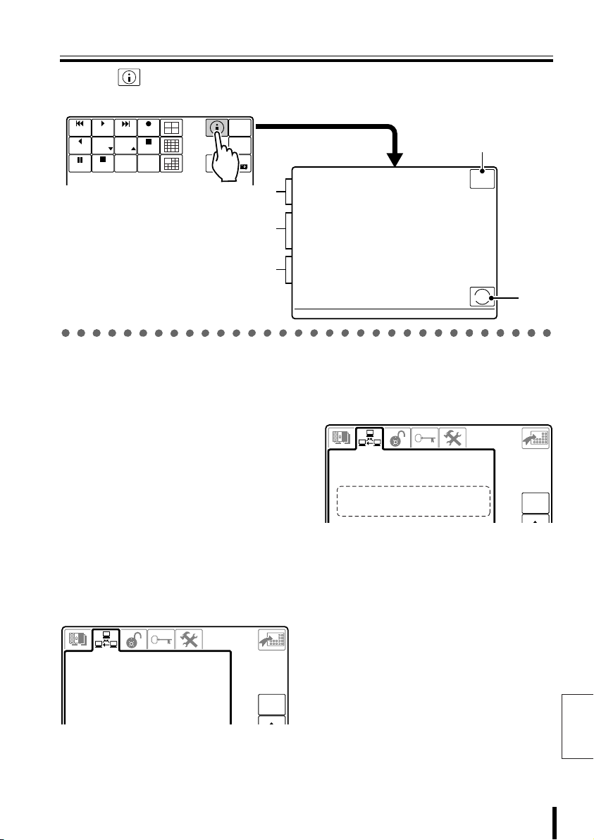
System Information
2-TELEMETRY
1-VIDEO
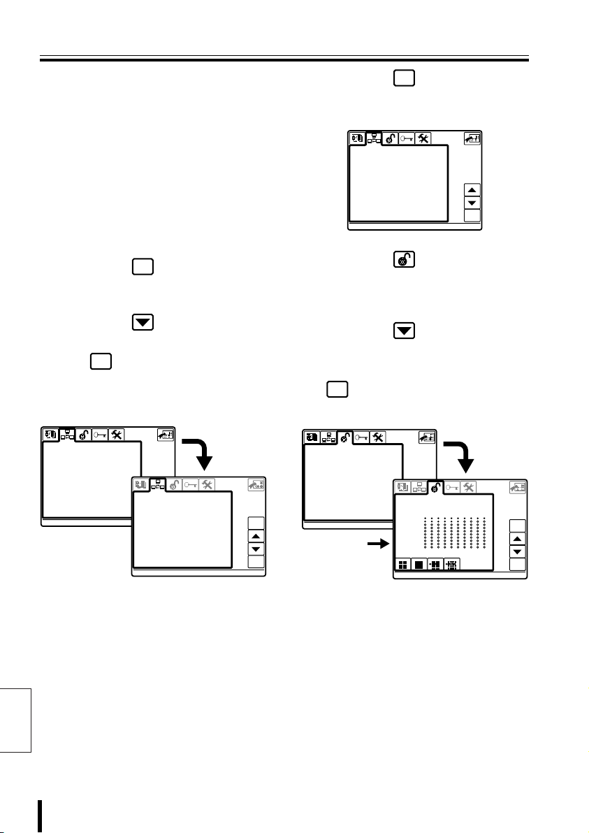
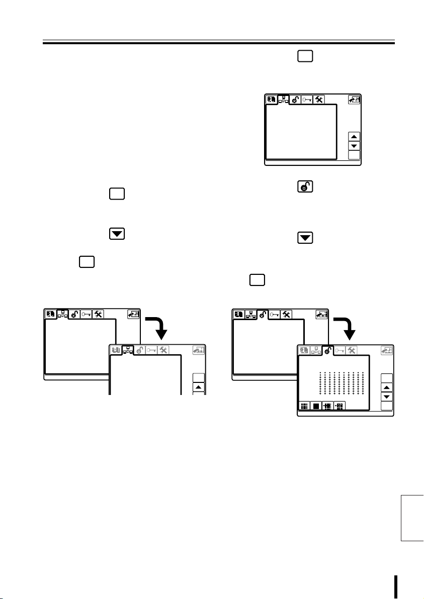
Press the button to display the current initial settings information for this unit. These
settings change when communication line settings have been changed in System Setup.
ADDRESS ?
SYSTEM
SETUP
MAP
ENTER
DVR
ALARM
R PLAY
STILL
PLAY
PLAY
SPEED
PLAY STOP
PLAY
SPEED
CLOCK
ADJUST
RECALARM
REC STOP
TIMER
ON/OFF
1
2
3
1 Status of selected equipment
(UNDER SELECTION)
• Present camera (00001)
Currently selected camera channel
• Camera address (00001)
Currently selected camera address
• Monitor/Unit (00001)
Currently selected video equipment (DVR/
MUX) address
• A/B/V line (V)
Currently selected line (displayed line sends
command to camera)
2 Communication status for
video equipment or camera
(TELEMETRY)
Displays the communication settings set in
“2–TELEMETRY”. (P45)
4
GENERAL INFORMATION
UNDER SELECTION
Present camera.......: 00001
Camera address.......: 00001
Monitor/Unit.........: 00001
A/B/V line...........: V
TELEMETRY
Connector.........(A): Video
Protocol..........(A): SANYO SSP
Baudrate..........(A): -----
Connector.........(B): Telemetry
Protocol..........(B): ----------
Baudrate..........(B): -----
VIDEO
Type.................: DVR/MUX
Protocol.............: SANYO DVR/MU
Baudrate.............: 19200
Keyboard address.....: 00001
Firmware version.....:
esc
SERVICE
i
3 Communication status for
video equipment (VIDEO)
Displays the communication settings set in
“1–VIDEO” and the address for this unit. (P44)
COMMUNICATIONS
1-VIDEO
>Type : DVR/MUX
Protocol : SANYO DVR/MU
Baudrate : 19200
Keyboard Add: 00001
• Address for this unit (Keyboard Add): 00001
(P44)
4 Returns to Main Menu.
5 Displays system installer
information.
5
esc
COMMUNICATIONS
2-TELEMETRY
>A-Connector Video
A-Protocol SANYO SSP
A-Baudrate ---- B-Connector Telemetry
B-Protocol --------- B-Baudrate -----
esc
English
Preparation 12
Page 14
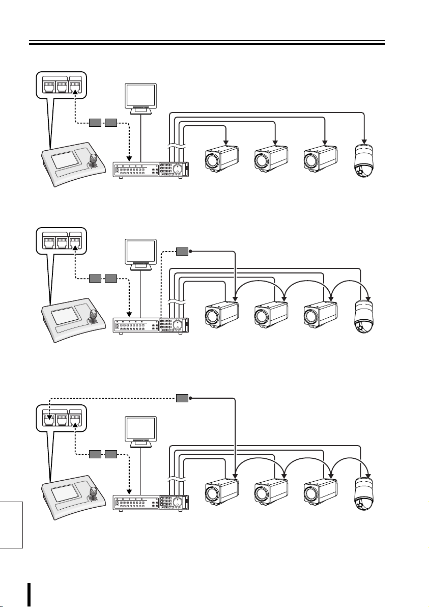
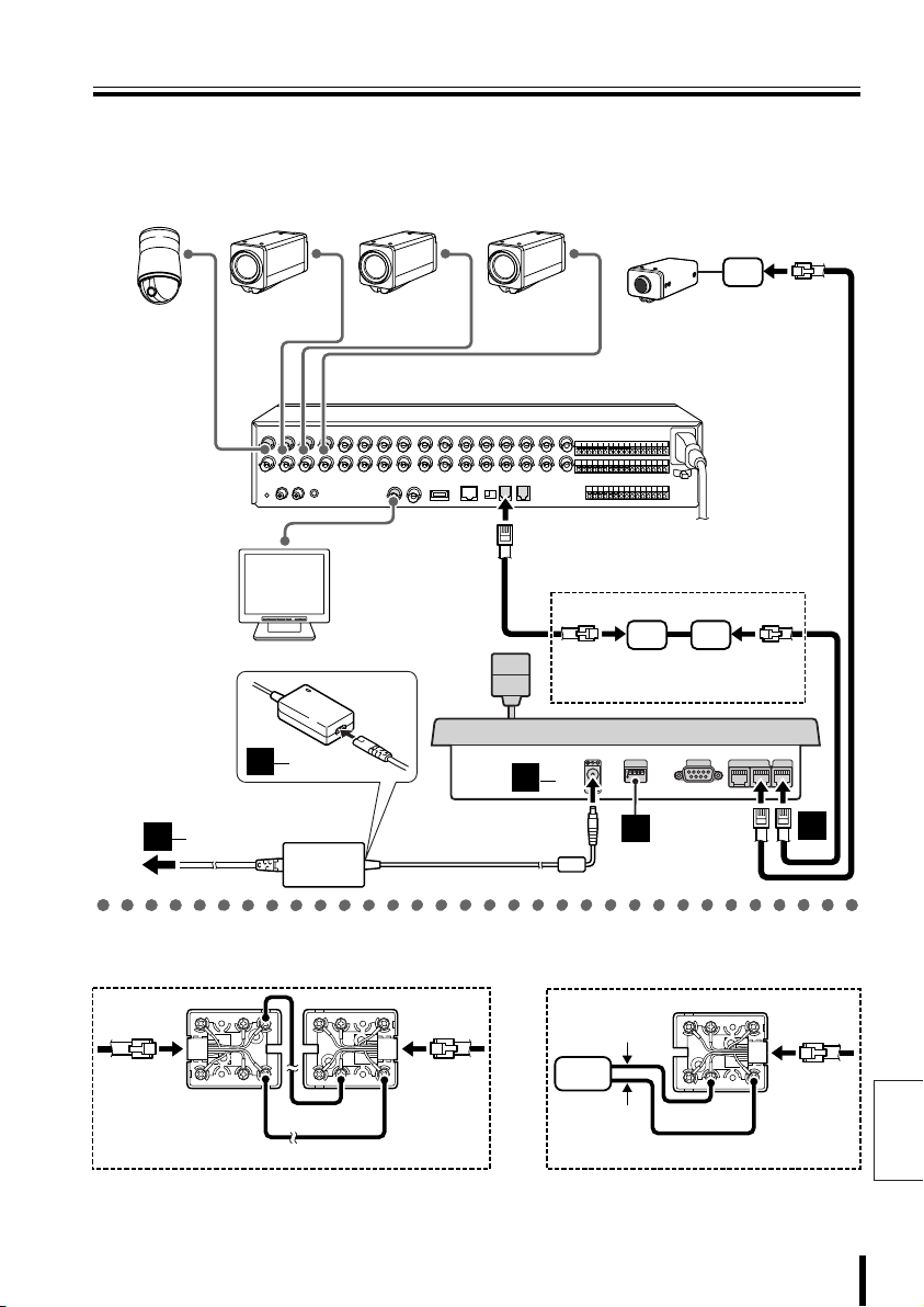
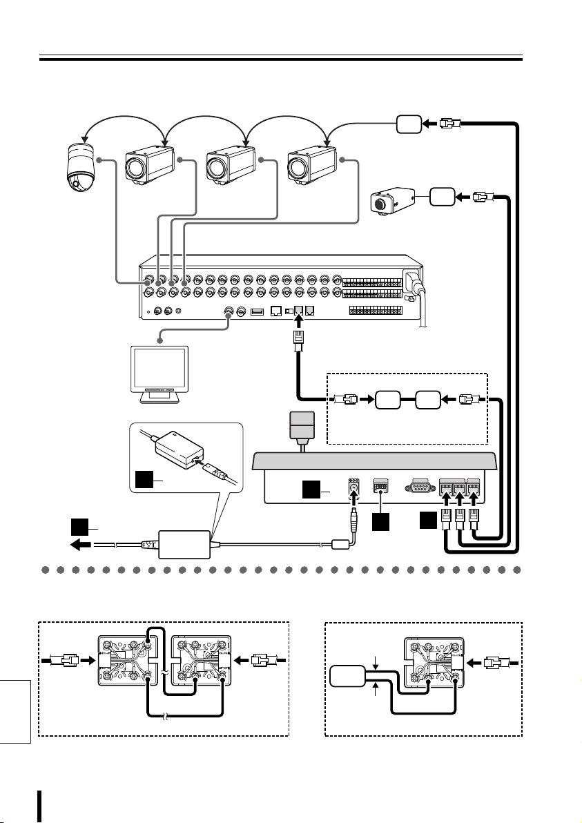
Sample System Connection
A When connected to video communication terminal (VIDEO) P15
TELEMETRY
VIDEOAB
Monitor
Modular
cable
Conversion
connector
RS485 A Terminal
CARDCARD
MENU
RESET
EJECT
Zoom
camera
Coaxial cable
Zoom
camera
Zoom
camera
Dome
camera
B When connected to video communication terminal (VIDEO) P18
TELEMETRY
VIDEOAB
Modular
cable
Conversion
connector
Monitor
B
RS485 A Terminal
A/B
Coaxial cable
CARDCARD
MENU
RESET
EJECT
Zoom
camera
Zoom
camera
Zoom
camera
Dome
camera
C When connected to video communication terminal (VIDEO)
and camera communication terminal (TELEMETRY A) P21
TELEMETRY
English
13 Preparation
VIDEOAB
Modular
cable
Conversion
connector
Monitor
RS485 A Terminal
A/B
Coaxial cable
CARDCARD
MENU
RESET
EJECT
Zoom
camera
Zoom
camera
Zoom
camera
Dome
camera
Page 15
Sample System Connection
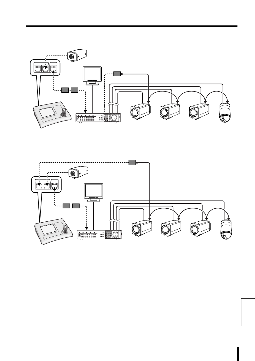
D When connected to video communication terminal (VIDEO)
and camera communication terminal (TELEMETRY B) P24
(Competitor camera)
TELEMETRY
VIDEOAB
Monitor
Modular
cable
Conversion
connector
RS485 A Terminal
A/B
B
CARDCARD
MENU
RESET
EJECT
Zoom
camera
Coaxial cable
Zoom
camera
Zoom
camera
E When connected to video communication terminal (VIDEO)
and camera communication terminals (TELEMETRY A/B) P27
TELEMETRY
VIDEOAB
Modular
cable
Conversion
connector
(Competitor
camera)
Monitor
RS485 A Terminal
A/B
Coaxial cable
CARDCARD
MENU
RESET
EJECT
Zoom
camera
Zoom
camera
Zoom
camera
Dome
camera
Dome
camera
Preparation 14
English
Page 16
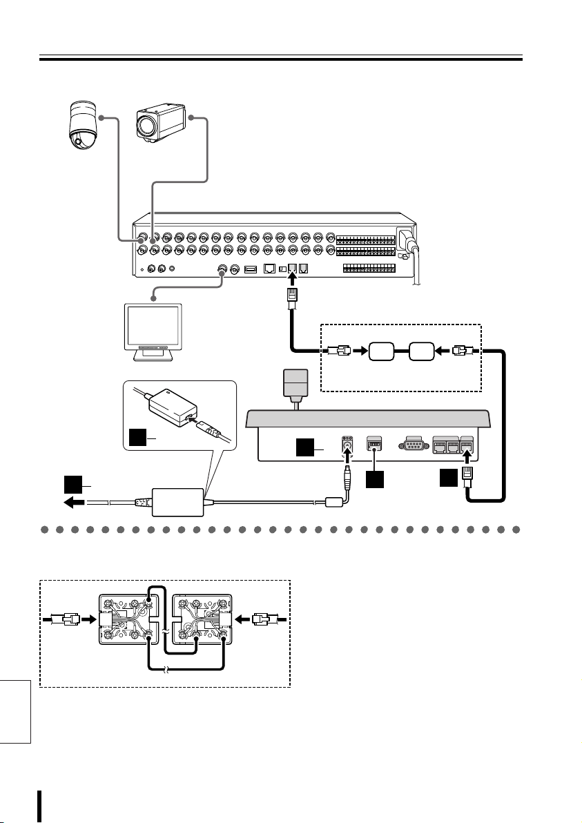
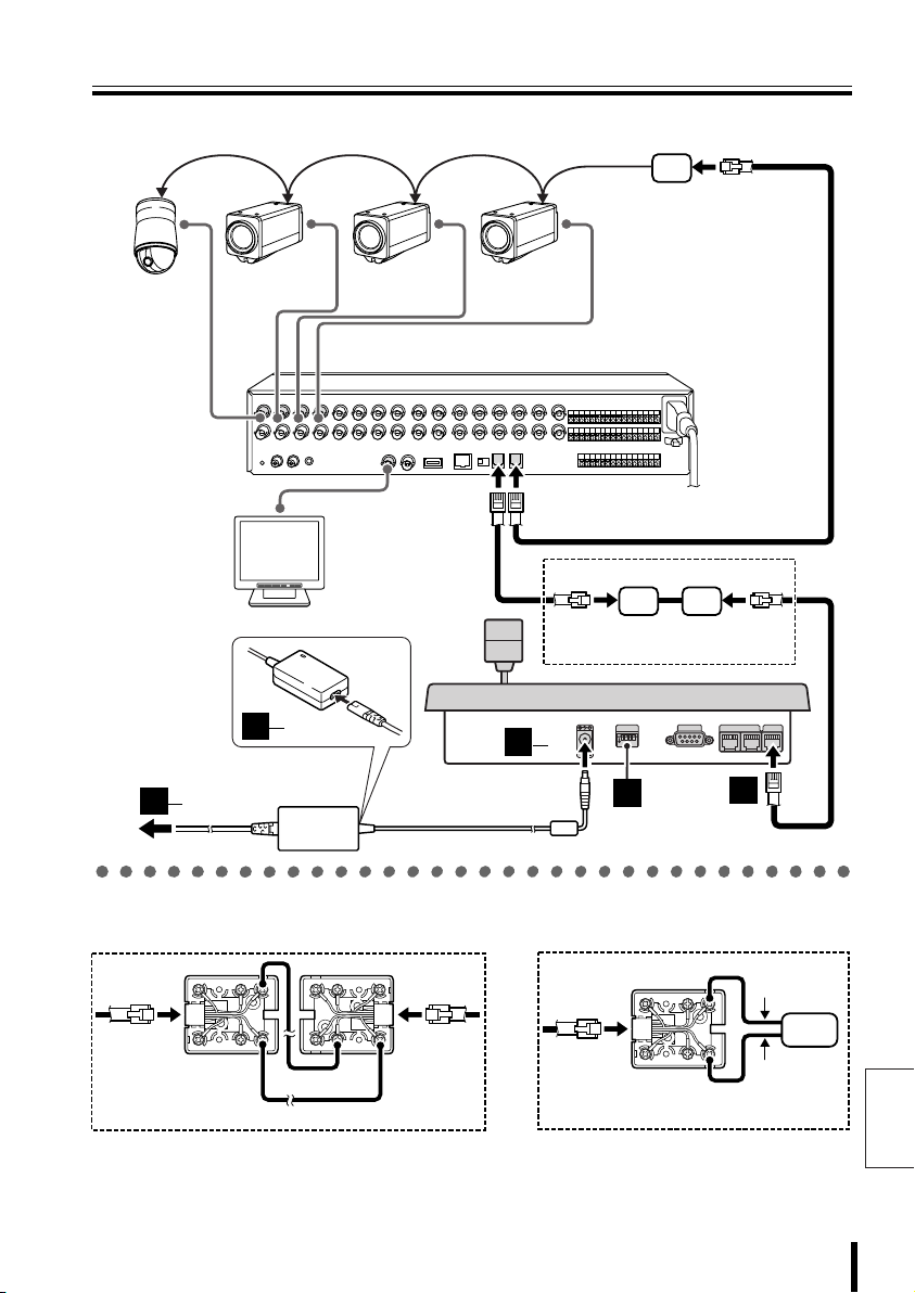
Connection and Communication Setup 1
A When connected to video communication terminal (VIDEO)
Dome camera
(sold separately)
3
3
Zoom camera
(sold separately)
with multiplexer function (sold separately)
2
1
IN
Monitor
(sold separately)
3
2
AC adapter
(provided)
Hard disk digital recorder
MONITOR OUT
MAIN
A
RS-485
B
3
(A) (B)
Provided communication
conversion connector
1
234
1
ON
12V
2
COMSW
TELEMETRY
VIDEO
AB
1
bbbb Connecting communication conversion connectors
English
Green
G
R
B
R
S
L
Y
L
WH
B
L
O
R
B
K
R
D
Red
(A) (B)
K
R
D
L
G
R
Yellow
O
R
B
B
L
WH
Y
S
L
B
R
White
15 Preparation
Page 17
Connection and Communication Setup 1
CAM 1 DVR 1
ENGLISH
LANGUAGE
COMMUNICATIONS
1-VIDEO
COMMUNICATIONS
bbbb Making Connections
Connect this unit to equipment
1111
for communication and
operation.
Before connecting, make sure all
equipment is turned off.
Terminate Setup.
2222
SW
1
ON
Connect this unit to its power
3333
source.
1 Connect the DC terminal on the AC
adapter to the power terminal.
2 Plug power plug into AC adapter.
3 Plug power plug into AC power supply.
This unit is turned on, and the main menu
appears on the menu display.
SW1: OFF (Fixed)
SW2: OFF (For Camera A)
SW3: OFF (For Camera B)
234
SW4: ON (For Video)
PLAY
VSP-9000
ALARM
R PLAY
STILL
SEQ
ON
PAN
ON
TOUR
ON
CAM 1 DVR 1
PLAY
SPEED
PLAY STOP
SEQ/
PAN/
TOUR
OFF
PLAY
SPEED
CLOCK
ADJUST
ONE PUSH
AF
FOCUS
FAR
FOCUS
NEAR
REC STOP
TIMER
ON/OFF
CENTER
RECALARM
IRIS
GO TO
PRESET
IRIS
IRIS
• This unit has no power switch.
Turn power ON or OFF by
plugging or unplugging the DC
plug from the AC adapter.
• When a startup password is set,
the password entry screen
appears. (P51)
ADDRESS ?
MUX
ADDRESS ?
SYSTEM
SETUP
MAP
ENTER
TO SUB
SCREEN
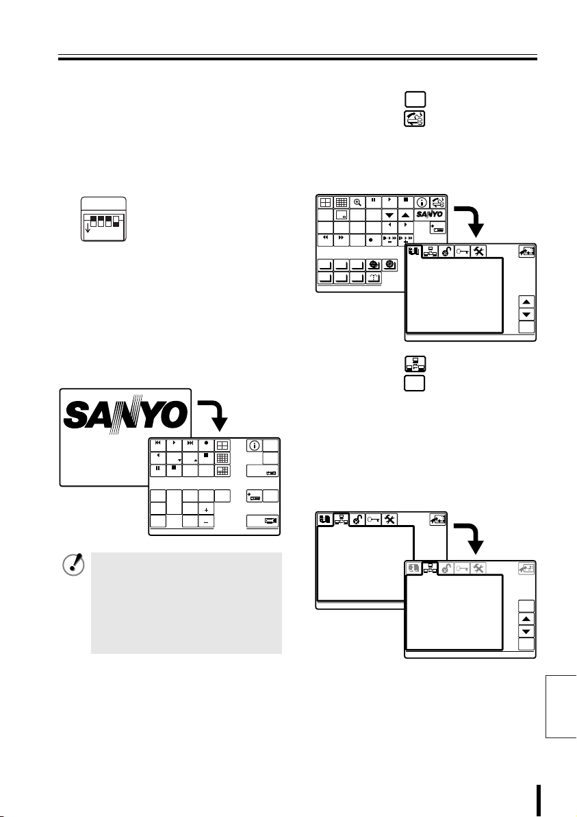
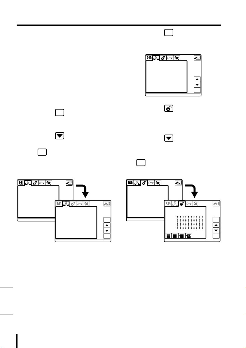
bbbb Communication Setup
SYSTEM
Press the button, then
1
SETUP
press the button.
The language selection screen
(LANGUAGE) is displayed. Select a
language if operating in a language other
than English. (P42)
PLAY
STILL
MONITOR
MENU
2
SEARCH
TIMER
SEQUENCE
REC STOP REC
ALARM ALARM
AUTOPAN AUTOFLIP
AUX
PROG SCAN
PATRO L
Press the button, then
2
press the button.
Displays the “1–VIDEO” screen for
communications setup
(COMMUNICATIONS).
When communications operations are
DVR
performed only through the video
communication terminal (VIDEO) on the
rear of this unit, confirm that the screen is
as shown in Figure 1.
COMMUNICATIONS
>1-VIDEO
2-TELEMETRY
3-SERIAL TESTS
EXIT/OSD
COPY
STOP
SYSTEM
MUX
ENTERCLEAR
DVR
1
LANGUAGE
1-ITALIANO
1
> 2-ENGLISH
3-FRANÇAIS
4-DEUTSCH
5-********
6-********
7-********
8-********
9-********
10-********
11-********
12-********
ENABLED:
ENGLISH
ent
COMMUNICATIONS
1-VIDEO
ent
>Type : DVR/MUX
Protocol : SANYO DVR/MU
Baudrate : 19200
Keyboard Add: 00001
ent
esc
ent
(Figure 1)
Note: To change the address of this unit
(Keyboard Add), see P44.
English
Preparation 16
Page 18
Connection and Communication Setup 1 (continued)
COMMUNICATIONS
2-TELEMETRY
COMMUNICATIONS
COMMUNICATIONS
ACCEPTED VALUES
2-MONITOR/LOCAL DVR-MUX
ACCEPTED VALUES
Check Setup:
• Type:
• Protocol:
• Baudrate:
3
4
Check Setup:
• A-Connector:
• A-Protocol:
English
• A-Baudrate:
To operate a hard disk digital recorder with
a multiplexer function, this should display
“DVR/MUX”.
When “DVR/MUX” is selected for “Type”,
“SANYO DVR/MU” is automatically
displayed.
“19200” is automatically displayed.
Match the settings of the connected
equipment.
Press the button.
esc
Returns to Communication Setup
selection screen.
Press the button, select
“2–TELEMETRY”, then press
ent
the button.
The “2–TELEMETRY” screen is
displayed. Check that the settings are as
shown below.
COMMUNICATIONS
1-VIDEO
>2-TELEMETRY
3-SERIAL TESTS
To operate a camera via video equipment,
this should display “Video”.
When “Video” is selected for “A-Connector”,
“SANYO SSP” is automatically displayed.
Because 1–VIDEO is then set to “Baudrate
(19200)”, “– – – – –” is displayed by default.
COMMUNICATIONS
2-TELEMETRY
>A-Connector Video
A-Protocol SANYO SSP
A-Baudrate ---- B-Connector Telemetry
B-Protocol --------- B-Baudrate -----
ent
esc
ent
Press the button.
5
esc
Returns to Communication Setup
(COMMUNICATIONS).
COMMUNICATIONS
>1-VIDEO
2-TELEMETRY
3-SERIAL TESTS
Press the button.
6
ent
Displays Control Setup (ACCEPTED
VALUES) screen.
For “1–CAMERAS” setup, see P47.
Press the button, select
7
“2–MONITOR/LOCAL
DVR-MUX”, then press the
ent
button.
Set the connected DVR-MUX.
ACCEPTED VALUES
1-CAMERAS
>2-MONITOR/LOCAL DVR-MUX
3-FUNCTIONS
This completes the setup.
8
ACCEPTED VALUES
2-MONITOR/LOCAL DVR-MUX
ent
> 1
11
21
31
41
51
61
71
81
91
(Figure 2)
Proceed to operating the hard
disk digital recorder (P32) or
the camera (P38).
esc
ent
17 Preparation
Page 19
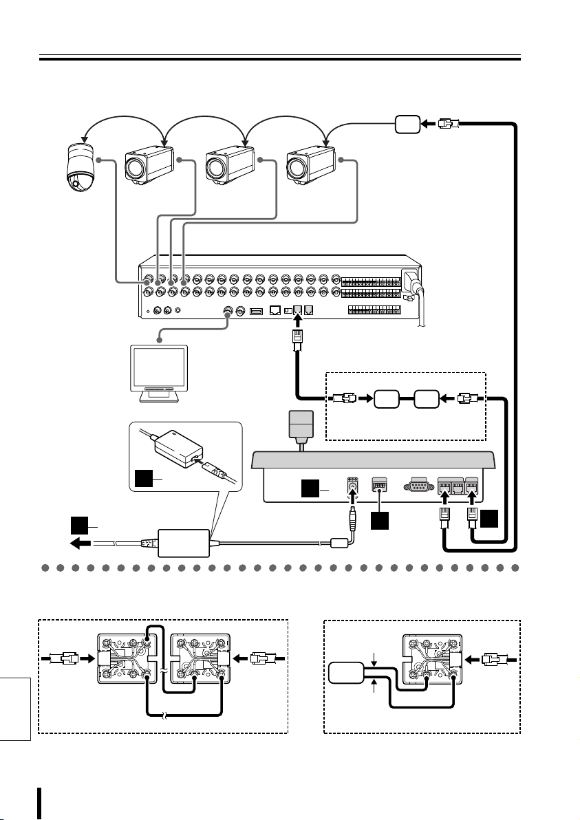
Connection and Communication Setup 2
B When connected to video communication terminal (VIDEO)
Provided communication
conversion connectors
(Figure 2)
Dome camera
(sold separately)
3
3
Zoom camera
(sold separately)
2
1
IN
3
2
AC adapter
(provided)
Zoom camera
(sold separately)
Zoom camera
(sold separately)
Hard disk digital recorder
with multiplexer function (sold separately)
MONITOR OUT
MAIN
A
RS-485
B
Monitor
(sold separately)
Provided communication
conversion connectors (Figure 1)
3
1
12V
(A) (B)
COMSW
1
234
ON
2
TELEMETRY
VIDEO
AB
1
b Connecting communication
conversion connectors (Figure 1)
Green
G
R
B
R
S
L
Y
L
WH
B
L
O
R
B
K
R
D
Red
(A) (B)
K
R
D
L
G
R
Yellow
O
R
B
B
L
WH
Y
S
L
B
R
White
b
Connecting communication
conversion connectors (Figure 2)
Green
B
R
S
L
Y
L
WH
B
L
O
R
B
K
Red
Preparation 18
B
G
R
Camera
R
D
A
English
Page 20

Connection and Communication Setup 2 (continued)
CAM 1 DVR 1
ENGLISH
LANGUAGE
COMMUNICATIONS
1-VIDEO
COMMUNICATIONS
bbbb Making Connections
Connect this unit to equipment
1111
for communication and
operation.
Before connecting, make sure all
equipment is turned off.
Terminate Setup.
2222
SW
1
ON
Connect this unit to its power
3333
source.
1 Connect the DC terminal on the AC
adapter to the power terminal.
2 Plug power plug into AC adapter.
3 Plug power plug into AC power supply.
This unit is turned on, and the main menu
appears on the menu display.
SW1: OFF (Fixed)
SW2: OFF (For Camera A)
SW3: OFF (For Camera B)
234
SW4: ON (For Video)
PLAY
VSP-9000
ALARM
R PLAY
STILL
SEQ
ON
PAN
ON
TOUR
ON
CAM 1 DVR 1
PLAY
SPEED
PLAY STOP
SEQ/
PAN/
TOUR
OFF
PLAY
SPEED
CLOCK
ADJUST
ONE PUSH
AF
FOCUS
FAR
FOCUS
NEAR
REC STOP
TIMER
ON/OFF
CENTER
RECALARM
IRIS
GO TO
PRESET
IRIS
IRIS
• This unit has no power switch.
Turn power ON or OFF by
plugging or unplugging the DC
plug from the AC adapter.
• When a startup password is set,
the password entry screen
appears. (P51)
ADDRESS ?
MUX
ADDRESS ?
SYSTEM
SETUP
ENTER
TO SUB
SCREEN
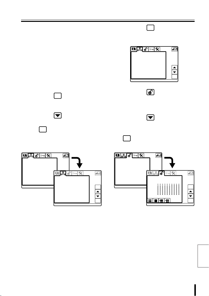
bbbb Communication Setup
SYSTEM
Press the button, then
1
SETUP
press the button.
The language selection screen
(LANGUAGE) is displayed. Select a
language if operating in a language other
than English. (P42)
PLAY
STILL
MONITOR
MENU
2
SEARCH
TIMER
SEQUENCE
REC STOP REC
ALARM ALARM
AUTOPAN AUTOFLIP
AUX
PROG SCAN
PATRO L
Press the button, then
2
press the button.
Displays the “1–VIDEO” screen for
communications setup
(COMMUNICATIONS).
MAP
DVR
When communications operations are
performed only through the video
communication terminal (VIDEO) on the
rear of this unit, confirm that the screen is
as shown in Figure 1.
COMMUNICATIONS
>1-VIDEO
2-TELEMETRY
3-SERIAL TESTS
EXIT/OSD
COPY
STOP
SYSTEM
MUX
ENTERCLEAR
DVR
1
LANGUAGE
1-ITALIANO
1
> 2-ENGLISH
3-FRANÇAIS
4-DEUTSCH
5-********
6-********
7-********
8-********
9-********
10-********
11-********
12-********
ENABLED:
ENGLISH
ent
COMMUNICATIONS
1-VIDEO
ent
>Type : DVR/MUX
Protocol : SANYO DVR/MU
Baudrate : 19200
Keyboard Add: 00001
ent
esc
ent
English
19 Preparation
(Figure 1)
Note: To change the address of this unit
(Keyboard Add), see P44.
Page 21
Connection and Communication Setup 2
COMMUNICATIONS
2-TELEMETRY
COMMUNICATIONS
COMMUNICATIONS
ACCEPTED VALUES
2-MONITOR/LOCAL DVR-MUX
ACCEPTED VALUES
Check Setup:
• Type:
To operate a hard disk digital recorder with
a multiplexer function, this should display
“DVR/MUX”.
• Protocol:
When “DVR/MUX” is selected for “Type”,
“SANYO DVR/MU” is automatically
displayed.
• Baudrate:
“19200” is automatically displayed.
Match the settings of the connected
equipment.
Press the button.
3
esc
Returns to Communication Setup
selection screen.
Press the button, select
4
“2–TELEMETRY”, then press
ent
the button.
The “2–TELEMETRY” screen is
displayed. Check that the settings are as
shown below.
COMMUNICATIONS
1-VIDEO
>2-TELEMETRY
3-SERIAL TESTS
Check Setup:
• A-Connector:
To operate a camera via video equipment,
this should display “Video”.
• A-Protocol:
When “Video” is selected for “A-Connector”,
“SANYO SSP” is automatically displayed.
• A-Baudrate:
Because 1–VIDEO is then set to “Baudrate
(19200)”, “– – – – –” is displayed by default.
COMMUNICATIONS
2-TELEMETRY
ent
>A-Connector Video
A-Protocol SANYO SSP
A-Baudrate ---- B-Connector Telemetry
B-Protocol --------- B-Baudrate -----
esc
ent
Press the button.
5
esc
Returns to Communication Setup
(COMMUNICATIONS).
COMMUNICATIONS
>1-VIDEO
2-TELEMETRY
3-SERIAL TESTS
Press the button.
6
ent
Displays Control Setup (ACCEPTED
VALUES) screen.
For “1–CAMERAS” setup, see P47.
Press the button, select
7
“2–MONITOR/LOCAL
DVR-MUX”, then press the
ent
button.
Set the connected DVR-MUX.
ACCEPTED VALUES
1-CAMERAS
>2-MONITOR/LOCAL DVR-MUX
3-FUNCTIONS
This completes the setup.
8
ACCEPTED VALUES
2-MONITOR/LOCAL DVR-MUX
> 1
11
21
31
41
51
61
71
81
91
(Figure 2)
Proceed to operating the hard
disk digital recorder (P32) or
the camera (P38).
esc
ent
English
Preparation 20
Page 22
Connection and Communication Setup 3
C When connected to video communication terminal (VIDEO) and camera
communication terminal (TELEMETRY A)
Provided communication
conversion connectors
(Figure 2)
Dome camera
(sold separately)
3
3
Zoom camera
(sold separately)
2
1
IN
3
2
AC adapter
(provided)
Zoom camera
(sold separately)
Zoom camera
(sold separately)
Hard disk digital recorder
with multiplexer function (sold separately)
MONITOR OUT
MAIN
B
RS-485
A
Monitor
(sold separately)
Provided communication
conversion connectors (Figure 1)
3
1
12V
(A) (B)
1
234
ON
2
COMSW
TELEMETRY
VIDEO
AB
1
b Connecting communication
conversion connectors (Figure 1)
English
Green
B
R
S
L
Y
WH
B
L
O
R
B
Red
(A) (B)
D
G
R
L
R
K
R
D
Yellow
21 Preparation
b
Connecting communication
conversion connectors (Figure 2)
O
R
B
K
R
G
B
L
B
WH
Y
L
S
L
B
R
White White
Camera
A
R
D
G
R
Yellow
O
R
B
K
B
L
WH
Y
L
S
L
B
R
Page 23

Connection and Communication Setup 3
CAM 1 DVR 1
ENGLISH
LANGUAGE
COMMUNICATIONS
1-VIDEO
COMMUNICATIONS
bbbb Making Connections
Connect this unit to equipment
1111
for communication and
operation.
Before connecting, make sure all
equipment is turned off.
Terminate Setup.
2222
SW
1
ON
Connect this unit to its power
3333
source.
1 Connect the DC terminal on the AC
adapter to the power terminal.
2 Plug power plug into AC adapter.
3 Plug power plug into AC power supply.
This unit is turned on, and the main menu
appears on the menu display.
SW1: OFF (Fixed)
SW2: ON (For Camera A)
SW3: OFF (For Camera B)
234
SW4: ON (For Video)
PLAY
VSP-9000
ALARM
R PLAY
STILL
SEQ
ON
PAN
ON
TOUR
ON
CAM 1 DVR 1
PLAY
SPEED
PLAY STOP
SEQ/
PAN/
TOUR
OFF
PLAY
SPEED
CLOCK
ADJUST
ONE PUSH
AF
FOCUS
FAR
FOCUS
NEAR
REC STOP
TIMER
ON/OFF
CENTER
RECALARM
IRIS
GO TO
PRESET
IRIS
IRIS
• This unit has no power switch.
Turn power ON or OFF by
plugging or unplugging the DC
plug from the AC adapter.
• When a startup password is set,
the password entry screen
appears. (P51)
ADDRESS ?
MUX
ADDRESS ?
SYSTEM
SETUP
MAP
ENTER
TO SUB
SCREEN
bbbb Communication Setup
SYSTEM
Press the button, then
1
SETUP
press the button.
The language selection screen
(LANGUAGE) is displayed. Select a
language if operating in a language other
than English. (P42)
PLAY
STOP
MONITOR
2
TIMER
ALARM ALARM
AUTOPAN AUTOFLIP
PATRO L
2
DVR
COMMUNICATIONS
>1-VIDEO
2-TELEMETRY
3-SERIAL TESTS
STILL
MENU
SEARCH
PROG SCAN
EXIT/OSD
SEQUENCE
REC STOP REC
AUX
COPY
ENTERCLEAR
LANGUAGE
1-ITALIANO
> 2-ENGLISH
3-FRANÇAIS
4-DEUTSCH
5-********
6-********
7-********
8-********
9-********
10-********
11-********
12-********
ENABLED:
ENGLISH
SYSTEM
MUX
DVR
1
1
ent
Press the button, then
press the button.
Displays the “1–VIDEO” screen for
communications setup
(COMMUNICATIONS).
When communications operations are
performed only through the video
communication terminal (VIDEO) on the
rear of this unit, confirm that the screen is
as shown in Figure 1.
ent
COMMUNICATIONS
1-VIDEO
ent
>Type : DVR/MUX
Protocol : SANYO DVR/MU
Baudrate : 19200
Keyboard Add: 00001
esc
ent
(Figure 1)
Note: To change the address of this unit
(Keyboard Add), see P44.
English
Preparation 22
Page 24
Connection and Communication Setup 3
COMMUNICATIONS
2-TELEMETRY
COMMUNICATIONS
COMMUNICATIONS
ACCEPTED VALUES
2-MONITOR/LOCAL DVR-MUX
ACCEPTED VALUES
Check Setup:
• Type:
To operate a hard disk digital recorder with
a multiplexer function, this should display
“DVR/MUX”.
• Protocol:
When “DVR/MUX” is selected for “Type”,
“SANYO DVR/MU” is automatically
displayed.
• Baudrate:
“19200” is automatically displayed. Match
the settings of the connected equipment
(DVR, etc.).
Press the button.
3
esc
Returns to Communication Setup
selection screen.
Press the button, select
4
“2–TELEMETRY”, then press
ent
the button.
The “2–TELEMETRY” screen is
displayed. Check that the settings are as
shown below.
COMMUNICATIONS
1-VIDEO
>2-TELEMETRY
3-SERIAL TESTS
COMMUNICATIONS
2-TELEMETRY
ent
>A-Connector Telemetry
A-Protocol SANYO SSP
A-Baudrate 19200
B-Connector Telemetry
B-Protocol --------- B-Baudrate -----
esc
ent
Press the button.
5
esc
Returns to Communication Setup
(COMMUNICATIONS).
COMMUNICATIONS
>1-VIDEO
2-TELEMETRY
3-SERIAL TESTS
Press the button.
6
Displays Control Setup (ACCEPTED
VALUES) screen.
For “1–CAMERAS” setup, see P47.
Press the button, select
7
“2–MONITOR/LOCAL
DVR-MUX”, then press the
ent
button.
Set the connected DVR-MUX.
ACCEPTED VALUES
1-CAMERAS
>2-MONITOR/LOCAL DVR-MUX
3-FUNCTIONS
(P47)
ACCEPTED VALUES
2-MONITOR/LOCAL DVR-MUX
> 1
11
21
31
41
51
61
71
81
91
ent
esc
ent
Check Setup:
• A-Connector:
• A-Protocol:
English
• A-Baudrate:
To operate a camera via video equipment,
this should display “Telemetry”.
Match the settings of the connected
camera.
Match the settings of the connected
camera.
23 Preparation
(Figure 2)
This completes the setup.
8
Proceed to operating the hard
disk digital recorder (P32) or
the camera (P38).
Page 25
Connection and Communication Setup 4
D When connected to video communication terminal (VIDEO) and camera
communication terminal (TELEMETRY B)
Provided communication
conversion connectors
(Figure 2)
Dome camera
(sold separately)
3
3
Zoom camera
(sold separately)
2
1
IN
3
2
AC adapter
(provided)
Zoom camera
(sold separately)
Zoom camera
(sold separately)
Hard disk digital recorder
with multiplexer function (sold separately)
MONITOR OUT
MAIN
A
RS-485
B
Monitor
(sold separately)
Provided communication
conversion connectors (Figure 1)
3
1
12V
(Competitor camera)
(A) (B)
COMSW
TELEMETRY
1
234
ON
AB
2
VIDEO
1
b Connecting communication
conversion connectors (Figure 1)
Green
G
R
B
R
S
L
Y
L
WH
B
L
O
R
B
K
R
D
Red
(A) (B)
K
R
D
L
G
R
Yellow
O
R
B
B
L
WH
Y
S
L
B
R
White White
b
Connecting communication
conversion connectors (Figure 2)
O
R
B
K
R
Camera
D
B
G
R
Yellow
A
Preparation 24
B
L
WH
Y
L
S
L
B
R
English
Page 26
Connection and Communication Setup 4 (continued)
CAM 1 DVR 1
ENGLISH
LANGUAGE
COMMUNICATIONS
1-VIDEO
COMMUNICATIONS
bbbb Making Connections
Connect this unit to equipment
1111
for communication and
operation.
Before connecting, make sure all
equipment is turned off.
Terminate Setup.
2222
SW
1
ON
Connect this unit to its power
3333
source.
1 Connect the DC terminal on the AC
adapter to the power terminal.
2 Plug power plug into AC adapter.
3 Plug power plug into AC power supply.
This unit is turned on, and the main menu
appears on the menu display.
SW1: OFF (Fixed)
SW2: OFF (For Camera A)
SW3: ON (For Camera B)
234
SW4: ON (For Video)
PLAY
VSP-9000
ALARM
R PLAY
STILL
SEQ
ON
PAN
ON
TOUR
ON
CAM 1 DVR 1
PLAY
SPEED
PLAY STOP
SEQ/
PAN/
TOUR
OFF
PLAY
SPEED
CLOCK
ADJUST
ONE PUSH
AF
FOCUS
FAR
FOCUS
NEAR
RECALARM
REC STOP
TIMER
ON/OFF
IRIS
CENTER
IRIS
IRIS
GO TO
PRESET
• This unit has no power switch.
Turn power ON or OFF by
plugging or unplugging the DC
plug from the AC adapter.
• When a startup password is set,
the password entry screen
appears. (P51)
ADDRESS ?
MUX
ADDRESS ?
SYSTEM
SETUP
ENTER
TO SUB
SCREEN
bbbb Communication Setup
SYSTEM
Press the button, then
1
SETUP
press the button.
The language selection screen
(LANGUAGE) is displayed. Select a
language if operating in a language other
than English. (P42)
PLAY
STILL
MONITOR
MENU
2
SEARCH
TIMER
SEQUENCE
REC STOP REC
ALARM ALARM
AUTOPAN AUTOFLIP
AUX
PROG SCAN
PATRO L
Press the button, then
2
press the button.
Displays the “1–VIDEO” screen for
communications setup
(COMMUNICATIONS).
MAP
DVR
When communications operations are
performed only through the video
communication terminal (VIDEO) on the
rear of this unit, confirm that the screen is
as shown in Figure 1.
COMMUNICATIONS
>1-VIDEO
2-TELEMETRY
3-SERIAL TESTS
EXIT/OSD
COPY
STOP
SYSTEM
MUX
ENTERCLEAR
DVR
1
LANGUAGE
1-ITALIANO
1
> 2-ENGLISH
3-FRANÇAIS
4-DEUTSCH
5-********
6-********
7-********
8-********
9-********
10-********
11-********
12-********
ENABLED:
ENGLISH
ent
COMMUNICATIONS
1-VIDEO
ent
>Type : DVR/MUX
Protocol : SANYO DVR/MU
Baudrate : 19200
Keyboard Add: 00001
ent
esc
ent
English
25 Preparation
(Figure 1)
Note: To change the address of this unit
(Keyboard Add), see P44.
Page 27
Connection and Communication Setup 4
COMMUNICATIONS
2-TELEMETRY
COMMUNICATIONS
COMMUNICATIONS
ACCEPTED VALUES
2-MONITOR/LOCAL DVR-MUX
ACCEPTED VALUES
Check Setup:
• Type:
To operate a hard disk digital recorder with
a multiplexer function, this should display
“DVR/MUX”.
• Protocol:
When “DVR/MUX” is selected for “Type”,
“SANYO DVR/MU” is automatically
displayed.
• Baudrate:
“19200” is automatically displayed.
Match the settings of the connected
equipment.
Press the button.
3
esc
Returns to Communication Setup
selection screen.
Press the button, select
4
“2–TELEMETRY”, then press
ent
the button.
The “2–TELEMETRY” screen is
displayed. Check that the settings are as
shown below.
COMMUNICATIONS
1-VIDEO
>2-TELEMETRY
3-SERIAL TESTS
Check Setup:
• A-Connector:
Select “Video”.
• A-Protocol:
Select “SANYO SSP”.
• A-Baudrate:
Because 1–VIDEO is then set to “Baudrate
(19200)”, “– – – – –” is displayed by default.
• B-Connector:
Select “Telemetry”.
• B-Protocol:
Match the settings of the connected
camera.
• B-Baudrate:
Match the settings of the connected
camera.
COMMUNICATIONS
2-TELEMETRY
ent
>A-Connector Video
A-Protocol SANYO SSP
A-Baudrate ---- B-Connector Telemetry
B-Protocol --------- B-Baudrate -----
esc
Press the button.
5
esc
Returns to Communication Setup
(COMMUNICATIONS).
COMMUNICATIONS
>1-VIDEO
2-TELEMETRY
3-SERIAL TESTS
Press the button.
6
ent
Displays Control Setup (ACCEPTED
VALUES) screen.
For “1–CAMERAS” setup, see P47.
Press the button, select
7
“2–MONITOR/LOCAL
DVR-MUX”, then press the
ent
button.
Set the connected DVR-MUX.
ACCEPTED VALUES
1-CAMERAS
>2-MONITOR/LOCAL DVR-MUX
3-FUNCTIONS
This completes the setup.
8
ACCEPTED VALUES
2-MONITOR/LOCAL DVR-MUX
> 1
11
21
31
41
51
61
71
81
91
(Figure 2)
Proceed to operating the hard
disk digital recorder (P32) or
the camera (P38).
Preparation 26
esc
ent
English
Page 28
Connection and Communication Setup 5
E When connected to video communication terminal (VIDEO) and camera
communication terminals (TELEMETRY A/B)
Provided communication
conversion connectors
(Figure 2)
Dome camera
(sold separately)
3
3
Zoom camera
(sold separately)
2
1
IN
3
2
AC adapter
(provided)
Zoom camera
(sold separately)
Zoom camera
(sold separately)
Hard disk digital recorder
with multiplexer function (sold separately)
MONITOR OUT
MAIN
B
RS-485
A
Monitor
(sold separately)
Provided communication
conversion connectors (Figure 1)
3
1
12V
(Competitor camera)
(A) (B)
COMSW
TELEMETRY
1
234
ON
2
AB
1
VIDEO
b Connecting communication
conversion connectors (Figure 1)
English
Green
B
R
S
L
Y
WH
B
L
O
R
B
Red
(A) (B)
D
G
R
L
R
K
R
D
Yellow
27 Preparation
b
Connecting communication
conversion connectors (Figure 2)
O
R
B
K
R
G
B
L
B
WH
Y
L
S
L
B
R
White White
Camera
A
R
D
G
R
Yellow
O
R
B
K
B
L
WH
Y
L
S
L
B
R
Page 29

Connection and Communication Setup 5
CAM 1 DVR 1
ENGLISH
LANGUAGE
COMMUNICATIONS
1-VIDEO
COMMUNICATIONS
bbbb Making Connections
Connect this unit to equipment
1111
for communication and
operation.
Before connecting, make sure all
equipment is turned off.
Terminate Setup.
2222
SW
1
ON
Connect this unit to its power
3333
source.
1 Connect the DC terminal on the AC
adapter to the power terminal.
2 Plug power plug into AC adapter.
3 Plug power plug into AC power supply.
This unit is turned on, and the main menu
appears on the menu display.
SW1: OFF (Fixed)
SW2: ON (For Camera A)
SW3: ON (For Camera B)
234
SW4: ON (For Video)
PLAY
VSP-9000
ALARM
R PLAY
STILL
SEQ
ON
PAN
ON
TOUR
ON
CAM 1 DVR 1
PLAY
SPEED
PLAY STOP
SEQ/
PAN/
TOUR
OFF
PLAY
SPEED
CLOCK
ADJUST
ONE PUSH
AF
FOCUS
FAR
FOCUS
NEAR
REC STOP
TIMER
ON/OFF
CENTER
RECALARM
IRIS
GO TO
PRESET
IRIS
IRIS
• This unit has no power switch.
Turn power ON or OFF by
plugging or unplugging the DC
plug from the AC adapter.
• When a startup password is set,
the password entry screen
appears. (P51)
ADDRESS ?
MUX
ADDRESS ?
SYSTEM
SETUP
MAP
ENTER
TO SUB
SCREEN
bbbb Communication Setup
SYSTEM
Press the button, then
1
SETUP
press the button.
The language selection screen
(LANGUAGE) is displayed. Select a
language if operating in a language other
than English. (P42)
PLAY
STOP
MONITOR
2
TIMER
ALARM ALARM
AUTOPAN AUTOFLIP
PATRO L
2
DVR
COMMUNICATIONS
>1-VIDEO
2-TELEMETRY
3-SERIAL TESTS
STILL
MENU
SEARCH
PROG SCAN
EXIT/OSD
SEQUENCE
REC STOP REC
AUX
COPY
ENTERCLEAR
LANGUAGE
1-ITALIANO
> 2-ENGLISH
3-FRANÇAIS
4-DEUTSCH
5-********
6-********
7-********
8-********
9-********
10-********
11-********
12-********
ENABLED:
ENGLISH
SYSTEM
MUX
DVR
1
1
ent
Press the button, then
press the button.
Displays the “1–VIDEO” screen for
communications setup
(COMMUNICATIONS).
When communications operations are
performed only through the video
communication terminal (VIDEO) on the
rear of this unit, confirm that the screen is
as shown in Figure 1.
ent
COMMUNICATIONS
1-VIDEO
ent
>Type : DVR/MUX
Protocol : SANYO DVR/MU
Baudrate : 19200
Keyboard Add: 00001
esc
ent
(Figure 1)
Note: To change the address of this unit
(Keyboard Add), see P44.
English
Preparation 28
Page 30

Connection and Communication Setup 5 (continued)
COMMUNICATIONS
2-TELEMETRY
COMMUNICATIONS
COMMUNICATIONS
ACCEPTED VALUES
2-MONITOR/LOCAL DVR-MUX
ACCEPTED VALUES
Check Setup:
• Type:
To operate a hard disk digital recorder with
a multiplexer function, this should display
“DVR/MUX”.
• Protocol:
When “DVR/MUX” is selected for “Type”,
“SANYO DVR/MU” is automatically
displayed.
• Baudrate:
“19200” is automatically displayed.
Match the settings of the connected
equipment.
Press the button.
3
esc
Returns to Communication Setup
selection screen.
Press the button, select
4
“2–TELEMETRY”, then press
ent
the button.
The “2–TELEMETRY” screen is
displayed. Check that the settings are as
shown below.
COMMUNICATIONS
1-VIDEO
>2-TELEMETRY
3-SERIAL TESTS
COMMUNICATIONS
2-TELEMETRY
>A-Connector Telemetry
A-Protocol SANYO SSP
A-Baudrate 19200
B-Connector Telemetry
B-Protocol PELCO
B-Baudrate 2400
Check Setup:
• A-Connector: Select “Telemetry”.
• A-Protocol:
Match the settings of the connected
camera.
• A-Baudrate:
Match the settings of the connected
camera.
• B-Connector: Select “Telemetry”.
• B-Protocol:
English
Match the settings of the connected
camera.
• B-Baudrate:
Match the settings of the connected
camera.
29 Preparation
ent
esc
Press the button.
5
esc
Returns to Communication Setup
(COMMUNICATIONS).
COMMUNICATIONS
>1-VIDEO
2-TELEMETRY
3-SERIAL TESTS
Press the button.
6
ent
Displays Control Setup (ACCEPTED
VALUES) screen.
For “1–CAMERAS” setup, see P47.
Press the button, select
7
“2–MONITOR/LOCAL
DVR-MUX”, then press the
ent
button.
Set the connected DVR-MUX.
ACCEPTED VALUES
1-CAMERAS
>2-MONITOR/LOCAL DVR-MUX
3-FUNCTIONS
This completes the setup.
8
ACCEPTED VALUES
2-MONITOR/LOCAL DVR-MUX
> 1
11
21
31
41
51
61
71
81
91
(Figure 2)
Proceed to operating the hard
disk digital recorder (P32) or
the camera (P38).
esc
ent
Page 31
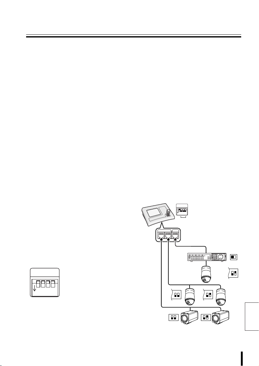
Communication Lines and Number of
Connected Units
This unit can operate multiple hard disk digital recorders with a multiplexer function
connected to the rear video terminal (VIDEO), or multiple dome or zoom cameras
connected to the camera terminals (TELEMETRY A/B).
Address and terminate settings are required after connecting the equipment. See your
operating manuals for proper settings of the connected equipment.
bbbb Number of Connected Units
• Maximum connections with this unit: 5 units (Address 0 to 4)
• Maximum connections of this unit with video terminal (hard disk digital recorders, multiplexers):
100 units (Address 1 to 100)
• Maximum connections of this unit with camera terminal (dome cameras, zoom cameras):
127 units (Address 1 to 127)
• Maximum number of connections within system: 256 units
Note: Connections between communication conversion connectors can be checked before using a
communication line.
See “Communications Setup”, “3–SERIAL TESTS” in System Setup. (P46)
bbbb Terminate settings
This unit is equipped with camera A/B communication terminals and a video communication
terminal. When performing communication operations, connecting multiple models to the same loop
from each communication terminal will cause the data to reflect at both ends, affecting other data
and preventing proper data transmission to each piece of equipment.
Terminate settings refer to enabling proper communication by turning ON the terminate switch
provided on equipment connected at both ends of multiple connected units, and turning OFF the
terminate switch on the connected units in between.
Dipswitches (SW) 2 to 4 on the rear panel are
the terminate setting switches.
• SW1: For selecting PC software operation
or normal operation
• SW2: For terminate setting on camera
communication terminal A
• SW3: For terminate setting on camera
communication terminal B
• SW4: For terminate setting for video
communication terminal
SW
1
234
ON
SW
1
ON
TELEMETRY
VIDEOAB
OFF ON
(Sample Settings)
234
ON
Preparation 30
CARDCARD
MENU
RESET
EJECT
OFF
ON
ONOFF
English
Page 32

Communication Lines and Number of Connected Units (Continued)
SW
O
R
B
K
R
D
B
L
WH
Y
L
S
L
B
R
G
R
O
R
B
K
R
D
B
L
WH
Y
L
S
L
B
R
G
R
O
R
B
K
R
D
B
L
WH
Y
L
S
L
B
R
G
R
O
R
B
K
R
D
B
L
WH
Y
L
S
L
B
R
G
R
O
R
B
K
R
D
B
L
WH
Y
L
S
L
B
R
G
R
1234567ON1234567ON1234567
ON
1
1
234
ON
COMSW
TELEMETRY
VIDEO
AB
1
234
ON
12V
SW
2
1
234
ON
COMSW
TELEMETRY
VIDEO
AB
1
234
ON
12V
SW
3
1
234
ON
COMSW
TELEMETRY
VIDEO
AB
1
234
ON
12V
SW
4
1
234
ON
COMSW
TELEMETRY
VIDEO
AB
1
234
ON
12V
SW
5
1
234
ON
COMSW
TELEMETRY
VIDEO
AB
1
234
ON
12V
G
R
B
R
S
L
Y
L
WH
B
L
O
R
B
K
R
D
G
R
B
R
S
L
Y
L
WH
B
L
O
R
B
K
R
D
G
R
B
R
S
L
Y
L
WH
B
L
O
R
B
K
R
D
G
R
B
R
S
L
Y
L
WH
B
L
O
R
B
K
R
D
G
R
B
R
S
L
Y
L
WH
B
L
O
R
B
K
R
D
G
R
B
R
S
L
Y
L
WH
B
L
O
R
B
K
R
D
G
R
B
R
S
L
Y
L
WH
B
L
O
R
B
K
R
D
G
R
B
R
S
L
Y
L
WH
B
L
O
R
B
K
R
D
G
R
B
R
S
L
Y
L
WH
B
L
O
R
B
K
R
D
G
R
B
R
S
L
Y
L
WH
B
L
O
R
B
K
R
D
A
B
A
R
RDG
L
BKY
R
ORB
L
BLS
WH
RS-485
TERMINATE
OFF ON
CARDCARD
MENU
RESET
EJECT
RS-485
TERMINATE
OFF ON
CARDCARD
MENU
RESET
EJECT
English
31 Preparation
RS-485 SETTING
BAUD RATE 19200
TERMINATE ON
RS-485 SETTING
BAUD RATE 19200
TERMINATE OFF
RS-485 SETTING
BAUD RATE 19200
TERMINATE OFF
Page 33

Hard Disk Digital Recorder (DVR) Operation
CAM 1 DVR 1
CAM 1 DVR 1
00000
00001
00000
00100
00001
CAM ... DVR 1
Esc to exit
When connecting this unit with hard disk digital recorders, zoom cameras, etc.
DVR
<Main Menu Screen>
PLAY
ALARM
PLAY
SPEED
R PLAY
PLAY STOP
STILL
SEQ
SEQ/
ON
PAN/
TOUR
PAN
OFF
ON
TOUR
ON
CAM 1 DVR 1
PLAY
SPEED
CLOCK
ADJUST
ONE PUSH
AF
FOCUS
FAR
FOCUS
NEAR
RECALARM
REC STOP
TIMER
ON/OFF
IRIS
CENTER
IRIS
IRIS
GO TO
PRESET
<Sub Screen>
SEARCH
MAIN
MON2
SEQUENCE
AUDIO
AUX
ON
AUX
OFF
ZOOM
PRESET
ON
FR/FI
COPY
OFF
ZOOM
PRESET
OFF
MONITOR
LOCK
UNLOCK
AWB
SET
AWB
RESET
PRESET
MEMORY
CAM 1 DVR 1
ZOOM
MENU
EXIT/OSD
BLC
ELS
ON
BLC
L-L
ON
PHASE
ELS
L-L
OFF
PHASE
MENUCODE
To previous screen
Digital video recorder operation
buttons
Dome camera or zoom camera
operation buttons
Note: Some operation buttons may not be
operable, depending on the connected
equipment.
MENU
RESET
TO
10 KEY
ADDRESS ?
MUX
ADDRESS ?
CHANNEL
ADDRESS ?
ADDRESS ?
SYSTEM
SETUP
MAP
ENTER
DVR
TO SUB
SCREEN
DVR
TO MAIN
SCREEN
Press the button.
1
The address input screen appears, and
Datum “00000” will flash.
Use the ten-key pad to enter
1
2
the recorder address
(Example: 1).
The Datum changes to “00001”.
Datum: 00000
00000
Datum: 00001
00000
Note: Confirm that the recorder address is
“001”.
Press the button.
3
The Datum changes to “00000”, and the
DVR address in the message display is
“1”.
The camera input channel is not yet set,
and displays a flashing “. . .”.
Datum: 00000
00000
Accept.values
Max 00100
Min 00001
Digit
Dvr nr.
CAM ... DVR 1
Esc to exit
ADDRESS ?
123
123
enter
123
456
78
.
esc
esc
esc
del
9
enter
0
English
Operation 32
Page 34

Hard Disk Digital Recorder (DVR) Operation (Continued)
00000
00100
00001
00002
00000
00100
00001
CAM 2 DVR 1
Esc to exit
CAM 2 DVR 1
4
5
6
7
English
Press .
changes to .
Datum: 00000
00000
Accept.values
Max 00100
Min 00001
DVR
123
456
78
9
esc
del
DVR
Use the ten-key pad to enter the
camera address (Example: 2).
The Datum “00002” will flash.
Datum: 00002
00000
Press the button.
123
enter
esc
The Datum changes to “00000”, and the
camera input channel in the message
display is “2”.
Press the button to return to the
esc
Main Menu screen.
Datum: 00000
00000
Accept.values
Max 00100
Min 00001
Digit
Camera nr.
CAM 2 DVR 1
Esc to exit
123
456
78
.
0
9
enter
esc
del
DVR
Switch between the sub
TO SUB
screen ( button) and the
Main Menu screen (
SCREEN
TO MAIN
SCREEN
button), and operate the
recorder or the camera.
bbbb Main Menu Screen Operation
Alarm button
ALARM
Press this during playback or during a
pause. The previous alarm is played
back.
Playback button
PLAY
The normal recording area or alarm
recording area is played back.
Alarm button
ALARM
Press this during playback or during a
pause. The next alarm is played back.
Recording button
REC
The recording confirmation screen is
displayed on the menu display.
esc
Press to cancel recording, or
enter
press to record.
esc
REC OK?
NO: esc
OK: enter
enter
CAM 2 DVR 1
Four-screen display button
The main monitor displays a
four-pane screen.
Reverse playback button
R PLAY
Playback speed down button
PLAY
SPEED
Press this during playback. This
begins frame advance reverse still
images ( ). Press repeatedly to
decrease the frame speed.
Playback speed up button
PLAY
SPEED
Press this during playback. This
begins frame advance forward still
images ( ). Press repeatedly to
increase the frame speed.
33 Operation
Page 35

Hard Disk Digital Recorder (DVR) Operation
CAM 2 DVR 1
CAM 1 DVR 1
Recording stop button
REC STOP
The recording stop screen is
displayed on the menu display.
esc
Press to continue recording, or
enter
press to stop recording.
REC STOP OK?
NO: esc
OK: enter
CAM 2 DVR 1
Multiple display button
The main monitor displays a
nine-pane or sixteen-pane screen.
The display panes differ based on the
number of camera input terminals on
the hard disk digital recorder.
Pause button
STILL
Press this during playback. A still
picture is displayed. Press it again to
return to playback.
Playback stop button
PLAY STOP
Press this during playback to stop
playback.
Clock setting button
CLOCK
ADJUST
Press this to set the minutes and
seconds to “00”.
CLOCKADJUST OK?
NO: esc
OK: enter
esc
enter
esc
enter
Timer record button
TIMER
ON/OFF
Press during recording to enter timer
record standby. The timer will record
at the set time. Press again to cancel.
Plus display button
While monitoring the main monitor
multiple display screen, image from
one camera is displayed larger. The
display panes differ based on the
number of camera input terminals.
Press again to cancel.
bbbb Sub Screen Operation
Main monitor button (*)
MAIN
MONITOR
Press to operate the main monitor.
Monitor 2 button (*)
MON2
Press to operate monitor 2.
Search button
SEARCH
FR/FI
Press in any search operation menu,
whether during recording or while
stopped.
Cursor buttons
Use in place of the jog shuttle when
making menu selections. The cursor
will move.
Zoom button
ZOOM
Press the zoom button during
playback on a single screen, or while
monitoring live image.
A zoom frame is displayed around the
center of the screen.
Press again to cancel the zoom.
Menu reset button
MENU
RESET
This restores the default menu
settings.
Channel button
CHANNEL
The camera channel can be selected
during a pause.
CAM 1 DVR 1
(*): The Sub-menu screen appears.
English
Operation 34
Page 36

Hard Disk Digital Recorder (DVR) Operation (Continued)
Esc to exit
CAM 1 DVR 1
Security lock button
LOCK
Press to engage a security lock on
hard disk digital recorder operation.
Camera sequence button
SEQUENCE
This automatically switches the
monitored live image. Press again to
cancel.
Menu button
MENU
Press to display the hard disk digital
recorder menu.
Ten-key screen switch button
TO
10 KEY
Press the button to return to the
esc
Menu screen.
1 2 3
4 5 6
7 8 9
Esc to exit
CAM 1 DVR 1
Security cancel button
UNLOCK
Press to cancel a security lock on a
hard disk digital recorder. When an
operation button is pressed,
“SECURITY LOCKED !” is displayed
on the monitor, and a password is
requested. Enter the password.
Audio button
AUDIO
This switches the audio output
channel.
0
esc
Copy button
COPY
Image recorded in the normal
recording area and the alarm
recording area can be copied to a
backup area or onto a CompactFlash
card.
Play back the recording area to copy,
and pause it.
To return to the Main Menu, press the
COPY
button.
Screen display button
EXIT/OSD
• Press to exit the Main Menu or the
Sub Menu.
• When pressed during recording,
playback, or stop, the monitor
display position cycles through top
display, bottom display, and no
display.
English
35 Operation
Page 37

Multiplexer (MUX) operation
CAM 1 MUX 1
00100
00001
CAM 1 DVR 1
CAM 1 MUX 1
PLAY
ALARM
PLAY
SPEED
R PLAY
PLAY STOP
STILL
SEQ
SEQ/
ON
PAN/
TOUR
PAN
OFF
ON
TOUR
ON
CAM 1 DVR 1
SPOT
SPOT
MON.
MON.
1
ZOOM
STILL
SEQ
SEQ/
ON
PAN/
TOUR
PAN
OFF
ON
TOUR
ON
CAM 1 MUX 1
Datum: 00001
00000
Accept.values
Max 00100
Min 00001
Digit
Mux nr.
2
PLAY
SPEED
CLOCK
ADJUST
ONE PUSH
AF
FOCUS
FAR
FOCUS
NEAR
SPOT
MON.
SEQUENCE
ONE PUSH
AF
FOCUS
FAR
FOCUS
NEAR
3
RECALARM
REC STOP
TIMER
ON/OFF
IRIS
CENTER
IRIS
IRIS
SPOT
MON.
LIVE
VCR
IRIS
CENTER
IRIS
IRIS
4
<Sub Screen>
MENU
NEXT
BACK
BLC
AUX
AWB
ON
SET
AWB
AUX
RESET
OFF
ZOOM
PRESET
PRESET
MEMORY
ON
CAM 1 MUX 1
ON
BLC
OFF
ZOOM
PRESET
OFF
ELS
ELS
OFF
CODE
ON
PHASE
PHASE
ADDRESS ?
GO TO
PRESET
MAIN
MONITOR
MUX
1
ADDRESS ?
ADDRESS ?
2
GO TO
PRESET
123
456
78
.
MENU
RESET
LOCK UNLOCK
L-L
L-L
MENU
0
CLOCK
ADJUST
DVR
ADDRESS ?
9
enter
POWER
ON/OFF
ADDRESS ?
ADDRESS ?
SYSTEM
SETUP
MAP
ENTER
DVR
TO SUB
SCREEN
SYSTEM
SETUP
MAP
ENTER
MUX
TO SUB
SCREEN
esc
del
MUX
TO MAIN
SCREEN
5
3
4 6
Press the button.
1
ADDRESS ?
The button changes to
MUX
ADDRESS ?
Press the button.
2
MUX
DVR
.
MUX
ADDRESS ?
The address input screen appears, and
Datum “00000” will flash.
Use the ten-key pad to enter
3
the multiplexer address
(Example: 1), then press the
enter
button.
The Datum changes to “00000”, and the
MUX address in the message display is
“1”.
Press the button to return to the
esc
Main Menu screen.
The address input screen disappears,
and the menu screen appears.
Basic multiplexer operation
4
Press a button inside the
on the Menu screen.
This enables basic operation of the
multiplexer.
TO SUB
Press the button for
5
SCREEN
detailed multiplexer operation.
The Sub Menu is displayed. Press a
button inside the .
TO MAIN
Press the button.
6
Returns to the Menu screen.
SCREEN
Note: Some operation buttons may not be
operable, depending on the connected
equipment.
English
Operation 36
Page 38

Multiplexer (MUX) operation (Continued)
bbbb Main Menu Screen Operation
SPOT
SPOT
SPOT
MONITOR
English
SPOT
MON.
2
1
MON.
MON.
Spot monitor buttons (*)
Press to select the image to output to
the spot monitor.
Main monitor button (*)
MAIN
Press to operate the main monitor.
Multiple display button
The main monitor displays a
nine-pane or sixteen-pane screen.
The display panes differ based on the
number of camera input terminals.
Press repeatedly to switch between
nine and sixteen panes.
Four-screen display button
The main monitor displays a
four-pane screen. Press repeatedly to
switch screens four panes at a time.
Plus display button
While monitoring the main monitor
multiple display screen, image from
one camera is displayed larger. The
display panes differ based on the
number of camera input terminals.
Press again to cancel.
Live image button
LIVE
Press to view camera (live) image.
Still image button
STILL
Press this while monitoring a single
screen. A still image is displayed.
Press again to cancel.
Electronic zoom button
ZOOM
Press this while monitoring a single
screen. A 2x zoom screen appears.
Press again to cancel.
Camera sequence button
SEQUENCE
This automatically switches the
monitored live image. Press again to
cancel.
Video playback button
VCR
Press to enter video playback mode.
Video playback is displayed on the
monitor.
4
3
MON.
bbbb Sub Screen Operation
Menu selection button
MENU
The multiplexer menu is displayed on
the monitor.
Next setting button
NEXT
Press after making a menu setting in
the Main Menu. The Sub-Menu
screen appears.
Back setting button
BACK
Press in the Sub Menu screen to
return to the Menu screen.
Cursor buttons
Press to make menu selections. The
cursor will move.
+ – buttons
Press to select values or items.
Menu reset button
MENU
RESET
Press to restore default menu
settings.
Clock setting button
CLOCK
ADJUST
Press this to set the minutes and
seconds to “00”.
Power switch
POWER
ON/OFF
This turns power on and off.
Security lock button
LOCK
Press to cancel a security lock for
multiplexer operation.
Security cancel button
UNLOCK
Press to cancel a security lock for
multiplexer operation.
(*): The Sub-menu screen appears.
37 Operation
Page 39

Dome Camera/Zoom Camera Operation
00000
00100
00001
CAM 1 DVR 1
CAM 1 DVR 1
CAM 1 DVR 1
Esc to exit
ALARM PLAY
PLAY
SPEED
R PLAY
PLAY STOP
STILL
SEQ
SEQ/
ON
PAN/
TOUR
PAN
OFF
ON
TOUR
ON
CAM 1 DVR 1
PLAY
SPEED
CLOCK
ADJUST
ONE PUSH
AF
FOCUS
FAR
FOCUS
NEAR
RECALARM
REC STOP
TIMER
ON/OFF
IRIS
CENTER
IRIS
IRIS
To camera address
change screen (P67)
?
1
Datum: 00000
00000
Accept.values
Max 00100
Min 00001
Digit
Camera nr.
CAM 1 DVR 1
Esc to exit
123
456
78
.
<Sub Screen>
SEARCH
MAIN
MON2
SEQUENCE
AUDIO
AUX
ON
AUX
OFF
ZOOM
PRESET
ON
FR/FI
COPY
BLC
ON
BLC
OFF
ZOOM
PRESET
OFF
MENU
ELS
ELS
OFF
ON
MONITOR
LOCK
UNLOCK
AWB
SET
AWB
RESET
PRESET
MEMORY
CAM 1 DVR 1
GO TO
PRESET
2
0
ZOOM
EXIT/OSD
L-L
PHASE
L-L
PHASE
MENUCODE
SYSTEM
SETUP
MAP
ENTER
DVR
ADDRESS ?
3
MUX
TO SUB
SCREEN
4
Press the button.
1
The address input screen appears, and
Datum “00000” will flash.
Use the ten-key pad to enter
2
the camera input channel
ADDRESS ?
(Example: 1), then press the
9
enter
MENU
RESET
TO
10 KEY
ADDRESS ?
esc
del
CHANNEL
ADDRESS ?
ADDRESS ?
DVR
TO MAIN
SCREEN
1
5
enter
button.
The Datum changes to “00000”, and the
camera input channel in the message
display is “1”.
Press the button to return to the
esc
Main Menu screen.
The address input screen disappears,
and the menu screen appears.
Basic camera operation
3
Press a button inside the
on the Menu screen.
This enables basic camera operation.
Press the detailed camera
4
operation button .
The Sub Menu is displayed. Press a
button inside the .
TO MAIN
Press the button.
5
Returns to the Menu screen.
SCREEN
TO SUB
SCREEN
To previous screen
Note: Some operation buttons may not be
operable, depending on the connected
equipment.
English
Operation 38
Page 40

Dome Camera/Zoom Camera Operation (Continued)
00000
00064
00001
00000
00064
00001
00000
00016
00001
bbbb Main Menu Screen Operation
Performs a sequential pan.
SEQ
ON
Performs an automatic pan.
PAN
ON
Engages tour mode.
TOUR
ON
SEQ/
Cancels sequential pan/automatic
PAN/
pan/tour mode.
TOUR
OFF
Performs one-push auto-focus.
ONE PUSH
AF
Uses manual focus to adjust focus
FOCUS
on a far point.
FAR
Uses manual focus to adjust focus
FOCUS
on a near point.
NEAR
Restores iris level to default value.
IRIS
CENTER
Opens iris level farther.
IRIS
Closes iris level farther.
IRIS
Moves camera to a memorized
GO TO
preset position.
PRESET
The ten-key pad screen is displayed
on the menu display.
Select the preset number, and press
enter
the button.
To return to the previous screen,
press the button.
Datum: 00000
00000
Accept.values
Max 00064
Min 00001
SCAN: digit
position
esc
123
456
78
.
esc
del
9
enter
0
bbbb Sub Screen Operation
Press for an instant automatic
AWB
white balance.
SET
Cancels white balance lock mode.
AWB
RESET
Memorizes the current position,
PRESET
zoom, and focus under the
MEMORY
specified preset position number.
The ten-key pad screen is displayed
on the menu display.
Select the preset number, and press
enter
the button.
To return to the previous screen,
enter
esc
123
456
78
.
esc
123
456
78
.
0
0
press the button.
Datum: 00000
00000
Accept.values
Max 00064
Min 00001
PRESET: Digit
position
Turns ON other functions.
AUX
ON
The ten-key pad screen is displayed
on the menu display.
Select the function number, and press
the button.
To return to the previous screen,
press the button.
Datum: 00000
00000
Accept.values
Max 00016
Min 00001
AUX: Digit
Aux (Set) nr.
esc
del
9
enter
esc
del
9
enter
English
39 Operation
Page 41

Dome Camera/Zoom Camera Operation
00000
00016
00001
00000
09999
00000
CAM 2 DVR 1
Esc to exit
CAMERA MENU CONTROL
Turns OFF other functions.
AUX
OFF
The ten-key pad screen is displayed
on the menu display.
Select the function number, and press
enter
the button.
To return to the previous screen,
press the button.
Datum: 00000
00000
Accept.values
Max 00016
Min 00001
AUX: Digit
Aux (Rst) nr.
Sets zoom to max telefocus.
ZOOM
PRESET
ON
Sets zoom to max wide.
ZOOM
PRESET
OFF
Turns ON backlight compensation.
BLC
ON
Turns OFF backlight
BLC
compensation.
OFF
Turns ON electronic shutter.
ELS
ON
Turns OFF electronic shutter.
ELS
OFF
Sets special codes.
CODE
The ten-key pad screen is displayed
esc
123
456
78
.
0
on the menu display.
Enter the special code. See special
code chart. (P89)
9
enter
esc
del
Adjusts phase synchronization
L-L
toward +.
PHASE
Adjusts phase synchronization
L-L
toward –.
PHASE
Starts menu setup.
MENU
The menu setup buttons are
displayed on the menu display.
Perform setup operations.
CAMERA MENU CONTROL
MENU
ENTER
CAM 2 DVR 1
Esc to exit
esc
Note: Using the or button during
dome camera (VCC-9000) operation
will cancel cursor control. Use the jog
dial for cursor operation ( / )
on this menu screen.
Datum: 00000
00000
Accept.values
Max 09999
Min 00000
Insert nr.
code
123
456
78
.
esc
del
9
enter
0
English
Operation 40
Page 42
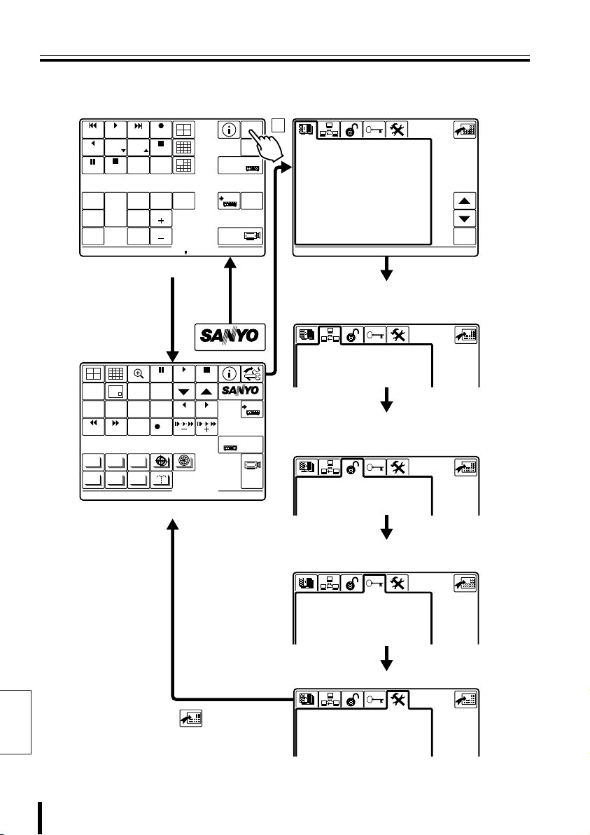
System Setup Overview
CAM 1 DVR 1
SYSTEM
PLAY
ALARM
PLAY
R PLAY
SPEED
PLAY STOP
STILL
SEQ
SEQ/
ON
PAN/
TOUR
PAN
OFF
ON
TOUR
ON
CAM 1 DVR 1
PLAY
SPEED
CLOCK
ADJUST
ONE PUSH
AF
FOCUS
FAR
FOCUS
NEAR
RECALARM
REC STOP
TIMER
ON/OFF
IRIS
CENTER
IRIS
IRIS
GO TO
PRESET
(Initial Screen)
ADDRESS ?
MUX
ADDRESS ?
SETUP
MAP
ENTER
DVR
TO SUB
SCREEN
1
b Select Language
Select the language displayed on the menu
display.
LANGUAGE
1-ITALIANO
> 2-ENGLISH
3-FRANÇAIS
4-DEUTSCH
5-********
6-********
7-********
8-********
9-********
10-********
11-********
12-********
ENABLED:
ENGLISH
ent
b Communication Setup
Sets up serial communication with the
equipment connected to the rear panel terminal.
English
MONITOR
2
SEARCH
TIMER
ALARM ALARM
AUTOPAN AUTOFLIP
PROG SCAN
PATR OL
SYSTEM
PLAY
STILL
MENU
EXIT/OSD
SEQUENCE
COPY
REC STOP REC
AUX
STOP
SYSTEM
ENTERCLEAR
MUX
DVR 1
1
(System Screen)
Press this button from each menu to
return to System screen.
COMMUNICATIONS
>1-VIDEO
2-TELEMETRY
3-SERIAL TESTS
b Control Setup
Sets up equipment and functions effective for
this unit.
ACCEPTED VALUES
>1-CAMERAS
2-MONITOR/LOCAL DVR-MUX
3-FUNCTIONS
b Password Setup
Sets up passwords.
PASSWORD
>1-AT SWITCHING ON
2-ALARMS RESET
3-PARAM. MODIFICATION
4-GRAPH ENVIR. LEVEL 1
5-GRAPH ENVIR. LEVEL 2
6-GRAPH ENVIR. LEVEL 3
b Setup
CONFIGURATION
>1-RESTORE BASIS VALUES
2-BUZZER/DISPLAY
3-JOYSTICK
4-TOUCH SCREEN SETTING
5-TOUCH TEST
41 System Setup
Page 43

Language Selection
ENGLISH
LANGUAGE
Passwords and menu display settings are available for operating this unit. As an
example, changing the language (LANGUAGE) is explained here. Use the same method
for other settings on the System screen.
SYSTEM
<Sub Screen>
MONITOR
TIMER
ALARM ALARM
AUTOPAN AUTOFLIP
PATR OL
2
SEARCH
PROG SCAN
MENU
SEQUENCE
REC STOP REC
AUX
1
LANGUAGE
1-ITALIANO
> 2-ENGLISH
3-FRANÇAIS
4-DEUTSCH
5-********
6-********
7-********
8-********
9-********
10-********
11-********
12-********
ENABLED:
ENGLISH
STILL
EXIT/OSD
COPY
Press the button.
1
The Main Menu appears.
Press the button.
2
The System screen language selection
screen is displayed.
Press the button or
3
button, select a language, then
SYSTEM
MUX
2
1
1
PLAY
STOP
ENTERCLEAR
DVR
press the button.
The language on the system screen
changes to the selected language.
2
Press the button.
4
Returns to the Sub screen.
3
4
ent
5
SETUP
ent
: These buttons cannot be operated
on this unit.
System Menu selection buttons
1
Pressing any button will display another
menu screen.
Press to return to the previous menu.
2
Press to move the cursor upward.
3
Press to move the cursor downward.
4
Press to confirm an item.
5
The next menu will appear.
English
System Setup 42
Page 44
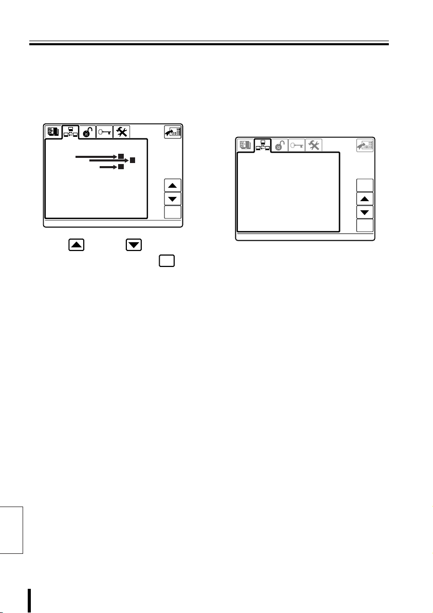
Communication Setup
COMMUNICATIONS
1-VIDEO
COMMUNICATIONS
This sets up communication with equipment connected to the video communication
terminal (VIDEO) or camera communication terminals (TELEMETRY A/B). Serial
communication testing between connected equipment is also available.
bbbb Select a communication item
(COMMUNICATIONS)
COMMUNICATIONS
>1-VIDEO
2-TELEMETRY
3-SERIAL TESTS
A
B
C
ent
Selection Items
A 1–VIDEO (Video Equipment
Communication Setup)
COMMUNICATIONS
1-VIDEO
>Type : DVR/MUX
Protocol : SANYO DVR/MU
Baudrate : 19200
Keyboard Add: 00001
esc
ent
Press the button or button to
select a setup item, then press the
button.
Displays the selected screen. See the
selection item (A B C).
English
ent
Upon purchasing, the communication settings
are set for connecting to our video equipment
(DVR/MUX), and the settings do not need to
be changed.
For communication setup for competitor video
equipment, see the “Communications Chart”.
(P86)
• Type:
This displays the equipment (DVR/MUX)
connected to the video communication
terminal. Changing the type will require
changing the Protocol and Baudrate as
well.
• Protocol:
This shows the communication protocol
(SANYO DVR/MU) used on this unit.
• Baudrate:
Select the data transmissions speed
(19200) for the connected video equipment.
• Keyboard Add:
This is the unit address.
43 System Setup
Page 45

Communication Setup
1-VIDEO
COMMUNICATIONS
00000
00004
00000
00003
00004
00000
1-VIDEO
COMMUNICATIONS
bbbb Unit Address Setup
When purchased, the unit address is set to
“1”. Change the address when using multiple
controllers.
Allocate addresses from 0 to 4.
* The addresses can also be checked using
the button.
COMMUNICATIONS
1-VIDEO
Type : DVR/MUX
Protocol : SANYO DVR/MU
Baudrate : 19200
>Keyboard Add: 00001
esc
ent
Changing the Unit Address
Press the button to select
1
“Keyboard Add”, then press
enter
the button.
The address setup screen appears, and
Datum “00000” will flash.
Press a number button
2
(example: 3), then press the
enter
button.
The communication setup screen
appears, and the address displays as 3.
Entry range: 0, 1, 2, 3, 4
Datum: 00003
00001
Accept.values
Max 00004
Min 00000
Digit
address
COMMUNICATIONS
1-VIDEO
Type : DVR/MUX
Protocol : SANYO DVR/MU
Baudrate : 19200
>Keyboard Add: 00003
123
456
78
.
esc
9
enter
0
del
esc
ent
esc
ent
Datum: 00000
00001
Accept.values
Max 00004
Min 00000
Digit
address
123
456
78
.
9
enter
0
esc
del
esc
ent
Note: When 5 or a higher number is entered,
a warning sounds and “Digit address”
displays “Datum not enabled”. Enter a
number within the input range.
: Returns to Communication Setup
esc
screen.
: Restores the input number to “0”.
del
System Setup 44
English
Page 46

Communication Setup (Continued)
2-TELEMETRY
COMMUNICATIONS
B 2–TELEMETRY
(Dome camera or zoom camera
communication setup)
COMMUNICATIONS
2-TELEMETRY
>A-Connector Video
A-Protocol SANYO SSP
A-Baudrate ---- B-Connector Telemetry
B-Protocol --------- B-Baudrate -----
esc
ent
Upon purchasing, the communication settings
are set to connect our video equipment to
cameras using coaxial cables.
Communication uses the video
communication terminal (VIDEO). For details,
see “A-Connector”.
bbbb Communication setup when using our
video equipment and cameras
• A-Connector:
Video: Connecting cameras via video
equipment.
Telemetry: Operating a camera by
• A-Protocol:
The communication protocol used on this
unit is SANYO SSP. Every time the
communication protocol is changed,
“A-Baudrate” is restored to the default
value.
• A-Baudrate:
Select the data transmissions speed for the
camera connected to camera
communication terminal A.
Note: When “Video” is selected for
connecting this unit to camera
using modular cable.
“A-Connector”, the Video data
transmission speed is fixed, and
“A-Baudrate” cannot be set.
bbbb Communication setup when using
competitor cameras
• B-Connector: Telemetry
Operating a camera by connecting this unit
to camera using modular cable.
• B-Protocol:
This is the communication protocol used on
this unit.
Every time the communication protocol is
changed, “B-Baudrate” is restored to the
default value.
• B-Baudrate:
Select the data transmissions speed for the
camera connected to camera
communication terminal B.
English
45 System Setup
Page 47
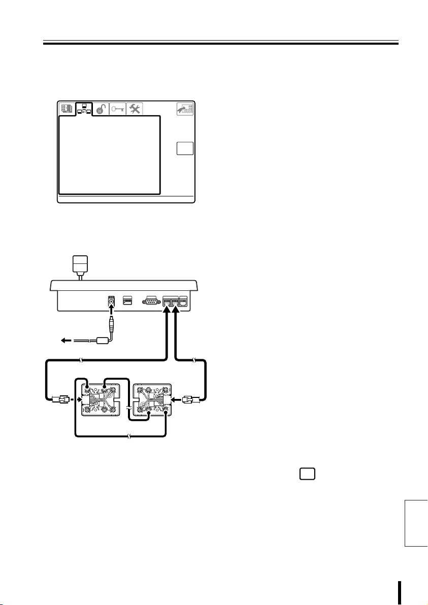
Communication Setup
3-SERIAL TESTS
V:
COMMUNICATIONS
C 3–SERIAL TESTS
(Communication output test for
video communication terminal and
camera communication terminal)
COMMUNICATIONS
3-SERIAL TESTS
Under test!!!
?? B:B:?? A:A:??
V:
? --------- ?
Remove all lines connected to this unit, and
use two modular cables and two
communication converter connectors to
connect as shown below.
1
234
ON
12V
White Yellow
G
R
B
R
S
L
Y
L
WH
B
L
O
R
B
K
R
D
R
D
G
R
Yellow
K
L
COMSW
O
R
B
Y
B
R
esc
TELEMETRY
VIDEO
AB
B
L
WH
S
L
White
Connect test cables to each
1
camera communication
terminal (TELEMETRY A and
B) on the rear panel.
Check the results displayed on
2
the menu display.
B<------>A:
Normal
B<------?A:
Line B has normal reception, but Line A
has a reception problem.
B?------>A:
Line A has normal reception, but Line B
has a reception problem.
When a problem is indicated, repeat the
test with TELEMETRY A connected to
VIDEO, and with TELEMETRY B
connected to VIDEO. The test results are
displayed as follows.
B?------?A:
The line is not functioning. No
transmission or reception.
B?------>A:
Transmission is possible, but no
reception.
B<------?A:
Reception is possible, but no
transmission.
B<------?A:
The line has normal transmission and
reception.
• When connecting V and A, or V and B,
this is displayed as follows.
V<------>A
V<------>B
When the test is complete,
3
press the button to return
esc
to the Menu screen.
English
System Setup 46
Page 48

Control Setup
ACCEPTED VALUES
1-CAMERAS
A A A A A A A A A A
A A A A A A
ACCEPTED VALUES
Dvr/Mux
001
Sets up equipment and functions effective for this unit.
bbbb Select a Control Item
(ACCEPTED VALUES)
ACCEPTED VALUES
>1-CAMERAS
2-MONITOR/LOCAL DVR-MUX
3-FUNCTIONS
Press the button or button to
select a setup item, then press the
button.
Displays the selected screen. See the
selection item (A B C).
A
B
C
ent
ent
Selection Items
A 1–CAMERAS
(Camera Communication Setup)
ACCEPTED VALUES
Dvr/Mux
001
1-CAMERAS
> 1 A A A A A A A A A A
11 A A A A A A
21
31
51
61
71
81
91
When purchased, the camera communication
terminal (TELEMETRY) is set to “A” output.
Set the camera connection terminal (A
connector, B connector, or not connected) for
the camera connected to each channel on the
hard disk digital recorder or the multiplexer
(Dvr/Mux).
Clear button
Disconnects all cameras.
A/B line switch button
Press the or button to
TEL TEL
change the button name. Pressing
this button switches the connection
terminal for all cameras.
Single row switch button
Press the or button to
TEL TEL
change the button name. Pressing
this button switches the connection
terminal for each row.
-
10
esc
DVR-MUX
-
1
DVR-MUX
DVR-MUX
+
1
DVR-MUX
TELTEL
+
10
ent
English
47 System Setup
Page 49

Control Setup
1-CAMERAS
A A A A A A A A A A
A A A A A A A A A A
A A A A A A A A A A
A A A A A A A A A A
A A A A A A A A A A
A A A A A A A A A A
A A A A A A A A A A
A A A A A A A A A A
A A A A A A A A A A
ACCEPTED VALUES
Dvr/Mux
001
2-MONITOR/LOCAL DVR-MUX
ACCEPTED VALUES
2-MONITOR/LOCAL DVR-MUX
ACCEPTED VALUES
Single row clear button
Clears a row at a time.
ACCEPTED VALUES
Dvr/Mux
001
1-CAMERAS
1 A A A A A A A A A A
> 11
21 A A A A A A A A A A
31 A A A A A A A A A A
41 A A A A A A A A A A
51 A A A A A A A A A A
61 A A A A A A A A A A
71 A A A A A A A A A A
81 A A A A A A A A A A
91 A A A A A A A A A A
Individual camera setup button
ent
The ten cameras on the cursor line
can be set (A/B/m) individually.
A line selection button
TEL
When pressed, the A/B line switch
button switches to the button.
B line selection button
TEL
When pressed, the A/B line switch
button switches to the button.
Address –10 button
-
10
The address of connected video
DVR-MUX
equipment (Dvr/Mux) is shifted
downward in increments of 10.
Address –1 button
-
1
The address of connected video
DVR-MUX
equipment (Dvr/Mux) is shifted
downward in increments of 1.
Address +1 button
DVR-MUX
+1
The address of connected video
equipment (Dvr/Mux) is shifted
upward in increments of 1.
Address +10 button
DVR-MUX
+10
The address of connected video
equipment (Dvr/Mux) is shifted
upward in increments of 10.
B 2–MONITOR/LOCAL DVR-MUX
(Valid/Invalid setup for hard disk
digital recorder with multiplexer
function)
-
10
esc
DVR-MUX
-
1
DVR-MUX
DVR-MUX
+
1
DVR-MUX
TELTEL
+
10
ent
ACCEPTED VALUES
2-MONITOR/LOCAL DVR-MUX
> 1
11
21
31
41
51
61
71
81
91
esc
ent
Set the addresses of connected video
equipment.
Clear button
Invalidates all video equipment.
All valid button
Validates all video equipment.
Single row switch button
Sets a row to be valid.
Single row invalidate button
Sets a row to be invalid.
Individual setup button
ent
The ten video equipment units on the
cursor line can be set (a/m)
individually.
ACCEPTED VALUES
2-MONITOR/LOCAL DVR-MUX
> 1
2
3
4
5
6
7
8
9
10
esc
ent
English
System Setup 48
Page 50

Control Setup (Continued)
3-FUNCTIONS
ACCEPTED VALUES
C 3–FUNCTIONS
ACCEPTED VALUES
3-FUNCTIONS
>1 -Mtx/Dvr/Mux setup..
2 -Telemetry setup....
3 -Autopan/Scan/Patrol
4 -Joystick...........
5 -Camera Up/Dw.......
6 -Address change.....
7 -Mon/Dvr/Mux change.
8 -Zoom/Focus/Iris....
9 -Aux................
10-Wiper/Washer.......
11-MAPS environment...
12-Spot Skip..........
esc
ent
Other functions can be started or stopped.
• Mtx/Dvr/Mux setup
Enables display of the video equipment
menu.
• Telemetry setup
Enables display of the camera menu.
• Autopan/Scan/Patrol
Enables automatic operation of dome
cameras.
• Joystick
Enables joystick operation.
• Camera Up/Dw
Moves camera input channel up and down.
(Function only available when matrix
multiplexer is connected.)
• Address change
Enables changing the camera address for a
hard disk digital recorder channel. When
ON, a camera icon is displayed in the upper
left of the camera address screen.
?
1
• MAPS environment
Displays a user-created map when power is
turned ON.
• Spot Skip
When the “MON2” video output for the hard
disk digital recorder is set to camera
sequence mode, images from the camera
being operated are not output from the
“MON2” video output terminal.
• Mon/Dvr/Mux change
Enables changing DVR-MUX address.
• Zoom/Focus/Iris
Enables changing zoom, focus, and iris
values for connected cameras.
English
• Aux
Enables Aux operation of connected
cameras.
• Wiper/Washer
Enables wipers and washers, special
functions of connected cameras.
49 System Setup
Page 51

PASSWORD
Password Setup (PASSWORD)
Passwords can be set for operations upon unit power ON, setup menu access, etc.
1-AT SWITCHING ON
PASSWORD
>1-AT SWITCHING ON
2-ALARMS RESET
3-PARAM. MODIFICATION
4-GRAPH ENVIR. LEVEL 1
5-GRAPH ENVIR. LEVEL 2
6-GRAPH ENVIR. LEVEL 3
ent
Password required upon power ON
Digit
password
Start
.
enter
0
2-ALARMS RESET
Password required upon alarm reset
Digit
password
Alarm reset
.
enter
0
3-PARAM.MODIFICATION
Password required upon accessing setup
menu
Digit
password
Parameters
.
enter
0
4-GRAPH ENVIR. LEVEL 1
Password required to enter Graphics
Environment Setup Level 1
Digit
password
Level 1
.
enter
0
5-GRAPH ENVIR. LEVEL 2
Password required to enter Graphics
Environment Setup Level 2
Digit
password
Level 2
.
enter
0
• Write down each password to
remember them. Also, periodic
password changes are recommended
for safety.
• When purchased, the password is set
to “00000”. When no password is
required, set it as “00000”.
• When the unit is initialized, all
passwords become “00000”.
6-GRAPH ENVIR. LEVEL 3
Password required to enter Graphics
Environment Setup Level 3
Digit
password
Level 3
.
enter
0
• When a password is set, an entry
screen will appear, requesting your
password (example: upon power ON).
Enter the password that is set.
• When the wrong password is entered,
“Password not enabled” is displayed.
Enter the correct password.
System Setup 50
English
Page 52

Password Setup (PASSWORD) (Continued)
PASSWORD
Password
enabled
The password setup procedure is the same for each item. Here, entering the password
upon unit power ON is explained.
bbbb AT SWITCHING ON
(Power ON password)
Press the button or
1
button to select “AT
SWITCHING ON”, then press
ent
the button.
PASSWORD
>1-AT SWITCHING ON
2-ALARMS RESET
3-PARAM. MODIFICATION
4-GRAPH ENVIR. LEVEL 1
5-GRAPH ENVIR. LEVEL 2
6-GRAPH ENVIR. LEVEL 3
The password entry screen appears, and
“-----” will flash.
-----
Digit
password
Start
123
456
78
.
esc
del
9
enter
0
ent
esc
ent
Press number buttons to enter
2
the password, (example:
12345), then press the
button.
“Digit” changes to “Confirm”, and
“*****” changes to “-----” (flashing).
-----
123
456
Confirm
password
Start
Press number buttons to enter
3
78
.
esc
del
9
enter
0
the password again for
confirmation (12345), then
press the button.
When “Password enabled” is displayed,
the process is complete. The
“PASSWORD” screen is displayed again.
*****
Password
enabled
Confirm
password
Start
enter
123
456
78
.
9
0
esc
del
enter
enter
esc
ent
esc
ent
English
51 System Setup
Page 53

Setup (CONFIGURATION)
Enter
ESC
1-RESTORE BASIS VALUES
2-BUZZER/DISPLAY
3-JOYSTICK
Y:
b Initialize b Buzzer and menu display setup
CONFIGURATION
1-RESTORE BASIS VALUES
>Confirm? (ENTER)
CONFIGURATION
>1-RESTORE BASIS VALUES
2-BUZZER/DISPLAY
3-JOYSTICK
4-TOUCH SCREEN SETTING
5-TOUCH TEST
ent
ent
CONFIGURATION
2-BUZZER/DISPLAY
>1-Key pressed : MAX
2-Joystick : YES
3-Serial error : YES
4-Matrix alarm : YES
5-Power saving : NO
b Joystick setup
CONFIGURATION
3-JOYSTICK
>1-Released
2-All at right
3-All at left
4-All up
5-All down
6-Rotate zoom at left
7-Rotate zoom at right
Max Cent. Min. D+ DX:00620 00500 00400 007 007
Y:00620 00500 00400 007 007
Z:00620 00500 00400 007 007
X:007 Y:
b Touch screen adjustmentb Touch screen test
007 Z:Z:007
*****
*****
00426
03557
ent
ent
Enter
ESC
English
System Setup 52
Page 54

Setup (CONFIGURATION) (Continued)
1-RESTORE BASIS VALUES
CONFIGURATION
1-RESTORE BASIS VALUES
CONFIGURATION
1-RESTORE BASIS VALUES
CONFIGURATION
2-BUZZER/DISPLAY
CONFIGURATION
bbbb Initialize
(RESTORE BASIS VALUES)
When this is set, the settings of each menu
screen revert to the default settings.
Press the button or
1
button to select “RESTORE
BASIS VALUES”, then press
ent
the button.
The “1–RESTORE BASIS VALUES”
screen is displayed.
CONFIGURATION
1-RESTORE BASIS VALUES
>Confirm? (ENTER)
2
English
Press the button.
After “>>...Restore <<“ is displayed,
“>>Restore performed<<” flashes and the
unit is initialized. After initialization is
complete, perform menu setup again.
CONFIGURATION
1-RESTORE BASIS VALUES
>Confirm? (ENTER)
>>... Restore <<
CONFIGURATION
1-RESTORE BASIS VALUES
>Confirm? (ENTER)
>>Restore performed<<
ent
esc
ent
esc
esc
bbbb Buzzer and menu display setup
(BUZZER/DISPLAY)
Press the button or
1
button to select “BUZZER/
DISPLAY”, then press the
ent
button.
The “2–BUZZER/DISPLAY” screen is
displayed.
CONFIGURATION
2-BUZZER/DISPLAY
>1-Key pressed : MAX
2-Joystick : YES
3-Serial error : YES
4-Matrix alarm : YES
5-Power saving : NO
esc
ent
Press the button or
2
button to select a setup item,
then press the button.
The selected setting value will flash.
Press the button or button to
switch the selected item.
Setup items:
• 1–Key pressed: Button operation
This setting sounds a buzzer when a
button on the screen is pressed.
Selections: MAX (loud), MIN (soft)
• 2–Joystick: Joystick Operation
This setting sounds a buzzer when the
joystick is moved.
Selections: YES, NO
• 3–Serial error: Serial error detection
This setting sounds a buzzer upon a
serial communication error.
Selections: YES, NO
ent
53 System Setup
Page 55

Setup (CONFIGURATION)
3-JOYSTICK
Max Cent. Min. D+ D-
Y:
Z:
X:
Z:
CONFIGURATION
• 4–Matrix alarm: Matrix alarm
detection
This setting sounds a buzzer when an
alarm is detected.
Selections: YES, NO
• 5–Power saving: Power save
function
When no buttons are operated for
approximately one minute, the screen
brightness is automatically switched
(dimmed).
When another button operation is
performed, the brightness returns to
normal.
Selections: YES, NO
Press the button.
3
ent
The selection item stops flashing, and the
setup is complete.
bbbb Joystick Setup (JOYSTICK)
Press the button or
1
button to select “JOYSTICK”,
007
ent
esc
ent
then press the button.
The “3–JOYSTICK” screen is displayed.
CONFIGURATION
3-JOYSTICK
>1-Released
2-All at right
3-All at left
4-All up
5-All down
6-Rotate zoom at left
7-Rotate zoom at right
Max Cent. Min. D+ DX:X:00620 00500 00400 007 007
Y:
00620 00500 00400 007 007
Z:
00620 00500 00400 007 007
007 Y:Y:007 Z:
X:
Press the button or
2
button to switch the joystick
setting position.
Setting positions:
Set in sequence, from number 1.
Each joystick position will be placed in
memory.
• 1–Released (Setting center position)
Press the button without
touching the joystick.
• 2–All at right
(Setting far right position)
Press the button with the joystick
tipped to the far right.
• 3–All at left (Setting far left position)
Press the button with the joystick
tipped to the far left.
• 4–All up (Setting topmost position)
Press the button with the joystick
tipped to the topmost position.
• 5–All down
(Setting bottommost position)
Press the button with the joystick
tipped to the bottommost position.
• 6–Rotate zoom at left
(Setting left zoom position)
Press the button with the joystick
rotated to the far left.
• 7–Rotate zoom at right
(Setting right zoom position)
Press the button with the joystick
rotated to the far right.
ent
ent
ent
ent
ent
ent
ent
When the wrong position was set
by mistake, move the cursor to the
mistaken setting and set it again.
English
System Setup 54
Page 56

Setup (CONFIGURATION) (Continued)
Enter
ESC
Enter
ESC
Enter
ESC
Enter
ESC
bbbb Touch screen adjustment
(TOUCH SCREEN SETTING)
Press the button or
1
button to select “TOUCH
SCREEN SETTING”, then
*****
*****
enter
00425
03590
Enter
ESC
press the button.
The adjustment screen appears.
Press the center of the
2
button at the upper left to
display the pressed
coordinates.
The “*****” changes to coordinates
(numerical value).
The coordinates are fixed.
Value when pressed Current adjustment value
English
00398
03516
Setting value guideline:
• Top line coordinate range: 300 – 600
• Bottom line coordinate range: 3400 – 3600
00524
03539
Enter
ESC
Press the button.
3
enter
The coordinates at the upper left are
placed in memory, and change to
“= = = = =”.
-----
-----
Press the button.
4
00524
03539
Enter
ESC
The button at the upper left moves
to the lower right.
*****
*****
Press the center of the
5
03604
00773
Enter
ESC
button to display the pressed
coordinates.
The “*****” changes to coordinates
(numerical value).
The coordinates are fixed.
Setting value guideline:
• Top line coordinate range: 3400 – 3600
• Bottom line coordinate range: 500 – 1000
55 System Setup
Page 57

Setup (CONFIGURATION)
ESC
SAVE
DOWNLOAD MODE
Firmware
DOWNLOAD MODE
Firmware
Press the button.
6
enter
The coordinates at the lower right are
placed in memory, and change to
“= = = = =”.
Press the button.
7
SAVE
The coordinates at the upper left and
lower right are in memory.
-----
-----
SAVE
03572
00737
ESC
When the coordinates are
memorized at dramatically offset
positions, this unit will not
function. Proceed to the settings in
“Touch Screen Initialization”.
bbbb Touch Screen Initialization and
Reset
Initialize the set coordinates, and set the
coordinates again.
Remove wiring and power
1
cables for all equipment
connected to this unit.
Turn dipswitch (SW1) ON.
2
SW
1
234
ON
Connect the power cable for
3
this unit.
The “DOWNLOAD MODE” screen is
displayed.
**************************************
**
** DOWNLOAD MODE
** **
** ...WAITING FOR A COMMAND **
** **
** Firmware
**************************************
Operate the joystick as shown
4
**
**
**
in the figure.
2
3
1
A “...reset touch” message is displayed,
and the touch screen is initialized.
**************************************
**
** DOWNLOAD MODE
** **
** ...WAITING FOR A COMMAND **
** **
** Firmware
**************************************
... reset touch
**
**
**
System Setup 56
English
Page 58

Setup (CONFIGURATION) (Continued)
Enter
ESC
After initializing, operate the
5
joystick as shown in the
drawing to perform touch
screen adjustment.
1
2
The touch screen adjustment screen appears.
Perform settings using the procedure on P55.
-----
-----
After setup is complete, the “DOWNLOAD
MODE” screen is displayed. Turn the
dipswitch (SW1) OFF.
00524
03539
Enter
ESC
bbbb Touch screen test
(TOUCH TEST)
Press the button or
1
button to select “TOUCH
TEST”, then press the
button.
The testing screen appears.
Keep your finger here to exit to
the menu.
Press the boxes on the test
2
screen.
is displayed in the pressed boxes.
Press all the boxes to check them.
Hold down the upper right box
3
to return to the
“CONFIGURATION” screen.
ent
English
57 System Setup
Page 59

Software
CONTENTS
2222 Software Configuration ............................... 59
2222 Connection and Software Installation........ 60
2222 System Setup (Setup) .................................. 61
2222 Language Setup (Language)....................... 68
2222 Graphics Environment Setup (Maps)......... 71
Page 60

Software Configuration
Use the software on the provided CD-ROM to perform various settings for this unit on
your PC.
System Setup (Setup) P61
System setup for this unit are performed on the PC. The setting contents
can be saved on the PC, making it efficient to manage differing settings,
set one setting on multiple system controllers, or apply the same
settings to all units.
Language Setup (Language) P68
This allows creating new display languages for the unit, or changing
individual words as desired.
Graphics Environment Setup (Maps) P71
By creating the screen graphics environment as desired, including the
opening screen and the operation screen button placement, the
operation screen can be simplified or operation can be restricted,
depending on the usage environment.
bbbb Operating Environment
• PC equipped with a serial port
• OS: Windows 9x/2000/XP
When the software font is not displayed in the correct location, or the icon size is too
big or too small, check that the PC (Windows) is using the following settings.
• Display colors: 256 or more
English
• Font size: Normal 100%
59 Software
Page 61

Connection and Software Installation
bbbb Install the Software
Insert the provided CD-ROM in
1
the CD-ROM drive on the PC,
open it, and click SETUP.EXE.
The next screen is displayed.
Follow the instructions on the
2
screen to install the software.
Three pieces of software are installed:
Keyboard Setup, Keyboard Language,
and Keyboard Maps.
bbbb Making Connections
Connect the PC connection
3
terminal (COM) on the rear
panel of the unit to the PC
serial port, using the computer
connection cable (provided).
Before connecting, make sure all
equipment is turned off, and disconnect
camera communication and video
communication cables.
COMSW
TELEMETRY
VIDEO
1
234
ON
Turn dipswitch (SW1) ON.
4
AB
To PC connection terminal
To serial port
SW
1
234
ON
PC
After the PC settings are complete,
always return SW1 to its OFF
position.
Connect the power source to
5
the unit, and turn ON the PC.
“DOWNLOAD MODE” appears on the
unit menu display.
Software 60
English
Page 62

System Setup (Setup)
Double-click
1
2
3
1 Menu
[File]
New: Create new system settings.
Open: Open existing settings.
Save: Save settings.
Save as: Save settings by another name.
Receive from keyboard:
Download unit settings to this software.
Send to keyboard:
Upload software settings to the unit.
COM Port:
Select the PC port number (1 to 9).
[Language]
Select the menu display language for this
software.
[Exit]
Exit the software.
[Info]
Display the software version.
2 Toolbar
Click these icons as a shortcut to performing
each operation.
: Create new system settings.
English
: Open existing settings.
: Save settings.
: Display a print preview of the settings list.
: Print a settings list.
: Exit the software.
3 Tabs
Click the tabs to switch between four
operation screens.
[General] (P62)
These allow language selection,
communication setup, buzzer setup, and
password setup.
[Cameras] (P64)
Set the camera connection terminal (A
connector, B connector, or not connected)
for the camera connected to each channel
on the hard disk digital recorder or the
multiplexer (Dvr/Mux).
[Monitor/Local Mux] (P66)
Set the number of connected video
equipment.
[Enabling] (P67)
Other functions can be started or stopped.
: Download unit settings to this software.
: Upload software settings to the unit.
61 Software
Page 63

System Setup (Setup)
A General (General Settings)
41
2
1
4
2 3
From the “File” menu, select
1
“New”.
• To open saved settings, select “Open”.
• To download the current unit settings
and change them, select “Receive from
keyboard”.
Click the [General] tab.
2
Make the various settings. (P63)
3
1 Language (Select Language)
2 Commnunications
(Communication Setup)
3 Buzzer/Display
(Buzzer and Menu Display Setup)
4 Password (Password Setup)
Make the various selections.
4
• To make other settings, switch using
the tabs and continue operation.
• To save settings in the PC, on the “File”
menu select “Save”.
• When selecting “Send to keyboard” on
the “File” menu, the system setup
content is uploaded to the unit.
English
Software 62
Page 64

System Setup (Setup) (Continued)
1 Language (Select Language):
Each number corresponds to the number by each
language displayed in the LANGUAGE screen under
System Setup ( ).
Check the display language and select the proper
number.
2 Communications
(Communication Setup):
bbbb When controlling a camera connected
to our video equipment (Video)
Upon purchasing, the communication settings are
set for connecting to our video equipment (DVR/
MUX), and the settings do not need to be changed.
For communication setup for competitor video
equipment, see the “Communications Chart”.
(P86)
• Type:
This displays the equipment (DVR/MUX)
connected to the video communication terminal.
Changing the type will require changing the
Protocol and Baudrate as well.
• Protocol:
This shows the communication protocol (SANYO
DVR/MU) used on this unit.
• BaudRate:
Select the data transmissions speed (19200) for
the connected video equipment.
• Address:
This is the unit address.
bbbb Communication setup when using our
video equipment and cameras
(Telemetry A)
Upon purchasing, the communication settings are
set to connect our video equipment to cameras using
coaxial cables.
Communication uses the video communication
terminal (VIDEO).
• Connector:
Connecting cameras via video equipment.
Video:
Telemetry:
Operating a camera by connecting
this unit to camera using modular
cable.
• Protocol:
The communication protocol used on this unit is
SANYO SSP. Every time the communication
protocol is changed, “Baudrate” is restored to the
English
default value.
• Baudrate:
Select the data transmissions speed for the
camera connected to camera communication
terminal A.
Note: When “Video” is selected for “Connector”, the
Video data transmission speed is fixed, and
“Baudrate” cannot be set.
63 Software
bbbb Communication setup when using
competitor cameras (Telemetry B)
• Connector: Telemetry
Operating a camera by connecting this unit to
camera using modular cable.
• Protocol:
This is the communication protocol used on this
unit.
Every time the communication protocol is
changed, “Baudrate” is restored to the default
value.
• Baudrate:
Select the data transmissions speed for the
camera connected to camera communication
terminal B.
3 Buzzer/Display
(Buzzer and Menu Display Setup):
Select and check the setup for each item.
• Key pressed: Button operation
This setting sounds a buzzer when a button on the
screen is pressed.
Selections: Min (soft), Max (loud)
• Joystick: Joystick Operation
This setting sounds a buzzer when the joystick is
moved.
Selections: No, Yes
• Serial error: Serial error detection
This setting sounds a buzzer upon a serial
communication error.
Selections: No, Yes
• Matrix Alarm:
Selections: No, Yes
• Power Saving:
Selections: No, Yes
4 Password (Password Setup):
Enter when setting a password for the following
items.
• Turn on: Upon power ON
• Reset Alarms: Upon alarm reset
• Change parameters: Upon accessing setup menu
• Level 1: Upon calling up “Level 1” functions
• Level 2: Upon calling up “Level 2” functions
• Level 3: Upon calling up “Level 3” functions
For level settings, see the “Jump page” on P75.
Page 65

System Setup (Setup)
B Cameras (Camera communication setup)
1
2
To change a camera address
connected to another Dvr/Mux,
change the Dvr/Mux address.
Click the [Cameras] tab.
1
Set camera lines using the
2
various buttons.
: Clear button
Disconnects all cameras.
: Single row clear button
Clears a row at a time.
: A/B line switch button
When pressed, all camera
connection terminals switch to A.
: Single row switch button
When pressed, a row of
connection terminals switch to A.
: A/B line switch button
When pressed, all camera
connection terminals switch to B.
: Single row switch button
When pressed, a row of
connection terminals switch to B.
Select a camera for
3
communication settings,
double-click it, and click the
button to display a menu.
Select the desired status.
Blank: Stop
A: Output from line A.
B: Output from line B.
The setting information is displayed in the
“Camera info” line at the bottom of the
screen. When the setting is blank,
“Disabled” is displayed.
English
Software 64
Page 66

System Setup (Setup) (Continued)
Changing the Camera Address
Number
• Click to enter input/output settings
mode (upper left grid displays “Addr.”).
To set a camera address, double-click it
and enter the number.
• To change the address of a camera
connected to another hard disk digital
recorder or multiplexer (Dvr/Mux), use the
spin button to change the Dvr/Mux address.
Make the various selections.
4
• To make other settings, switch using
the tabs and continue operation.
• To save settings in the PC, on the “File”
menu select “Save”.
• When selecting “Send to keyboard” on
the “File” menu, the system setup
content is uploaded to the unit.
English
65 Software
Page 67

System Setup (Setup)
C Monitor/Local Mux
(Valid/Invalid setup for hard disk digital recorder with multiplexer)
1
2
3
Click the [Monitor/Local Mux]
1
tab.
Set the video equipment
2
output using the various
buttons.
: Clear button
Invalidates all video equipment.
: Single row invalidate button
Sets a row to be invalid.
: All valid button
Validates all video equipment.
: Single row switch button
Sets a row to be valid.
For video equipment not
3
connected, turn the checkbox
OFF (blank).
Make the various selections.
4
• To make other settings, switch using
the tabs and continue operation.
• To save settings in the PC, on the “File”
menu select “Save”.
• When selecting “Send to keyboard” on
the “File” menu, the system setup
content is uploaded to the unit.
English
Software 66
Page 68

System Setup (Setup) (Continued)
D Enabling (stopping or starting settings)
1
2
English
Click the [Enabling] tab.
Check the functions to turn
ON.
Uncheck the functions to turn OFF,
leaving them blank.
• Setup Matrix/Dvr/Mux
Enables display of the video equipment
menu.
• Setup Telemetry
Enables display of the camera menu.
• Autopan/Scan/Patrol
Enables automatic operation of dome
cameras.
• Joystick
Enables joystick operation.
• Camera Up/Down
Moves camera input channel up and
down. (Function only available when
matrix multiplexer is connected.)
• Address change
Enables changing the camera address
for a hard disk digital recorder channel.
When ON, a camera icon is displayed
in the upper left of the camera address
screen.
?
1
• Mon/Dvr/Mux change
Enables changing DVR-MUX address.
• Zoom/Focus/Iris
Enables changing zoom, focus, and iris
values for connected cameras.
• Aux
Enables Aux operation of connected
cameras.
• Wiper/Washer
Enables wipers and washers, special
functions of connected cameras.
• Map Environment
Displays a user-created map when
power is turned ON.
Make the various selections.
3
• To make other settings, switch using
the tabs and continue operation.
• To save settings in the PC, on the “File”
menu select “Save”.
• When selecting “Send to keyboard” on
the “File” menu, the system setup
content is uploaded to the unit.
67 Software
Page 69

Language Setup (Language)
Double-click
1
2
3
1 Menu
[Text management]
Receive from keyboard:
Receives the current language from the
unit.
Load from file:
Opens language settings file.
Send to keyboard:
Uploads software language settings to the
unit.
Save on file:
Saves current language settings to a file.
Special characters:
Displays an input screen for special
characters.
COM Port:
Select the PC port number (1 to 9).
[Language]
Select the menu display language for this
software.
[Exit]
Exit the software.
[Info]
Display the software version.
2 Toolbar
Click these icons as a shortcut to performing
each operation.
: Download unit settings to this software.
: Upload software settings to the unit.
: Opens language settings file.
: Saves current language settings to a file.
: Displays an input screen for special
characters.
: Copy a word to the same row (one row
at a time)
: Exit the software.
3 Tabs
Click the tabs to switch the language numbers
(1 to 12) to the left and right of the language
window.
Click
Software 68
English
Page 70

Language Setup (Language) (Continued)
bbbb Creating Two Different English
Tabs
From the “Text management”
1
menu, select “Receive from
keyboard”.
Receives the current language
2
from the unit.
The receive status is displayed on the
screen, and the language is displayed
when receiving is complete.
Example:Creating Two Different English
3
4
Language Setups
Select Tab 2 (English) in
Window A, and Tab 7 in
Window B.
Select “SCAN: digit” in
Window A, and click .
“SCAN: digit” is copied to Window B.
English
Window A Window B
69 Software
Click “SCAN: digit”, and delete
5
“: digit”.
Enter “S” after “SCAN”, and
6
press Enter.
The word now reads “SCANS”.
Page 71

Language Setup (Language)
Use the same procedure to
7
change other words or change
them into symbols, creating
tabs with different English
wording.
Pressing will display the special
character input screen.
Enter the language name in the top row.
From the “Text management”
8
menu, select “Send to
keyboard”.
• This uploads these software language
settings to the unit.
• To save settings in the PC, on the “Text
management” menu select “Save on
file”.
• To select the created language, check
its number in the Setup software under
“General” – “Language”. (P62)
Software 70
English
Page 72

Graphics Environment Setup (Maps)
1
2
Double-click
3
1 Menu
[Project]
• New: Creates new graphics.
• Open: Opens an existing file.
• Save: Saves current settings.
• Save as:
Save settings by another name
• Receive from keyboard:
Downloads the current settings from the
unit.
• Send to keyboard:
Upload software settings to the unit.
• Print preview:
Display a print preview of the settings list.
• Print: Print a settings list.
• COM port:
Select the PC port number (1 to 9).
[Images]
• Import: Reads an image file.
• Change image:
Creates or changes the background
screen. (P82)
• Keys surround:
Emphasizes the outlines of buttons
placed on the screen.
• Import keys images:
Reads a button illustration.
• Delete keys:
Deletes all buttons currently on the
screen.
• Delete background:
Deletes background of selected screen.
[Language]
Select the menu display language for this
English
software.
[Exit]
Exit the software.
[Info]
Display the software version.
71 Software
2 Toolbar
Click these icons as a shortcut to performing
each operation.
: Create new system settings.
: Open existing settings.
: Saves current settings.
: Downloads the current settings from
the unit.
: Upload software settings to the unit.
: Reads an image file.
: Emphasizes the outlines of buttons
placed on the screen.
: Reads a button illustration.
: Creates or changes the background
screen. (P82)
: Deletes all buttons currently on the
screen.
: Deletes background of selected screen.
: Display a print preview of the settings list.
: Print a settings list.
: Exit the software.
3 Tabs
Click the tabs to switch between three
operation screens.
[Opening]
Setup of opening screen upon power ON (P72)
[Service]
Setup for screen displayed when a system
information screen button is pressed
(P72)
[Maps]
Create a map (P73)
SERVICE
i
Page 73

Graphics Environment Setup (Maps)
bbbb Display Telephone Number on
Opening Screen
From the “Project” menu,
1
select “New”.
The Opening screen appears.
Double-click
From the “Project” menu,
3
select “Send to keyboard”.
A dialog box is displayed for selecting the
upload screen. Check the “Service”
checkbox, and click the OK button. The
pasted image is uploaded.
Click the “Service” tab, click
2
“”, and select the image
file to read.
Saving settings on PC
From the “Project” menu, select “Save”.
English
Software 72
Page 74

Graphics Environment Setup (Maps) (Continued)
bbbb Map Screen Explanation
From the “Project” menu, select “New”.
1
The Opening screen appears.
Double-click
Click the [Maps] tab.
2
The left window displays Map 1, and the right window displays the General icon.
5
English
1 7
2
4
3
6G 89
73 Software
F
Page 75

Graphics Environment Setup (Maps)
1 Map Display
2 Map Selection
Click the up or down arrows on the spin button
to switch the map display screen.
Note: Maps 1 to 4 are basic displays for this
unit, and cannot be changed (Locked).
To allocate button functions, select
Map 5 to 30.
3 Map selection button
From the pull-down menu, select the map
number to register.
4 Joystick Function Selection
• Select whether to apply the unit joystick
function to the allocated map. Click the
appropriate radio button.
• Click the “Info” tab to display the “Joystick”
selection. Check it to select turning the
joystick ON or OFF.
5 Icon palette
Drag and drop a selected icon onto the map
display to paste the icon.
The following operations are available.
Cancel key: Deletes a key.
Copy key: Copies a key.
Glue key: Pastes the copied key.
Image:
Pastes another prepared image onto a
pasted key.
Properties:
Sets a function for the pasted key.
Click to display the “Allocation Setup
Screen (P75)”. Select whether to allocate
a button function.
6 Info tab
Select a button on the Map display to display
the button function and allocation information.
7 Icon scrollbar
This shows all icons available by category.
8 Keys tab
Displays the icon palette.
9 – button
Deletes a saved icon group displayed on the
pull-down menu bar.
F + button (Category)
Saves an icon group as a new category.
G Recycle Bin
• To paste a blank grey button, click any
position on the map display.
• Right-click the pasted icon to display a
pop-up menu.
• To add an icon to the icon palette, right-click
the mouse on the icon palette to display a
pop-up menu.
English
Software 74
Page 76

Graphics Environment Setup (Maps) (Continued)
(Allocation Setup Screen)
(1)
(5)
English
(2)
(3) (4)
(1) Matrix/Mux-Dvr
Allocates functions and selects video
equipment and cameras for operation.
(2) Movements
Allocates dome camera automatic
functions.
See Protocol Chart (Autopan/Patrol).
(P79, 80)
(3) Focus/Iris
Allocates camera focus and iris functions.
(4) Jump page
Allocates Map switching functions
(Password levels can be set to perform this
function).
(6)
(7)
(5) Aux
Allocates other camera functions.
(6) Wiper/Washer
Allocates wiper and washer functions.
(7) Save and exit
Click when allocation is complete.
This saves the settings and exits the
allocation setup screen.
To exit the allocation screen without
saving, click “Exit”.
75 Software
Page 77

Graphics Environment Setup (Maps)
bbbb Sample Equipment Allocation
A To allocate “Play” to the hard disk digital recorder (DVR) at address 1
3
1
2
4
Check “Mixed System”.
1
Check “Local Dvr”.
2
Check “Select Dvr”, and enter
3
“1” in the text box (input field).
Check “Dvr Functions”, and
4
select “Play” from the
pull-down menu.
Press “Save and exit” to exit
5
the screen.
Software 76
5
English
Page 78

Graphics Environment Setup (Maps) (Continued)
B Select the camera connected to CH16 of the hard disk digital recorder
(DVR) on address 2, and allocate “Autopan”.
3 4
1
2
5
1
2
3
4
English
Check “Mixed System”.
Check “Local Dvr”.
Check “Select Dvr”, and enter
“2” in the text box (input field).
Check “Select camera”, and
enter “16” in the text box.
77 Software
Under Movements, under
5
Autopan, click the radio button
by “Start”, and enter “0” in the
text box.
Press “Save and exit” to exit
6
the screen.
6
Page 79

Graphics Environment Setup (Maps)
C To switch the map display screen to Map 15
1
2
At the lower right of the
1
screen, by “Jump page”,
check “No.”, and enter “15” in
the text box.
Press “Save and exit” to exit
2
the screen.
English
Software 78
Page 80

Graphics Environment Setup (Maps) (Continued)
bbbb Protocol Chart (Autopan)
Protocol
------------------ 1..32 START MULTISEQUENCE (*) 1..32 START SALVO (*) 1..32 START SEQUENCE(*)
ELBEX 0..2 0 START AUTOPAN
ELMO 0 START AUTOPAN 0 STOP AUTOPAN
ENEO 0 START AUTOPAN 0 STOP AUTOPAN
ERNITEC 0 START AUTOPAN
FASTRAX 1..8 START AUTOPAN 1..8
JVC 0 START AUTOPAN 0 STOP AUTOPAN
MACRO 0 START AUTOPAN 0 STOP AUTOPAN 0 TOGGLE AUTOPAN
PANASONIC 0 START AUTOPAN 0 STOP AUTOPAN
PELCO
SAMSUNG 0 START AUTOPAN 0 STOP AUTOPAN
SANYO SSP 0 START AUTOPAN 0
SANYO HSSP 0 START AUTOPAN 0
SANTEC 1..8 START AUTOPAN 1..8
SENSORMATIC
STAR 0 START AUTOPAN 0 STOP AUTOPAN
VCL 0 START AUTOPAN 0 STOP AUTOPAN
VIDEOTEC 0 START AUTOPAN 0 STOP AUTOPAN 0 TOGGLE AUTOPAN
Number Function Number Function Number Function
0 START AUTOPAN
Start 1 Stop 2 Toggle 3
1 START AUTOPAN LEFT
2 START AUTOPAN RIGHT
(*) only with VKR Eneo matrix on video line
English
1
2
3
4
5
6
79 Software
Autopan
Patrol
Page 81

Graphics Environment Setup (Maps)
bbbb Protocol Chart (Patrol)
Protocol
------------------ 1..32 START TOUR (*) 0 STOP TOUR (*) 0 RESET TOUR(*)
ELBEX
ELMO 0..3 START SEQUENCE 1..4
ENEO 0 START PATROL 0 STOP PATROL
ERNITEC 0 START PATROL
FASTRAX 1..8
JVC 0..2 START PATROL 1..3
MACRO 0..1 START PATROL
PANASONIC START PATROL 0 STOP PATROL
PELCO 0 START PATTERN
SAMSUNG 0..3 0 START PATROL
SANYO SSP 0..1 0 START TOUR
SANYO HSSP 0..1 0 START TOUR
SANTEC 1..8
SENSORMATIC
STAR 0..5 START GROUP 1..6
VCL 1..5 START PATROL 1..4
VIDEOTEC 0..1 START PATROL
Number Function Number Function Number Function
9..12
9..12
1..4 START PATTERN 1..3
Start 4 Stop 5 Toggle 6
(0..3)
START TOUR 1..8
START PATTERN 1..4
(9..12)
(0..2)
STANDAR (0)
START PATROL S.A. (1)
1 START PATTERN 1
2 START PATTERN 2
3 START PATTERN 3
1 START SEQUENCE
1 START SEQUENCE
START TOUR 1..8
START PATTERN 1..4
(9..12)
4 START APPLE PEEL
FUNCTION
(0..5)
5 START LAST PATROL
STANDAR (0)
START PATROL S.A. (1)
0 STOP PATROL
0..1 STOP PATROL
STANDAR (0)
STOP PATROL S.A. (1)
0..3 0 STOP PATROL
1 STOP PATTERN 1
2 STOP PATTERN 2
3 STOP PATTERN 3
0 STOP GROUP
0 0 START TOUR
1 START SEQUENCE
0..1 STOP PATROL
STANDAR (0)
STOP PATROL S.A. (1)
0..1 TOGGLE PATROL
STANDAR (0)
TOGGLE PATROL S.A. (1)
0..1 TOGGLE PATROL
STANDAR (0)
TOGGLE PATROL S.A. (1)
(*) only with VKR Eneo matrix on video line
Software 80
English
Page 82

Graphics Environment Setup (Maps) (Continued)
bbbb Changing the Opening screen
to “SANYO”
From the “Project” menu,
1
select “New”.
The Opening screen appears.
Double-click
Pastes the selected “SANYO”
3
logo onto the opening screen.
From the “Project” menu,
4
select “Send to keyboard”.
A dialog box is displayed for selecting the
upload screen. Check the “Opening”
checkbox, and click the OK button. The
pasted image is uploaded.
2
English
Click the “” icon, and
select the image file to read.
Opening Screen
81 Software
Page 83

Graphics Environment Setup (Maps)
bbbb Create a map using the
graphics tool and display on
opening screen.
Opening Screen
From the “Project” menu,
1
select “New”.
The Opening screen appears.
From the “Images” menu,
2
select “Change image”.
A paint screen (FPaint) is displayed.
Create a map or other graphic using the
graphics tool.
Software 82
English
Page 84

Graphics Environment Setup (Maps) (Continued)
Click to save settings.
3
From the “Project” menu,
4
1
select “Send to keyboard”.
A dialog box is displayed for selecting the
upload screen. Check the “Maps”
checkbox, and click the OK button. The
pasted image is uploaded.
3
1 General Tools
: Cancel the entire drawing.
: Cancel the previous operation (UNDO).
: Delete the item selected with the
cursor.
: Display a grid or crosses for estimating
the position.
Check the pattern of your choice.
Close up: Grid (displayed on top of item)
Crosses: Display crosses.
Snap: Grid (displayed underneath item)
Zoom: Selects the display magnification.
: Saves the image and exits “FPaint”.
2
4
Saving settings on PC
From the “Project” menu, select “Save”.
English
83 Software
: Exits “FPaint” without saving the image.
2 Color/Background Tools
: Selects white (When drawing on top of
background pattern, etc.).
: Selects black
:
Selects a background pattern
(Becomes background when drawing
with , , or .)
Page 85

Graphics Environment Setup (Maps)
3 Drawing Tools
: Selects the item (cursor)
: Draws lines freehand
: Draws straight line
: Draws rectangle (outline only)
: Draws solid rectangle
: Draws rectangle with rounded corners
(outline only)
: Draws solid rectangle with rounded
corners
: Draws circle (outline only)
: Draws solid circle
: Specifies character insertion position
(Characters are input into the text input
area first)
4 Text input area
Sets characters, font, size, and
embellishments (Bold, Italic, Underline).
Characters are positioned in the area
specified using the cursor.
bbbb Basic Graphics
6
2
3
5
Select the color to use
1111
To draw white lines, click “”. To draw
black lines, click “”.
Draw lines
2222
To draw lines freehand, click “”. To
draw straight lines, click “”.
Draw shapes
3333
Click , , or other buttons.
Fill shapes with patterns
4444
Click “” or “”, then “” or other
buttons.
1
4
Draw characters
5555
Input characters, select the font and size,
then click “”.
Move or delete shapes or lines
6666
• Move:
Click “”, then select and move a
shape.
• Delete:
Click “”, then select and move a
shape to the Recycle Bin.
Software 84
English
Page 86

Specifications
Communication Method RS485
Keyboard Backlight LCD, 320 x 240 touch screen
Joystick Three-axis joystick (pan/tilt/zoom)
Control terminal RJ-11 terminal: VIDEOx1, TELEMETERYx2
RS-232C terminal for PC D-SUB (9-pin): 1 terminal
Dipswitch • Normal mode/PC mode: 1-bit dipswitch
• Terminate: 3-bit dipswitch (Video/Telemetry A/B)
Communication speed 2400, 4800, 9600, 19200 bps
Maximum number of
connected equipment
Usage conditions Temperature: 5°C to 40°C
Storage conditions Temperature: –20°C to 60°C
Power source
(AC adapter)
Current consumption 1A
Weight 900g
Total: 256 units
• Controller: 5 units
• Multiplexer, hard disk digital recorder: 100 units total
• Dome camera, CCD camera: TELEMETRY A 127 units
TELEMETRY B 127 units
• Dome camera: 64 units
Humidity: 80% or less
Humidity: 80% or less
Input voltage: 100 – 240 V AC 50/60Hz
Output voltage: 12 V DC
Appearance and specifications may be revised without notice. Thank you for your understanding.
bbbb Outer Dimensions (Units: mm)
280
225
67
94
English
85 Others
Page 87

Appendix
bbbb Communications Chart
1–VIDEO (Video Line)
Type DVR/MUX
Protocol SANYO DVR/MU
Baudrate 19200
Type Protocol Baudrate
DVR/MUX SANYO DVR/MU 2400, 4800, 9600, 19200
- - - - - - - - - - - - - - - - - - - - - - - - - - - - - - - - - - - - - - - - - 4/2 VIDEOTEC MACRO
MACRO NO P.
8/2 VIDEOTEC MACRO
MACRO NO P.
8/4 VIDEOTEC MACRO
MACRO NO P.
16/4 VIDEOTEC MACRO
VIDEO TEC
MACRO NO P.
32/8 VIDEOTEC MACRO
VIDEOTEC
MACRO NO P.
128/16 VIDE. MACRO
MACRO NO P.
1200, 9600, 19200, 38400
1200, 9600, 19200, 38400
1200, 9600, 19200, 38400
1200, 9600, 19200, 38400
1200, 9600, 19200, 38400
1200, 9600, 19200, 38400
1200, 9600, 19200, 38400
300, 1200, 2400, 9600
1200, 9600, 19200, 38400
1200, 9600, 19200, 38400
9600
1200, 9600, 19200, 38400
1200, 9600, 19200, 38400
1200, 9600, 19200, 38400
Others 86
English
Page 88

Appendix (Continued)
2–TELEMETRY A (Camera Line)
Connector Protocol Baudrate
Video
Video SANYO SSP
VideoVideo
A-CONNECTOR Video
A-PROTOCOL SANYO SSP
A-Baudrate -----
Telemetry
Telemetry SANYO SSP
TelemetryTelemetry
A-CONNECTOR Telemetry
A-PROTOCOL SANYO SSP
A-Baudrate 19200
2–TELEMETRY B (Camera Line)
Connector Protocol Baudrate
Telemetry
Telemetry - - - - - - - - - - - -
TelemetryTelemetry
B-CONNECTOR Telemetry
B-PROTOCOL PELCO
B-Baudrate 19200
SANYO HSSP
SANYO HSSP
SANYO HSSPSANYO HSSP
When any other protocol is selected, the connector is
automatically displayed as “Telemetry”.
SANYO SSP
SANYO SSPSANYO SSP
SANYO HSSP
SENSORMAT.
VCL
VIDEOTEC
- - - - - - - - - - - ERNITEC
MACRO
MARK M.
PELCO
ERNITEC
MACRO
MARK
PELCO
PELCO
PELCOPELCO
SANYO SSP
SANYO HSSP
SENSORMAT.
VCL
VIDEOTEC
- - - - - - - -
- - - - - - - -
- - - - - - - -
- - - - - - - -- - - - - - - -
2400, 4800, 9600, 19200
19200
1920019200
2400, 4800, 9600, 19200
4800
9600
1200, 9600
- - - - - - - - - - - 1200, 2400, 4800, 9600, 19200, 38400
1200, 9600, 19200, 38400
9600
2400, 4800, 9600, 19200
- - - - - - - - - - - 1200, 2400, 4800, 9600, 19200, 38400
1200, 9600, 19200, 38400
9600
2400, 4800, 9600, 19200
19200
1920019200
2400, 4800, 9600, 19200
2400, 4800, 9600, 19200
4800
9600
1200, 9600
English
87 Others
Page 89

Appendix
TOUR
FOCUS
IRIS
CAM 1 DVR 1
bbbb Message Chart
ALARM: Esc to exit PATROL: Sent 'Walk' Stop
AUX: Select function PATROL: Sent Recording "Walk" nr.
AUX: Function not available PRESET: Select function
AUX: Function not enabled PRESET: Sent Delete preset position
AUX: Sent Set PRESET: Esc to exit
AUX: Sent Reset PRESET: Sent Preset command
AUX: Sent Toggle PRESET: Sent Delete Preset
AUTOFLIP: Function not available PRESET MARK M.: Esc to exit
AUTOFLIP: Function not enabled PRESET MARK M.: Select function
AUTOFLIP: Sent enabled Autoflip SCAN: Function not enabled
AUTOFLIP: Sent Autoflip toggle SCAN: Esc to exit
AUTOFLIP: Sent Autoflip set SCAN: Sent Scan command
AUTOFLIP: Sent Autoflip reset SCAN: Sent Home
AUTOFLIP: Select function SCAN: Sent Home (Scan at posit.nr.1)
AUTOPAN: Select function SCAN: Sent "Back"
AUTOPAN: Sent Autopan Start SEQUENCE: Sent sequence
AUTOPAN: Sent Autopan Stop SETUP: Select function
AUTOPAN: Sent Autopan Toggle SETUP: Sent Line Lock increment
AUTOPAN: Function not enabled SETUP: Sent Line Lock decrement
AUTOPAN: Function not available SETUP: Sent Enabled alarm mode
CAMERA: Esc to exit SETUP: Sent Disabled alarm mode
CAMERA: Recall camera nr. SETUP: Sent Home position storage
CAMERA: Camera not enabled! SETUP: Sent Home position reset
CAMERA: Sent command SETUP: Sent Toggle Mono/Color
DOME: Sent 'camera setup' SETUP: Sent Auto Mono/Color
DOME: Sent 'dome setup modification' SETUP: Sent V- phase+
DOME: Sent 'dome setup exit' SETUP: Sent V- phaseDOME: Sent 'Enter Menu' SETUP: Esc to exit
DOME: Function selection SETUP: Sent receiver Reset
DOME: Sent 'Move Up' TELEMETRY LINE "A": BUSY/ERROR
DOME: Sent 'Move Down' TELEMETRY LINE "B": BUSY/ERROR
DOME: Sent 'Move Left' LINE "VIDEO": BUSY/ERROR
DOME: Sent Move Right' VIDEO: Function not enabled
FOCUS: Function not enabled VIDEO: Sent camera increase
FOCUS: Select function VIDEO: Sent camera decrease
FOCUS: Sent Focus Near VIDEO: Function not available
FOCUS: Sent Focus Far VIDEO: Sent matrix sequence start
FOCUS: Sent AutoFocus VIDEO: Monitor not enabled!
FOCUS: Sent disabled AutoFocus VIDEO: Recall monitor nr.
IRIS: Function not enabled VIDEO: Sent 'Up Arrow'
IRIS: Select function VIDEO: Sent 'Do wn Arrow'
IRIS: Sent Iris Open VIDEO: Sent 'SEQ'
IRIS: Sent Iris Close VIDEO: Sent 'Matrix setup modification'
IRIS: Sent AutoIris VIDEO: Select function
IRIS: Sent disabled AutoIris VIDEO: Sent number
PATROL: Sent Start S.A. VIDEO: Sent 'M/A'
PATROL: Sent Toggle S.A. VIDEO: Sent 'STP'
PATROL: Function not enabled VIDEO: Sent 'CRL'
PATROL: Select function VIDEO: Sent 'ENT'
PATROL: Sent Start VIDEO: Unit not enabled
PATROL: Sent Stop VIDEO: Recall unit nr.
PATROL: Sent Toggle VIDEO: Dvr not enabled
PATROL: Sent enabled Pattern VIDEO: Mux not enabled
PATROL: Sent Pattern Definition VIDEO: Recall Dvr nr.
PATROL: Sent Pat.Defin ition End VIDEO: Recall Mu x nr.
PATROL: Sent Apple peel VIDEO UNIT: Sent command
PATROL: Sent standard Setup WIPER/WASHER: Functions not available
PATROL: Sent default pause time WIPER/WASHER: Function not enabled
PATROL: Sent Start/End WIPER/WASHER: Select function
PATROL: Sent single pause time WIPER/WASHER: Sent Wiper
PATROL: Sent Start 1 WIPER/WASHER: Sent Washer
PATROL: Sent Start 2 MATRIX TIMEOUT ALARM
PATROL: Sent Start 3 MATRIX ALARM
PATROL: Sent Start 4 MONITOR: Esc to exit
PATROL: Sent position ZOOM: Function not enabled
PATROL: Esc to exit JOYSTICK: Function not enabled
PATROL: Sent "SEQUENCE" DVR/MUX: Function not enabled
PATROL: Sent "TOUR" DVR: Esc to exit
PATROL: Sent 'One Pass' Start MUX: Esc to exit
PATROL: Sent 'Walk' Start nr. Esc to exit
Message display
ON
CAM 1 DVR 1
NEAR
ADDRESS ?
English
Others 88
Page 90

Appendix (Continued)
bbbb Special Code Chart
These functions can be loaded by entering their special codes.
ERNITEC SATURN............................................ 89
MARK MERCER ................................................ 90
PELCO .............................................................. 92
SENSORMATIC................................................. 94
ERNITEC SATURN
bbbb
Code Function
AUTOPAN
301 Saves the current position of the first limit switch.
302 Saves the current position of the second limit switch.
XXX XXX= 0 – 255: Auto-pan speed (0=min, 255=max)
PATROL
1000 Deletes patrol order.
1XXX XXX= 1– 128: Writes preset position “XXX” into patrol order.
2000
2XXX
3XXX X= 000 – 255: Waiting time (in seconds) upon reaching specified position
OTHER FUNCTIONS
4XXY Dome cameras can be set to automatically move to the "return position" after a
4000 Invalidates movement to “return position”.
400 Text display/non-display (switch)
500 Backlight compensation ON/OFF (switch)
9999 Initializes the dome camera internal memory.
Note: Cannot use with Saturn type.
Makes patrol order valid.
X= 001 – 128: Deletes preset position “XXX” from patrol order.
Example:
“1000” Deletes previously defined order.
“1001” Writes preset position “1” into order.
“1005” Writes preset position “5” into order.
“1006” Writes preset position “6” into order.
“2005” Deletes preset position “5”.
set stopping time passes.
XX= 01 – 99: “Return position” (Cannot select positions No. 100 to No. 128)
Y= 0 – 9: Return time
0: 10 seconds, 1: 20 seconds, 2: 30 seconds, 3: 40 seconds, 4: 1 minute,
5: 2 minutes, 6: 5 minutes, 7: 10 minutes, 8: 20 minutes, 9: 40 minutes
Example:
“4216”: After stopping for 5 minutes (Y=6), move to position 21 (XX=21).
English
89 Others
Page 91

Appendix
bbbb MARK MERCER
IRIS MANUAL
11 Opens the iris.
12 Closes the iris.
ON SCREEN DISPLAY
21 Screen display ON.
22 Screen display OFF.
23 Screen display on top half of monitor.
24
INFRARED RESPONSE CURVES
31 Initially set curve (visible light)
32 950nm curve
33 850nm curve
COLOUR/B&W CAMERA
40 Automatically switch from color to black-and-white, and black-and-white to color.
41 Black-and-white camera
42 Color camera
43 Decreases the camera integration level (decreases shutter speed).
44 Increases the camera integration level (increases shutter speed).
45 Zero lux ON (infrared filter OFF)
46 Zero lux OFF (infrared filter ON)
47 Brighter
48 Initial setting value
49 Darker
PRIVACY ZONE
51 All zones ON
52 All zones OFF
53 Switches zone-specific cursor (ON/OFF)
54 Switches masking (ON/OFF) depending on cursor status.
DYNAMIC CONTROL OF ZONE TITLING
61 Switches title (ON/OFF).
62 Deletes zone.
63 Initializes zone.
DIGITAL ZOOM
6 Switches to digital zoom (ON/OFF).
1XX
Code Function
Screen display on bottom half of monitor.
Switch level
Cursor ON: This code enables placing a small masking on the cursor. When the
Cursor OFF: This code enables masking the entire screen. When the code is
XX= 00 – 99
code is sent again, the masking type changes.
sent again, the masking is cancelled.
: Digital zoom value (when this function can be used for dome cameras).
Others 90
English
Page 92

Appendix (Continued)
Code Function
TOGGLE AUTO PARK (ON/OFF)
2XX Dome cameras can be set to automatically move to preset position No. 1 after a
set stopping interval passes.
XX= 01 – 99(*): Waiting time (minutes) before automatically stopping
(*) when waiting time XX=00, the function is invalid.
Example:
“205” Automatically stop after waiting for 5 minutes (XX=05)
“200” Automatic stop OFF (XX=00)
TOGGLE AUTO PATROL (ON/OFF)
1XXY Dome cameras can be set to automatically start the specified patrol order after a
OTHERS
0 Patrols all positions
1 Switches automatic U-turn (ON/OFF).
2 Aux 1 ON
3 Aux 1 OFF
7 Installed alarm: ON
8 Installed alarm: OFF
10
set stopping time passes.
XX= 01 – 99(*): Waiting time (minutes) before automatic patrolling.
Y= 0 – 5: Patrol number
(*) when waiting time XX=00, the function is invalid.
Example:
“1153” After stopping for 15 minutes (XX=15), automatically patrols in No. 3
(Y=3) patrol order.
“1003” Automatic patrol OFF (XX=00)
U-turn
English
91 Others
Page 93

Appendix
bbbb PELCO
0 Pan 0 position
SPEED CURVES
11 First speed curve (speed values: 1, 5, 10, 20, 30, 45, 63).
12 Second speed curve (speed values: 1, 10, 20, 30, 40, 50, 63).
13 Third speed curve (speed values: 10, 15, 20, 25, 30, 45, 63).
14 Fourth speed curve (default setting) (speed values: 29, 37, 45, 50, 55, 59, 63).
15 Fifth speed curve (speed values: 10, 15, 20, 30, 40, 50, 63).
16
8XXX X= 000 – 255: Speed value (*)
900X X= 1 – 7: Speed number. Values can be allocated.
910X X= 1 – 7: Dome camera operation test at No. X uniform speed.
(*) The Pelco D protocol accepts a value of 63 at maximum speed. Correct operation is not
ZONE
20 Begins zone scan.
21 Ends zone scan.
10X X= 1 – 8: Sets beginning of zone.
20X X= 1 – 8: Sets end of zone.
LENSES
40 Auto-focus ON
41 Auto-focus OFF
42 Automatically turn auto-focus ON
AUTOIRIS
50 Auto iris ON
51 Auto iris OFF
52 Automatically turn auto iris ON
ON SCREEN INFORMATION
60 Automatic gain control device ON
61 Automatic gain control device OFF
62 Automatic gain control device AUTO
Code Function
Sixth speed curve (Can be user customized, but has default settings:
10, 15, 20, 30, 55, 100, 255). (*)
To stop the test, move the joystick.
Example:
“8007”: Speed value equal to 7 (X=007)
“9001”: The 7 speed value is allocated to Speed No. 1 (X=1).
... Writes speed value into speed No. 2, 3, 4, 5, 6, etc.
“8138”: 138 (X=138) speed value
“9007”: Allocates speed value 138 to speed No. 7 (X=7).
To test speed No. 7 next:
“9107”: Dome camera moves at uniform speed of 138 (X=7).
“16”: Hereafter, whenever the joystick is moved, the dome camera moves at
the speed allocated to the sixth speed curve (X=16).
guaranteed when set at a higher speed.
English
Others 92
Page 94

Appendix (Continued)
Code Function
ALARMS
X Alarm identification (X is 1 to 8)
MISC
99 Cleans screen.
999 Initializes remote camera operations (pan/tilt).
9999 Initializes remote camera operations (to default values).
70 Backlight compensation ON
71 Backlight compensation OFF
80 White balance ON
81 White balance OFF
90 Makes “unit phase delay mode” valid.
3X X= 1 – 8: Zoom speed
13X X= 1 – 8: Focus speed
1000(*) Shutter speed
1001(*) Line lock level
1002(*) White balance R-B adjustment
1003(*) White balance M-G adjustment
1004(*) Gain
1005(*) Auto iris level
1006(*) Auto iris vertex
(*) After writing the code, a numerical value between 0 and 4000 must be introduced.
English
93 Others
Page 95

Appendix
bbbb SENSORMATIC
RELAYS
0 All relays OFF
1 Relay 1 ON
2 Relay 2 ON
3 Relay 3 ON
4 Relay 4 ON
12 Relay 1 and 2 ON
13 Relay 1 and 3 ON
14 Relay 1 and 4 ON
23 Relay 2 and 3 ON
24 Relay 2 and 4 ON
34 Relay 3 and 4 ON
123 Relay 1, 2 and 3 ON
124 Relay 1, 2 and 4 ON
134 Relay 1, 3 and 4 ON
234 Relay 2, 3 and 4 ON
1234 Relay 1, 2, 3 and 4 ON
PATTERN
51 Begins collection pattern 1.
52 Begins collection pattern 2.
53 Begins collection pattern 3.
55 Checks new pattern, and replaces the previous definition.
56 Ends pattern collection.
61 Begins pattern 1.
62 Begins pattern 2.
63 Begins pattern 3.
71 Deletes pattern 1.
72 Deletes pattern 2.
73 Deletes pattern 3.
MISC.
9999 Initializes remote camera operation
Code Function
Example:
“13”: Makes only relays 1 and 3 valid (Relays 2 and 4 are invalid).
“134”: Makes only relays 1, 3 and 4 valid (Relay 2 is invalid).
Example:
Definition of Pattern 2:
“72”: Delete old pattern 2 (relates to apple-peel function)
“52”: Begins collection of pattern 2. The dome camera moves within the display
limits.
“56”: Ends collection.
“55”: Replaces old pattern with new record.
“62”: Begins pattern 2.
English
Others 94
Page 96

1AC6P1P2951-L8CSC/WA (0805KP)a VTECH
SANYO Electric Co., Ltd.
 Loading...