

INSTRUCTION MANUAL
System controller
VSP-7000
About this manual
Before installing and using this unit, please read this manual
•
carefully. Be sure to keep it handy for later reference.
This manual gives basic connections and operating
•
instructions.
(XE)

PRECAUTION
WARNING: TO REDUCE THE RISK OF FIRE OR
ELECTRIC SHOCK, DO NOT EXPOSE THIS
APPLIANCE TO RAIN OR OTHER MOISTURE.
To avoid electrical shock, do not open the cabinet.
Refer servicing to qualified personnel only.
If the power supply cord (AC power cord) of this
appliance is damaged, it must be replaced. Return to a
SANYO Authorized Service Centre for replacement of
the cord.
Location
For safe operation and satisfactory performance of your system
controller, keep the following in mind when selecting a place for
its installation:
Shield it from direct sunlight and keep it away from sources of
•
intense heat.
Avoid dusty or humid places.
•
Avoid places with insufficient ventilation for proper heat
•
dissipation. Do not block the ventilation holes at the top and
bottom of the system controller. Do not place the unit on a
carpet because this will block the ventilation holes.
Install the system controller in a horizontal position only.
•
Avoid locations subject to strong vibrations.
•
Avoid moving the system controller between cold and hot
•
locations.
Do not place the system controller directly on top of a monitor
•
TV, as this may cause playback or recording problems.
Avoiding Electrical Shock and Fire
Do not handle the power cord with wet hands.
•
Do not pull on the power cord when disconnecting it from an
•
AC wall outlet. Grasp it by the plug.
If any liquid is spilled on the system controller, unplug the
•
power cord immediately and have the unit inspected at a
factory-authorized service centre.
Do not place anything directly on top of this system controller.
•
SERVICE
This unit is a precision instruments and if treated with care, will
provide years of satisfactory performance. However, in the event
of a problem, the owner is advised not to attempt to make
repairs or open the cabinet. Servicing should always be referred
to your dealer or Sanyo Authorized Service Centre.
CAUTION
Danger of explosion if battery is incorrectly replaced.
Replace only with the same or equivalent type
recommended by the manufacturer.
Discard used batteries according to the manufacture’s
instructions.
1
CONTENTS MAIN FEATURES
PART NAMES . . . . . . . . . . . . . . . . . . . . . . . . . . . . . . . . . . . . . . 3
Operation panel . . . . . . . . . . . . . . . . . . . . . . . . . . . . . . . . . . . . . .3
Rear panel . . . . . . . . . . . . . . . . . . . . . . . . . . . . . . . . . . . . . . . . . .4
CONNECTING THE VSP-7000 . . . . . . . . . . . . . . . . . . . . . . . . . 5
Basic setup . . . . . . . . . . . . . . . . . . . . . . . . . . . . . . . . . . . . . . . . . .5
Number of devices that can be connected . . . . . . . . . . . . . . . .6
MENU SETTINGS . . . . . . . . . . . . . . . . . . . . . . . . . . . . . . . . . . . 7
Displaying the menu screen . . . . . . . . . . . . . . . . . . . . . . . . . . . .7
SETTING THE DATA AND TIME . . . . . . . . . . . . . . . . . . . . . . . . 8
SETTING DAYLIGHT-SAVING TIME (summer time) . . . . . . . 9
SETTING THE SECURITY LOCKS . . . . . . . . . . . . . . . . . . . . . 10
Simple locks . . . . . . . . . . . . . . . . . . . . . . . . . . . . . . . . . . . . . . . .10
Deactivating the lock . . . . . . . . . . . . . . . . . . . . . . . . . . . . . . . . .10
TIMER LOCK . . . . . . . . . . . . . . . . . . . . . . . . . . . . . . . . . . . . . . .11
SETTING THE COMMUNICATION SPEED . . . . . . . . . . . . . . 12
SETTING THE TITLE . . . . . . . . . . . . . . . . . . . . . . . . . . . . . . . . 13
CHECKING THE GROUP SETTINGS . . . . . . . . . . . . . . . . . . . 14
MULTIPLEXER OPERATION . . . . . . . . . . . . . . . . . . . . . . . . . 15
[A] Operation using the command buttons . . . . . . . . . . . . . . . . .15
Operating procedure . . . . . . . . . . . . . . . . . . . . . . . . . . . . . . . . .15
Checking the address . . . . . . . . . . . . . . . . . . . . . . . . . . . . . . . .15
Command button operation list . . . . . . . . . . . . . . . . . . . . . . . .16
Operations . . . . . . . . . . . . . . . . . . . . . . . . . . . . . . . . . . . . . . . . .16
[B] Operation using the call-up commands . . . . . . . . . . . . . . . . .17
Operating procedure . . . . . . . . . . . . . . . . . . . . . . . . . . . . . . . . .17
Call-up Command Operation List . . . . . . . . . . . . . . . . . . . . . . .17
Operations . . . . . . . . . . . . . . . . . . . . . . . . . . . . . . . . . . . . . . . . .17
TIMELAPSE VCR OPERATION . . . . . . . . . . . . . . . . . . . . . . . 18
[A] Operation using the command buttons . . . . . . . . . . . . . . . . .18
Operating procedure . . . . . . . . . . . . . . . . . . . . . . . . . . . . . . . . .18
Checking the address . . . . . . . . . . . . . . . . . . . . . . . . . . . . . . . .18
Command Button Operation List . . . . . . . . . . . . . . . . . . . . . . .19
Operations . . . . . . . . . . . . . . . . . . . . . . . . . . . . . . . . . . . . . . . . .19
[B] Operation using the call-up commands . . . . . . . . . . . . . . . . .20
Operating procedure . . . . . . . . . . . . . . . . . . . . . . . . . . . . . . . . .20
Call-up Command Operation List . . . . . . . . . . . . . . . . . . . . . . .21
Operations . . . . . . . . . . . . . . . . . . . . . . . . . . . . . . . . . . . . . . . . .21
CAMERA OPERATION . . . . . . . . . . . . . . . . . . . . . . . . . . . . . . 22
[A] Operation using the command buttons . . . . . . . . . . . . . . . . .22
Operating procedure . . . . . . . . . . . . . . . . . . . . . . . . . . . . . . . . .22
Checking the address . . . . . . . . . . . . . . . . . . . . . . . . . . . . . . . .22
Command Button Operation List . . . . . . . . . . . . . . . . . . . . . . .23
Operations . . . . . . . . . . . . . . . . . . . . . . . . . . . . . . . . . . . . . . . . .23
GROUP SETTING . . . . . . . . . . . . . . . . . . . . . . . . . . . . . . . . . . 24
[1] Assign addresses to each group . . . . . . . . . . . . . . . . . . . . . .24
Operating procedure . . . . . . . . . . . . . . . . . . . . . . . . . . . . . . . . .24
Checking the assignment . . . . . . . . . . . . . . . . . . . . . . . . . . . . .24
Group assignment example . . . . . . . . . . . . . . . . . . . . . . . . . . .25
[2] Operate the addresses assigned to a group . . . . . . . . . . . . .26
Operating procedure . . . . . . . . . . . . . . . . . . . . . . . . . . . . . . . . .26
Checking the group . . . . . . . . . . . . . . . . . . . . . . . . . . . . . . . . . .26
Group operation example . . . . . . . . . . . . . . . . . . . . . . . . . . . . .27
[3] Delete a group address . . . . . . . . . . . . . . . . . . . . . . . . . . . . . .28
Operating procedure . . . . . . . . . . . . . . . . . . . . . . . . . . . . . . . . .28
Check the deletion . . . . . . . . . . . . . . . . . . . . . . . . . . . . . . . . . . .28
ALARM LIST . . . . . . . . . . . . . . . . . . . . . . . . . . . . . . . . . . . . . . 29
ALARM lamp operation . . . . . . . . . . . . . . . . . . . . . . . . . . . . . . .29
Example alarm list . . . . . . . . . . . . . . . . . . . . . . . . . . . . . . . . . . .29
Deleting the alarm list . . . . . . . . . . . . . . . . . . . . . . . . . . . . . . . .29
STATUS LIST . . . . . . . . . . . . . . . . . . . . . . . . . . . . . . . . . . . . . . 30
STATUS lamp operation . . . . . . . . . . . . . . . . . . . . . . . . . . . . . .30
Example status list . . . . . . . . . . . . . . . . . . . . . . . . . . . . . . . . . .30
Deleting the status list . . . . . . . . . . . . . . . . . . . . . . . . . . . . . . .30
DISPLAY MEANINGS AND REMEDIES . . . . . . . . . . . . . . . . . 31
SPECIFICATIONS . . . . . . . . . . . . . . . . . . . . . . . . . . . . . . . . . . 32
This product is to be connected to the RS-485 control port of
Sanyo multiplexers, timelapse VCRs, and cameras. It can
operate a maximum of 128 of each device, to a maximum of
256 devices in total. Up to a maximum of five VSP-7000s can
be connected together.
Individual operation by addresses
You can operate individual devices by specifying their
•
address and using the command buttons or call-up
commands of the VSP-7000.
When you set the address for a device, you can also give it a
•
title.
The status of each device can be displayed on the menu
•
screen of the VSP-7000.
Group operation
The VSP-7000 allows the setting of up to 15 groups. This
•
enables the simultaneous operation of all the devices
registered together in one group.
In addition to simultaneous operation of all devices in a
•
group, simultaneous operation of a category of devices is
possible by specifying either multiplexers, timelapse VCRs, or
cameras.
By logging the same peripheral device in multiple groups, the
•
same operation can be performed at the same time.
If an alarm is tripped or the operating status of a device
changes, the alarm or status lamp on the VSP-7000 will start
flashing. The date, time, and status at the time of the event
are logged individually up to maximum of 100 events.
Security features
A secret number can be set as a security lock for each device.
•
Set one VSP-7000 as the master controller for setting the
•
simple lock for each device on the system. Also, if you use
the timer setting on the VSP-7000, you can have the timer
lock activate at set time periods.
By issuing commands with the VSP-7000, you can activate
•
the security locks for each device. Therefore, you can lock
the operations of any device on the system.
2
PART NAMES
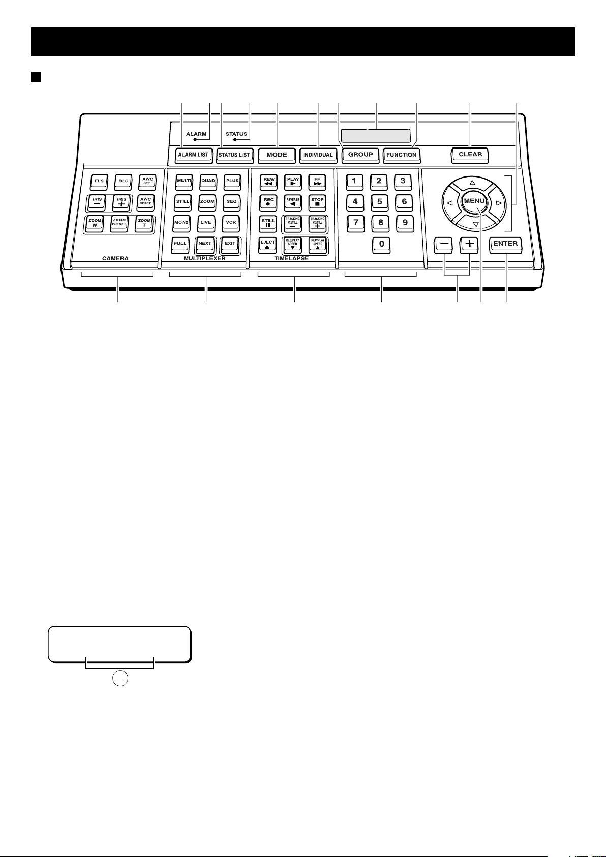
Operation panel
12345 67 8 9 F G
HIJKLMN
1 ALARM LIST button (☞P29)
Press to display the alarm data for each device.
2 ALARM lamp (☞P29)
Lights to notify you if an alarm occurs at a device.
3 STATUS LIST button (☞P30)
Press to display the status data for each device.
4 STATUS lamp (☞P30)
Lights to notify you if the status of a device changes.
5 MODE button
Press to select the device (multiplexer, timelapse VCR, or
camera) to operate.
6 INDIVIDUAL button (☞P15, 17, 18)
Press for separate operation of individual devices.
7 GROUP button (☞P24)
Press to operate a group of devices simultaneously.
8 Menu screen
When the power switch on the rear panel is turned on, the
screen shown below is displayed. A denotes the section
where the date and time are displayed when they are set.
Also, when the operation buttons are pressed, the operating
status and settings are displayed here.
SANYO Controller
--:--:--
A
9 FUNCTION button (☞P17, 20)
Press to operate the various devices by calling up their
commands.
F CLEAR button
Press to clear what you have entered.
G Up, down, left, and right arrow buttons
Press to move the location of the cursor.
H ENTER button
Press to enter and finalize the settings.
I MENU button (☞P7)
Press to bring up the menus. Switches between the menu
display and initial display each time pressed.
J Plus (+) and minus (–) buttons
Press to switch between menus and select settings.
K Numeric keypad (0 to 9)
Press to enter alphanumeric characters and symbols.
L TIME LAPSE command button (☞P18)
Press for timelapse VCR operation.*
M MULTIPLEXER command button (☞P15)
Press for multiplexer operation.*
N CAMERA button (☞P22)
Press for camera operation.*
* In order to allow operation of command buttons L, M and N,
a serial communication port (either a RJ-11 or Push-lock port)
is required.
3
PART NAMES
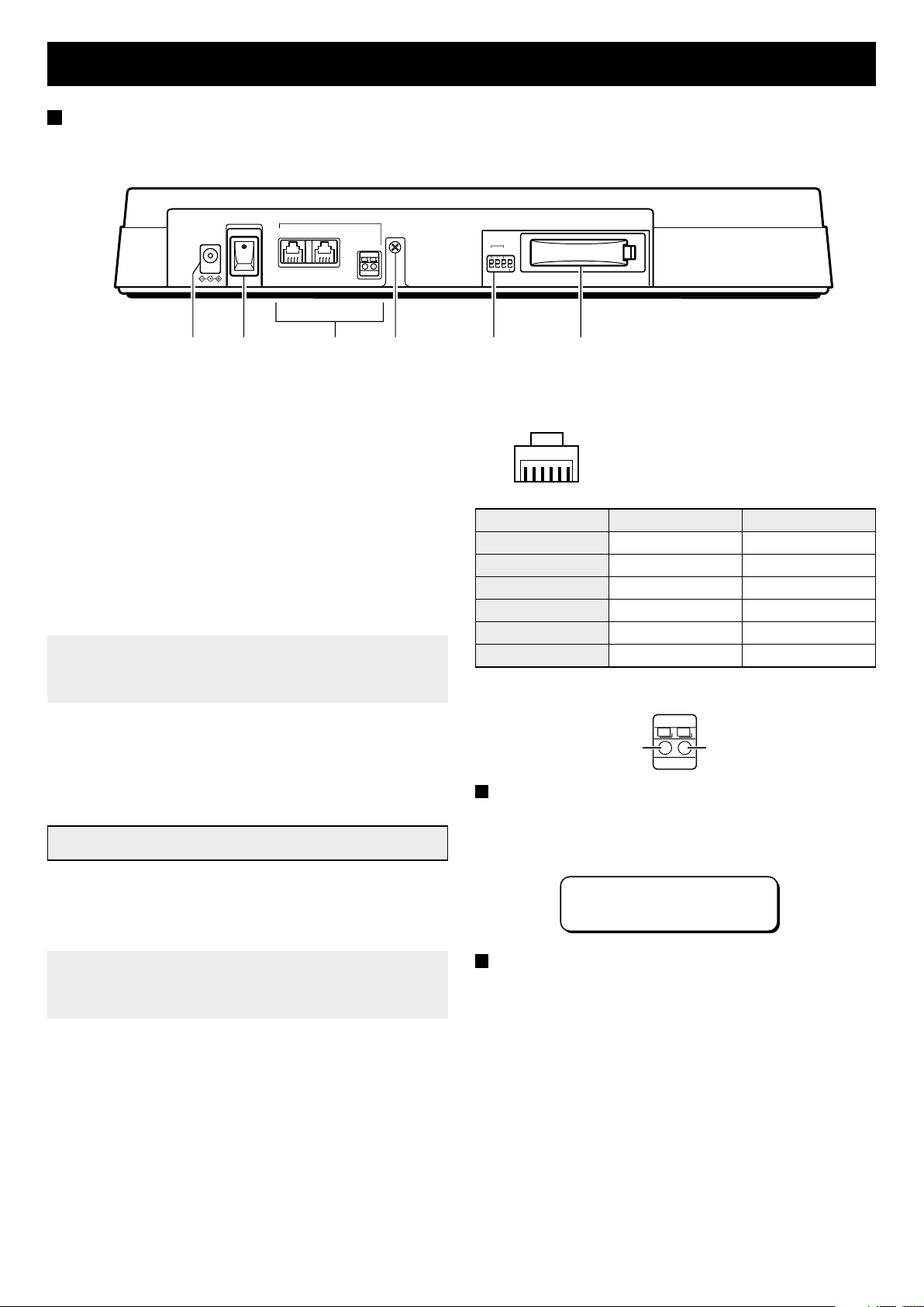
Rear panel
RS485
AAB
12V DC IN
POWER
ON
OFF
12 3 4 5 6
1 Power supply plug (12V DC IN)
Connect the AC adapter supplied with the VSP-7000.
2 POWER switch
Use to turn the VSP-7000 on and off.
3 RS-485 control port
(A) RJ-11 A terminal
Used for connection with a modular cable.
(B) RJ-11 B terminal
Used for connection with a modular cable.
(AB) Push-lock terminal
Used for connection with a twisted-pair cable.
Note:•Do not connect to a phone line.
Only up to two RS-485 control ports can be used.
•
Do not use all of the RS-485 control ports.
•
4 Ground (GND) for twisted-pair cable
GND
B
ADDRESS
123
TERMINATE
1
0
(RJ-11 A and B terminals)
654321
Pin number A terminal signal B terminal signal
1
2
3
4
5
6
Not used Not used
Not used Not used
A signal B signal
B signal A signal
Not used Not used
Not used Not used
(Push-lock terminal)
AB
5 ADDRESS/TERMINATE switch
Used to set the VSP-7000 for addressing or termination.
6 Battery compartment
Backup function
The VSP-7000 is equipped with a lithium battery for backing up
the internal clock of the unit. The battery is charged when power
is supplied to the unit. After 30 hours of charging, the battery is
capable of maintaining the clock operation for up to 30 days.
Note: If power is supplied to the unit for only a short period of
time, the battery may run out of power and cause the
clock to be incorrect.
A signal B signal
Battery life
With the AC adapter unplugged from the wall socket, wait
approximately one hour and then turn on the power and check
the initial screen. If the screen shown below appears, then the
battery has expired. At this point, replace it with a new battery.
SANYO Controller
--:--:--
Battery replacement
Have the battery replacement done at the same sales outlet
where you purchased the VSP-7000. After the new battery is
installed, set the date and time as explained in “Setting the
Date and Time.”
4
CONNECTING THE VSP-7000
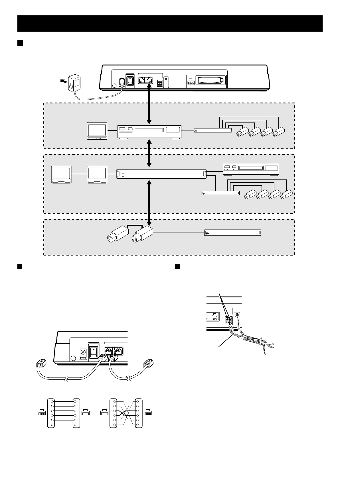
Basic setup
With all the devices turned off, connect all the devices with modular cable using their RS-485 control terminals. There are straight-type
and cross-type modular cables, so be careful mistake them during connecting.
To wall socket
Monitor 1
(sold
separately)
Television monitor
(sold separately)
Monitor 2
(sold
separately)
12V DC IN
POWER
RS485
AAB
ON
OFF
GND
B
ADDRESS
123
TERMINATE
1
0
Modular cable
Timelapse VCR
(sold separately)
Modular cable
Drive unit
(sold separately)
Timelapse VCR (sold separately)
Video camera
(sold separately)
Multiplexer (sold separately)
Modular cable
Drive unit
(sold separately)
Video camera
(sold separately)
Video camera (sold separately)
Connecting using the RJ-11 terminal
Make the connections with a modular cable (either the one
supplied with the VSP-7000 or one sold separately).
When using a straight-type cable (supplied with the
•
VSP-7000)
Connect the A terminals together and the B terminals
together.
When using a cross-type cable (sold separately)
•
Connect the A terminal to B and the B terminal to A.
POWER
12V DC IN
To terminal A To terminal A
ON
OFF
Straight-type cable Cross-type cable
Not used
1
Not used
2
3
4
1616
Not used
5
Not used
6
1
2
3
4
5
6
Straight type
RS485
AB
Not used
1
Not used
2
3
4
1616
5
Not used
6
Not used
1
2
3
4
5
6
Cross type
Drive unit (sold separately)
Connecting using the push-lock terminal
Make the connections with a twisted-pair cable. Connect the A
signals together and the B signals together.
Push in to insert cable
RS485
Twisted-pair cable
GND
ABB
To B signal
To A signal
Ground
5
CONNECTING THE VSP-7000
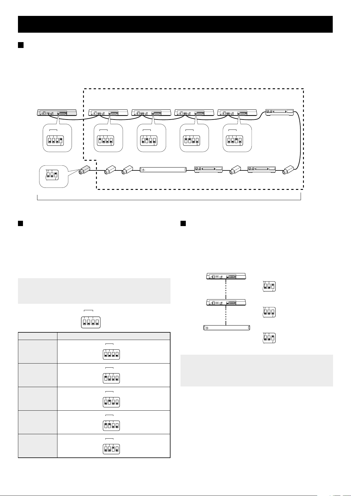
Number of devices that can be connected
The devices are to be connected in series (i.e., daisy-chain connection) with either modular cables or twisted-pair cables. For details
regarding how to set the address and termination for a device, refer to the instruction manual supplied with that device.
Number of VSP-7000s that can be connected together: Max. 5
•
Number of each device (multiplexers, timelapse VCRs, and cameras) that can be connected together: Max. 128
•
Number of devices in system: Max. 256
•
(Termination switch: OFF)
Controller 0 Controller 1 Controller 2
Controller 3 Controller 4
Timelapse 0
ADDRESS
123
1
0
TERMINATE
TERMINATE: 1 (ON)
1
1
0
0
TERMINATE
TERMINATE: 1 (ON)
ADDRESS
123
1
0
TERMINATE
Camera
ADDRESS
123
1
0
TERMINATE
Multiplexer 1
Max. 256 devices total
Setting the address
When connecting multiple VSP-7000s, assign the address
(switches 1 to 3) and termination for each unit on its rear panel.
The address can be set from 1 to 4 for each unit.
If the address for a unit is set to 0, then that unit becomes the
master controller.
Switch 1 is the least significant bit (LSB) and switch 3 the
•
most significant bit (MSB) (Down: 0, UP: 1)
Note: If an address other than one of those shown in the table
below is set, then “ADDRESS ERROR” will appear
flashing in the menu screen.
ADDRESS
123
Unit address Position of ADDRESS/TERMINATE switches
0
1
1
0
123
123
1
0
1
0
ADDRESS
123
1
0
TERMINATE
Timelapse
VCR
(Termination switch: OFF)
ADDRESS
123
TERMINATE
Camera
2
1
0
Timelapse
VCR 2
Camera
1
Setting the termination
The devices located at each end of the daisy-chain must be set
with their termination turned on.
To turn on the termination, set the termination switch of the
•
ADDRESS/TERMINATE switch to 1 (ON).
For all the devices other the ones located at the ends, set the
•
termination switch to 0 (OFF).
Termination switch
at 1 (ON)
Termination switch
at 0 (OFF)
Termination switch
at 1 (ON)
Note: If the termination is not properly set, data will be
reflected at the ends of the daisy-chain and affect other
data, resulting in incorrect data being sent to the various
devices.
1
0
TERMINATE
1
0
TERMINATE
1
0
TERMINATE
2
3
4
123
123
1
23
1
0
1
0
1
0
6
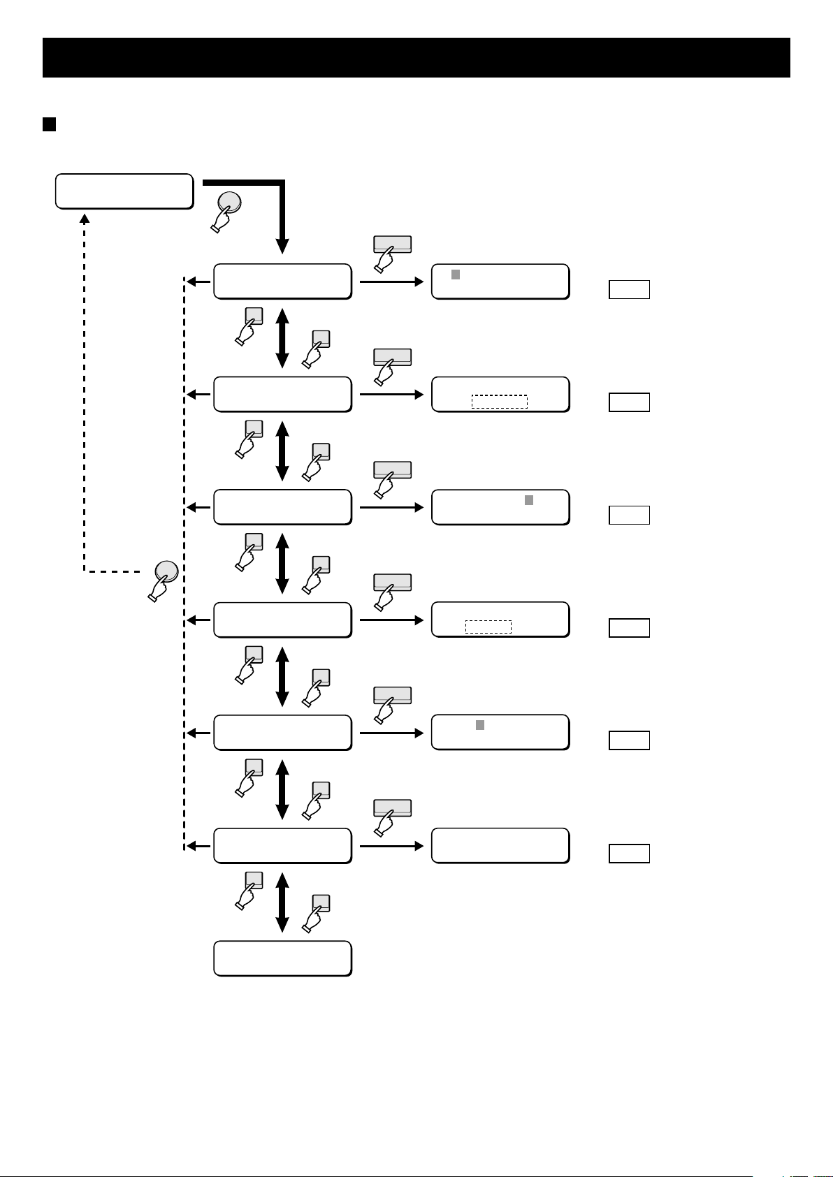
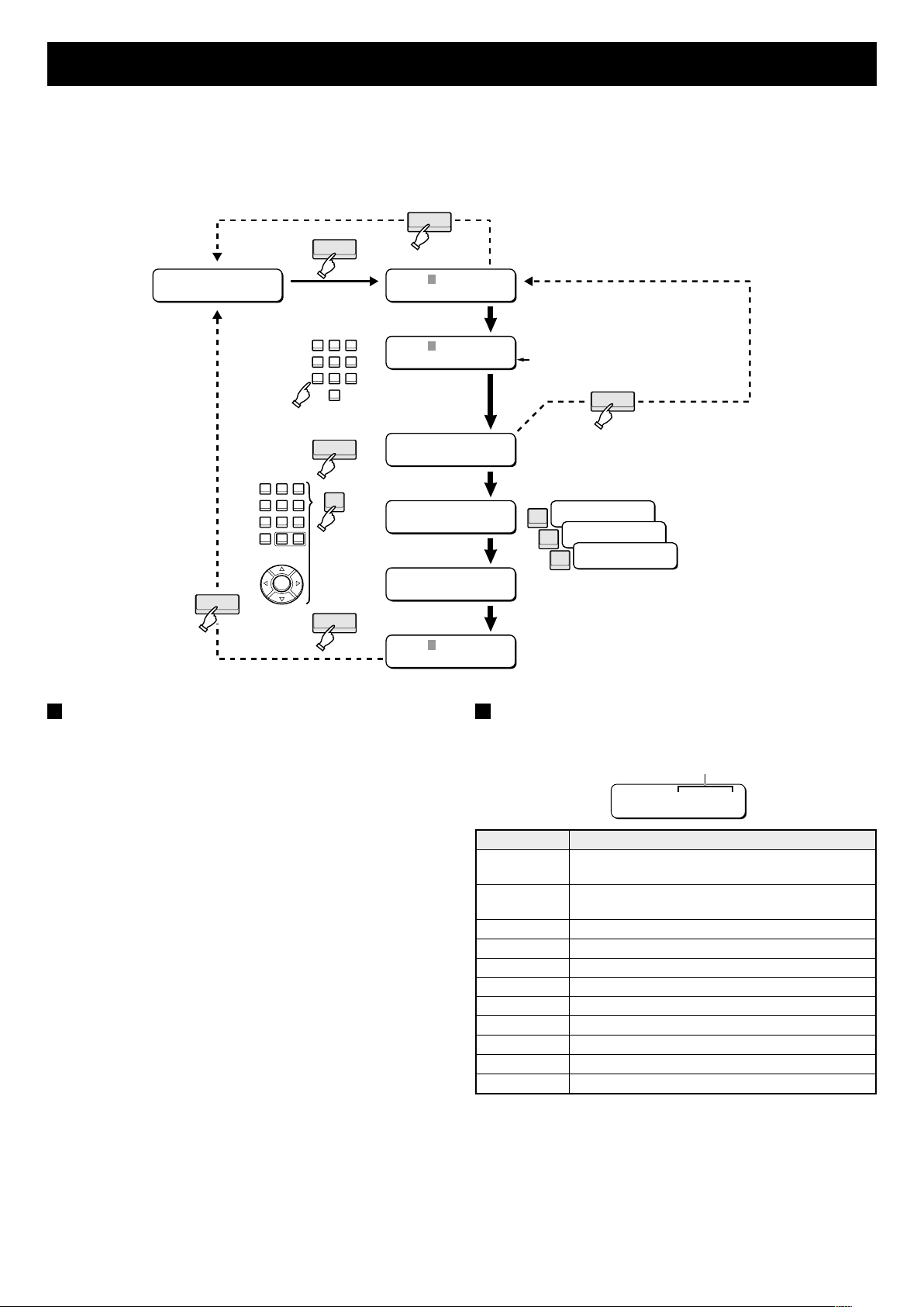
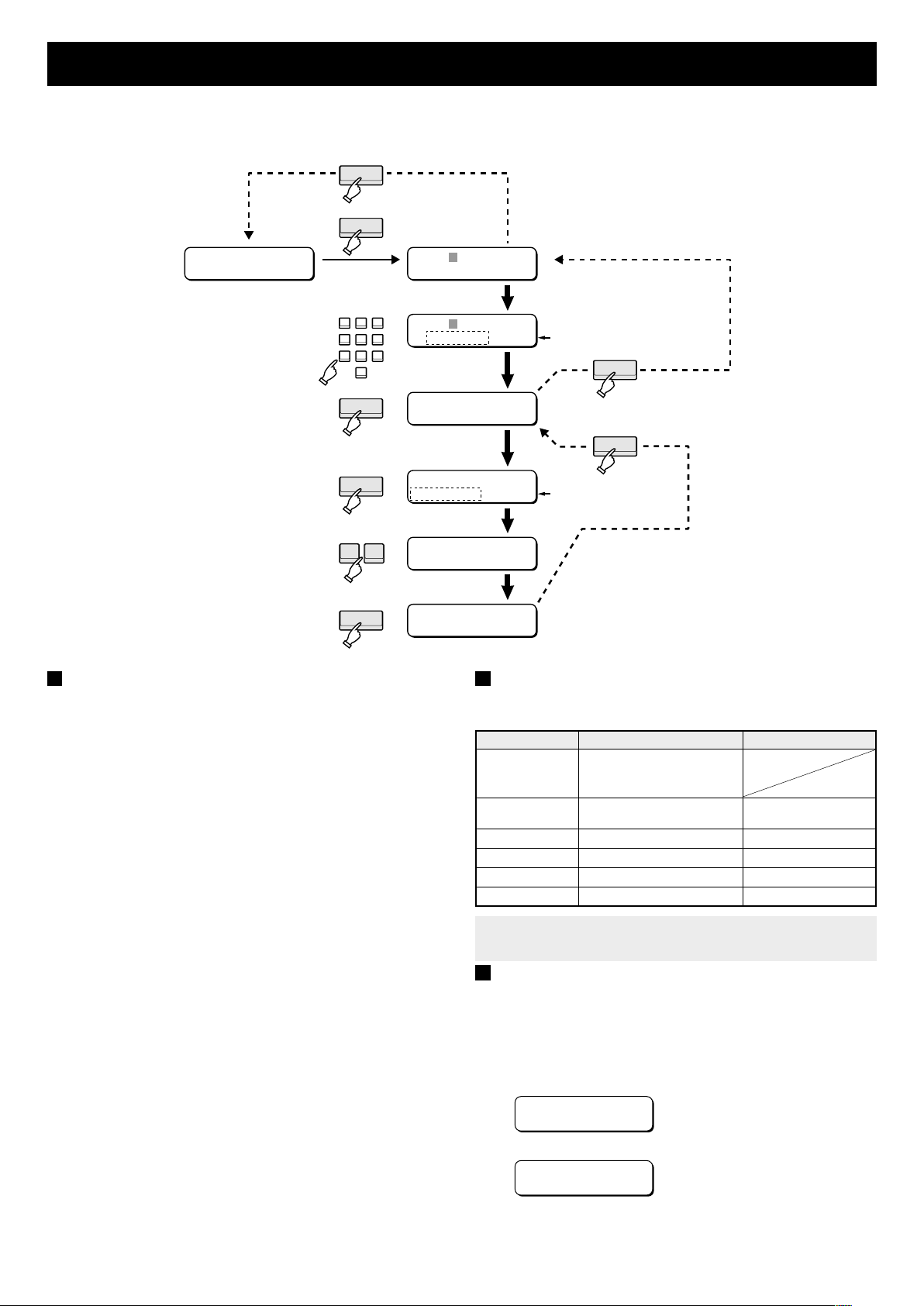
MENU SETTINGS
. The settings are performed at the menu screen area.
Displaying the menu screen
Press the MENU button and then press either the + or – buttons to switch between the different menu screens.
Initial display
SANYO Controller
--:--:--
MENU
MENU
CLOCK SET
–
+
SUMMER TIME SET
<DAY LIGHT TIME>
–
+
SECURITY LOCK
–
+
BAUD RATE SET
–
+
TITLE SET
–
+
GROUP CHECK
–
+
CLOCK SET
ENTER
ENTER
ENTER
ENTER
ENTER
ENTER
Y:--/M:--/D:--
--:--:00
SUMMER TIME
NO USE
CODE=????
Setting the Date and Time
☞
Setting Daylight-saving Time
☞
Setting the Security Locks
☞
BAUD RATE SET
19200 bps
MX:
---
Setting the Communication Speed
☞
Setting the Title
☞
GROUP CHECK ?
OK:ENTER NO:CLR
Checking the Group Settings
☞
P8
P9
P10
P12
P13
P14
T
u
r
n
o
n
t
h
e
V
S
P
7
0
0
0
w
i
t
h
t
h
e
p
o
w
e
r
s
w
i
t
c
h
o
n
t
h
e
r
e
a
r
p
a
n
e
l
,
a
n
d
s
e
t
t
h
e
d
a
t
e
a
n
d
t
i
m
e
7
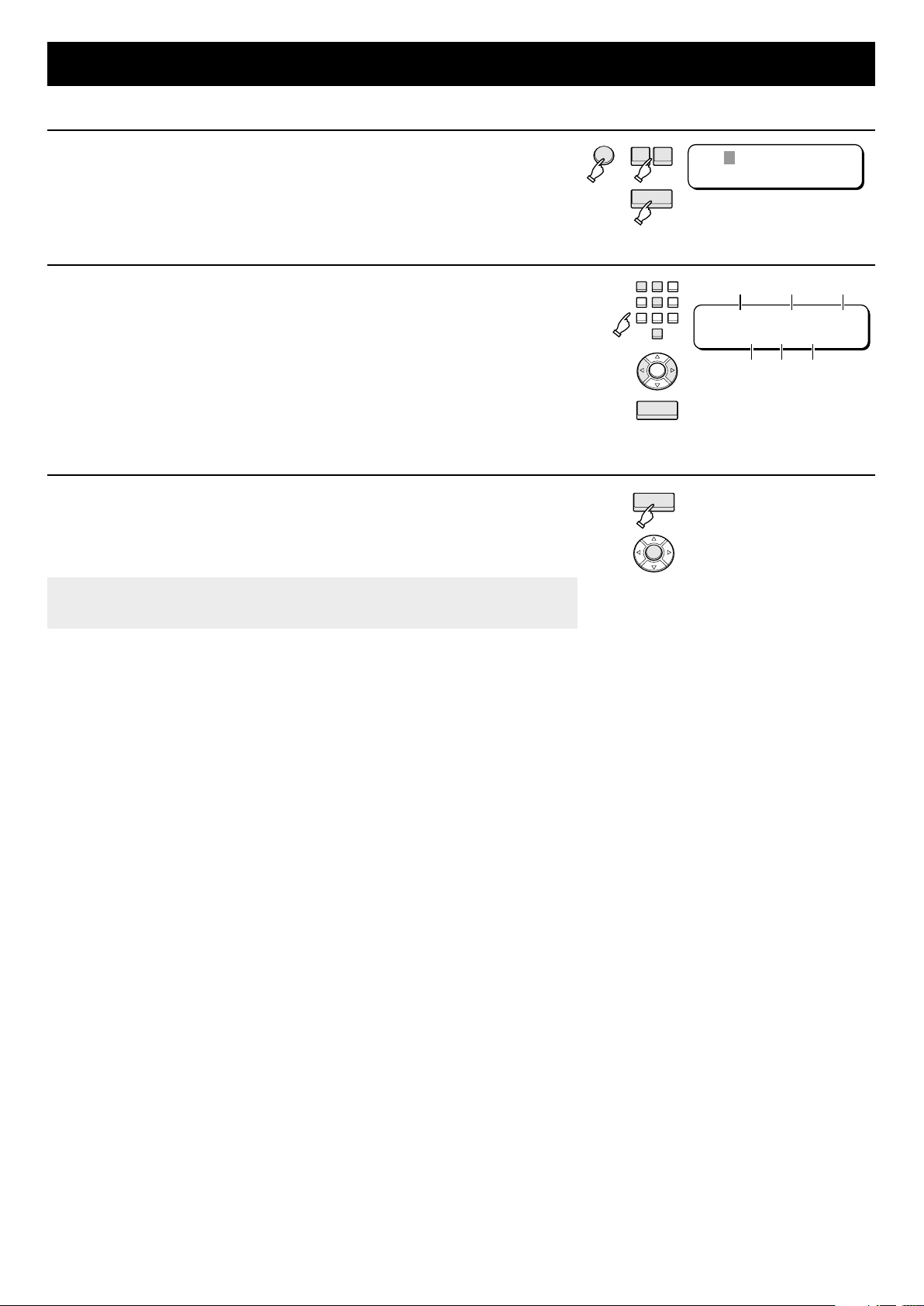
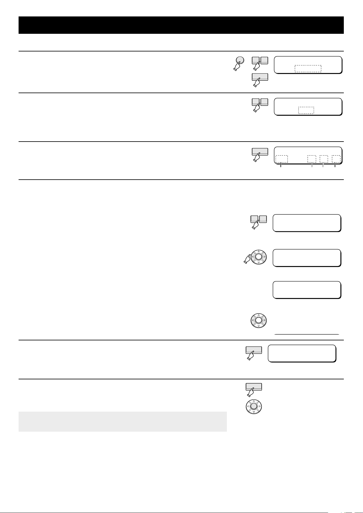
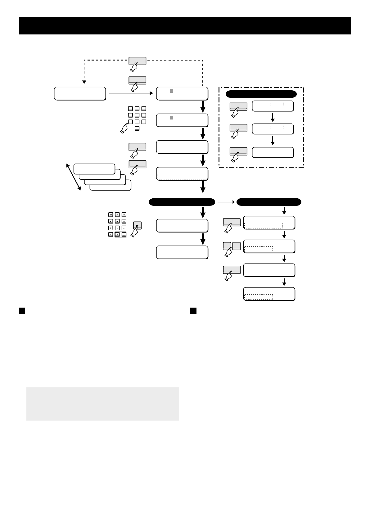
SETTING THE DATA AND TIME
Example: Setting to the date May 10, 2000 and the time 9:00:00.
Press the MENU button.
1
Then press the + (or –) button until “CLOCK SET” is displayed and
press the ENTER button.
The date and time setting screen appears.
•
Set the year, month, day, hour, minute, and second with the
2
numeric keypad.
For the year 2000, press [0] [0]. The cursor will move to the month.
•
For single digit numbers, first enter a zero.
•
Ex.: To enter the month of May, press [0] [5].
The clock is a 24-hour clock.
•
Ex.: To enter 9:00 p.m. (21:00), press [2] [1].
For mistakes: Either press the left or right arrow buttons to move the cursor, or
press the CLEAR button. Then recheck and enter correct setting.
Press the ENTER button.
3
The settings are stored and the “CLOCK SET” screen reappears.
•
Press the MENU button to return to the initial screen.
Note: To abort the setting, press the MENU button. When pressed, the job will be
cancelled and you will return to the initial screen.
MENU
+-
ENTER
123
456
789
0
MENU
CLEAR
ENTER
MENU
Y:--/M:--/D:--
--:--:00
MonthYear Day
Y:00/M:05/D:10
21:20:00
Hour Minute Second
8
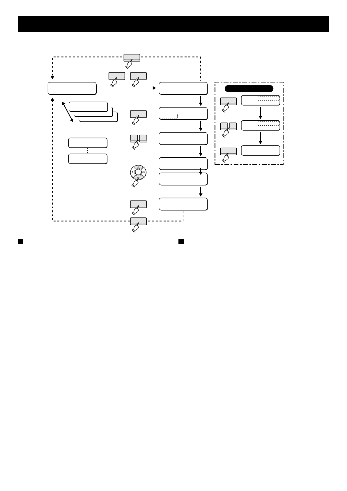
SETTING DAYLIGHT-SAVING TIME
Set the daylight-saving time (summer time) so that clock will automatically change at the start and end of daylight-saving time.
Press the MENU button.
1
Then press the + (or –) button until “SUMMER TIME SET” is
displayed and press the ENTER button.
Set whether or not you want the time automatically adjusted for
•
daylight-saving time.
Press the + (or –) button to change the display to “USE” for
2
automatic adjustment of the clock for daylight-saving time.
Switches between “NO USE” and “USE” each time pressed (there is no “auto”
•
setting).
If you press the ENTER button while “NO USE” is displayed, you will return to
•
the “SUMMER TIME SET” screen.
Press the ENTER button.
3
The screen for setting the daylight-saving time start appears.
•
MENU
ENTER
ENTER
+-
SUMMER TIME
NO USE
(Flashing)
+-
SUMMER TIME
USE
ON: WEEK MO TIME
1ST-SUN 04 02:00
Month MinuteHourWeek
If it is necessary to change the current day-light saving time setting, follow the procedure given below.
Example: Daylight-saving time start: 3:00 a.m. on second Saturday of March
Daylight-saving time end: 2:00 a.m. on last Sunday of October
1 Press the + (or –) button to select the field for setting the start week (default:
1ST) and then press the right arrow to select the week.
The display will change from “1ST” → “2ND” → “3RD” → “4TH” → “LST” →
•
“1ST” each time the + (or –) button is pressed.
2 Press the + (or –) button to select the field for setting the start day (default:
SUN) and then press the right arrow to select the day.
The display will change from “SUN” → “MON” → “TUE” → “WED” → “THU”
•
→ “FRI” → “SAT” → “SUN” each time the + (or –) button is pressed.
3 As in 2, set the start month (default: 04) and the start time (default: 02).
The month will change from “01” → “02” → “03” ... “11” → “12” → “01” each
•
time pressed.
The hour will change from “01” → “02” → “03” ... “21” → “22” → “01” each
•
time pressed.
The minute will change from “00” → “01” → “02” ... “58” → “59” → “00” each
•
time pressed.
For mistakes: Either press the left or right arrow buttons to move the cursor,
and then recheck and select correct setting.
+-
ON: WEEK MO TIME
2ND-SUN 04 02:00
ON: WEEK MO TIME
MENU
2ND-SAT 04 02:00
ON: WEEK MO TIME
2ND-SAT 03 03:00
MENU
Press the ENTER button.
4
The screen for setting the daylight-saving time end appears.
•
If the daylight-saving time differs from the default setting displayed, set it using
•
the same procedure given in step 3 “Example”.
Press the ENTER button.
5
The settings are stored and the “SUMMER TIME SET” screen reappears.
•
Press the MENU button to return to the initial screen.
Note: To abort the setting, press the MENU button. When pressed, the job will be
cancelled and you will return to the initial screen.
9
ENTER
ENTER
MENU
OFF:WEEK MO TIME
LST-SUN 10 02:00
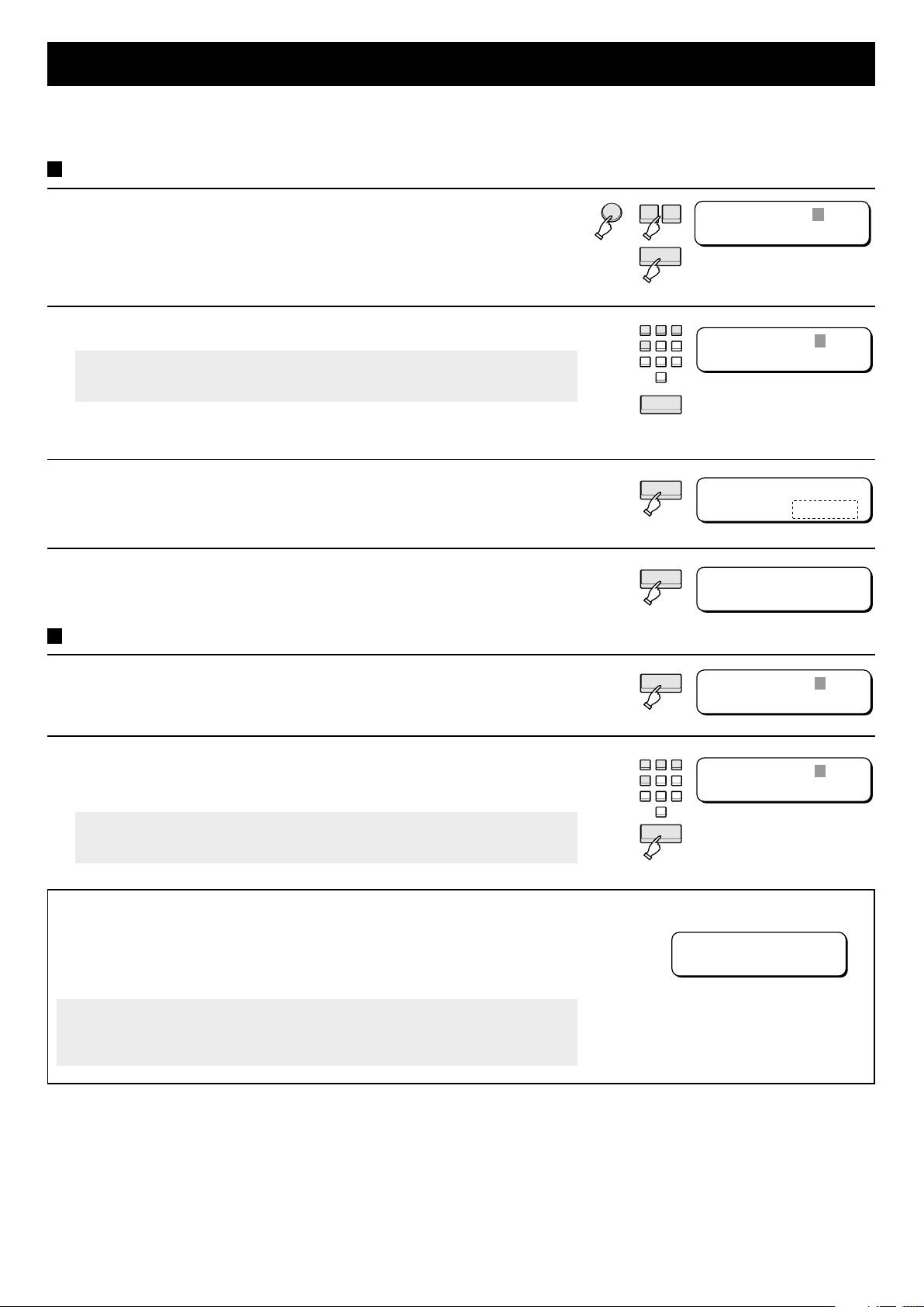
SETTING THE SECURITY LOCKS
To prevent unwarranted use of the VSP-7000 while it is operating, the unit or the entire system can be set to a security lock by
entering a secret code. There are two types of security locks: a simple lock that does not depend on the time, and a timer lock that
only activates during a set time period. Also, by locking the master controller (address 0), the entire system becomes locked.
Simple locks
Press the MENU button.
1
Then press the + (or –) button until “SECURITY LOCK” is displayed
and press the ENTER button.
The secret code entry screen appears.
•
Enter the secret code (e.g., 1234) with the numeric keypad.
2
Note: The secret code will be required to deactivate the lock, so be sure to
write it down so it is not forgotten.
For mistakes Press the CLEAR button and reenter the secret code.
If the secret code is lost or forgotten, contact your nearest Sanyo dealer or
representative.
Press the ENTER button.
3
The “NO USE” (to use the simple lock function) appears flashing.
•
Press the ENTER button again.
4
The simple lock is set and the initial screen appears.
•
Deactivating the lock
MENU
+-
ENTER
123
456
789
0
CLEAR
ENTER
ENTER
CODE=????
CODE=1234
CODE=1234
TIMER:NO USE
SANYO Controller
21:20:00
Press any button on the operation panel.
1
The secret code entry screen appears.
•
Enter the secret code with the numeric keypad and press the
2
ENTER button.
The lock is deactivated.
•
Note: To reset the security lock or timer lock, return to the “SECURITY LOCK”
screen and reentes the secret code.
Using the security lock for the entire system
If the security lock is activated at the master controller (address 0), then the whole
system becomes locked. If the whole system is locked, then “LOCKED BY
MASTER” will be displayed in the menu screen of the all the controllers except
address 0.
Note: Do not set two or more controllers to the address 0. If there are more than
one controller with the address 0, the controller that was first set will
become the master controller.
CODE=????
LOCKED
123
456
789
ENTER
CODE=1234
LOCKED
0
LOCKED
BY MASTER
10

SETTING THE SECURITY LOCKS
TIMER LOCK
Press the MENU button.
1
Then press the + (or –) button until “SECURITY LOCK” is displayed
and press the ENTER button.
The secret code entry screen appears.
•
Enter the secret code (e.g., 1234) with the numeric keypad.
2
Note: The secret code will be required to deactivate the lock, so be sure to
write it down so it is not forgotten.
For mistakes: Press the CLEAR button and reenter the secret code.
If the secret code is lost or forgotten, contact your nearest Sanyo dealer or
representative.
Press the ENTER button.
3
The “NO USE” (to use the simple lock function) appears flashing.
•
Press the + (or –) button to change the display to “USE” and then
4
press the ENTER button.
Enables the timer lock function.
•
MENU
+-
ENTER
123
456
789
0
ENTER
+-
ENTER
CODE=????
CODE=1234
CODE=1234
TIMER:NO USE
CODE=1234
TIMER:USE
CODE=1234
ON00:00 OFF00:00
Use the numeric keypad to enter the lock start and end times.
5
Example: Setting the lock to activate at 3:00 p.m. (15:00) and deactivate at
5:30 p.m. (17:30).
1 Using the numeric keys, press [1, 5, 0, 0] for the start time (“ON”).
2 Using the numeric keys, press [1, 7, 3, 0] for the end time (“OFF”).
For mistakes: Either press the left or right error buttons to move the cursor, and
then reselect the desired setting.
Press the ENTER button.
6
The initial screen reappears and the timer lock will activate at the set time.
•
A: Deactivating the timer lock while it is locked
1 Press any button on the operation panel.
The secret code entry screen appears.
•
CODE=????
TIMER LOCKED
B: Deactivating the timer lock while it is unlocked
1 Press the MENU button. Then press the + (or –)
button to select “SECURITY LOCK” and press the
ENTER button.
2 Enter the secret code with the numeric keypad
and press the ENTER button.
The timer lock is deactivated and the initial screen
•
reappears.
Note: The timer lock setting will remain active.
2 Enter the secret code with the numeric keypad
and press the ENTER button.
123
456
789
ENTER
The secret code entry screen appears.
•
MENU
•
CODE=????
TIMER LOCKED
The timer lock is deactivated and the initial screen
reappears.
CODE=1234
ON15:00 OFF17:30
0
SANYO Controller
21:20:00
Note: The timer lock setting will remain active.
11

SETTING THE COMMUNICATION SPEED
Set the communication speed (baud rate) at which data is transferred. The baud rate set here should match the baud rate set for
devices that this unit will operate.
Press the MENU button.
1
Then press the + (or –) button until “BAUD RATE SET” is displayed
and press the ENTER button.
The baud rate setting screen appears.
•
Press the + (or –) button to select the desired communication speed
2
(baud rate).
The display will change from “19200” → “2400” → “4800” → “9600” → “19200”
•
(units: bps) each time pressed.
Press the ENTER button.
3
The “BAUD RATE SET” screen reappears.
•
Press the MENU button to return to the initial screen.
MENU
ENTER
ENTER
+-
BAUD RATE SET
19200 bps
(Flashing)
+-
12

SETTING THE TITLE
Set a title (i.e., name) for each device on the system.
Press the MENU button.
1
Then press the + (or –) button until “TITLE SET” is displayed and
press the ENTER button.
The address entry screen appears.
•
Press the MODE button and select the device (VR) that you will give
2
a title.
The display will change from “MX” (multiplexer) → “VR” (timelapse VCR) → “CM”
(camera) → “MX” each time pressed.
Example: Use the numeric keypad to the address of the device.
3
For address 13, press [1][3].
•
Note: Addresses can be set up to the number 127. If you enter an address of
128 or higher, an error will occur.
Press the ENTER button.
4
The title entry screen appears.
•
Example: Enter the title “SET1” for the device.
5
By pressing repeatedly pressing a numeric key, you can scroll through the
•
various alphanumeric characters and symbols.
1 Press [7] five times (for “S”), and press the right arrow button.
2 Press [3] three times (for “E”), and press the right arrow button.
3 Press [8] two times (for “T”), and press the right arrow button.
4 Press [1] once (for “1”), and press the right arrow button.
VR:
Error
---
MENU
+-
ENTER
MODE
123
456
789
0
ENTER
123
456
789
0
MENU
MX:
---
VR:
---
VR:-1 3
VR:013
- -----------
VR:013
SET1
--------
Numeric key Title display Numeric key Title display
1
2
ABC
3
DEF
4
GHI
5
JKL
For mistakes: Either press the left or right error buttons to move the cursor, and
Press the ENTER button.
6
The address entry screen for the next address appears.
•
Press the MENU button to return to the initial screen.
To confirm the title, refer to pages: P15, P18, P22
1 3 __ 3 1 6 3 M 3 N 3 O 3 __ 3 6
2 3 A 3 B 3 C 3 __ 3 2 7 3 P 3 Q 3 R 3 S 3 __ 3 7
3 3 D 3 E 3 F 3 __ 3 3 8 3 T 3 U 3 V 3 __ 3 8
4 3 G 3 H 3 I 3 __ 3 4 9 3 W 3 X 3 Y 3 Z 3 __ 3 9
5 3 J 3 K 3 L 3 __ 3 5 0 3 - 3 / 3 : 3 __ 3 0
enter the correct character.
6
MNO
7
PQRS
8
TUV
9
WXYZ
0
– / :
ENTER
MX:
---
13

CHECKING THE GROUP SETTINGS
When you set the groups, each device stores the information regarding which group they belong to in their memory. When you
perform a group check, The group information is read from each device connected via the RS-485 interface and the group settings are
renewed. For more information regarding the group settings, refer to GROUP SETTING on page 24.
Press the MENU button.
1
Then press the + (or –) button until “GROUP CHECK” is displayed
and press the ENTER button.
The group check screen appears.
•
Note: Press the CLEAR button to return to the “GROUP CHECK” screen.
Press the ENTER button.
2
Performs the group check. During the check, the cursor will move to the right.
•
When the group check is completed, the data gathered is stored in memory
•
and the “GROUP CHECK” screen reappears.
Press the MENU button to return to the initial screen.
Note:
Always perform the group check if group settings were changed at another controller.
•
If a device belonging to group has its address changed, is removed from the system, or is changed to another group, then be
•
sure to perform the group check to update the group settings.
Do not operate a controller while one controller is performing a group check.
•
MENU
ENTER
CLEAR
ENTER
+-
GROUP CHECK ?
OK:ENTER NO:CLR
GROUP CHECK
14
MULTIPLEXER OPERATION
The VSP-7000 enables two methods of multiplexer operation. One is performing direct operation using the command buttons on the
VSP-7000 [A] and the other is by using the call-up commands to bring up commands to the menu screen [B].
[A] Operation using the command buttons
Use the procedure outlined below to operate the multiplexers.
CLEAR
SANYO Controller
15:30:30
QUAD PLUS
MULTI
SEQZOOM
STILL
LIVE
VCR
MON2
NEXT EXIT
FULL
MULTIPLEXER
MENU
CLEAR
INDIVIDUAL
123
456
789
0
ENTER
SEQ
CLEAR
1 Device display
MX:
---
2 Address entry
MX:--1
2NDFLOOR
3 Address check
MX:001 L:MULTI
4 Operation
execution
MX:001 <SEQ>
MX:001
MX:
---
Device title (☞ P13)
CLEAR
☞
Refer to “Checking the Address”
(Example)
MX:001 <QUAD>
QUAD
MX:001 <MULTI>
MULTI
MX:001 <LIVE>
LIVE
Operating procedure
1. Press the INDIVIDUAL button.
The device display screen (default: MX) appears.
•
2. Enter the address with the numeric keypad.
3. Press the ENTER button to check the address status.
The operating status of the multiplexer appears in the
•
menu screen. (Refer to Checking the address.)
4. Press the desired command buttons located in the
MULTIPLEXER section of your VSP-7000.
For an explanation of the multiplexer command buttons,
•
refer to the Command button operation list on page 16.
Checking the address
When the address is checked in step 3, the operating status of
the multiplexer appears in the menu screen.
MX:001 L:MULTI
Status Operating condition
L: MULTI Live picture mode, multi-screen
(9-screen/16-screen)
V: MULTI Video playback mode, multi-screen
(9-screen/16-screen)
L: QUAD Live picture mode, quad-screen
L: QUAD: S Live picture mode, quad-screen, sequential display
L: PLUS 16 Live picture mode, plus screen, 16-screen
L: PLUS: S Live picture mode, plus screen, sequential display
L: FULL: S Live picture mode, full screen sequential display
L: FULL: 16 Live picture mode, 16-channel full screen
M2SET: 16 16-screen for monitor 2
M2SET: S Sequential display for monitor 2
MENU Menu screen
If a “V” is where the “L” is, then it is in the video playback mode.
•
Operating status
15
MULTIPLEXER OPERATION
Command button operation list
The ☞ in the table tells you the corresponding section below for reference.
VSP-7000 command button Operation Menu screen
MULTI Splits monitor 1 into multiple screens (16-screen ↔ 9-screen) MX:001 <MULTI>
QUAD Splits monitor 1 into four screens MX:001 <QUAD>
PLUS
STILL Stops screen of monitor 1 MX:001 <STILL>
ZOOM Zooms in on monitor 1 (screen 1) MX:001 <ZOOM>
SEQ Sequential display for monitor 1 screen MX:001 <SEQ>
MON2
LIVE Sets live video mode MX:001 <LIVE>
VCR Sets video playback mode (☞E) MX:001 <VCR>
FULL Sets screen 1 to specified channel (☞F) MX:001 <CH-->
NEXT Switches from menu screen to submenu MX:001 <NEXT>
EXIT Exits menu screen MX:001 <EXIT>
MENU Brings up menu screen, or selects menu screen MX:001 <MENU>
J, q, s, t Moves cursor (left, right, up, and down) MX:001 <LEFT>
–, + Selects menu MX:001 <+>
Sets monitor 1 to plus screen MX:001 <PLUS>
•
Switches channel of monitor 1 plus screen (☞A)
•
Set sequential mode for monitor 1 plus screen (☞B)
•
Sets screen 1 to specified channel of monitor 2 (☞C) MX:001 <MON2>
•
Sequential display for monitor 2 screen (☞D)
•
MX:001 <RIGHT>
MX:001 <UP>
MX:001 <DOWN>
MX:001 <->
Operations
A: Switches the channel of the monitor
1 plus screen
1. Press the PLUS button.
2. Press the FULL button.
3. Specify the channel with the numeric
keypad.
Ex.: 4 → [4], 16 → [1] [6]
4. Press the ENTER button.
B: Automatically changes the monitor
1 plus screen
Press the PLUS button.
1.
2. Press the SEQ button.
C: Sets screen 1 to the specified
channel of monitor 2
1. Press the MON2 button.
2. Press the FULL button.
3. Specify the channel with the numeric
keypad.
4. Press the ENTER button.
5. Press the MON2 button again to
complete the setting.
D: Automatically switches the screen
of monitor 2
1. Press the MON2 button.
2. Press the SEQ button.
3. Press the MON2 button again to
complete the setting.
E: Enters the video playback mode
Playback the video.
1.
2. Press the VCR button.
F: Sets screen 1 to the specified
channel
Press the FULL button.
1.
2. Specify the channel with the numeric
keypad.
Ex.: 4 → [4]
MX:001 <CH
3. Press the ENTER button.
MX:001 <CH04>
- -
>
16
MULTIPLEXER OPERATION
[B] Operation using the call-up commands
Use the procedure outlined below to operate the multiplexers.
CLEAR
INDIVIDUAL
1 Device display
SANYO Controller
15:30:30
123
456
789
0
ENTER
FUNCTION
MX:
---
2 Address entry
MX:--1
2NDFLOOR
3 Address check
MX:001 L:MULTI
4 Call-up command
MX:001
POWER OFF
Device title (☞ P13)
CLEAR
CLEAR
Call-up command
5 Command selection
– +
6 Operation execution
ENTER
Operating procedure
1. Press the INDIVIDUAL button.
The device display screen (default: MX) appears.
•
2. Enter the address with the numeric keypad.
3. Press the ENTER button to check the address status.
The operating status of the multiplexer appears in the
•
menu screen.
4. Press the FUNCTION button to bring up the commands.
The command name is displayed flashing.
•
5. Press the – (or +) button to select the desired command.
For an explanation of the multiplexer call-up commands,
•
refer to the Call-up command operation list
6. Press the ENTER button to execute the command.
MX:001
POWER ON
MX:001 PW.ON
Call-up command operation list
The ☞ in the table tells you the corresponding section below for
reference.
Call-up command Operation Menu screen
CLOCK ADJUST Sets the minutes and
MENU RESET Returns the menu screen
POWER OFF Turns off multiplexer
POWER ON Turns on multiplexer
S.LOCK OFF Deactivates the security lock
S.LOCK ON Activates the security lock
Note: If the connected device does not have command
Operations
seconds of the clock to 00
(☞A)
settings to the initial values
MX:001 MENU RST
MX:001 PW.OFF
MX:001 PW.ON
MX:001 S.L.OFF
MX:001 S.L.ON
functions, then “Error” will appear in the menu screen.
A: Sets the minutes and seconds of the clock to 00
Ex.: Set clock to 14:00
Works over the range from 13:30:00 to 14:29:59.
1. Press the + (or –) button to select “CLOCK ADJUST”.
2. Press the ENTER button.
MX:001 CLK ADJ.
PRESS: [ENTER]
3. Press the ENTER button again.
MX:001 CLK ADJ.
17

TIMELAPSE VCR OPERATION
The VSP-7000 enables two methods of timelapse VCR operation. One is performing direct operation using the command buttons on
the VSP-7000 [A] and the other is by using the call-up commands to bring up commands to the menu screen [B].
[A] Operation using the command buttons
Use the procedure outlined below to operate the timelapse VCRs.
CLEAR
SANYO Controller
15:30:30
REW
PLAY FF
REC
STOP
REVERSE
TRACKING
TRACKING
STILL
V.STILL
V.STILL
REC/PLAY
REC/PLAY
EJECT
SPEED
SPEED
TIMELAPSE
CLEAR
MENU
INDIVIDUAL
MODE
3
12
456
789
0
ENTER
PLAY
CLEAR
1 Device display
MX:
---
2
Device selection
VR:
---
3 Address entry
VR:-2 3
VIDEO23
4 Address check
VR:023 STOP 24H
5 Operation
execution
VR:023 <PLAY>
VR:023 PLAY
VR:
---
MX:
---
VR:
---
CM:
---
Device title (☞ P13)
CLEAR
☞
Refer to “Checking the Address”
(Example)
VR:023 <FF>
FF
VR:023 <REW>
REW
VR:023 <STOP>
STOP
Multiplexer
Timelapse VCR
Camera
Operating procedure
1. Press the INDIVIDUAL button.
The device display screen (default: MX) appears.
•
2. Press the MODE button to change the displayed device to
“VR”.
3. Enter the address with the numeric keypad.
4. Press the ENTER button to check the address.
The operating status of the timelapse VCR appears in the
•
menu screen. (Refer to Checking the address.)
5. Press the desired command buttons located in the
TIMELAPSE section of your VSP-7000.
For an explanation of the timelapse VCR command
•
buttons, refer to the Command button operation list on
page 19.
To abort the operation, press the STOP button of the
timelapse VCR.
Checking the address
When the address is checked in step 4, the operating status and
recording/playback speeds are displayed in the menu screen. If
the operating status changes, only the status that changes is
displayed.
Operating status
Recording/playback speed
VR:001 STOP 24H
Status Description Status Description Status Description
C.OUT OF Eject
cassette
during
standby
COUT/
C.OUT ON
Eject
cassette
CUE Cueing REC Recording STOP Stopped
F.ADV Forward
advancing
FF Fast-
forwarding
PAU/
PAUSE
Recording
paused
PLAY Playing
R.F.ADV Reverse
REW Rewinding TSTB/ TM
RPLY/
RVS.PLAY
RVW Reviewing
Operating status that changed
VR:001 C.OUT ON
back
advancing
Reverse
playing
back
STBY Standby
STL/
Pausing
STILL
Timer
STBY
recording
standby
18

TIMELAPSE VCR OPERATION
Command button operation list
The ☞ in the table tells you the corresponding section below for reference.
Command button Operation Menu screen
REW f
PLAY c
FF e
REC a Performs recording (☞A) VR:001 REC OK?
REVERSE d Plays back tape in reverse VR:001 <R.PLAY>
STOP b Stops tape VR:001 <STOP>
STILL h
TRACKING V.STILL –
TRACKING V.STILL +
EJECT i Ejects tape (☞F) VR:001 EJECT OK?
REC/PLAY SPEED l Decreases menu screen settings and recording/playback speed VR:001 <SPD DN>
REC/PLAY SPEED j Increases menu screen settings and recording/playback speed VR:001 <SPD UP>
MENU Brings up the menu screen, or selects the menu screen VR:001 <MENU>
J Moves cursor to left in menu screen (may not be applicable with
q Moves cursor to right in menu screen, also moves date/time screen
t Moves the cursor downward in the menu screen (may not be applicable
Rewinds the tape VR:001 <REW>
•
Rewinds the tape during playback VR:001 <RVW>
•
Reverse advances by frame VR:001 <REW>
•
Plays back the tape VR:001 <PLAY>
•
Enables checking of recording while recording
•
Fast-forwards the tape VR:001 <FF>
•
Fast-forwards the tape during playback VR:001 <CUE>
•
Advances by frame VR:001 <FF>
•
OK:ENTER NO:CLR
Stops image during playback VR:001 <STILL>
•
Stops image during recording
•
Adjusts tracking and reduces noise (☞B) VR:001 <TR UP>
•
Adjust vertical synchronicity and reduces vertical wavering during
•
stills (☞C)
Returns tracking to initial value (☞D)
•
Returns vertical synchronicity to initial value (☞E)
•
some devices)
to right
with some devices), also moves display of date and time downward.
VR:001 <TR DWN>
OK:ENTER NO:CLR
VR:001 <LEFT>
VR:001 <RIGHT>
VR:001 <DOWN>
Operations
A: Performs recording
Press REC button.
1.
To prevent mistaken operations at the
controller, the confirmation screen
shown below appears.
VR:001 REC OK?
OK:ENTER NO:CLR
2. Press ENTER button.
VR:001 REC
B: Adjusts tracking and reduces noise
1.
During playback, press the TRACKING
V.STILL + button a number of times.
2. If the video noise persists, adjust with
the TRACKING V.STILL – button.
C: Adjust vertical synchronicity and
reduces vertical wavering during
stills
1.
While paused, press the TRACKING
V.STILL + button a number of times.
2. If the vertical wavering persists, adjust
with the TRACKING V.STILL – button.
D: Returns tracking to the center
position (“CTR”)
Press the TRACKING V.STILL + button
while holding down the TRACKING
V.STILL – button.
VR:001 <TR CTR>
19
E: Returns vertical synchronicity to
the center position (“CTR”)
Press the TRACKING V.STILL + button
while holding down the TRACKING
V.STILL – button.
VR:001 <TR CTR>
F: Ejects tape
Press the EJECT button.
1.
VR:001 EJECT OK?
OK:ENTER NO:CLR
2. Press the ENTER button.
VR:001 C.OUT ON

TIMELAPSE VCR OPERATION
[B] Operation using the call-up commands
Use the procedure outlined below to operate the timelapse VCRs.
CLEAR
INDIVIDUAL
1 Device display
SANYO Controller
15:30:30
MX:
---
MODE
3
12
456
789
0
ENTER
FUNCTION
– +
2 Device selection
VR:
---
3 Address entry
VR:--1
3RDFLOOR
4 Address check
VR:001 STOP 24H
5 Call-up command
VR:001
ALARM SEARCH
6 Command selection
VR:001
POWER OFF
7 Command execution
VR:001 PW.OFF
MX:
---
VR:
---
CM:
---
Device title (☞ P13)
CLEAR
Operating status
CLEAR
Call-up command
Multiplexer
Timelampse VCR
Camera
Operating procedure
1. Press the INDIVIDUAL button.
The device display screen (default: MX) appears.
•
2. Press the MODE button to change the displayed device to
“VR”.
3. Enter the address with the numeric keypad.
4. Press the ENTER button to check the address.
The operating status of the timelapse VCR appears in the
•
menu screen.
5. Press the FUNCTION button to bring up the commands.
The command name is displayed flashing.
•
For an explanation of the timelapse VCR call-up
•
commands, refer to the Call-up command operation list
on page 21.
6. Press the – (or +) button to select the desired command.
7. Press the ENTER button to execute the command.
To abort the operation, press the STOP button.
20

TIMELAPSE VCR OPERATION
Call-up command operation list
The ☞ in the table tells you the corresponding section below for reference.
Call-up command Operation Menu screen
ALARM SCAN
ALARM SEARCH
AUDIO/SEARCH
CLOCK ADJUST
COUNT CODE
COUNTER MEMORY
COUNTER RESET
HEAD TIME
MENU RESET
POWER OFF
POWER ON
POWER TIMER
SECURITY LOCK OFF
SECURITY LOCK ON
TIMER ON/OFF
T/D SEARCH-1
T/D SEARCH-2
Plays back first 5 seconds of alarm recordings (☞A) ✱
Searches for specified alarm recording and stops picture (☞B) ✱
Turns on/off audio for playback during 12/24-hour mode VR:001 AUD/SEAR
Sets minutes and seconds of clock to 00 (☞C)
Displays the tape counter ✱ VR:001 COUNT.
@@@@@@@@-1:23:45
Stores counter value of scene you want to see VR:001 C.MEMORY
Sets counter of scene you want to see to 00:00:00 VR:001 C.RESET
Calculates video head cumulative time of use (hours) ✱ VR:001 HEAD T.
@@@@@@@@00529H
Returns menu screen settings to initial values VR:001 MENU RST
Turns off timelapse VCR VR:001 PW.OFF
Turns on timelapse VCR VR:001 WP.ON
Calculates cumulative time of power on ✱ VR:001 POWER T.
@@@@@@@@00529H
Deactivates security lock VR:001 S.L.OFF
Activates security lock VR:001 S.L.ON
Sets/clears recording set by timer (☞D)
Searches for recording of specified day and hour, and stops picture (☞E) ✱
Searches for recording of specified day, hour, and minute, and stops picture (☞F) ✱
Note:•If the connected device does not have command functions, then “Error” will appear in the menu screen.
In group operation, the commands with the ✱ cannot be performed.
•
Operations
A: Plays back first 5 seconds of alarm
recordings
1. With the tape stopped, press the
FUNCTION button.
2. Press the + (or –) button to select
“ALARM SEARCH”.
3. Press the ENTER button.
VR:001 A.SCAN
FF/REW?
4. Press the FF (or REW) button.
VR:001 A.SCAN
FF
B: Searches for specified alarm recording
and stops picture
1. With the tape stopped, press the
FUNCTION button.
2. Press the + (or –) button to select
“ALARM SEARCH”.
3. Press the ENTER button.
VR:001 A.SEARCH
- - FF/REW?
4. Using the numeric keypad, specify the
alarm number.
Ex.: 3 → [0] [3]
5. Press the FF (or REW) button.
VR:001 A.SEARCH
03 FF
For operations E and F, the procedure for specifying the day, hour,
Note:
and minute may differ depending on the timelapse VCR mode.
C: Sets minutes and seconds of clock to 00
Ex.: Set clock to 14:00
Works over the range from 13:30:00 to
14:29:59.
1. Press the + (or –) button to select
“CLOCK ADJUST”.
2. Press the ENTER button.
VR:001 CLK ADJ.
PRESS: [ENTER]
3. Press the ENTER button again.
VR:001 CLK ADJ.
D: Sets/clears recording set by timer
1. Press the + (or –) button to select
“AUDIO SEARCH”.
2. Press the ENTER button and return the
menu screen to its normal screen.
3. Press the + (or –) button to select
“TIMER ON/OFF”.
4. Press the ENTER button.
VR:001 T.ON/OFF
E: Searches for recording of specified day
and hour, and stops picture
1. With the tape stopped, press the
FUNCTION button.
2. Press the + (or –) button to select “T/D
SEARCH-1”.
3. Press the ENTER button.
VR:001 T/D S.1
- - -- FF/REW?
4. Using the numeric keypad, specify the
day and hour to search for.
Ex.: 3:00 p.m. (15:00) on the 6th → [0]
[6] [1] [5]
5. Press the FF (or REW) button.
VR:001 T/D S.1
06 15 FF
F: Searches for recording of specified day,
hour, and minute, and stops picture
1. With the tape stopped, press the
FUNCTION button.
2. Press the + (or –) button to select “T/D
SEARCH-2”.
3. Press the ENTER button.
VR:001 T/D S.2
- - --:-0 FF/REW?
4. Using the numeric keypad, specify the
day, hour, and minute (10-minute
increments) to search for.
Ex.: 3:30 p.m. (15:30) on the 6th → [0]
[6] [1] [5] [3]
5. Press the FF (or REW) button.
VR:001 T/D S.2
06 15:30 FF
21

CAMERA OPERATION
y
The VSP-7000 enables two methods of camera operation. One is performing direct operation using the command buttons on the
VSP-7000 and the other is by using the call-up commands to bring up commands to the menu screen.
[A] Operation using the command buttons
Use the procedure outlined below to operate the cameras.
CLEAR
SANYO Controller
15:30:30
ELS
BLC
IRIS
IRIS
ZOOM
ZOOM
PRESET
W
CAMERA
CLEAR
MENU
INDIVIDUAL
12
456
789
ENTER
AWC
SET
AWC
RESET
ZOOM
T
CLEAR
MODE
0
IRIS
1 Device display
MX:
---
2 Device selection
CM:
---
3 Address entry
3
CM:--1
4THFLOOR
4 Address check
CM:001 ZOOM:off
ELS:on BLC:off
5 Operation execution
CM:001 <IRIS +>
CM:001 <IRIS +>
CM:
---
MX:
---
VR:
---
CM:
---
Device title (☞ P13)
CLEAR
☞
Rever to “Checking the Address”
(Example)
CM:001 <WB SET>
AWC
SET
CM:001 <WB RST>
AWC
RESET
CM:001 <ZOOM T>
ZOOM
T
Multiplexer
Timelapse VCR
Camera
Operating procedure
1. Press the INDIVIDUAL button.
The device display screen (default: MX) appears.
•
2. Press the MODE button to change the displayed device to
“CM”.
3. Enter the address with the numeric keypad.
4. Press the ENTER button to check the address.
The operating status of the camera appears in the menu
•
screen. (Refer to Checking the address.)
5. Press the desired command buttons located in the CAMERA
section of your VSP-7000.
For an explanation of the camera command buttons, refer
•
to the Command button operation list on page 23.
Checking the address
When the address is checked in step 4, the on or off status of
the electronic zoom (ZOOM), electronic sensitivity boost (ELS),
and glare compensation are displayed in the menu screen.
CM:001 ZOOM:off
ELS:on BLC:off
Electronic sensitivit
Electronic zoom
Glare compensation
boost
22

CAMERA OPERATION
Command button operation list
The ☞ in the table tells you the corresponding section below for reference.
VSP-7000 command button Operation Menu screen
ELS Turns on and off electronic sensitivity boost (electronic shutter) (☞A) CM:001 ELS
ON:+ OFF:-
BLC Turns on and off glare compensation (☞B) CM:001 BLC
AWC SET Executes auto white balance adjustment CM:001 <WB SET>
IRIS – Closes the iris level CM:001 <IRIS ->
IRIS + Opens the iris level CM:001 <IRIS +>
IRIS – and IRIS + Returns iris setting to initial value CM:001 <IRIS C>
AWC RESET Deactivates the white balance lock CM:001 <WB RST>
ZOOM W Sets electronic zoom to wide CM:001 <ZOOM W>
ZOOM PRESET Turns on and off electronic zoom (☞C) CM:001 ZOOM
ZOOM T Sets electronic zoom to telescopic CM:001 <ZOOM T>
0 Centres screen during pan/tilt operations CM:001 <0>
MENU Brings up the menu screen, or select the menu screen CM:001 <MENU>
J
s
q
t
ENTER Enters item selected at menu screen CM:001 <ENTER>
Changes set value at menu screen CM:001 <LEFT>
•
Pans to left when electronic zoom is on
•
Changes set value at menu screen CM:001 <UP>
•
Tilts upward when electronic zoom is on
•
Changes set value at menu screen CM:001 <RIGHT>
•
Pans to right when electronic zoom is on
•
Changes set value at menu screen CM:001 <DOWN>
•
Tilts downward when electronic zoom is on
•
ON:+ OFF:-
ON:+ OFF:-
Note: If the connected device does not have command functions, then “Error” will appear in the menu screen.
Operations
A: Turns on and off electronic
sensitivity boost (electronic shutter)
Press the ELS button.
1.
CM:001 ELS
ON:+ OFF:-
2. Press the + or – button to set “on” or
“off”.
CM:001 <ELSon>
CM:001 <ELSoff>
B: Turns on and off glare
compensation
Press the BLC button.
1.
CM:001 BLC
ON:+ OFF:-
2. Press the + or – button to set “on” or
“off”.
CM:001 <BLCon>
CM:001 <BLCoff>
C: Turns on and off electronic zoom
Press the ZOOM PRESET button.
1.
CM:001 ZOOM
ON:+ OFF:-
2. Press the + or – button to set “on” or
“off”.
CM:001 <Z.on>
CM:001 <Z.off>
23

GROUP SETTING
The VSP-7000 enables you to operate multiple devices at the same time. To operate a number of devices as a group, you must first
set them as a group. Up to 15 devices can be set as a group. After making any group setting, be sure to perform a group check and
store the new settings in memory.
(Group setting flowchart)
[1]Assign addresses to each group [2]Operate the addresses assigned to a
group
[1] Assign addresses to each group
CLEAR
[3]Delete a group address
SANYO Controller
16:20:15
GR:01 SET
MX:
---
VR:
---
CM:
---
GR:03 SET
VR:--
GR:04 SET
VR:--
GR:05 SET
VR:
---
ENTER
GROUP
+
MODE
- +
123
456
789
ENTER
CLEAR
CLEAR
1 Setting mode
GR:01 SET
MX:
---
2 Device selection
GR:01 SET
VR:
---
3 Group selection
GR:03 SET
VR:
---
4 Address entry
GR:03 SET
VR:--5
0
5 Address
assignment
GR:03 SET
VR:005 Complete
GR:03 SET
VR:
---
Checking address assignment
GROUP
- +
GROUP
GR:01 SET-CHECK
VR:001,002,003,
GR:01 SET-CHECK
VR:004,006,
GR:01 SET
VR:
---
Operating procedure
1. Press the GROUP button while holding down the ENTER
button.
Enters the setting mode.
•
2. Press the MODE button to select the type of device (MX, VR,
or CM) the address is that will be assigned.
3. Press the + (or –) button to select the group number.
4. Enter the address number with the numeric keypad.
5. Press the ENTER and store the address number in the group.
If the device at the specified address is properly connected,
“Complete” appears. If it is not, “No ADR.” appears.
6. Press the CLEAR button.
Note: When two or more VSP-7000s are connected together,
conflicting group assignments cannot be made with
different units.
Checking the assignment
1. Press the GROUP button.
Assigned addresses (max. of three) are displayed.
Press the MODE button to select the device type.
•
If four or more addresses exist within the group, then
•
scroll with the + (or –) button.
2. Press the GROUP button.
Return to the setting mode.
24

GROUP SETTING
Group assignment example
Controller 0
Controller 1
Controller 4
Group 1
Group 2
Group 3
Group 15
VR
001
MX
002
VR
001
MX
001
MX
001
VR
002
VR
002
CM
001
MX: Multiplexer, VR: Time-lapse recorder, CM: Camera
CM
001
CM
002
VR
003
CM
002
VR
003
Group assignment
VR
004
CM
003
MX
003
VR
005
CM
016
Example: Assign the multiplexer (address 2), timelapse VCR (address 2), and camera (address 2) to group 2.
Assign 5 timelapse VCR (addresses 1 to 5) to group 3.
Press the GROUP button while holding down the
1
ENTER button.
Enters the setting mode.
•
Press the + (or –) button to select group “02”.
2
1 Enter “2” with the numeric keypad and press the ENTER button.
2 Select “VR” with the MODE button, enter “2” with the numeric
keypad, and press the ENTER button.
3 Select “CM” with the MODE button, enter “2” with the numeric
keypad, and press the ENTER button.
ENTER
MODE
GROUP
+
2
ENTER
GR:01 SET
MX:
--
+-
GR:02 SET
MX:
--
GR:02 SET
MX:002 Complete
2
ENTER
GR:02 SET
VR:002 Complete
2
ENTERMODE
GR:02 SET
CM:002 Complete
Press the + (or –) button to select group “03”.
3
1 Select “VR” with the MODE button, enter the address “1” with
the numeric keypad, and press the ENTER button.
2 Enter “0”, “0”, “2” with the numeric keypad and press the
ENTER button.
3 Using the same procedure, enter the addresses 3 to 5.
Press the CLEAR button twice.
4
The initial screen reappears.
•
When two or more VSP-7000s are connected together,
5
perform group checks with the other controllers. (☞P14)
MODE
+-
GR:03 SET
CM:002
ENTER
1
GR:03 SET
VR:001 Complete
00
GR:03 SET
ENTER
2
VR:002 Complete
25
GROUP SETTING
[2] Operate the addresses assigned to a group
CLEAR
SANYO Controller
16:20:15
GR:01
MX:Command ready
VR:Command redy
CM:Command ready
ALL:ALL
REW
REC
STILL
EJECT
PLAY FF
REVERSE
TRACKING
V.STILL
REC/PLAY
SPEED
TIMELAPSE
STOP
TRACKING
V.STILL
REC/PLAY
SPEED
GROUP
123
456
789
0
ENTER
MODE
PLAY
1 Group mode
GR:--
2 Group no. entry
GR:-1
3 Group selection
GR:01
MX:Command ready
4 Device selection
GR:01
VR:Command ready
5 Operation start
P16, P19, P23
☞
When using the command buttons
GR:01 <PLAY>
VR:Command ready
GR:01
VR:Command ready
Checking the specified group
GROUP
MODE
GROUP
GR:03 CHECK
VR:001,002,003,
GR:03 CHECK
CM:001,002,003,
GR:03
CM:Command ready
P17, P21
☞
When using the call-up commands
FUNCTION
GR:01
AUDIO/SEARCH
GR:01
+–
POWER OFF
Operating procedure
1. Press the GROUP button.
Enter the group mode.
•
2. Using the numeric keypad, specify a group number.
3. Press the ENTER button to check the group number.
If there is no group registered at that number,
•
“unregistered” will appear.
4. Press the MODE button to select the devices for group
operation.
To operate all devices, select “ALL”.
•
Note: Even if you select “ALL” for camera operation, the
operations given in the Command Button Operation
List (page 23) cannot be performed. To perform
these operations, first assign a group.
5. Select the operating method.
For direct operation, use the command buttons. (☞P16,
•
P19, P23)
For calling up commands, use the call-up commands.
•
(☞P17, P21)
GR:01 PW.OFF
ENTER
GR:01
POWER OFF
Checking the specified group
1. Press the GROUP button.
Assigned addresses (max. of three) are displayed.
Press the MODE button to select the device type.
•
If four or more addresses exist within the group, then
•
scroll with the + (or –) button.
2. Press the GROUP button.
Return to the setting mode.
26

GROUP SETTING
Group operation example
Controller 0
Controller 1
Controller 4
Group 1
Group 2
Group 3
Group 15
VR
001
MX
002
VR
001
MX
001
MX
001
VR
002
VR
002
Simultaneous playback
CM
001
MX: Multiplexer, VR: Timelapse VCR, CM: Camera
CM
001
CM
002
VR
003
CM
002
Example: Simultaneously playback the timelapse VCRs of group 3
Press the GROUP button.
1
Enter the group number “3” with the numeric
2
keypad.
GROUP
3
GR:
- -
GR:-3
VR
003
VR
004
CM
003
MX
003
VR
005
CM
016
Press the ENTER button.
3
Press the MODE button to select “VR”.
4
Press the PLAY button.
5
ENTER
MODE
PLAY
GR:03
MX:Command ready
GR:03
VR:Command ready
GR:03 <PLAY>
VR:Command ready
27
GROUP SETTING
[3] Delete a group address
CLEAR
SANYO Controller
16:20:15
GR:01 CLEAR
MX:001
VR:001
CM:001
GR:03 CLEAR
VR:001,002,003
GR:15 CLEAR
VR:unregistered
CLEAR
+
GROUP
MODE
- +
MENU
ENTER
CLEAR
1 Deletion mode
GR:01 CLEAR
MX:001
2 Device selection
GR:01 CLEAR
VR:001
3 Group selection
GR:02 CLEAR
VR:001
4 Address selection
GR:02 CLEAR
VR:001
GR:02 CLEAR
VR:002
5 Delete address
GR:02 CLEAR
VR:002 Complete
Operating procedure
1. Press the GROUP button while holding down the CLEAR
button.
Enters the deletion mode.
•
2. Press the MODE button to select the type of device (MX, VR,
or CM) whose address will be deleted.
If there is no registered address, “unregistered” will
•
appear.
3. Press the + (or –) button to select the group number.
4. Enter the address number to be deleted with the numeric
keypad.
5. Press the ENTER and delete the address number.
6. Press the CLEAR button to return to the initial screen.
Check deletion
GROUP
- +
GROUP
GR:01 CLR-CHECK
VR:001,003,004
GR:01 CLR-CHECK
VR:005,006,
GR:01 CLEAR
VR:001
Check the deletion
1. Press the GROUP button.
Assigned addresses (max. of three) are displayed.
Press the MODE button to select the device type.
•
If four or more addresses exist within the group, then
•
scroll with the + (or –) button.
2. Press the GROUP button.
Return to the setting mode.
28
ALARM LIST
If an alarm is triggered at a device, the alarm contents are stored in a list at the controller. Press the ALARM LIST button to bring up
the alarm list. The list can hold up to 100 alarms.
If the ALARM LIST button is pressed again, the alarm list will disappear and the original screen will return.
A lit red ALARM lamp means an alarm has occured at any of the devices connected in the system. To see which device(s) have had
alarms, press the ALARM LIST button. The menu screen will show the alarms in the order they were received.
ALARM lamp operation
If an alarm is triggered at a multiplexer, timelapse VCR, or camera, the
•
ALARM lamp will flash for five seconds and then turn on.
The ALARM lamp will turn on if there is an alarm entry in the alarm list that
•
has not been checked. Once the alarm entry is checked, the ALARM lamp
will turn off.
Example alarm list
(For multiplexers) (For timelapse VCR) (For cameras)
1
2
1
2
ALARM
(Flash → On)
ALARM
(On → Off)
1
2
A098 11/30 05:30
MX:012 CH16 EA
345
1 Alarm number
The higher the number, the newer the alarm. The
alarm number can be changed with the + and –
buttons.
2 Date and time of alarm
3 Device where alarm occurred
4 Channel of alarm
5 Type of alarm
EA: external alarm
•
VL: Video loss
•
SA: Sensor alarm
•
Note: The alarm list can be set at some connected devices so that it cannot be displayed in the menu screen of the VSP-7000. For
more details, refer to the device instruction manuals.
A100 11/30 15?30
VR:001 IN EA
365
6 Alarm recording start and end
The alarm recording start (IN) and end (OUT) are
entered in the alarm list as two different events.
IN: Alarm recording start
•
OUT: Alarm recording end
•
A097 11/30 03:00
CM:001
3
Deleting the alarm list
Press the ALARM LIST button while holding down the
1
CLEAR button.
The alarm list deletion screen appears.
•
CLEAR
+
ALARM LIST
ALARM LIST CLR?
OK:ENTER NO:CLR
Note: Press the CLEAR button to abort the deletion and return to the
initial screen.
Press the ENTER button.
2
The alarm list is cleared and “NO ALARM” is displayed.
•
Press the ALARM LIST button again to return to the original
•
screen.
Note: If an alarm occurs before the clock has been set for the
VSP-7000, then the display of the alarm in the menu screen will
not have a time.
A001 --/-- --:--
29
ENTER
ALARM LIST
NO ALARM
STATUS LIST
If the status of a device changes, the details of the status change are stored in a list at the controller. Press the STATUS LIST button
to bring up the status list. The list can hold up to 100 changes.
If the STATUS LIST button is pressed again, the status list will disappear and the original screen will return.
STATUS lamp operation
If the status of a timelapse VCR changes, the STATUS lamp will flash for
•
five seconds and then turn on.
The STATUS lamp will turn on if there is a status entry in the status list that
•
has not been checked. Once the status entry is checked, the STATUS
lamp will turn off.
Example status list
1
S005 11/15 15:30
VR:001 PLAY
34
2
1 Status number
The higher the number, the newer the status change. The status number can be
changed with the + and – buttons.
2 Date and time of status change
3 Device where status change occurred
4 Status that changed
STATUS
(Flash → On)
STATUS
(On → Off)
Note: The status list can be set at some connected devices so that it cannot be displayed in the menu screen of the VSP-7000. For
more details, refer to the device instruction manuals.
Deleting the status list
Press the STATUS LIST button while holding down the
1
CLEAR button.
The status list deletion screen appears.
•
Note: Press the CLEAR button to abort the deletion and return to the
initial screen.
Press the ENTER button.
2
The status list is cleared and “NO CHANGE” is displayed.
•
Press the STATUS LIST button again to return to the original
•
screen.
Note: If a status change occurs before the clock has been set for the
VSP-7000, then the display of the status change in the menu
screen will not have a time.
S005 --/-- --:--
CLEAR
STATUS LIST
+
STATUS LIST
STATUS LIST CLR?
OK:ENTER NO:CLR
ENTER
NO CHANGE
30
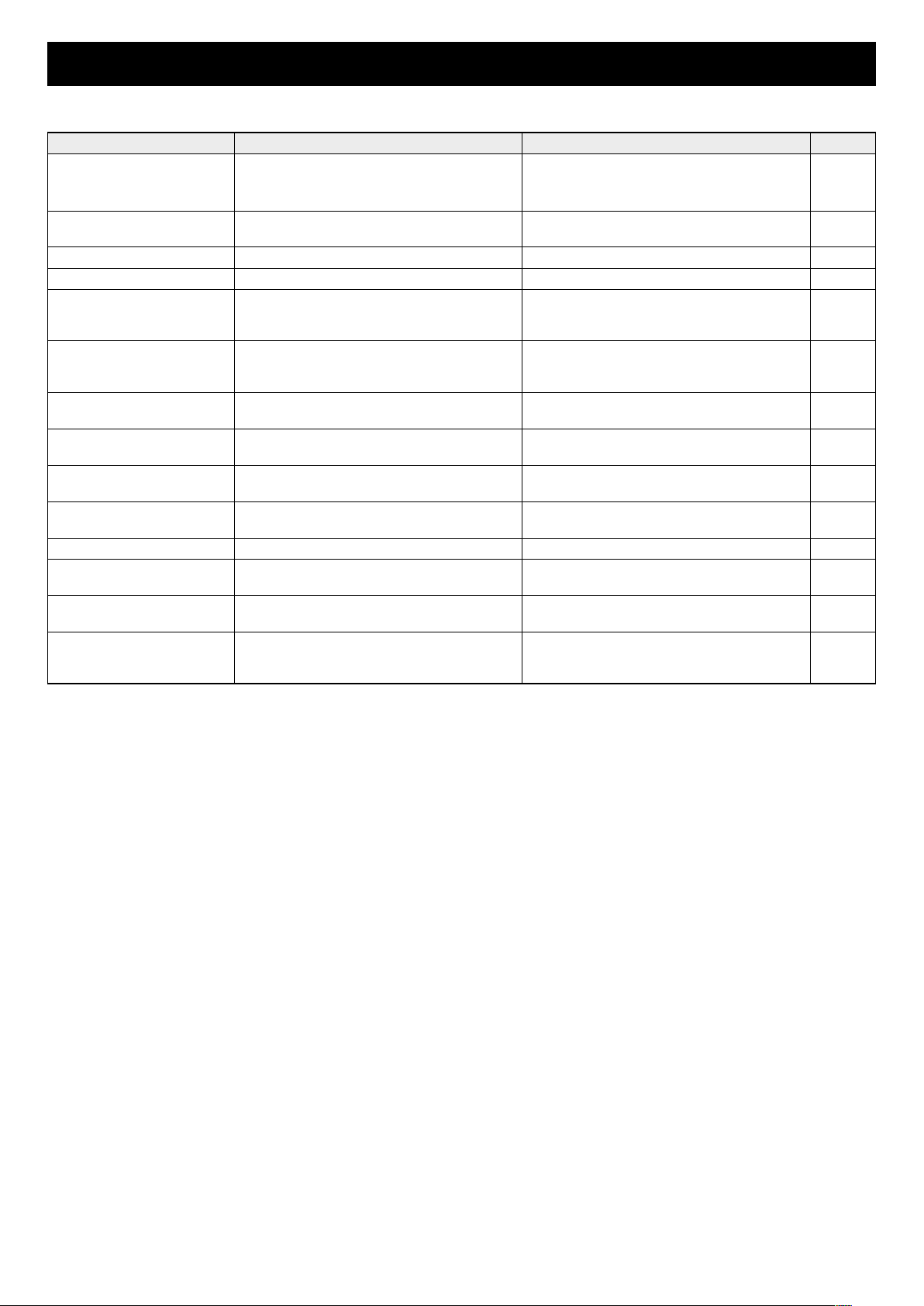
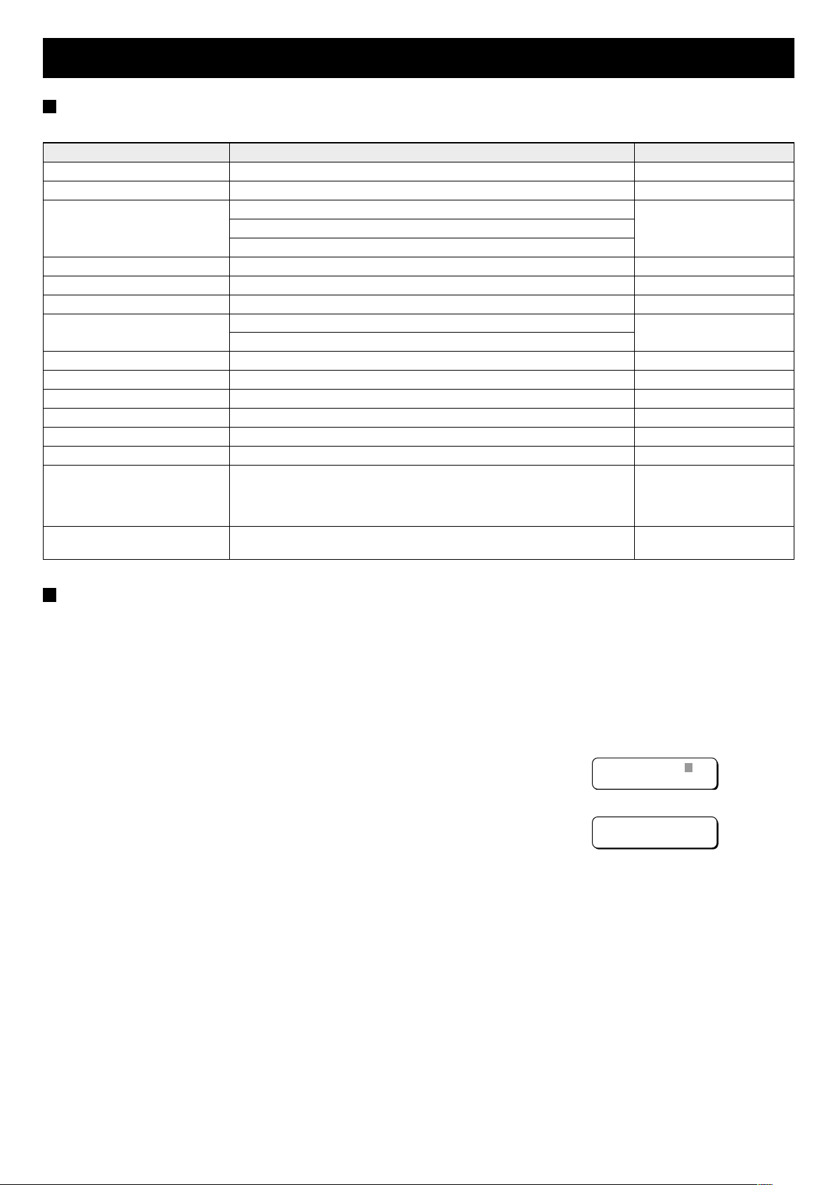
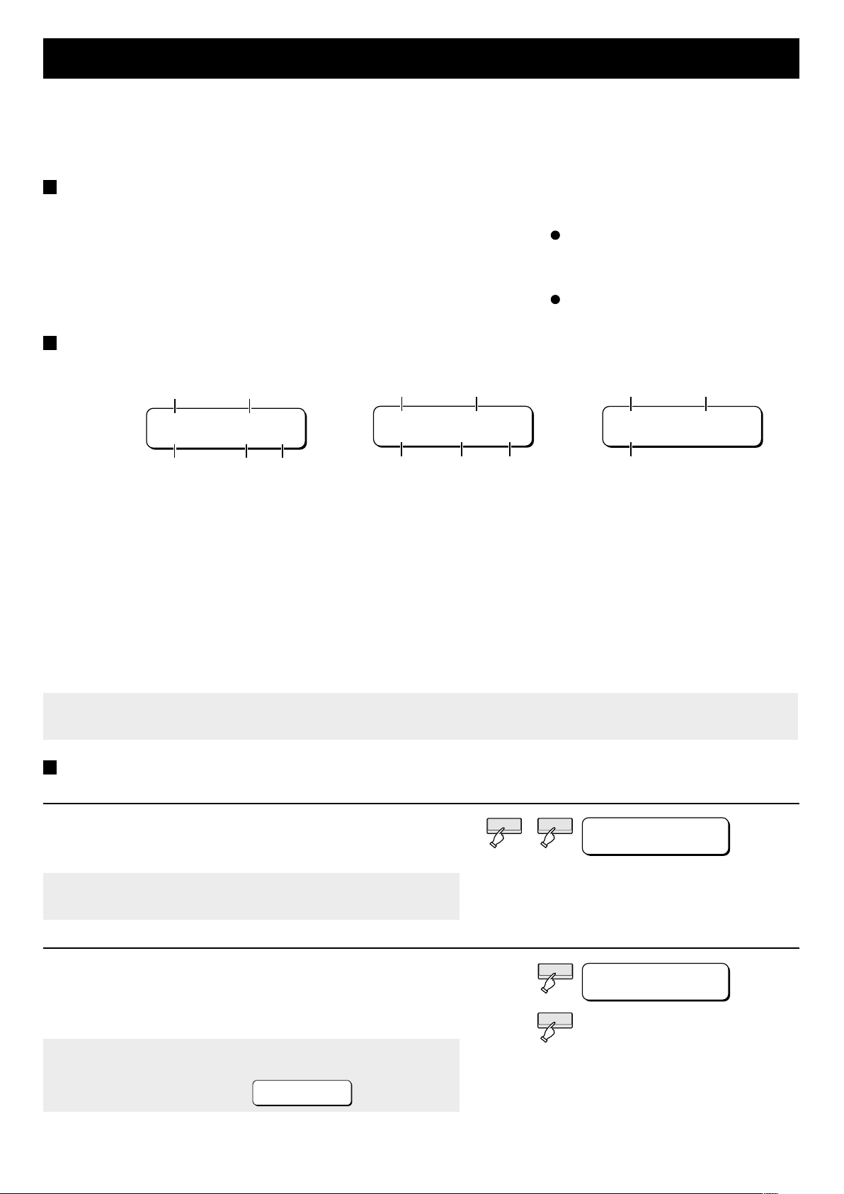
DISPLAY MEANINGS AND REMEDIES
● Menu screen display
Display Meaning Remedy Page
ADDRESS ERROR Address between 5 and 7 was set. Set another address between 0 and 4.
The same address as another controller
was set.
DBL. ADR. Two devices have the same address. Set the address of one of the devices to a
Error (during entry) Entry exceeds existing limits. Reenter value within limits.
Error (during operation) A device is not operating properly. Read the instruction manual of the device. P13
Error
(during connection)
FAIL Requested alarm no., day/hour, or
FIND Requested alarm no., day/hour, or
LOCKED Security lock of unit is activated. Enter the secret code and deactivate
LOCKED BY MASTER Security lock of master controller is
No ADR. Address does not exist (e.g., has not been
NO ALARM Alarm list has no alarm entries. Check alarm list after ALARM lamp flashes. P29
NO CHANGE Status list has no status entries. Check status list after STATUS lamp
unregistered Device is not registered a group. Either specify that device or register it to a
WAITING Bus carrying data to devices is busy and
Though device is in standby, requested
operation was tried three times and could
not be executed.
day/hour/minute recording could not be
found.
day/hour/minute recording was found.
activated.
set).
device will not operate.
different address.
Wait a moment and try again.
security lock.
Deactivate lock at master controller.
Recheck and enter correct address.
flashes.
group.
Device is treated as if in standby and
requested operation will be tried three
times. Wait a moment and try again.
P6
P10
P10
P24
P30
P26
P28
31

SPECIFICATIONS
Communication method : RS 485
Control terminals : RJ-11: 2 terminals
Push-lock: 1 pair
RS-232C port for programming : D-SUB (9-pin): 1 port
Address/termination switch : Address: 3-bit DIP switch
Termination: 1-bit DIP switch
Communication speed (baud rate) : 2400, 4800, 9600, 19,200 bps
Max. no. of groups : 15 groups
Max. no. of connected devices : Total: 256 devices
Controllers: 5 devices
Multiplexers, timelapse VCRs, and cameras: 128 devices each
Ambient conditions : Temperature: 0 to 40˚C
Relative humidity: 80% or less
Storage conditions : Temperature: –20 to 60˚C
Relative humidity: 80% or less
Power supply : 12 V DC
Power consumption :4 W
External dimensions : 376 (W) x 166 (H) x 55 (D) mm
Weight : 1.45 kg
Accessories : AC adapter (1), modular cable (RJ-11, 6-pin, 2-core) (1)
Be aware that the external appearance or specifications are subject to change without notice.
32
 Loading...