

Page 1
2. DISASSEMBLY
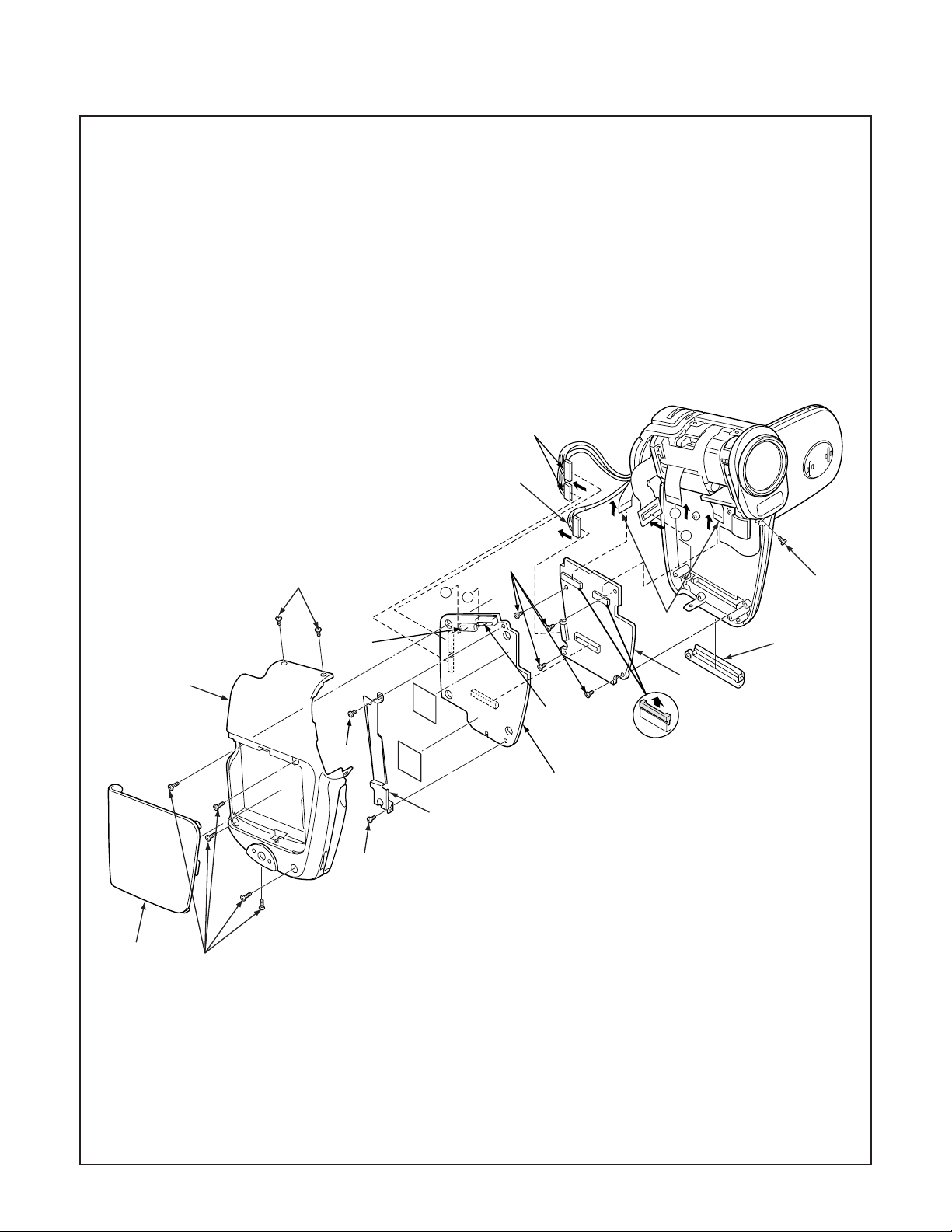
2-1. REMOVAL OF CABINET LEFT, CP1 BOARD AND SY1 BOARD
1. Cover battery
2. Five screws 1.7 x 5
3. Three screws 1.7 x 3
4. Cabinet left
5. Cover card
6. Connector
7. FPC
8. Screw 1.7 x 4
4
9. Screw 1.7 x 3
10. Shield CP1
11. CP1 board
12. Two connectors
13. Two FPCs
14. Four screws 1.7 x 4
15. Connector
16. SY1 board
3
6
9
12
15
B
A
14
A
B
3
13
5
16
7
11
10
8
1
2
– 11 –
Page 2
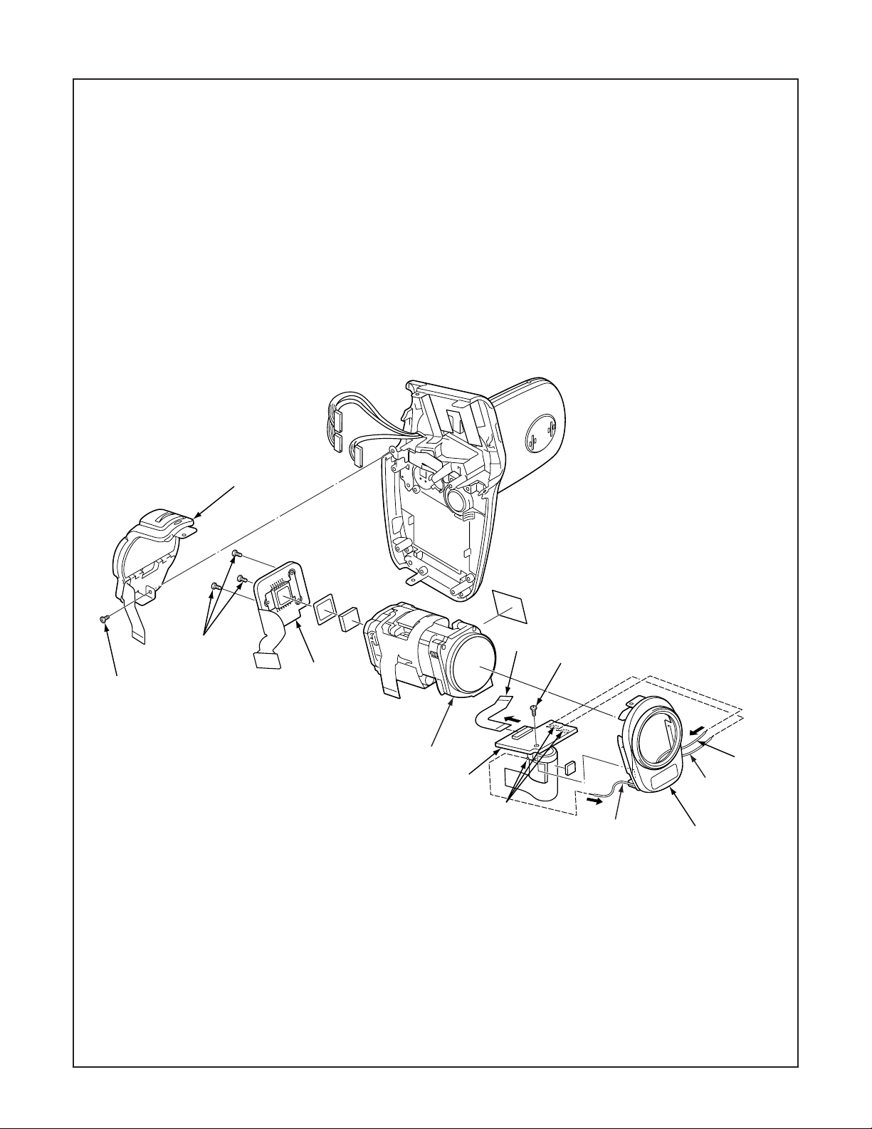
2-2. REMOVAL OF CABINET FRONT, ST1 BOARD AND CA1 BOARD
1. Assy lens
2. Cabinet front
3. Screw 1.7 x 4
4. Flexible PWB
5. Remove the solder.
6. ST1 board
7. Three screws 1.4 x 3.5
8. CA1 board
9. Screw 1.7 x 3
10. Unit control
10
c
b
a
7
9
When assembling,
tighten the screws order.
a → b → c
NOTE: Discharge a strobe capacitor
with the discharge jig (VJ8-0188) for
electric shock prevention.
4
3
8
1
6
black
pink
5
gray
2
– 12 –
Page 3
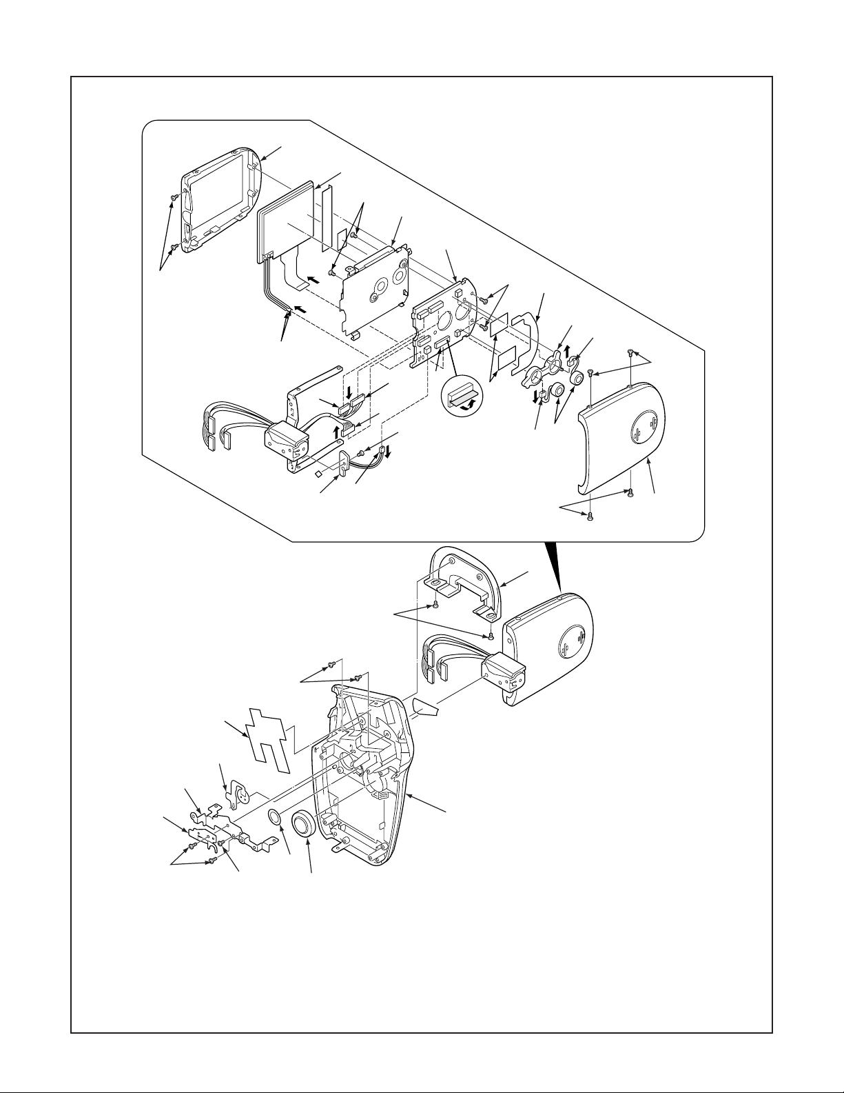
2-3. REMOVAL OF CABINET RIGHT, LCD, VF1 BOARD AND TB1 BOARD
32
25
26
27
28
31
1. Two screws 1.7 x 4
2. Spring button
3. Button LCD
4. Shield tape right
5. Two screws 1.7 x 2.5
6. Two screws 1.7 x 2
7. Assy cover joint base
8. Screw 1.7 x 2.5
24
22
15
29
21
13
23
17
18
16
19
34
33
20
21
13
30
14
7
6
5
4
10
9
2
1
9. Holder joint
10. Assy button power
11. Speaker, 8
12. Cabinet right
13. Four screws 1.4 x 3
19. Assy wire VF1 & SY1
20. Connector
21. Two connectors
22. Two screws 1.7 x 4
23. FPC
12
3
8
11
14. Cover LCD back
15. Shield tape LCD
16. Spacer LCD
17. Assy wire VF1 & CP1-2
18. Assy wire VF1 & CP1-1
– 13 –
24. Remove the solder.
25. LCD
26. Two screws 1.7 x 2.5
27. Holder monitor
28. VF1 board
29. Holder mic
30. Microphone
31. Two screws 1.4 x 3
32. Cover LCD front
33. Screw 1.4 x 2
34. TB1 board
Page 4

2-4. BOARD LOCATION
CA1 board
VF1 board
CP1 board
TB1 board
ST1 board
SY1 board
– 14 –
Page 5

3. ELECTRICAL ADJUSTMENT
Firmware
Data
AWB
Focus
UV Matrix
R Bright
RGB Offset
Tint
B Bright
Gain
Phase
LCD
Calibration
Upload
PAF Cal.
LCD Type
H AFC Test
VCOMDC
VCOMPP
Cal Data
Cal Mode
OK
OK
EVF
USB storage
Get
Set
VID
Set
PID
Set
Serial
Set
Rev.
Set
Setting
Language
Video Mode
VCO
Factory Code
Hall Cal.
Backrush pulse :
Set
Get
3-1. Table for Servicing Tools
Ref. No.
J-1
J-2
J-3
J-4
J-5
J-6
Name
Pattern box (color viewer)
Calibration software
Chroma meter
Spare lump
Discharge jig
Collimator
Number
1
1
1
1
1
1
Part code
VJ8-0190
VJ8-0263
VJ8-0192
VJ8-0191
VJ8-0188
VJ8-0260
3-4. Setup
1. System requirements
Windows 98 or Me or 2000 or XP
IBM R -compatible PC with pentium processor
CD-ROM drive
3.5-inch high-density diskette drive
USB port
40 MB RAM
Hard disk drive with at least 15 MB available
VGA or SVGA monitor with at least 256-color display
Note: J-1 Pattern box (color viewer) is 100 - 110 VAC only.
J-1 J-2
J-3
J-4
J-5
2. Installing calibration software
1. Insert the calibration software installation diskette into your
diskette drive.
2. Open the explorer.
3. Copy the DscCalDI_150 folder on the floppy disk in the FD
drive to a folder on the hard disk.
3. Installing USB driver
Install the USB driver with camera or connection kit for PC.
4. Pattern box (color viewer)
Turn on the switch and wait for 30 minutes for aging to take
place before using Color Pure. It is used after adjusting the
chroma meter (VJ8-0192) adjust color temperature to 3100 ±
20 K and luminosity to 900 ± 20 cd/m
2
. Be careful of handling
the lump and its circumference are high temperature during
use and after power off for a while.
5. Computer screen during adjustment
3-2. Equipment
1. Oscilloscope
2. Digital voltmeter
3. AC adaptor
4. PC (IBM R -compatible PC, Pentium processor, Window
98 or Me or 2000 or XP)
3-3. Adjustment Items and Order
1. IC501 Oscillation Frequency Adjustment
2. Lens Adjustment
3. AWB Adjustment
4. CCD White Point Defect Detect Adjustment
5. CCD Black Point And White Point Defect Detect Adjust-
ment In Lighted
Note: Item 2-5 adjustments should be carried out in sequence.
– 15 –
Page 6

3-5. Connecting the camera to the computer
1. Line up the arrow on the cable connector with the notch on the camera's USB port. Insert the connector.
2. Locate a USB port on your computer.
3. Insert the AC adaptor’s cable to DC jack.
4. Choose the “CARD READER”, and press the SET button.
AC adaptor
To USB port
USB cable
NOTE: Discharge a strobe capacitor
with the discharge jig (VJ8-0188) for
electric shock prevention.
– 16 –
Page 7

3-6. The adjustment item which in necessary in part exchange
CCD Black
Point And White
Point Defect
Detect
Adjustment In
Lighted
Factory
Cord
Setting
Language
Setting
COMPL PWB CP-1
(636 091 3738)
COMPL PWB SY-1
(636 091 3769)
COMPL PWB CA-1
(636 091 3806)
COMPL PWB ST-1
(636 091 3745)
COMPL PWB VF-1
(636 091 3752)
COMPL PWB TB-1
(636 091 4025)
LENS ASSY
(645 082 0519)
IC501
Oscillation
Frequency
Adjustment
Lens
Adjustment
AWB
Adjustment
CCD White
Point Defect
Detect
Adjustment
: Be sure to carry out the necessary adjustments after replacing the unit.
: Adjustment is possible from the menu setting screen of the camera and by using the calibration software.
3-7. Adjust Specifications
[CP1 board (Side B)]
Adjustment method:
1. Adjust with VR501 to 496.5 ± 1 kHz.
USB storage
information
registration
Reset
Setting
VR501
CL501
Note:
1. Frequency adjustment is necessary to repair in the CP1
board and replace the parts.
Preparation:
1. Remove the cabinet left. You can see VR501 and CL501
in the CP1 board.
2. Insert the SD card.
3. Set the main switch to the REC.
4. Press the power button, and comfirm that the through im-
age from CCD can be seen in the LCD.
1. IC501 Oscillation Frequency Adjustment
Measuring Point
Measuring Equipment
ADJ. Location
ADJ. Value
CL501
Frequency counter
VR501
496.5 ± 1 kHz
2. Lens Adjustment
Camera
Collimator
Preparation:
POWER switch: ON
If using a ready-made collimator, set to infinity.
Note:
Do not vibrate during the adjustment.
Adjustment method:
1. Set the camera 0 cm from the collimator. (Do not enter any
light.)
2. Set the camera so that it becomes center of the screen in
the collimator.
3. Double-click on the DscCalDi.exe.
4. Click the Focus, and click the Yes.
5. Lens adjustment value will appear on the screen.
6. Click the OK.
– 17 –
Page 8

DscCalDi
x
Dsc Calibration x
Focus Result
!
STD_AFPOS=1168
FOCUS=-5,-14,-15,-4,-71
ADJ_PZPOS=15
OK
Adjustment value determination is effectuated using the "STD
AFPOS" and "FOCUS" values.
If FOCUS=focus1, focus2, focus3, focus4, focus5 and the ad-
justment values fulfill the conditions below, they are determined
as within specifications.
Adjustment value determination
1050<=STD_AFPOS<1240
-40<=focus1<=+40, -50<focus2<+50,
-60<=focus3<=+60, -60<=focus4<=+60,
-150<=focus5<=+150
3. AWB Adjustment
Camera
Pattern box
(color viewer)
Preparation:
POWER switch: ON
Adjusting method:
1. When setting the camera in place, set it to an angle so that
nothing appears in any part of the color viewer except the
white section. (Do not enter any light.)
2. Double-click on the DscCalDi.exe.
3. Click the AWB, and click the Yes.
4. AWB adjustment value will appear on the screen.
5. Click the OK.
AWB Result:
1:
AGC=187,356,525,694,863
3F_AGC=1,2
WB=276,516,678
CHECK=128,128,141
WB_ND=275, 515, 691
CHECK_ND=128, 128, 142
IRIS_GAIN: 52
IRIS_OFFSET: 153
MS=1705,2101,2378,2934
IRIS=171,156,137,116,109
0
IRIS=0
Adjustment value determination is effectuated using the "AGC",
“CHECK", “CHECK_ND”, "MS", “IRIS”, “IRIS_GAIN” and
“IRIS_OFFSET” values.
If AGC= a1, a2, a3, a4, a5, CHECK= wc0, wc1, wc2,
CHECK_ND= wnc0, wnc1, wnc2, MS= ms1, ms2, ms3, ms4,
IRIS= s1, s2, s3, s4, s5, IRIS_GAIN= g and IRIS_OFFSET=
o the adjustment values fulfill the conditions below, they are
determined as within specifications.
Adjustment value determination
100<a1<250, 250<a2<450, 450<a3<600,
550<a4<800, 750<a5<1024
wc0=128 ± 2, wc1=128 ± 2, wc2=130 ± 40
wnc0=128 ± 2, wnc1=128 ± 2, wnc2=130 ± 40
1400<ms1<=2500, 1700<ms2<=2900, 1800<ms3<=3100,
2300<ms4<=3600
100<=s1<=220, 100<=s2<=220, 100<=s3<=220,
100<=s4<=220, 100<=s5<=220
s1>s2>s3>s4>s5
0<=g<=255
0<=o<=255
Adjustment values other than the above are irrelevant.
OK
Copy
4. CCD White Point Defect Detect Adjustment
Preparation:
POWER switch: ON
Adjustment method:
1. Double-click on the DscCalDi.exe.
2. Select “CCD Defect” on the LCD “Test”, and click the “Ye s ”.
3. After the adjustment is completed, OK will display.
4. Click the OK.
– 18 –
Page 9

5. CCD Black Point And White Point Defect Detect
Firmware
Data
AWB
Focus
UV Matrix
R Bright
RGB Offset
Tint
B Bright
Gain
Phase
LCD
Calibration
Upload
PAF Cal.
LCD Type
H AFC Test
VCOMDC
VCOMPP
Cal Data
Cal Mode
OK
OK
EVF
USB storage
Get
Set
VID
Set
PID
Set
Serial
Set
Rev.
Set
Setting
Language
Video Mode
VCO
Factory Code
Hall Cal.
Backrush pulse :
Set
Get
Adjustment In Lighted
Camera
Pattern box
(color viewer)
Preparation:
POWER switch: ON
Setting of pattern box:
Color temperature: 3100 ± 20 (K)
Luminance: 900 ± 20 (cd/m
Adjusting method:
1. Set the camera 0 cm from the pattern box. (Do not enter
any light.)
2. Double-click on the DscCalDi.exe.
3. Select “CCD Black” on the LCD “Test”, and click the “Ye s ”.
4. After the adjustment is completed, the number of defect
will appear.
2
)
3-8. Factory Code Setting
1. Check the "Factory Code" display within the Setting group.
2. For U.S.A., Canada and NTSC general area
If "FC_SANYO_U" does not appear, click on the " " mark
located on the right of the "Factory Code" display BOX and
select "FC_SANYO_U".
3. For Europe and PAL general area
If "FC_SANYO_EX" does not appear, click on the " " mark
located on the right of the "Factory Code" display BOX and
select "FC_SANYO_EX".
3-9. Language Setting
1. Click on the " " mark located on the right of the
"Language" display BOX.
2. Select language. (Default is English.)
3. End "DscCal" and remove the camera before turning the
camera power OFF.
3-10. Reset Setting
Carry out reset settings after replacing CP1 board.
1. Turn on the camera.
2. Press the MENU button.
3. Choose the OPTION.
4. Choose the RESET SETTINGS, and press the SET
button.
5. Select Yes, and press the SET button.
3-11. The Compulsive boot starting method
1. Keep MENU button, SET button, and SHUTTER button depressed while switching on the power.
2. Connect the camera and the computer with USB cable.
– 19 –
Page 10

3-12. Firmware uploading procedure
1. Uploading the firmware should be carried out if the version
number (COMPL PWB XX-X) on the replacement circuit
board is lower than the version of the distributed firmware.
For XX-X, enter the name of the circuit board containing the
firmware.
2. The firmware is distributed by e-mail in self-extracting archive
format. Change the extension of the distributed file to .EXE
and save it in your preferred folder.
3. When you double-click the saved file, the firmware (binary
file) will be saved in the same folder.
4. The firmware must not be distributed without permission.
1. Overwriting firmware from the SD card
Preparation:
SD card: SD card with firmware rewritten into the root directory
Data: S814Nxxx.BIN (xxx: version)
Overwriting method:
1. Insert the above SD card.
2. Turn on the camera.
3. Set the main switch to the PLAY.
4. Press the MENU button. The playback setting screen appears.
5. Choose the OPTION icon.
6. Choose the FORMAT.
7. Toggle the SET button to the left for 2 seconds. FIRMWARE
UPDATE will display.
8. Choose YES.
9. Press the SET button. Update is starting.
Note:
Do not turn off the camera’s power or remove the SD card
while the firmware is being updated.
The power will turn on automatically after the update is complete.
2. Overwriting firmware from the calibration software
Preparation:
PC with overwriting firmware copied to the preferred folder in
the HD.
Data: S814Nxxx.BIN (xxx: version)
Overwriting method:
1. Connect the camera’s USB/AV terminal to the computer’
USB connector.
2. The USB Connection screen appears on the camera’s LCD
monitor. Choose the “CARD READER”, and press the SET
button.
3. Double-click on the DscCalDi.exe.
4. Click the Firmware.
5. Choose the fimware file to use for overwriting, and click
the Yes.
6. Update is starting. The message will appear, and choose
OK.
7. After the update is complete, disconnect the USB cable
and turn the camera’s power off.
Note:
Do not turn off the camera’s power while the firmware is being updated.
– 20 –
 Loading...