

Page 1
2. DISASSEMBLY
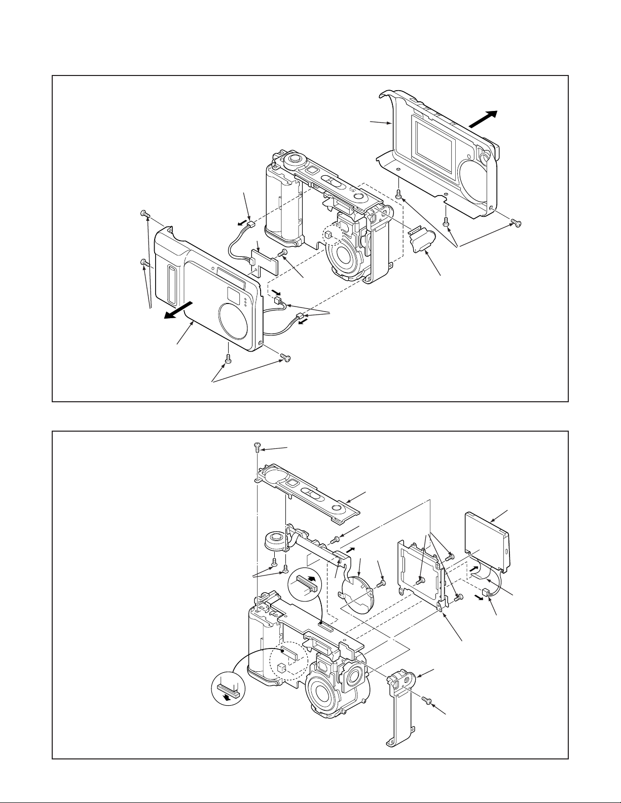
2-1. REMOVAL OF CABINET BACK, CABINET FRONT AND SY2 BOARD
1. Seven screws 1.7 x 4
2. Cabinet back
3. Cabinet front
4. Three connectors
5. Screw 1.7 x 5
6. SY2 board
7. Cover jack
4
6
2
1
1
3
1
2-2. REMOVAL OF CABINET TOP AND LCD
1. Screw 1.7 x 4
2. Cabinet left
3. Screw 1.7 x 2.5
4. Two screws 1.7 x 2.5
5. Cabinet top
6. Screw 1.7 x 3.5
7. Screw 1.7 x 4
8. FPC
9. Unit control panel
10. Connector
11. FPC
12. LCD
13. Three screws 1.7 x 4
14. Holder monitor
4
5
7
4
3
5
12
6
9
7
8
13
11
10
14
2
– 11 –
1
Page 2
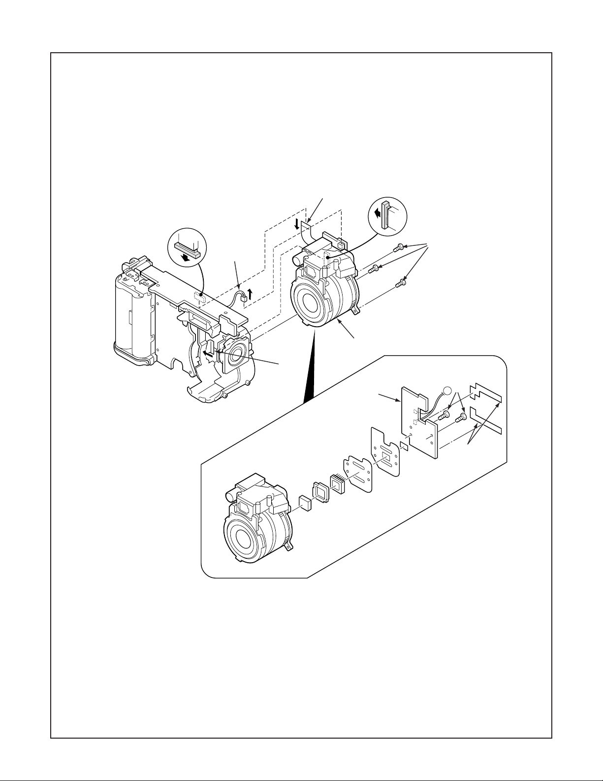
2-3. REMOVAL OF LENS ASSEMBLY AND CA1 BOARD
1
2
4
1. Connector
2. FPC
3. FPC
4. Three screws 1.7 x 4
5. Lens assembly
6. Two screws 1.7 x 5
7. Sheild tape CA1 lens
8. CA1 board
5
3
6
8
E
7
– 12 –
Page 3
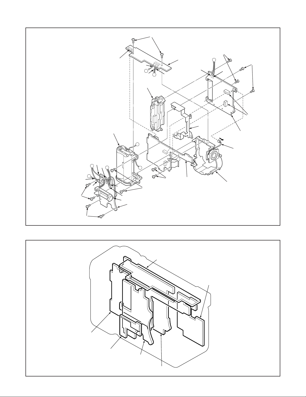
2-4. REMOVAL OF SY1 BOARD, PW1 BOARD, CA3 BOARD AND CA2 BOARD
1
1. Two screws 1.7 x 4
2. Connector
3. SY1 board
4. Four screws 1.7 x 4
5. PW1 board
6. Two screws 1.7 x 3.5
7. Two screws 1.7 x 4
8. Two screws 1.7 x 3.5
9. Holder battery
10. Two connectors
11. Holder card
12. Connector
13. CA3 board
14. Two screws 1.7 x 4
15. CA2 board
16. Holder lens
17. Holder chassis
C
B
red
gray
4
pink
red
2
black
A
white
D
11
9
A
D
blue
white
black
B
6
5
blue
14
3
gray
17
E
15
7
C
pink
8
10
13
12
16
2-5. BOARD LOCATION
4
SY1 board
CA1 board
CA2 board
SY2 board
PW1 board
CA3 board
– 13 –
Page 4

3. ELECTRICAL ADJUSTMENT
3-1. Table for Servicing Tools
Ref. No.
J-1
J-2
J-3
J-4
Note: J-1 color viewer is 100 - 110 VAC only.
Color viewer 5,100 K
Siemens star chart
Calibration software
Spare lamp
Name
Part code
VJ8-0007
VJ8-0184
VJ8-0028
3-4. Setup
1. System requirements
Windows 98 or Me
IBM R -compatible PC with pentium processor
CD-ROM drive
3.5-inch high-density diskette drive
USB port
40 MB RAM
Hard disk drive with at least 15 MB available
VGA or SVGA monitor with at least 256-color display
J-1 J-2
J-3
J-4
3-2. Equipment
1. Oscilloscope
2. Digital voltmeter
3. AC adaptor
4. PC (IBM R -compatible PC, Pentium processor, Window
98 or Me)
3-3. Adjustment Items and Order
1. IC511 Oscillation Frequency Adjustment
2. Lens Adjustment
3. AWB Adjustment
4. Color Adjustment
5. CCD White Point Defect Detect Adjustment
6. CCD Black Point Defect Detect Adjustment
7. LCD Panel Adjustment
7-1. LCD H AFC Adjustment
7-2. LCD RGB Offset Adjustment
7-3. LCD Gain Adjustment
7-4. LCD Red Brightness Adjustment
7-5. LCD Blue Brightness Adjustment
Note: If the lens, CCD and board and changing the part in
item 2-6 replace, it is necessary to adjust again. Item 35 adjustments should be carried out in sequence. Item
6 adjustments should be carried out after item 3.
2. Installing calibration software
1. Insert the calibration software installation diskette into your
diskette drive.
2. Open the explorer.
3. Copy the DscCalDI_128 folder on the floppy disk in the FD
drive to a folder on the hard disk.
3. Installing USB drive
Install the USB drive with camera or connection kit for PC.
4. Color Viewer
1. Turn on the switch and wait for 30 minutes for aging to take
place before using Color Pure.
2. The luminance adjustment control on the color viewer
should be set to around the middle position (memory 5)
during use.
3. The fluorescent lamps which are used in the color viewer
are consumable parts. After the cumulative usage time
reaches 2000 hours, the color temperature will start to increase as the usage time increases, and correct adjustment will not be possible. When the cumulative usage time
reaches 2000 hours, all of the fluorescent lamps should be
simultaneously replaced with new lamps.
5. Computer screen during adjustment
Calibration
AWB
Focus
UV Matrix
Cal Mode
Cal Data
USB storage
VID
Get
PID
Set
OK
OK
Upload
Firmware
Image
Initialize
EVF
LCD Type
LCD
R Bright
RGB Offset
Tint
VCO
H AFC Test
Serial
Set
Set
Rev.
B Bright
Gain
Phase
Set
Set
VCOMDC
VCOMPP
Setting
Language
Video Mode
– 14 –
Page 5

3-5. Connecting the camera to the computer
1. Line up the arrow on the cable connector with the notch on the camera's USB port. Insert the connector.
2. Locate a USB port on your computer.
USB cable
To USB port
AC adaptor
– 15 –
Page 6

3-6. Adjust Specifications
[CA3 board (Side A)]
CL578
VR513
CL407
(CSYNC)
CL402(G)
CL404
(XENB)
CL401(B)
Note:
1. Voltage adjustment is necessary to repair in the CA3 board
and replace the parts.
2. Power voltage set about +3.0 V.
Preparation:
1. Carry out the voltage adjustments disconnecting cabinet
back.
2. Insert the compact flash.
3. Set the main switch to the camera mode.
4. Set the selector dial to the still image shooting mode.
5. Push the power switch, and comfirm that the through screen
from the CCD can be seen on the LCD.
CL403(R)
2. Lens Adjustment
Camera
Preparation:
POWER switch: ON
Adjustment condition:
More than A3 size siemens star chart
Fluorescent light illumination with no flicker
Illumination above the subject should be 400 lux ± 10 %.
Adjustment method:
1. Set the siemens star chart 150 cm ± 3 cm so that it becomes center of the screen.
2. Double-click on the DscCalDi128.
3. Click the Focus, and click the Yes.
4. Lens adjustment value will appear on the screen.
5. Click the OK.
Approx.
150 cm 3 cm
Siemens
star chart
1. IC511 Oscillation Frequency Adjustment
Measuring Point
Measuring Equipment
ADJ. Location
ADJ. Value
Adjustment method:
1. Adjust with VR513 to 495 ± 2 kHz.
CL578
Frequency counter
VR513
495 ± 2 kHz
3. AWB Adjustment
Camera
All white pattern
Color viewer
Preparation:
POWER switch: ON
Adjusting method:
1. When setting the camera in place, set it to an angle so that
nothing appears in any part of the color viewer except the
white section. (Do not enter any light.)
– 16 –
Page 7

2. Double-click on the DscCalDi128.
3. Click the AWB, and click the Yes.
4. AWB adjustment value will appear on the screen.
5. Click the OK.
4. Color Adjustment
6. CCD Black Point Defect Detect Adjustment
Camera
All white pattern
Color viewer
Camera
All white pattern color
viewer and color matrix
adjustment chart
Preparation:
POWER switch: ON
Adjustment method:
1. Set the color adjustment chart to the color viewer.
(Do not enter any light.)
2. Set the color adjustment chart so that it becomes center
of the screen.
3. Double-click on the DscCalDi128.
4. Click the “UV Matrix”, and Click the “Ye s”.
5. Adjustment values will appear on the screen.
6. Click the OK.
5. CCD White Point Defect Detect Adjustment
Preparation:
POWER switch: ON
Adjustment method:
1. Double-click on the DscCalDi128.
2. Select “CCD Defect” on the LCD “Test”, and click the “Ye s”.
3. After the adjustment is completed, the number of defect
will appear.
Preparation:
POWER switch: ON
Adjusting method:
1. When setting the camera in place, set it to an angle so
that nothing appears in any part of the color viewer except the white section. (Do not enter any light.)
2. Double-click on the DscCalDi128.
3. Select “CCD Black” on the LCD “Test”, and click the “Ye s ”.
4. After the adjustment is completed, the number of defect
will appear.
7. LCD Panel Adjustment
[CA3 board (Side A)]
CL578
VR513
CL407
(CSYNC)
CL402(G)
CL404
(XENB)
CL401(B)
CL403(R)
7-1. LCD H AFC Adjustment
Preparation:
POWER switch: ON
Adjusting method:
1. Double-click on the DscCalDi128.
2. Select 0 on the LCD “H AFC”.
3. Apply a trigger using CL407, and adjust LCD “H AFC” so
that the time A from the rising signal at CL407 to the falling signal at CL404 is 5.26 ± 0.2 µsec.
– 17 –
Page 8

○○○○○○○○
○○
A
CL404
CL407
Enlargement
○○○○○○○○
○○
A
CL404
CL407
7-2. LCD RGB Offset Adjustment
Adjusting method:
1. Adjust LCD “RGB Offset” so that the amplitude of the CL402
waveform is 4.0 V ± 0.1 Vp-p.
Note:
7-2. LCD RGB Offset adjustment and 7-3. LCD Gain adjustment should always be carried out first.
VG
CL402 waveform
(VG–0.1) ±
0.05 Vp-p
4.0 V ±
0.1 Vp-p
CL402 waveform
7-3. LCD Gain Adjustment
Adjusting method:
1. Adjust LCD “Gain” so that the amplitude of the CL402 wave-
form is 7.3 V ± 0.3 Vp-p.
Note:
7-2. LCD RGB Offset adjustment should always be carried
out first.
7.3 V ±
0.3 Vp-p
CL403 waveform
7-5. LCD Blue Brightness Adjustment
Adjusting method:
1. Adjust LCD “B Bright” so that the amplitude of the CL401
waveform is (VG+0.2) ± 0.05 Vp-p with respect to the CL402
(VG) waveform.
Note:
7-2. LCD RGB Offset adjustment and 7-3. LCD Gain adjustment have done.
VG
CL402 waveform
CL402 waveform
7-4. LCD Red Brightness Adjustment
Adjusting method:
1. Adjust LCD “R Bright” so that the amplitude of the CL403
waveform is (VG–0.1) ± 0.05 Vp-p with respect to the CL402
(VG) waveform.
(VG+0.2) ±
0.05Vp-p
CL401 waveform
– 18 –
 Loading...