

Page 1

Color CCD Camera
Manual for Remote Operation
by Network Connection
Page 2

Table of Contents
Instruction .........................................................................................2
■ System requirements ......................................................................... 2
Flow of Camera Operation through to Network Operation ..........3
■ User names and operating privileges ............................................... 3
Configuring the TCP/IP Settings on PC .........................................4
Accessing the Camera .....................................................................6
■ Accessing the Camera Using the UPnP Connection
(for Windows XP only)......................................................................... 7
Viewing Live Video (Main Screen Overview) .................................8
Using the Control Panel ..................................................................9
Establishing Voice Communication .............................................11
Selecting the Operating Conditions .............................................12
NETWORK SETTINGS ....................................................................13
CLOCK SETTINGS .........................................................................14
E-MAIL SETTINGS ..........................................................................15
IMAGE TRANSFER SETTINGS ......................................................16
■ For HTTP connection ....................................................................... 16
■ For FTP connection .......................................................................... 17
AUDIO SETTINGS ...........................................................................19
OPTION SETTINGS ........................................................................20
Changing the Camera Settings .....................................................21
Settings List ....................................................................................22
OpenSSL License ...........................................................................25
Specifications..................................................................................27
English 1
Page 3

Instruction
This option board (Network) is an extension board that allows you to connect Sanyo’s CCD camera to your network.
After installing the option board on the camera, you can view live video from the camera using Web browser on your
PC. If you want to view live videos from multiple cameras, install the supplied “VA-SW3050LITE” monitoring software.
■ System requirements
The system requirements for camera operation via network are as follows:
•PC: IBM PC/AT and compatibles
•OS: Windows 2000/Windows XP Home Edition/Windows XP Professional
•CPU: Pentium III (800MHz or higher)
• Memory: 128MB or more
• Network interface: 10Base-T/100Base-TX
• Display card: 1024 x 768 pixels or higher, 16 million colors or higher
• Web browser: Internet Explorer Ver.6.0 or higher
Note:
• LAN cable must be CAT-5 or higher, and no more than 100 m (109.4 yds) in length.
• Image may be delayed and/or audio interrupted, depending on the environment of use.
Copyright notice
This instruction manual is copyrighted by SANYO Electric Co., Ltd. No materials contained in this manual may be
reproduced in any format without the prior permission of the copyright holder.
Microsoft, Windows and Internet Explorer are registered trademarks or trademarks of Microsoft Corporation in the
United States and other countries.
The official name for “Windows” used in this manual is Microsoft
note that the word “Windows” refers to both “Microsoft
®
Windows
Intel and Pentium are registered trademarks or trademarks of Intel Corporation and its subsidiaries in the United
States and other countries.
IBM and IBM PC/AT are trademarks of International Business Machines Corporation.
UPnP is a trademark of UPnP Implementers Corporation, which is established by the UPnP Forum SC.
Java is a trademark of Sun Microsystems, Inc.
All other brands and product names in this manual are the registered trademarks or trademarks of their respective
owners.
XP Operating System”.
®
®
Windows® 2000 Operating System” and “Microsoft®
Windows® Operating System. In this manual,
2 English
Page 4

Flow of Camera Operation through to Network Operation
For detailed instructions on individual procedures, refer to the pages shown below.
1 Installing the option board on the camera
Refer to the supplied “INSTALLATION MANUAL” for how to install the option board on the camera and
make connection using LAN cables.
Refer to
2 Configuring the TCP/IP settings on PC
3 Accessing the camera
Enter your user name and password to access the camera using the Web browser.
4 Viewing live video
After accessing the camera, the live video will be displayed on the main screen.
For an administrative user, also perform the following procedures.
Page 4
Page 6
Page 8
5 Selecting the operating conditions
Using the [MAIN SETTINGS] screen for an administrative user, configure the detailed
settings for administrative operations.
When you access the camera for the first time, be sure to perform the settings on the
[CLOCK SETTINGS] screen (See page 14).
• You can change the settings stored in the camera remotely through the network
connection (See page 21).
■ User names and operating privileges
Two types of user name shown below can access the camera and are authenticated by password during the login
process.
How the user can operate the camera depends on the user name used for accessing the camera.
guest
admin
If a “guest” user tries to perform an operation not included in his privilege, the authentication dialog appears. In this
dialog, entering the user name and password for an administrative user (“admin”) will enable the user to perform all
operations.
The number of users who can access simultaneously
• Up to 16 users can access the camera simultaneously.
• Whatever the number of users accessing the camera simultaneously, only one user can access the camera as an
administrative user (“admin”).
Note:
Up to 16 users can access the camera simultaneously, however, depending on the environment of use, image and
voice renewal may become slower as the number of connected users increases.
Used for general access. Operations are limited to monitoring the live video. Any operations on the
configuration screens are not allowed.
Used for administrative access. Any camera operations and configurations can be made through the
Web browser.
Page 12
English 3
Page 5
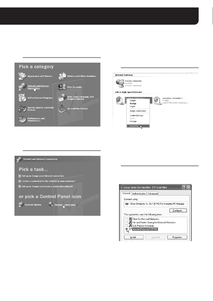
Configuring the TCP/IP Settings on PC
Perform the appropriate TCP/IP settings on your PC in accordance with your operating system.
(The following setting example is for Windows XP.)
In the [Control Panel], click [Network and
1
Internet Connections].
The [Network and Internet Connections] screen
appears.
Click [Network Connections].
2
Right-click on the LAN interface
3
(Ethernet adapter) configuration used
for accessing the camera and click
[Properties] in the context menu.
[General] tab appears in the [Local Area
Connection 2 Properties] dialog box.
In the [This connection uses the
4
following items:] list box, select the
[Internet Protocol (TCP/IP)] check box.
Be sure to confirm that the [Internet Protocol
(TCP/IP)] check box is selected. If the check box
is disabled, select it to enable the option.
The [Network Connections] screen appears.
The LAN interface (Ethernet adapter)
configurations appear in the [LAN or High-Speed
Internet] section.
4 English
Page 6
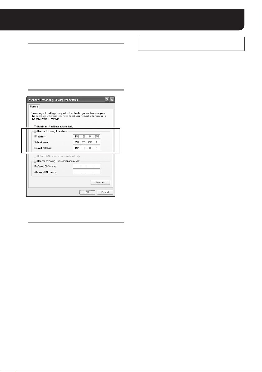
Configuring the TCP/IP Settings on PC
Click [Properties].
5
[General] tab appears in the [Internet Protocol
(TCP/IP) Properties] dialog box.
Select the [Use the following IP
6
address:] radio button and complete the
[IP address:], [Subnet mask:] and
[Default gateway:] fields.
Confirm the settings and click the [OK]
7
button.
This completes the TCP/IP settings. Close all
dialog boxes in the display.
Preparing the Web Browser for Accessing
the Camera
Web browser is required to access the camera. Install
Internet Explorer Ver.6.0 or higher on your PC.
In the cases below, perform the Internet Explorer’s
settings by clicking [Tool] and then [Internet Options].
• When accessing the camera using SSL
encryption for video signal
1 Click the [Advanced] tab.
2 Make sure that the “Use SSL 2.0” and “Use SSL
3.0” options under the “Security” section are
enabled. If disabled, select the options.
• When the video is unstable
1 Click the [General] tab.
2 Under the “Temporary Internet Files” section, click
the [Settings] button.
3 In the “Amount of disk space to use:” setting, set the
lower value.
• When the Java Script’s “Run Time Error” is
displayed
1 Click the [Advanced] tab.
2 Under the “Browsing” section, disable the “Display a
notification about every script error” option.
3 Enable the “Disable script debugging” option.
English 5
Page 7
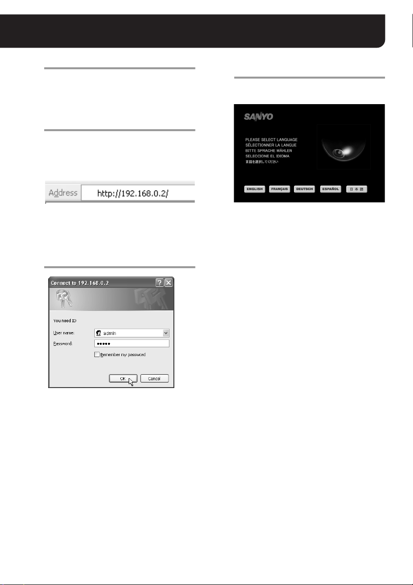
Accessing the Camera
Start the Web browser.
1
To access the camera, Internet Explorer Ver.6.0 or
higher is required.
Type the URL for accessing the camera
2
in the browser’s address bar, and press
[Enter] key.
Type the IP address configured for the camera
following the “http://” characters.
<Example: when the IP address is the factory
setting value>
After accessing the camera, the authentication
dialog appears.
Complete the [User name] and
3
[Password] fields, and click the [OK]
button.
When accessing the camera for the first time, use
the factory setting values below. Using these
values, you will be logged in as an administrative
user.
User name: admin
Password : admin
After the values for the “User name” and
“Password” fields are validated, the language
selection screen appears.
Note:
For security reasons, change the password
regularly.
To change the password, use the [NETWORK
SETTINGS] screen (See page 13).
Select the language used for display,
4
and click the [SET] button.
Available languages:
English, French, German, Spanish, Japanese
After selecting the display language, the main
screen appears and the live video from the
camera is displayed in the video display area.
(From the second time onwards, if the language
selection screen is left for longer than 10 seconds,
the last display language is automatically selected
and the main screen appears.)
MEMO:
• After the camera is turned on, it will take about 1
minute for the camera to be available for accepting
any accesses.
• When you specify the port number for the camera to
a number other than 80, add “:” (colon) and the port
number after the IP address in specifying the URL.
<Example: when
http://192.168.0.2:81/
• When you enable the [SSL] options, type “https://”
instead of “http://” before the IP address when
specifying the URL (See page 13).
“81”
is specified for the port>
Note:
Also while using the supplied “VA-SW3050LITE”
monitoring software or the separately ordered
“VA-SW3050” recorder/player software, you can access
the camera from Web browser simultaneously.
However, when the user who uses the software
performs one of the following actions, other Web-based
concurrent admin users will be disconnected.
• Camera registration
• Alarm settings
6 English
Page 8
Accessing the Camera
■ Accessing the Camera Using the UPnP Connection (for Windows XP only)
When your operating system is Windows XP, you can use the UPnP (Universal Plug and Play)
connection to access the camera.
In the UPnP connection, double-clicking the icon for the camera in the [My Network Places] window will
activate the camera access process. Entering the URL is not required.
● To enable the UPnP component
1 In the [Add or Remove Programs] on the Control
Panel, open [Add/Remove Windows Components].
2 Select “Networking Services” and click [Details].
3 Select the check box for the UPnP component in the
list, and click the [OK] button.
• The UPnP component title in the list should be
either “Universal Plug and Play” or “UPnP User
Interface” depending on your PC.
4 After returning to the [Windows Components
Wizard], click the [Next] button.
5 After the wizard completes, click the [Finish] button.
● Configuring the UPnP connection
In the [OPTION SETTINGS] screen, set the [UPnP]
option to “ON” (See page 20).
• The factory setting value is “ON”.
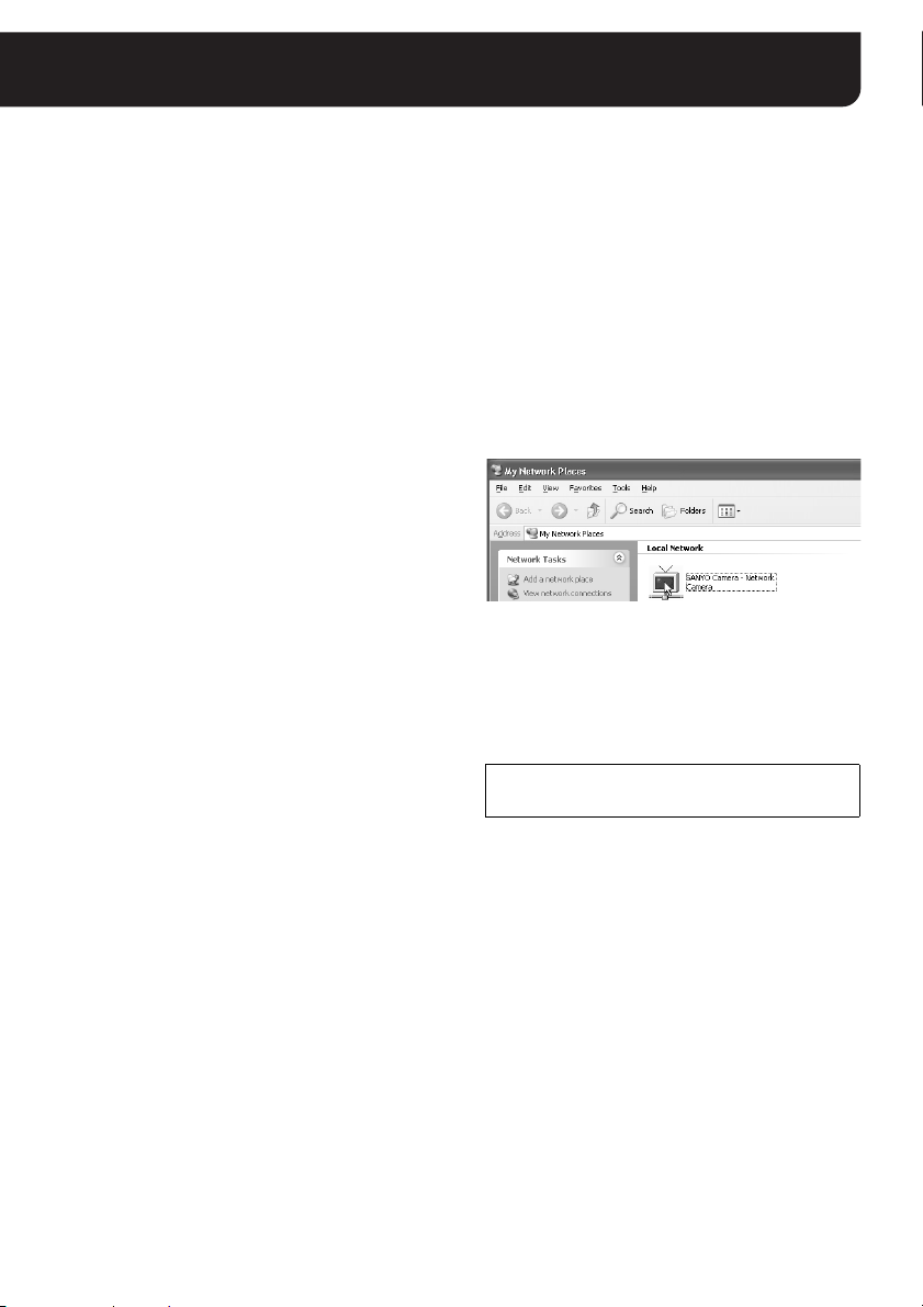
● How to access the camera
1 Open the [My Network Places] window.
The icon for the camera detected on the network
appears in the window.
2 Double-click the icon.
This automatically establishes the connection to the
camera, and the authentication dialog appears.
Display name in the [My Network Places]
window:
SANYO Camera - (camera title)
In the (camera title) section above, the title specified for
the camera in [TITLE] field of the [NETWORK
SETTINGS] screen appears.
If the Security Warning screen
appears
Click “Yes” to allow installation of the “ActiveX control”,
which is necessary for the voice function.
MEMO:
• If the attempt to install “ActiveX control” fails, try
again after selecting [Tools] → [Internet Options] →
[Security] tab from the Internet Explorer and
changing the security level to “Medium” or lower.
• If using WindowsXP SP2, the popup blocker may be
displayed.
Click the information bar to display the popup block
permission menu, then click either “Temporarily
Allow Pop-ups” or “Always Allow Pop-ups from This
Site…”.
English 7
Page 9
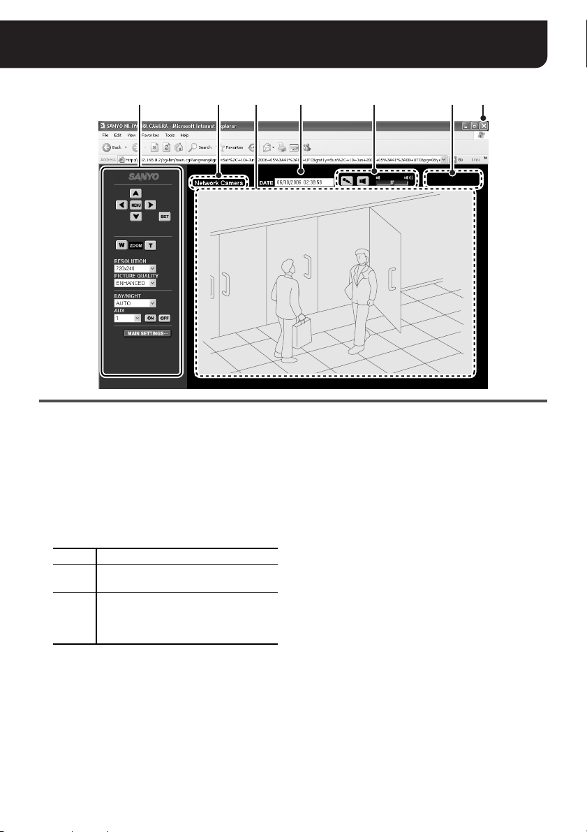
Viewing Live Video (Main Screen Overview)
251 3 4 6 7
1 Control Panel (See pages 9 - 10)
Only the administrative user (“admin”) is allowed to
conduct operations on the control panel.
The control panel layout depends on the camera
model.
2 Camera title (See page 13)
The camera title specified in the [NETWORK
SETTINGS] screen is displayed.
The color of the title changes according to the status
of alarm detection.
White Normal
While alarm is detected or during
Red
recording
While sending or waiting for sending the
Orange
alarm image recorded on the camera to
the VA-SW3050 (HTTP) or FTP server
(FTP)
MEMO:
• When the camera title is in orange, no other
alarms will be processed. When the alarm image
has been sent or the condition that the alarm
image cannot be sent lasts longer than five
minutes, the camera title returns to normal
display (white).
• When the setting for the camera title is blank, the
letters “ALARM” are displayed (in red or orange).
3 Video display area
The live video from the camera is displayed.
MEMO:
For cameras with panning and tilting functions,
clicking the video image changes the camera’s
orientation so that the point where you click is
located at the center of the image.
4 DATE (See page 14)
The date and time specified in the [CLOCK
SETTINGS] screen is displayed.
5 Voice control buttons (See page 11)
Allows you to enable or disable the voice
input/output (send/receive ON/OFF)
respectively as well as adjust the volume.
6 [REMOTE ALARM] button
(only for cameras with panning and tilting functions)
Clicking the [REMOTE ALARM] button activates the
alarm output from the camera. The alarm duration is
subject to the setting on the camera.
7 [Close] button
Click this button to terminate the connection to the
camera and close the screen.
8 English
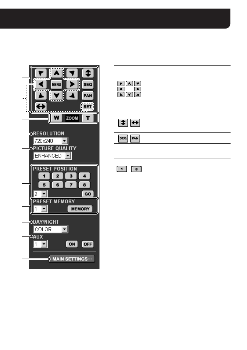
Page 10

Using the Control Panel
A For cameras without panning and tilting functions
(“admin” only)
1
2
3
4
5
6
7
Control Panel
1 Camera configuration buttons (See page 21)
Used for changing the camera settings.
Displays the configuration menu.
Moves the cursor up/down in the configuration
menu.
Moves the cursor to the left/right in the
configuration menu or changes the setting value.
Switches to the next screen or confirms the
settings specified.
2 [ZOOM] buttons
Zooms the camera out.
Zooms the camera in.
3 RESOLUTION
Specifies the video resolution at four levels.
Note:
When either [AUDIO INPUT] and/or [AUDIO OUTPUT] are
configured to “ON” on the [AUDIO SETTINS] screen,
[RESOLUTION] cannot be configured to 640 x 480.
4 PICTURE QUALITY
Specifies the video quality at five levels.
Note:
If [PRE/POST] is set at other than “0%/100%” on the [IMAGE
TRANSFER SETTINGS] screen, the values of [RESOLUTION] and
[PICTURE QUALITY] cannot be changed.
5 DAY/NIGHT (only for the cameras with this function)
Allows you to change the DAY/NIGHT switching conditions
configured using the camera menu.
AUTO
COLOR Always displays the color video image.
B/W Always displays the black-and-white video image.
Switches the video display automatically between
color and black-and-white depending on daytime or
nighttime brightness.
6 AUX
These buttons are reserved for additional functions.
The function corresponding to the number selected in the pull-down
menu will be performed. The function allocated to respective
numbers depends on the camera models.
7 [MAIN SETTINGS] button (See page 12)
Displays the menu buttons for an administrative user (“admin”).
English 9
Page 11
Using the Control Panel (“admin” only)
B For cameras with panning and tilting functions
For the functions common to all camera models (1 - 7), refer to the description on the left page.
1
1
2
3
4
2
3
5
Control Panel
1 Camera control buttons
Changes the camera orientation toward the
direction indicated by arrow mark.
• Clicking the video image changes the
camera’s orientation so that the point
where you click is located at the center of
the image.
The camera control buttons cannot be
operated while the camera configuration
menu is displayed.
Scans the monitored area end to end
vertically or horizontally for respective
buttons, and stops at the current camera
position.
Starts the sequence or auto-panning action
respectively.
2 Calling the preset positions
For camera’s orientation and the zooming and
-
When you call the preset number higher than 8, select the
number from the pull-down menu and click the [GO] button.
3 Registering the preset position
You can register the current camera orientation along with the
zoom and focus settings as the preset position.
To register the preset position, select the number to be used for
current setting from the pull-down menu and click the
[MEMORY] button.
focusing status, calls the preset position
registered in “Registering the preset position”
3) below.
(
6
7
10 English
Page 12

Establishing Voice Communication
You can establish bi-directional voice communication between the camera and PC.
<Camera → PC>
You can view live video with voice because the voice
picked up by the microphone on the camera side is
output to the PC speakers.
You may choose to use an externally connected
microphone or the built-in microphone on the camera.
<PC → Camera>
You may talk to the camera side because the voice
picked up by the microphone on the PC side is output to
the camera speakers.
Only administrative users can talk PC
Connect a microphone and speakers respectively to
the MIC IN and SPEAKER OUT.
Then make sure the following preparations are
completed before operating the voice control buttons for
conducting voice communication.
• A sound card that enables voice output is installed in
the PC (See page 2).
• Voice input/output conditions are configured using
the [AUDIO SETTINGS] screen (See page 19).
→ Camera.
Note:
If voice output from the camera speakers is low,
set “Microphone Boost” to the PC microphone
by the following procedure.
procedure and display names may differ depending on
the environment of use.)
1 Open the [Sounds and Audio Devices] window from
the Control Panel.
2 Select the [Voice] tab and click the [Volume...] button
under [Voice playback].
3 In the [Volume Control] window, select [Properties]
from the Options menu. Select the “Mic Volume”
check box under [Show the following volume
controls:] and click [OK].
4 Click the [Advanced] button under [Mic Volume] (if
no [Advanced] button is shown, select [Advanced
Controls] from the Options menu).
5 In the [Advanced Controls for Mic Volume] window,
select the “Microphone Boost” check box.
(the configuration
Note:
Voice may be prone to interruption depending on the
line conditions. In such cases, adjust the "NETWORK
SPEED" value on the [NETWORK SETTINGS] screen.
Voice control buttons
In order to operate these buttons, configure the
[AUDIO INPUT]/[AUDIO OUTPUT] setting on
the [AUDIO SETTINGS] screen to “ON”.
1 Voice transmission switch button
(“admin” only)
Transmits voice from the PC microphone to the
camera side.
Voice transmission ON
Voice transmission OFF
Note:
Transmission of voice is limited to one administrative
user (admin) at a time.
2 Voice output switch button
Outputs voice from the camera side to the PC.
Voice output ON
Voice output OFF
Note:
When voice output to PC is ON, the maximum
number of simultaneous accesses to the camera is
16.
3 Volume adjustment
The volume adjust slide bar can be used to adjust
the output volume on the PC side.
321
English 11
Page 13

Selecting the Operating Conditions
(“admin” only)
When you click the [MAIN SETTINGS] button on the control panel, the menu buttons for an
administrative user (“admin”) are displayed. Clicking each button displays the corresponding
configuration screen.
1
2
3
4
5
6
7
1 NETWORK (See page 13)
Used for configuring the communication settings
with the camera.
• For the network configurations, contact your
network administrator.
2 CLOCK (See page 14)
Used for configuring the settings related to date and
time.
Be sure to configure the date and time settings
before starting the camera operation through the
network.
3 E-MAIL (See page 15)
You can send the notice e-mail, which tells that the
alarm is detected, to the specified user.
4 TRANSMISSION (See pages 16 - 17)
Used for configuring the recording preferences
when recording the live video using the recorder
software.
You can select the image transfer mode either from
“HTTP” or “FTP”.
5 AUDIO (See page 19)
Used for configuring the voice communication.
Configure the audio settings if you want to listen to
voice from the camera side or send voice from the
PC microphone to the camera side.
6 OPTION (See page 20)
Used for updating the firmware or resetting all the
values to the factory settings.
7 BACK
Returns to the main screen displaying the live video.
MEMO:
For details on the setting preferences, factory settings
and restriction on the number of characters, refer to the
“Settings List” (on page 22).
12 English
Page 14
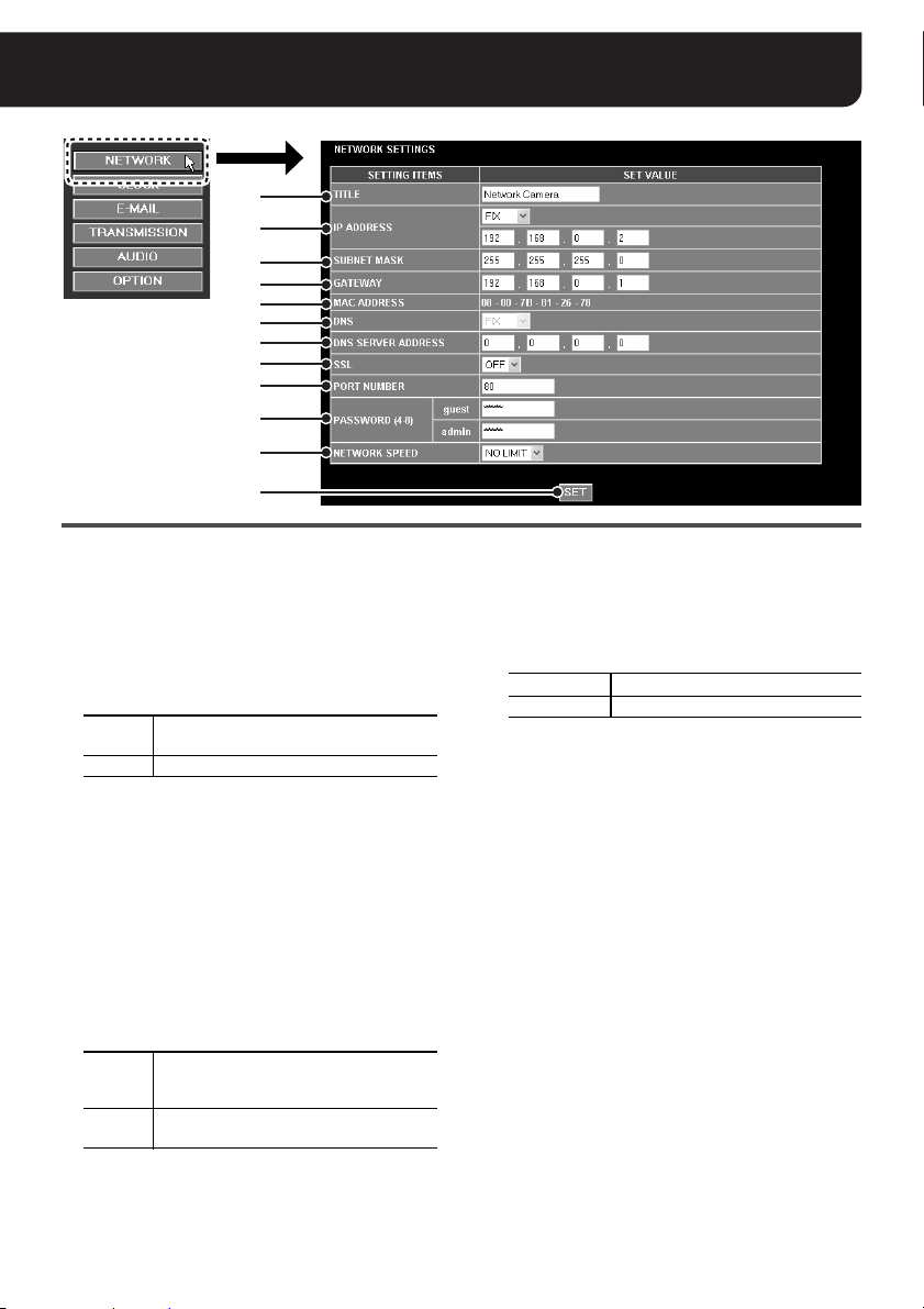
NETWORK SETTINGS
1
2
3
4
5
6
7
8
9
F
G
H
(“admin” only)
1 TITLE
Specifies the camera title.
The title specified here appears in the main screen
and is inserted into the alarm notification e-mail.
The title can be up to 16 alphanumeric characters.
2 IP ADDRESS
Select the method for configuring the camera IP
address.
FIX
DHCP Automatically allocates the IP address.
Manually configure the IP address.
→ Enter the IP address.
3 SUBNET MASK
When the [IP ADDRESS] setting is “FIX”, enter the
subnet mask.
4 GATEWAY
When the [IP ADDRESS] setting is “FIX”, enter the
gateway.
5 MAC ADDRESS
The MAC address of the camera is displayed
automatically.
6 DNS
When the [IP ADDRESS] setting is “DHCP”, select
the method for configuring the DNS server address.
FIX
DHCP
Manually configure the DNS server
address.
→ Enter the DNS server address.
Automatically allocates the DNS server
address.
7 DNS SERVER ADDRESS
When the [DNS] setting is “FIX ”, enter the DNS
server address.
8 SSL
Select “ON” when you want to use the SSL
encryption for the video signal.
9 PORT NUMBER
The default value depends on the preferences
specified in the [SSL] setting above.
SSL (OFF) 80
SSL (ON) 443
You can assign a value between 1 and 65535 to the
SSL port number.
Note:
Set the port number in the range of “1 – 65535” but
make sure that it doesn’t overlap with the [AUDIO
PORT NUMBER] on the [AUDIO SETTINGS]
screen.
F PAS S WO R D
Specify the login password according to each user
name (guest/admin).
MEMO:
When you enter a blank “guest” password (no
password is specified), the authentication process
for accessing the camera will be omitted.
G NETWORK SPEED
Select the data transfer speed in consideration of
the network environment.
H [SET] button
After completing the settings, click this button to
confirm the settings.
To reflect the settings, use the [Close] button to
terminate the camera connection, and then access
the camera again.
English 13
Page 15

CLOCK SETTINGS
1
2
3
4
5
6
(“admin” only)
[REFRESH] button
1 CLOCK SET
Set the date and time for the clock built into the
camera.
2 TIME ZONE
Selects the time zone where the camera is used.
3 DAYLIGHT SAVING MODE
(SUMMER TIME MODE)
Sets the summer time switching mode.
NO USE
AUTO
MANUAL
When “MANUAL” is selected, the summer time
manual setting screen is displayed.
Do not set summer time.
Automatically switches between
standard time and summer time
according to the [TIME ZONE] setting.
Used when manually setting the start
and finish dates and times of summer
time.
4 CLOCK ADJUST
Can be used to adjust date and time automatically.
OFF
ON (NTP)
LOGIN (PC)
Automatic clock adjustment is not
used.
Adjusts the clock automatically by
retrieving the date and time
information from the NTP server.
Adjustment will be made at the
following timing:
• When you turn the camera on
• The time you specified in the
[TIME TO SYNCHRONIZE]
preference (5) (Daily)
Performs the automatic clock
adjustment during login process by
retrieving the date and time
information from the PC used for
accessing the camera.
5 NTP settings
The following configurations can be made only when
the [CLOCK ADJUST] preference is set to “ON
(NTP)”.
• TIME TO SYNCHRONIZE
Specify the time for performing the automatic
clock adjustment.
• REFRESH MANUALLY
When you adjust date and time manually, click
the [REFRESH] button to make adjustment.
• NTP SERVER ADDRESS
Enter the domain name or IP address of the
NTP server used for retrieving the date and time
information.
•LOG
Displays the date and time for the automatic
clock adjustment last performed.
6 [SET] button
After completing the settings, click this button to
confirm the settings.
If you change the setting on the [TIME ZONE] or
[DAYLIGHT SAVING MODE (SUMMER TIME
MODE)] preference, the connection will be
automatically disconnected, and after about
20 seconds it will be established again.
14 English
Page 16

E-MAIL SETTINGS
1
2
3
4
5
6
7
1
(“admin” only)
2
1 SEND MESSAGE
When sending the alarm notification e-mail, set this
value to “ON”.
2 Mail server configuration
The following mail server information is specified in
these setting items.
• SMTP SERVER ADDRESS
(domain name or IP address)
• SMTP PORT NUMBER
(port number used for communicating with the
SMTP server)
3 USER MAIL ADDRESS
Specifies the sender’s e-mail address.
4 RECIPIENT MAIL ADDRESS
Specifies the recipient’s e-mail address to which the
alarm notification is sent. You can specify up to five
e-mail addresses.
1 Type the recipient’s e-mail address and select
the check box to the left of the e-mail address
field.
2 When you want to attach the alarm image to the
e-mail, select the check box for the recipient
under the [ATTACH IMAGE] title.
5 AUTHENTICATION settings
When authentication is required for sending e-mails,
configure the following settings:
• AUTHENTICATION
•USER ID
•PASSWORD
• POP3 SERVER ADDRESS
(domain name or IP address)
6 Editing the alarm notification e-mail
The basic message for the alarm notification e-mail
contains the camera title, the date and time when
the alarm is detected, and the camera’s IP address.
You can configure the following information and add
to the basic message.
• SUBJECT: the title appearing at the
beginning of the message
(up to 32 alphanumeric characters)
• TEXT: additional comment appended to the
basic message (up to 64 alphanumeric
characters)
7 [SET] button
After completing the settings, click this button to
confirm the settings.
English 15
Page 17

IMAGE TRANSFER SETTINGS
(“admin” only)
■ For HTTP connection
When you want to record or play the video in HTTP mode, use the separately ordered “VA-SW3050”
recorder/player software. The recording configuration will be made on the VA-SW3050 screen.
When you use "VA-SW3050", the HTTP mode is automatically selected in the [IMAGE
TRANSMISSION] setting and the FTP mode cannot be used.
1
2
1
3
2
4
1 IMAGE TRANSMISSION
Set the image transfer mode to “HTTP”.
2 LIVE/NORMAL RECORD
Sets the image conditions as well as activates/
deactivates the voice recording for live video and
normal recording.
• RESOLUTION
• QUALITY
•AUDIO
Note:
• When either [AUDIO INPUT] and/or [AUDIO
OUTPUT] are configured to “ON” on the [AUDIO
SETTINS] screen, [RESOLUTION] cannot be
configured to 640 x 480.
• When the [AUDIO INPUT] setting on the [AUDIO
SETTINGS] screen is configured to “OFF”,
[AUDIO] cannot be configured here.
3 ALARM
1
Sets the image conditions as well as activates/
deactivates the voice recording for alarm
recording.
• RESOLUTION (see the “Note” above.)
•QUALITY
• AUDIO (see the “Note” above.)
2 Select the [BUFFER SIZE] option for specifying
the buffering capacity on the camera used for
recording the alarm image. According to the
option you selected, perform the following
settings:
When the [BUFFER SIZE] setting is set from
“0.5MB to 8MB”
One alarm image set containing both the pre- and
post-alarm images is stored in the camera, and then
the alarm image set is transferred one by one to the
“VA-SW3050” software.
Configures the recording capacity ratio
PRE/
between the pre- and post-alarm image
POST
recordings.
Configures the recording rate for the
RATE
alarm image.
Note:
If [PRE/POST] is set at other than “0%/100%”, the
[LIVE/NORMAL RECORD (2)] setting cannot be
changed.
When the [BUFFER SIZE] setting is set to “OFF”
When the alarm is detected, only the post-alarm
images will be transferred to the “VA-SW3050”
software. The transfer speed depends on the
network environment.
Specifies the duration of each alarm
DURATION
image to transfer (During this
duration, no other alarms can be
processed for transferring the alarm
image).
4 [SET] button
After completing the settings, click this button to
confirm the settings.
16 English
Page 18

IMAGE TRANSFER SETTINGS (“admin” only)
■ For FTP connection
1
2
1
3
4
5
1 IMAGE TRANSMISSION
Set the image transfer mode to “FTP”.
2 Configuring the FTP information
The following FTP information is specified in these
setting items.
• PORT NUMBER
Please set the same number as the control port
number configured on the server side. Normally
“21” is set.
Note:
3000 - 5000, 10000, 10001 and 38214 cannot
be set.
• SERVER ADDRESS
• USER ID
• PASSWORD
•FTP PASSIVE
3 ALARM
Configures the operating conditions and camera
1
ID for alarm recording.
• ALARM
Configures alarm recording as ON/OFF.
2
3
• CAMERA ID
This is inserted to the file name of the alarm
recording image. It is also used as the name
of the folder created on the server side.
Note:
If the CAMERA ID is not configured, “sanyo”
and “alarm” are substituted as the file name
and folder name respectively.
• OVERWRITE
Configures whether or not to overwrite file
data transmitted to the FTP server.
Stores all files without conducting
overwrite (date and time information
OFF
is displayed in the file name).
Overwrites (date and time
information is not displayed in the
ON
file name).
Note:
Voice cannot be included in the alarm recording
if the image transfer mode is “FTP”.
English 17
Page 19

IMAGE TRANSFER SETTINGS (“admin” only)
2
Configures the preferences for alarm recording
format.
• RESOLUTION
•QUALITY
Note:
When either [AUDIO INPUT] and/or [AUDIO
OUTPUT] are configured to “ON” on the [AUDIO
SETTINGS] screen, [RESOLUTION] cannot be
configured to 640 x 480.
3 Select the [BUFFER SIZE] option for specifying
the buffering capacity on the camera used for
recording the alarm image. According to the
option you selected, perform the following
settings:
When the [BUFFER SIZE] setting is set
from “0.5MB to 8MB”
One alarm image set containing both the preand post-alarm images is stored in the camera,
and then the alarm image set is transferred one
by one to the FTP server.
Configures the recording capacity ratio
PRE/
between the pre- and post-alarm
POST
image recordings.
Configures the recording rate for the
RATE
alarm image.
Note:
Depending on the shooting conditions, the
number of images that are transferred will differ.
When the [BUFFER SIZE] setting is set to
“OFF”
When the alarm is detected, only the post-alarm
images will be transferred to the FTP server at
the interval you specified in the [TX RATE]
setting. Transfer may not end within the set time
because communication speed may differ
depending on the network or FTP server
environment.
Specifies the duration of each
DURATION
TX RATE
alarm image to transfer (During
this duration, no other alarms
can be processed for transferring
the alarm image).
Configures the interval for
transferring the alarm image
(Select a value shorter than the
[DURATION] setting).
4 TIMER
Configures the operating conditions and camera ID
for timer transmission.
When timer transmission is configured, one image
at a time is automatically transmitted at the interval
that was set in [TX RATE].
•TIMER
Configures timer transmission as ON/OFF.
• CAMERA ID
This is inserted in the file name of
timer-transmitted images. It is also used as the
name of the folder created on the server side.
Note:
If the CAMERA ID is not configured, “sanyo” and
“timer” are substituted as the file name and
folder name respectively.
• OVERWRITE
Configures whether or not to overwrite file data
transmitted to the FTP server.
Stores all files without conducting
overwrite (date and time information is
OFF
displayed in the file name).
Overwrites (date and time information
ON
is not displayed in the file name).
•TX RATE
Configures the image transmission interval.
5 [SET] button
After completing the settings, click this button to
confirm the settings.
MEMO:
The file names of alarm recording images are
composed as follows.
File name = Camera ID_date and time information
(yymmddhhmmss)_4-digit serial number + extension (.jpg)
When [OVERWRITE] is configured to “ON”, date and
time information is not displayed.
18 English
Page 20

AUDIO SETTINGS
1
2
3
4
Note:
When [RESOLUTION] is configured to 640 x 480 on the [IMAGE TRANSFER
SETTINGS] screen, the [AUDIO INPUT]/[AUDIO OUTPUT] setting cannot be
configured to “ON”.
(“admin” only)
1 Settings for voice reception
• AUDIO INPUT
Sets whether or not to input voice from the
camera.
Set to “ON” to listen to voice. You may choose to
use an externally connected microphone
(EXTERNAL) or the built-in microphone on the
camera (INTERNAL).
• MIC SENSITIVITY
Sensitivity for the microphone connected to the
camera can be selected out of eight levels.
• FILTER (500Hz)
Allows you to set a filter for voice.
Limits mechanical noise from cameras with
panning-tilt functions.
2 Settings for voice transmission
• AUDIO OUTPUT
Sets whether or not to output voice to the
speakers connected to the camera. Set to “ON”
when outputting voice from the PC microphone
to the speakers on the camera side.
• OUTPUT LEVEL
Output volume from the speakers connected to
the camera can be selected out of four levels.
•MUTE
When set to “ON”, voice output from the PC
speakers is muted during “PAN/TILT” or “ZOOM”
operation.
3 AUDIO PORT NUMBER
Set the number of the port for voice
communications.
Note:
• The following port numbers cannot be set: 1024
or less, 3000 - 5000, 10000, 10001, and 38214.
• Set the audio port number, making sure that it
doesn’t overlap with the value of the [PORT
NUMBER] on the [NETWORK SETTINGS]
screen.
4 [SET] button
After completing the settings, click this button to
confirm the settings.
English 19
Page 21

OPTION SETTINGS
1
2
3
(“admin” only)
Version number
1 UPnP
When you access the camera through the UPnP
connection, make sure that the [UPnP] option is set
to “ON” (factory setting value).
Note:
• When your operating system is Windows 2000,
you cannot access the camera through the UPnP
connection.
• When you access the camera through the UPnP
connection, enable the UPnP component on your
PC (See page 7).
• After you change the [UPnP] settings, use the
[Close] button to terminate the camera
connection and access the camera again.
After you change the [UPnP] setting from “ON” to
“OFF”, take a note of the camera’s IP address
shown in the [NETWORK SETTINGS] screen so
that you can access the camera from the Web
browser.
2 FIRMWARE UPDATE
You can update the option board firmware to the
latest version.
Click the [SET] button to display the [FIRMWARE
UPDATE] screen.
Click the [Browse...] button to locate the firmware
update file, and click the [EXECUTE] button.
• This starts the firmware update process.
Note:
• Neither make any operations on the screen nor
turn power off while the “LOADING FIRMWARE
FILE...” message is displayed.
• You cannot update the firmware while recording a
video. Trying to update the firmware during
recording causes the operation confirmation
dialog to appear.
When the firmware update completes, the system
restarts automatically. About 90 seconds after the
restart, the connection to the camera will be
established again.
Check the version number indication in the
[OPTION SETTINGS] screen to confirm whether the
firmware update has been successful or not.
3 RESTORING FACTORY SETTINGS
All the settings made in the screens can be reset to
the factory setting values.
Click the [SET] button to display the dialog for
confirming the operation. Click the [OK] button.
20 English
Page 22
Changing the Camera Settings
SYNC
BLC
IRIS
WHITE BALANCE
AGC GAIN
GAMMA
SHUTTER
APERTURE
DAY/NIGHT
OPTION
PRESET
MENU
INT
OFF
SET y
ATW
NORM
0.45
60
HIGH
AUTO y
SET y
OFF
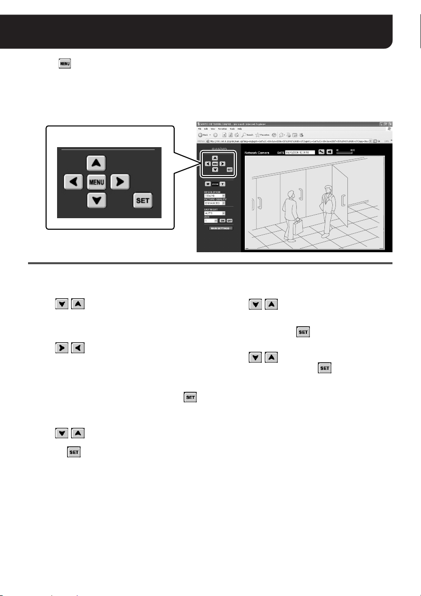
END
(“admin” only)
Clicking on the control panel displays the on-screen camera configuration menu. You can change
the monitoring and operation preferences stored in the camera through the network connection.
MEMO:
The menus displayed depend on the camera model. For details, refer to the instruction manual supplied
with the camera.
The camera configuration
buttons
·SYNC
·SYNC
BLC
BLC
IRIS
IRIS
WHITE BALANCE
WHITE BALANCE
AGC GAIN
AGC GAIN
GAMMA
GAMMA
SHUTTER
SHUTTER
APERTURE
APERTURE
DAY/NIGHT
DAY/NIGHT
OPTION
OPTION
PRESET
PRESET
MENU
MENU
Use the camera configuration buttons on the control panel to change the preferences.
• To select a menu
Click /
to move the cursor up/down. Move
the cursor to locate the menu item you want to
change.
• To change the setting value
Click /
repeatedly to switch the value until
the desired value is displayed.
• To open the submenu
Menu items with y mark have a submenu for
detailed settings.
Move the cursor to your desired menu and click
to open the submenu.
• To return to the previous screen
Click /
to move the cursor to [MENU] at the
bottom of the submenu, set the value to “BACK”,
and click .
• To exit from the menu
Click /
to move the cursor to [MENU] at the
bottom of the menu, make sure that the value is set
to “END” (or change to “END” if “BACK” is
displayed), and click .
• To reset the values to the factory settings
Click /
to move the cursor to [PRESET], set
the value to “ON”, and click
INT
INT
OFF
OFF
SET y
SET y
ATW
ATW
NORM
NORM
0.45
0.45
60
60
HIGH
HIGH
AUTO y
AUTO y
SET y
SET y
OFF
OFF
END
END
.
English 21
Page 23

Settings List
Screen Setting menu Options
Language selection
screen
Main screen
[MAIN SETTINGS] screens
NETWORK
SETTINGS
CLOCK
SETTINGS
E-MAIL
SETTINGS
Display language
RESOLUTION
PICTURE QUALITY
DAY/NIGHT
AUX ON, OFF
TITLE
IP ADDRESS FIX (192.168.0.2), DHCP
SUBNET MASK 255.255.255.0
GATEWAY 192.168.0.1
DNS FIX, DHCP
DNS SERVER ADDRESS 0. 0. 0. 0
SSL OFF, ON
PORT NUMBER
PA SS W OR D
NETWORK SPEED
CLOCK SET Month, day, year, hour, minute
TIME ZONE
DAYLIGHT SAVING MODE
(SUMMER TIME MODE)
CLOCK ADJUST OFF, ON (NTP), LOGIN (PC)
TIME TO SYNCHRONIZE Hour, minute
NTP SERVER ADDRESS – (up to 64 characters)
SEND MESSAGE OFF, ON
SMTP SERVER ADDRESS – (up to 64 characters)
SMTP PORT NUMBER 25
USER MAIL ADDRESS – (up to 64 characters)
RECIPIENT MAIL ADDRESS – (up to 64 characters)
AUTHENTICATION NO USE, POP3, SMTP
USER ID – (up to 48 characters)
PASSWORD – (up to 20 characters)
POP3 SERVER ADDRESS – (up to 64 characters)
SUBJECT – (up to 32 characters)
TEXT – (up to 64 characters)
User name: guest guest (4 to 8 alphanumeric characters)
User name: admin admin (4 to 8 alphanumeric characters)
SSL: OFF 80
SSL: ON 443
ENGLISH, FRANÇAIS, DEUTSCH, ESPAÑOL,
JAPANESE
NTSC:
180 x 120, 360 x 240, 720 x 240, 640 x 480*
PA L:
180 x 143, 360 x 286, 720 x 286, 640 x 480*
BASIC, NORMAL, ENHANCED, FINE, SUPER
FINE
AUTO, COLOR, B/W
(The default value depends on the value set on
the camera side.)
Network Camera
(up to 16 alphanumeric characters)
NO LIMIT, 128K, 256K, 512K, 1M, 2M, 3M, 4M
(bps)
75 zones
GMT Dublin, Edinburgh, Lisbon, London
NO USE, AUTO, MANUAL
1
1
22 English
Page 24

Settings List
Screen Setting menu Options
[MAIN SETTINGS] screens
IMAGE
TRANSFER
SETTINGS
IMAGE TRANSMISSION OFF, HTTP, FTP
LIVE/NORMAL RECORD
NTSC:
RESOLUTION
180 x 120, 360 x 240, 720 x 240, 640 x 480*
PA L:
180 x 143, 360 x 286, 720 x 286, 640 x 480*
QUALITY BASIC, NORMAL, ENHANCED, FINE, SUPER FINE
AUDIO ON, OFF
ALARM
NTSC:
180 x 120, 360 x 240, 720 x 240, 640 x 480*
PA L:
180 x 143, 360 x 286, 720 x 286, 640 x 480*
HTTP
RESOLUTION
QUALITY BASIC, NORMAL, ENHANCED, FINE, SUPER FINE
AUDIO ON, OFF
BUFFER SIZE OFF, 0.5MB, 1MB, 2MB, 4MB, 6MB, 8MB
PRE/POST
RATE
0%/100%, 10%/90%, 20%/80%, 30%/70%, 40%/60%,
50%/50%
NTSC
:
1FPS, 2FPS, 3FPS,
:
PA L
1FPS, 2FPS, 3FPS,
(When you set the [RESOLUTION] preference to “640 x
480”, only the “1FPS”, “2FPS” and “3FPS” options are
available for configuration.)
DURATION
5SEC, 10SEC, 20SEC, 40SEC, 1MIN, 2MIN, 3MIN,
4MIN, 5MIN, 10MIN, 15MIN
PORT NUMBER 21
SERVER ADDRESS – (up to 64 characters)
USER ID – (up to 48 characters)
PASSWORD – (up to 20 characters)
FTP PASSIVE NO USE, USE
ALARM
ALARM ON, OFF
FTP
CAMERA ID – (up to 20 characters)
OVERWRITE ON, OFF
NTSC:
RESOLUTION
180 x 120, 360 x 240, 720 x 240, 640 x 480*
PA L:
180 x 143, 360 x 286, 720 x 286, 640 x 480*
QUALITY BASIC, NORMAL, ENHANCED, FINE, SUPER FINE
BUFFER SIZE OFF, 0.5MB, 1MB, 2MB, 4MB, 6MB, 8MB
PRE/POST
0%/100%, 10%/90%, 20%/80%, 30%/70%, 40%/60%,
50%/50%
5FPS
, 10FPS, 15FPS, 30FPS
5FPS
, 8FPS, 12.5FPS, 25FPS
1
1
1
1
1
1
English 23
Page 25

Settings List
Screen Setting menu Options
[MAIN SETTINGS] screens
IMAGE
TRANSFER
SETTINGS
AUDIO
SETTINGS
OPTION
SETTINGS
*1: When either [AUDIO INPUT] and/or [AUDIO OUTPUT] are configured to “ON” on the [AUDIO SETTINS] screen,
[RESOLUTION] cannot be configured to 640 x 480.
Notes on the “Options” column
• The factory setting value is represented in bold.
• The “–” mark shows that the factory setting value does not exist.
MEMO:
When you want to reset all the settings you made to the factory settings, use the [RESTORING FACTORY SETTINGS]
setting in the [OPTION SETTINGS] screen (See page 20).
ALARM
NTSC
:
1FPS, 2FPS, 3FPS,
:
PA L
RATE
FTP
AUDIO INPUT ON (EXTERNAL), ON (INTERNAL), OFF
MIC SENSITIVITY -3, -2, -1, 0, +1, +2, +3, +4
FILTER (500Hz) ON (-3dB), ON (-6dB), OFF
AUDIO OUTPUT ON, OFF
OUTPUT LEVEL -1, 0, +1, +2
MUTE
AUDIO PORT NUMBER 34341
UPnP ON, OFF
DURATION
TX RATE
TIMER
TIMER ON, OFF
CAMERA ID – (up to 20 characters)
OVERWRITE ON, OFF
TX RATE
PAN/TILT ON, OFF
ZOOM ON, OFF
1FPS, 2FPS, 3FPS,
(When you set the [RESOLUTION] preference to “640 x
480”, only the “1FPS”, “2FPS” and “3FPS” options are
available for configuration.)
5SEC, 10SEC, 20SEC, 40SEC, 1MIN, 2MIN, 3MIN, 4MIN,
5MIN, 10MIN, 15MIN
1SEC, 2SEC, 3SEC, 5SEC, 10SEC, 20SEC, 40SEC,
1MIN, 2MIN, 3MIN, 4MIN, 5MIN, 10MIN, 15MIN
1MIN, 2MIN, 3MIN, 4MIN, 5MIN, 10MIN, 15MIN, 30MIN,
1HOUR, 2HOUR, 3HOUR, 4HOUR, 5HOUR, 6HOUR,
7HOUR, 8HOUR, 12HOUR, 24HOUR
5FPS
, 10FPS, 15FPS, 30FPS
5FPS
, 8FPS, 12.5FPS, 25FPS
24 English
Page 26

OpenSSL License
The following license is applied to OpenSSL.
LICENSE ISSUES
==============
The OpenSSL toolkit stays under a dual license, i.e. both the conditions of
the OpenSSL License and the original SSLeay license apply to the toolkit.
See below for the actual license texts. Actually both licenses are BSD-style
Open Source licenses. In case of any license issues related to OpenSSL
please contact openssl-core@openssl.org.
OpenSSL License
---------------
/* ====================================================================
* Copyright (c) 1998-2003 The OpenSSL Project. All rights reserved.
*
* Redistribution and use in source and binary forms, with or without
* modification, are permitted provided that the following conditions
* are met:
*
* 1. Redistributions of source code must retain the above copyright
* notice, this list of conditions and the following disclaimer.
*
* 2. Redistributions in binary form must reproduce the above copyright
* notice, this list of conditions and the following disclaimer in
* the documentation and/or other materials provided with the
* distribution.
*
* 3. All advertising materials mentioning features or use of this
* software must display the following acknowledgment:
* “This product includes software developed by the OpenSSL Project
* for use in the OpenSSL Toolkit. (http://www.openssl.org/)”
*
* 4. The names “OpenSSL Toolkit” and “OpenSSL Project” must not be used to
* endorse or promote products derived from this software without
* prior written permission. For written permission, please contact
* openssl-core@openssl.org.
*
* 5. Products derived from this software may not be called “OpenSSL”
* nor may “OpenSSL” appear in their names without prior written
* permission of the OpenSSL Project.
*
* 6. Redistributions of any form whatsoever must retain the following
* acknowledgment:
* “This product includes software developed by the OpenSSL Project
* for use in the OpenSSL Toolkit (http://www.openssl.org/)”
*
* THIS SOFTWARE IS PROVIDED BY THE OpenSSL PROJECT ‘‘AS IS’’ AND ANY
* EXPRESSED OR IMPLIED WARRANTIES, INCLUDING, BUT NOT LIMITED TO, THE
* IMPLIED WARRANTIES OF MERCHANTABILITY AND FITNESS FOR A PARTICULAR
* PURPOSE ARE DISCLAIMED. IN NO EVENT SHALL THE OpenSSL PROJECT OR
* ITS CONTRIBUTORS BE LIABLE FOR ANY DIRECT, INDIRECT, INCIDENTAL,
* SPECIAL, EXEMPLARY, OR CONSEQUENTIAL DAMAGES (INCLUDING, BUT
* NOT LIMITED TO, PROCUREMENT OF SUBSTITUTE GOODS OR SERVICES;
* LOSS OF USE, DATA, OR PROFITS; OR BUSINESS INTERRUPTION)
* HOWEVER CAUSED AND ON ANY THEORY OF LIABILITY, WHETHER IN CONTRACT,
* STRICT LIABILITY, OR TORT (INCLUDING NEGLIGENCE OR OTHERWISE)
* ARISING IN ANY WAY OUT OF THE USE OF THIS SOFTWARE, EVEN IF ADVISED
* OF THE POSSIBILITY OF SUCH DAMAGE.
* ====================================================================
*
* This product includes cryptographic software written by Eric Young
* (eay@cryptsoft.com). This product includes software written by Tim
English 25
Page 27

OpenSSL License
G * Hudson (tjh@cryptsoft.com).
*
*/
Original SSLeay License
-----------------------
/* Copyright (C) 1995-1998 Eric Young (eay@cryptsoft.com)
* All rights reserved.
*
* This package is an SSL implementation written
* by Eric Young (eay@cryptsoft.com).
* The implementation was written so as to conform with Netscapes SSL.
*
* This library is free for commercial and non-commercial use as long as
* the following conditions are aheared to. The following conditions
* apply to all code found in this distribution, be it the RC4, RSA,
* lhash, DES, etc., code; not just the SSL code. The SSL documentation
* included with this distribution is covered by the same copyright terms
* except that the holder is Tim Hudson (tjh@cryptsoft.com).
*
* Copyright remains Eric Young’s, and as such any Copyright notices in
* the code are not to be removed.
* If this package is used in a product, Eric Young should be given attribution
* as the author of the parts of the library used.
* This can be in the form of a textual message at program startup or
* in documentation (online or textual) provided with the package.
*
* Redistribution and use in source and binary forms, with or without
* modification, are permitted provided that the following conditions
* are met:
* 1. Redistributions of source code must retain the copyright
* notice, this list of conditions and the following disclaimer.
* 2. Redistributions in binary form must reproduce the above copyright
* notice, this list of conditions and the following disclaimer in the
* documentation and/or other materials provided with the distribution.
* 3. All advertising materials mentioning features or use of this software
* must display the following acknowledgement:
* “This product includes cryptographic software written by
* Eric Young (eay@cryptsoft.com)”
* The word ‘cryptographic’ can be left out if the rouines from the library
* being used are not cryptographic related :-).
* 4. If you include any Windows specific code (or a derivative thereof) from
* the apps directory (application code) you must include an acknowledgement:
* “This product includes software written by Tim Hudson (tjh@cryptsoft.com)”
*
* THIS SOFTWARE IS PROVIDED BY ERIC YOUNG ‘‘AS IS’’ AND
* ANY EXPRESS OR IMPLIED WARRANTIES, INCLUDING, BUT NOT LIMITED TO, THE
* IMPLIED WARRANTIES OF MERCHANTABILITY AND FITNESS FOR A PARTICULAR PURPOSE
* ARE DISCLAIMED. IN NO EVENT SHALL THE AUTHOR OR CONTRIBUTORS BE LIABLE
* FOR ANY DIRECT, INDIRECT, INCIDENTAL, SPECIAL, EXEMPLARY, OR CONSEQUENTIAL
* DAMAGES (INCLUDING, BUT NOT LIMITED TO, PROCUREMENT OF SUBSTITUTE GOODS
* OR SERVICES; LOSS OF USE, DATA, OR PROFITS; OR BUSINESS INTERRUPTION)
* HOWEVER CAUSED AND ON ANY THEORY OF LIABILITY, WHETHER IN CONTRACT, STRICT
* LIABILITY, OR TORT (INCLUDING NEGLIGENCE OR OTHERWISE) ARISING IN ANY WAY
* OUT OF THE USE OF THIS SOFTWARE, EVEN IF ADVISED OF THE POSSIBILITY OF
* SUCH DAMAGE.
*
* The licence and distribution terms for any publically available version or
* derivative of this code cannot be changed. i.e. this code cannot simply be
* copied and put under another distribution licence
* [including the GNU Public Licence.]
*/
26 English
Page 28

Specifications
Image compression JPEG
NTSC:
720 x 240, 640 x 480 (disabled during voice communications),
Resolution
Picture quality 5 levels
Frame rate
Voice compression
method
Microphone input -62 to -32 dB (monaural microphone) 3.5 φ mini jack
Voice output LINE OUT monaural voice output Maximum -8 dBs 3.5 φ mini jack
Voice encryption system PCM 16 bit
Bandwidth 128, 256, 512 Kbps, 1, 2, 3, 4 Mbps, no limitation
Alarm buffer Up to 8 MB; configurable
Interface 10BASE-T/100BASE-TX (RJ45 connector)
PoE support Compliant with IEEE802.3af
Protocol TCP, UDP, HTTP, HTTPS, SMTP, NTP, DHCP, FTP, UPnP
Simultaneous access
capacity
Security BASIC authentication (ID/password), SSL supported (Image only)
360 x 240, 180 x 120
PA L :
720 x 286, 640 x 480 (disabled during voice communications),
360 x 286, 180 x 143
NTSC: Max. 30 fps (720 x 240)
PAL: Max. 25 fps (720 x 286)
G. 711 (192 Kbps), full duplex
Image: Maximum 16, Voice: Maximum 16 (admin: 1)
Printed on recycled paper
1AC6P1P3016--
1AC6P1P3126-L5BP2/US, XE L5BQ2/US, XE (0806KP)
SANYO Electric Co., Ltd.
 Loading...