

Page 1
INSTALLATION MANUAL
Color CCD Camera
THIS INSTALLATION SHOULD BE MADE BY A QUALIFIED
SERVICE PERSON AND SHOULD CONFORM TO ALL LOCAL
CODES.
VCC-XZN600P
VCC-XZ600P
Please read this installation manual carefully in order to ensure correct installation. In addition,
be sure to read carefully the electronic manual contained in the CD-ROM to ensure correct
operation of the camera.
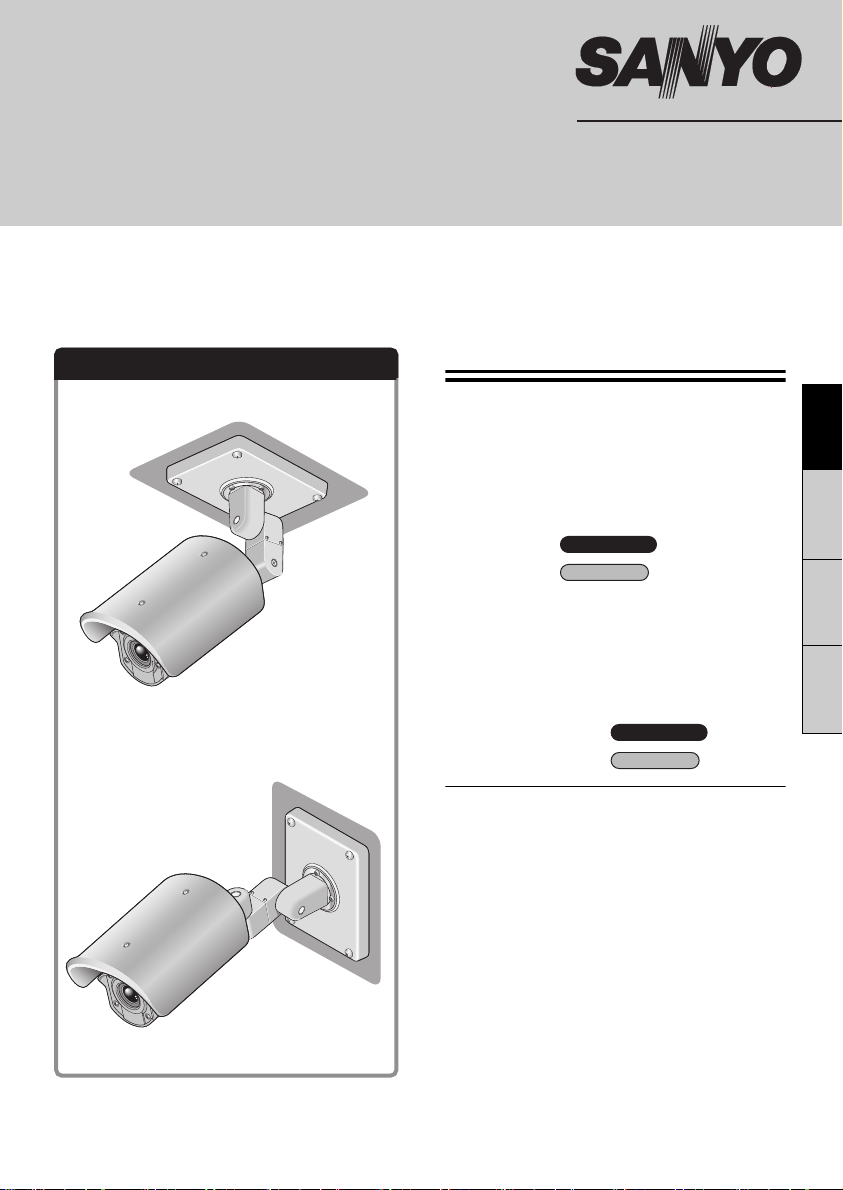
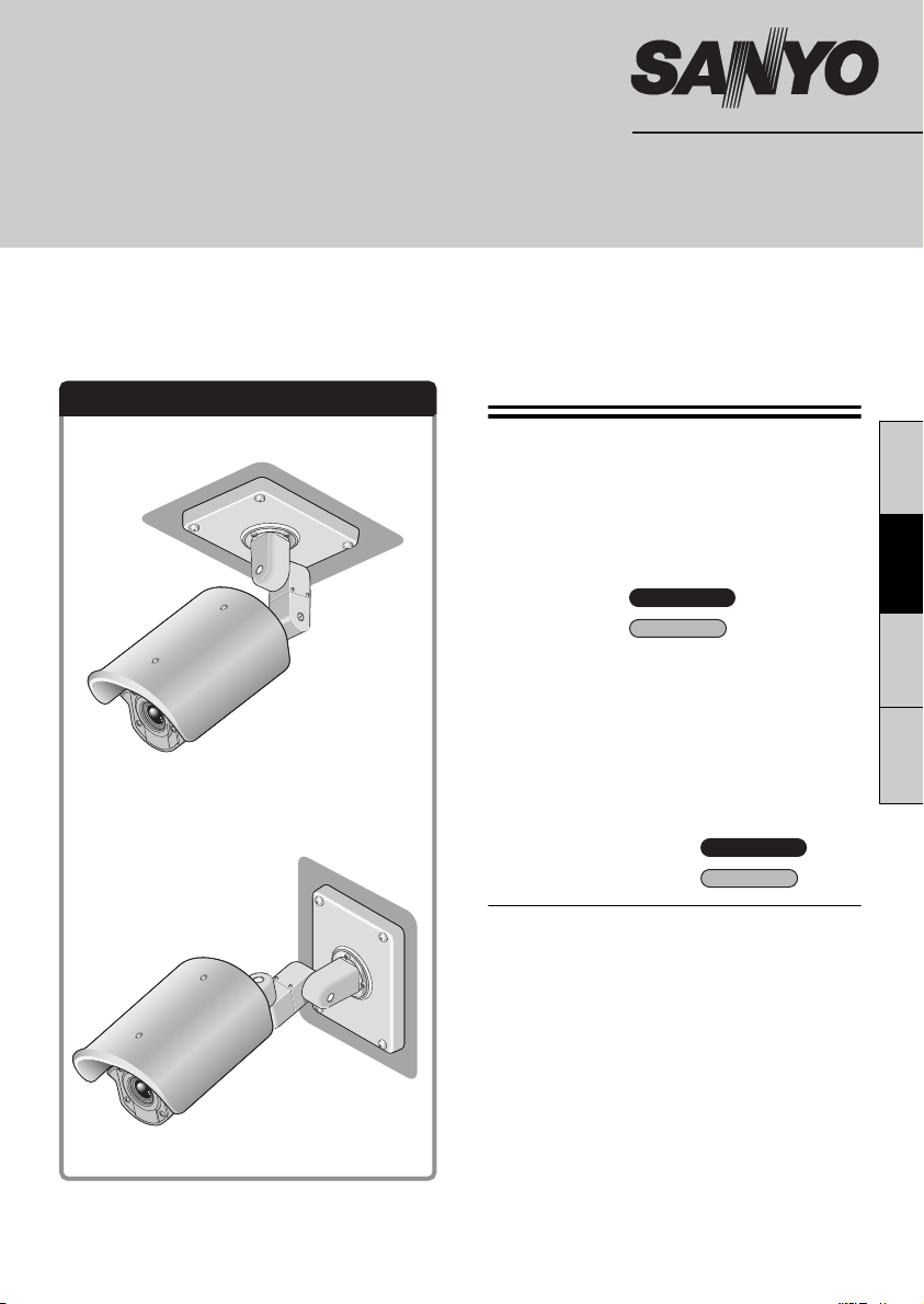
Installation examples
(When installing to a ceiling)
(When installing to a wall)
Contents
Information To User. . . . . . . . . . . . . . . . . . . . 1
Installation method . . . . . . . . . . . . . . . . . . . . 3
Checking the menus and zoom position
using simple monitor output . . . . . . . . . . . . 5
Desiccant for preventing humidity . . . . . . . 6
Connections 1 . . . . . . . . . . . . 7
Connections 2 . . . . . . . . . . . . 11
Features . . . . . . . . . . . . . . . . . . . . . . . . . . . . 13
How to Perform the Settings in the Menu
Screens . . . . . . . . . . . . . . . . . . . . . . . . . . . . 15
Learning the Menu Setting Operations . . . 16
Using the Electronic Manual (CD-ROM) . . 18
Main specifications 1 . . . . . 19
Main specifications 2 . . . . . . . 20
& Inserted at the end of this manual
• Pattern Sheet
• Accessories
Dimensions . . . . . . . . . . . . . . . . . . Back page
VCC-XZN600P
VCC-XZ600P
VCC-XZN600P
VCC-XZ600P
EnglishFrançaisDeutsch中文简体
MEMO:
This installation manual covers two models. Any
difference among the two models is indicated
when necessary.
Page 2

Information To User
Be sure to observe the
following
• Be extremely careful when carrying out
work such as drilling holes in order to install
this camera. In addition, pull out cables
such as the power cable and video cable so
that they can be easily routed.
• When installing the camera, take proper
steps to ensure that the ceiling or wall is
waterproof.
• Select a ceiling or wall surface which is flat
and durable and which can support the full
weight of the camera. If installing to a
curved surface or a round pole or similar,
use a commercially-available mounting
bracket to install the camera.
• Install the camera in a place where the
ambient temperature (with power source
connected) is within -20°C - 50°C/-4°F +122°F. (Condensation should not form.)
• If direct sunlight will shine onto the camera,
install the accessory sunshade.
Precautions
■ In case of a problem
Do not use the unit if smoke or a strange odor
comes from the unit, or if it seems not to function
correctly. Turn off the power immediately and
disconnect the power cord, and then consult your
dealer or an Authorized Sanyo Service Center.
■ Do not open or modify
Do not open the cabinet, as it may be dangerous
and cause damage to the unit. For repairs,
consult your dealer or an Authorized Sanyo
Service Center.
■ Do not put objects inside the unit
Make sure that no metal objects or flammable
substance get inside the unit. If used with a
foreign object inside, it could cause a fire, a
short-circuit or damage. Be careful to protect the
unit from rain, sea water, etc. If water or liquid
gets inside the unit, turn off the power
immediately and disconnect the power cord, and
then consult your dealer or an Authorized Sanyo
Service Center.
■ Be careful when handling the unit
To prevent damage, do not drop the unit or
subject it to strong shock or vibration.
■ Do not install this unit close to magnetic
fields
The magnetic fields may result in unstable
operation.
■ Protect from humidity and dust
To prevent damage, do not install the unit where
there is greasy smoke or steam, where the
humidity may get too high, or where there is a lot
of dust.
■ Protect from high temperatures
Do not install close to stoves, or other heat
sources, such as spotlights, etc., or where it could
be subject to direct sunlight, as this could cause
deformation, discoloration or other damage.
Be careful when installing close to the ceiling, in
a kitchen or boiler room, as the temperature may
rise to high levels.
■ Cleaning
• Dirt can be removed from the cabinet by wiping
it with a soft cloth. To remove stains, wipe with
a soft cloth moistened with a soft detergent
solution and wrung dry, then dry by wiping with
a soft cloth.
• Do not use benzine, thinner or other chemical
products on the cabinet, as this may cause
deformation and paint peeling. Before using a
chemical cloth, make sure to read all
accompanying instructions. Make sure that no
plastic or rubber material comes into contact
with the cabinet for a long period of time, as
this may cause damage or paint peeling.
■ Approvals: IP66/CE
This unit has been certified to IP66 standards
when properly installed.
Use only an IP66 certified enclosure or an
electrical box.
Ensure all openings in enclosure are sealed as
per manufacturer's instructions.
1
Page 3

For EU Users For Russian Users
Please note:
Your SANYO product is designed and
manufactured with high quality
materials and components which can
be recycled and reused.
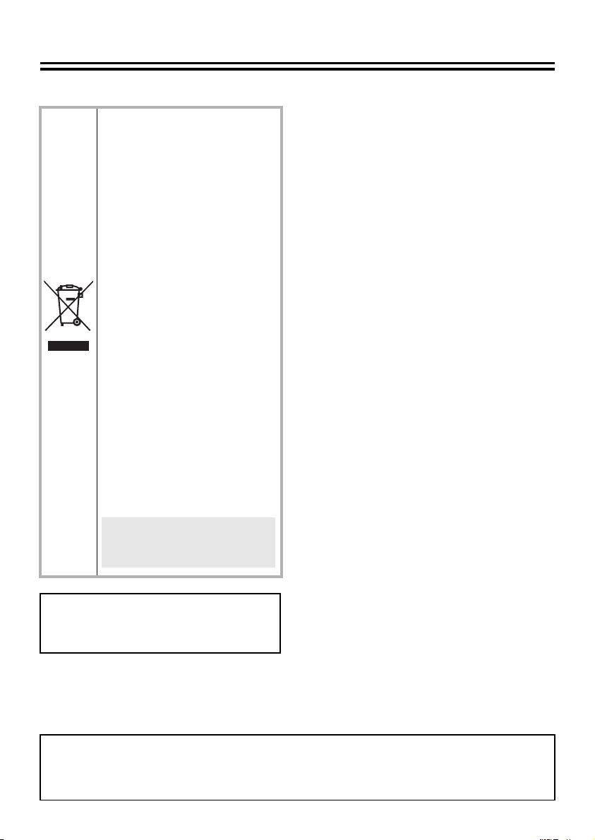
This symbol means that electrical and
electronic equipment, at their
end-of-life, should be disposed of
separately from your household waste.
Please dispose of this equipment at
your local community waste collection/
recycling centre.
In the European Union there are
separate collection systems for used
electrical and electronic products.
Please help us to conserve the
environment we live in!
This symbol mark and recycle
system are applied only to EU
countries and not applied to the
countries in the other area of the
world.
SANYO FISHER Sales (Europe) GmbH
Stahlgruberring 4, D-81829 München, Germany
SANYO Electric Co., Ltd.
1-1, Sanyo-cho, Daito City, Osaka 574-8534, Japan
This product certified by official
certification company which is
authorized by Russian Federation.
ДЛЯ ПОЛЬЗОВАТЕЛЕЙ
РОССИЯ
Данная продукция
сертифицирована официальным
органом по сертификации
Российской Федерации.
This installation manual and the electronic manual are copyrighted by SANYO Electric Co., Ltd.
No materials contained in these manuals may be reproduced in any format without the prior
permission of the copyright holder.
2
Page 4
Installation method
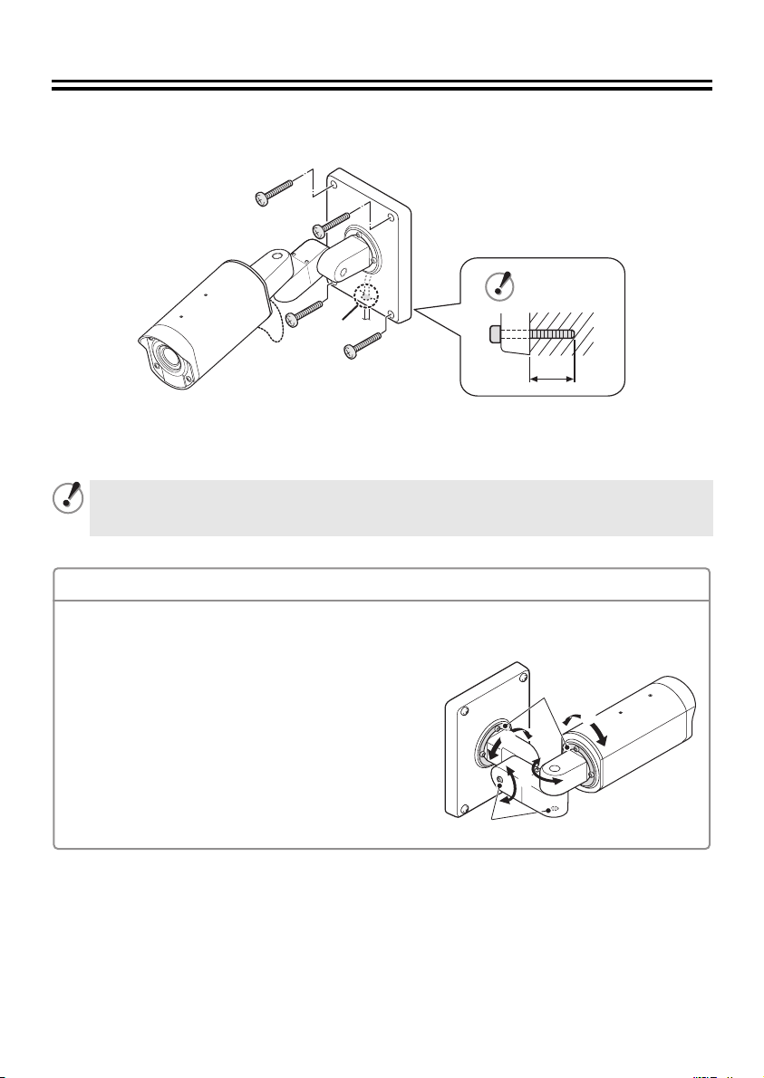
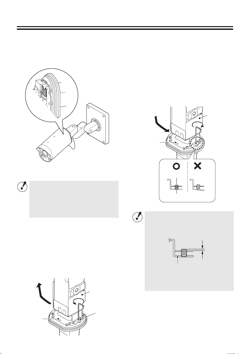
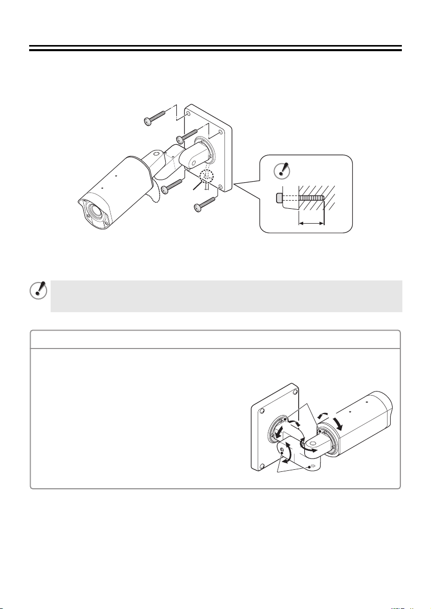
■ Installing the camera to the ceiling or wall
Use commercially-available screws (M8x4) to secure the camera base by the four screw holes (A).
(A)
(A)
(B)
(A)
(A)
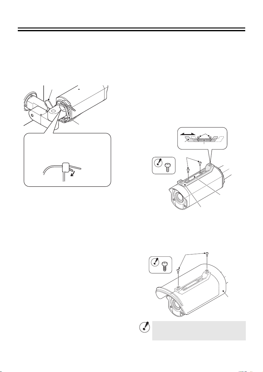
Note regarding cable hole in wall
When installing the camera base, check the position of the cable hole (B) and pull the cable through it.
Refer to page 7 for details on connecting the cable.
If the mounting screws are too short, the camera may fall down. When installing the camera, the
length (C) that the screw extends past the other side of the camera base should be 3 cm/1.2 in.
or more.
(C)
Adjusting the camera position and angle
Use the accessory hexagon wrench (large) to loosen the screws of the part you would like to move,
and then adjust so that the lens faces in the direction of monitoring within an angle of ±45 degrees.
1 If the camera is adjusted to an angle of ±45 degrees
or more, the cables will become twisted inside the
camera and they may break.
2 Adjustment is possible within a range of 180 degrees.
3 After adjusting the positions, tighten the screws to the
following torques.
A: 2 N·m or more (8 places)
B: 4.3 N·m or more (2 places)
(B)
(A)
1
1
2
3
Page 5
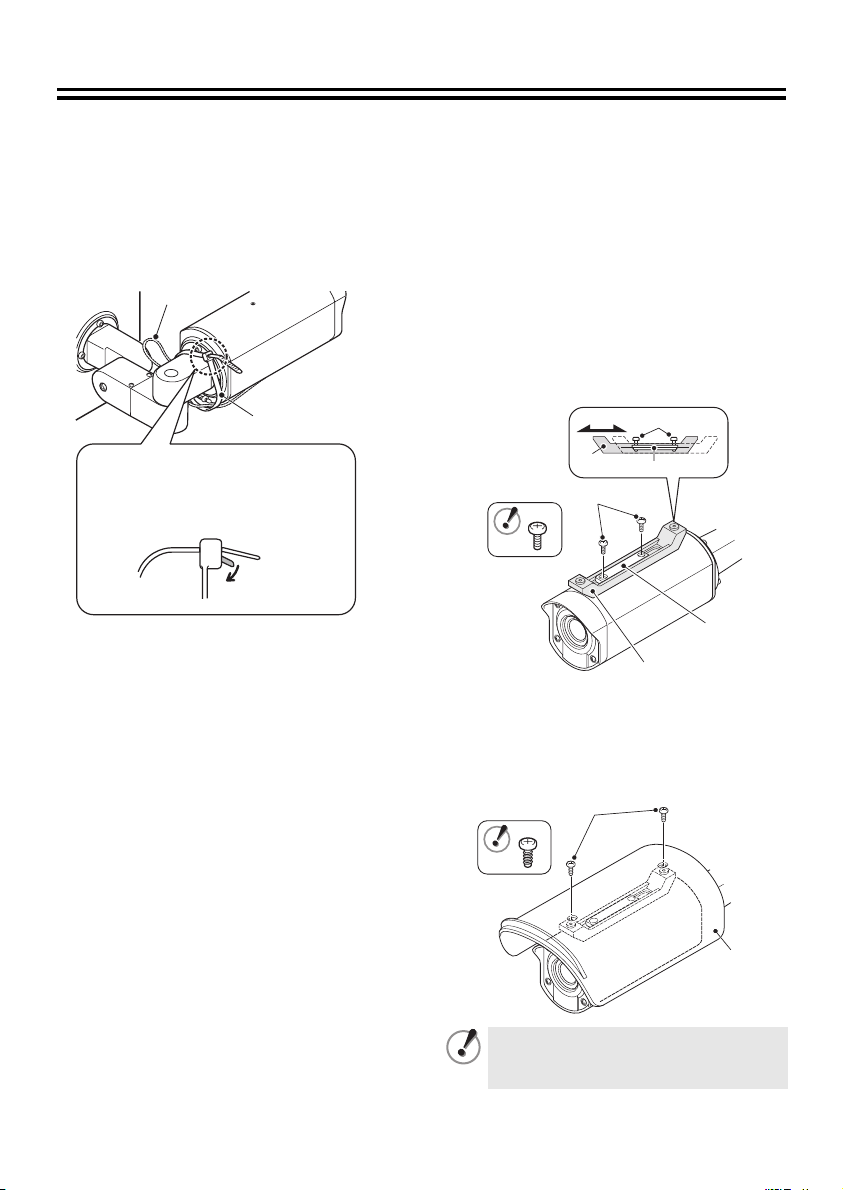
Use the following accessories if needed.
A Installing the fixing band
If you would like to secure the
drop-prevention chain (A) after installing and
adjusting the camera, secure it with the
accessory fixing band (B).
(A)
(B)
When temporarily removing the
fixing band after it has been
installed, push down the tab (C)
and then pull out the fixing band.
(C)
B Installing the sunshade
Align the sunshade adjustment
1
mounting bracket (A) with the mounting
surface, and then align it with the fixing
bracket (B) and provisionally secure it
with the accessory fixing screws (C).
Move the sunshade adjustment
2
mounting bracket (A) forward or back so
that the accessory sunshade (D) can be
installed, and then tighten the accessory
fixing screws (C).
(C)
(A)
Align the sunshade (D) with the screw
3
holes in the sunshade adjustment
mounting bracket (A), and then install it
by tightening the accessory sunshade
fixing tapping screws (E).
(B)
(C)
(A)
(E)
(B)
(D)
Tighten the screws (C) and the tapping
screws (E) at a torque of 0.5 N·m or
more.
4
Page 6
Checking the menus and zoom position using simple
monitor output
Fully loosen the four cover fixing screws
1
(A), and then pull the cover forward to
remove it.
• If only removing the camera cover (B),
partially loosen the cover fixing screws
(A).
• If removing the lens cover (C) too, fully
loosen the cover fixing screws (A).
The screw washers on the inside will
come loose. Be careful not to lose
them.
Use an alligator clip cable to connect the
2
MONITOR pin on the circuit board at the
bottom of the camera to the ground.
A dedicated MONITOR connector (D) is
provided for portable monitors.
1Checking and changing the menu
settings
2Checking and changing the zoom
position
• The optional camera control unit
(VAC-70) can be used to perform same
operations as the camera.
& See page 15.
B
C
GND
A
Install the camera cover, and then
3
tighten the four cover fixing screws (A)
evenly.
In order to maintain waterproof
performance, tighten the cover fixing
screws to the following torques.
A: 0.5 - 7 N·m (5 - 10 kgf·m)
MONITOR
D
(A)
5
Page 7
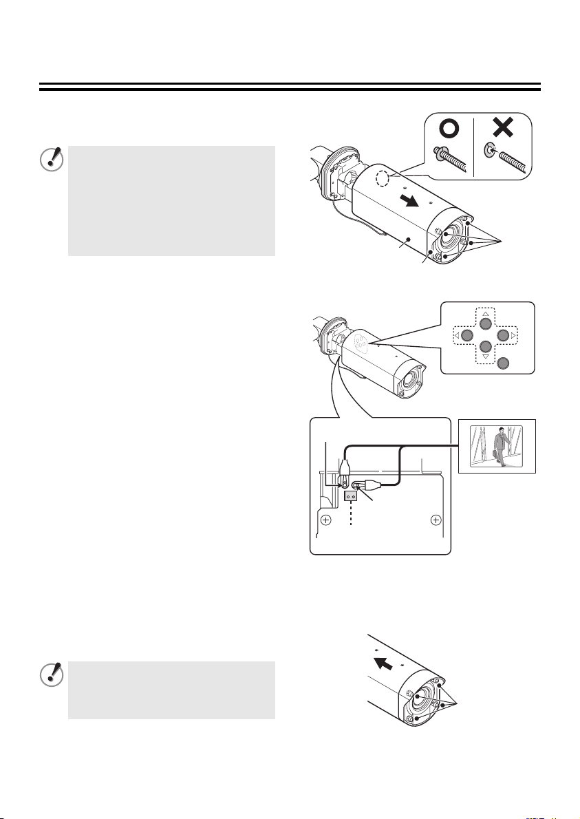
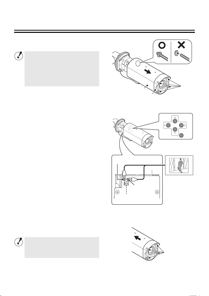
Desiccant for preventing humidity
Desiccant (blue: normal) has been placed inside the camera to prevent humidity. If the desiccant
has changed to a reddish-purple color, replace the desiccant with new desiccant before
installing the camera cover. If the camera is used without replacing the desiccant, condensation
may occur inside the camera and cause the lens to become foggy.
Replace the desiccant with the
3
accessory desiccant.
Install the camera unit (B) as shown in
4
the illustration, and then align the
camera fixing screw (A) with the screw
hole (D) in the camera unit and tighten
them.
(B)
(C)
■ Replacing the desiccant
Be sure to observe the following,
otherwise the camera may become
damaged.
• Be sure to turn off the power.
• Do not allow the camera to get wet
from rain water or other liquids.
Loosen the four cover fixing screws.
1
Refer to step 1 in “Checking the menus
and zoom position using simple monitor
output”. (P5)
Use the accessory hexagonal wrench
2
(small) to loosen the camera fixing
screw (A), and then remove the camera
unit (B) from the camera fixing bracket
(C).
(B)
(C)
(A)
(A)
(D)
• Tighten the camera fixing screw so
that the screw head (E) do not
protrude by any more than 0.5 mm/
0.02 in.
(E)
(F)
• When tightening the screws, the
camera fixing bracket (F) should be
horizontal.
Install the camera cover.
5
Refer to step 3 in “Checking the menus
and zoom position using simple monitor
output”. (P5)
6
Page 8
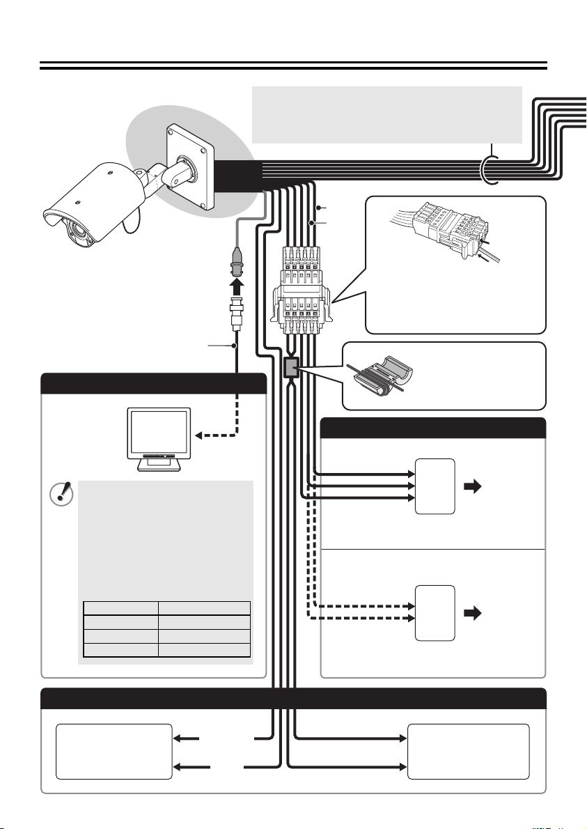
Connections 1
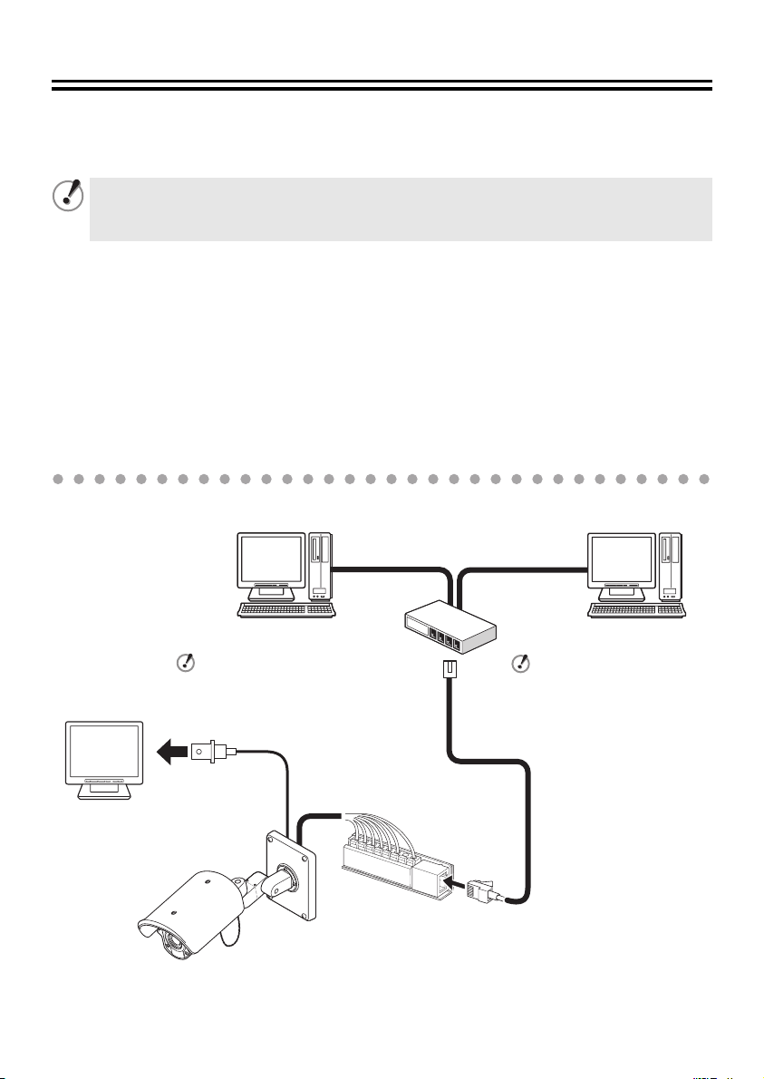
■ Connection when Using PoE (Power over Ethernet) Power Supply
This camera provides simultaneous delivery of video in the JPEG and H.264 formats and also
bi-directional video between the camera and PC.
● Do not use the power supply of the camera.
● Do not supply power to the PoE hub or PoE power adapter until the camera installation
is finished.
● System Requirements
The system requirements for camera operation via network are as follows:
•PC: IBM PC/AT and compatibles
•OS: Windows XP Home Edition/Windows XP Professional
•CPU: Pentium IV (2.0 GHz or higher) (3.0 GHz or higher for using the VA-SW3050Lite)
• Memory: 512MB or more (1 GB or more for using the VA-SW3050)
• Network interface: 10Base-T/100Base-TX (RJ-45 connector)
• Graphics processor: nVIDIA: GeForce 6000 series or higher
• Display card: 1024 x 768 pixels or higher, 16 million colors or higher
• Web browser: Internet Explorer Ver.6.0 or higher
Connect the camera to the LAN through a switching hub using shielded LAN cables.
When directly connecting
the camera to a PC, use
the LAN cable (cross
type).
TV monitor
ATI: RADEON X1000 series or higher
PC PC
When using the IE/VA-SW3050Lite/
VA-SW3050 client version:
You need a PC for the
VA-SW3050 server version.
LAN cable
(CAT5 or higher, straight type)
Max. 100 m/109 yds
LAN cable (CAT5 or
higher, straight type)
Max. 100 m/109 yds
Switching hub
When using the IE/VA-SW3050Lite/
VA-SW3050 server version:
You need the VA-SW3050
client version to view live/
replayed video, because the
VA-SW3050 server version is
used for recording purpose
only.
Video output
(BNC connector)
MEMO: You may extend the transmission distance by using multiple switching hubs with PoE support.
For details on the extendable distance, please refer to the hub performance in the
specifications, etc.
7
Page 9
VCC-XZN600P
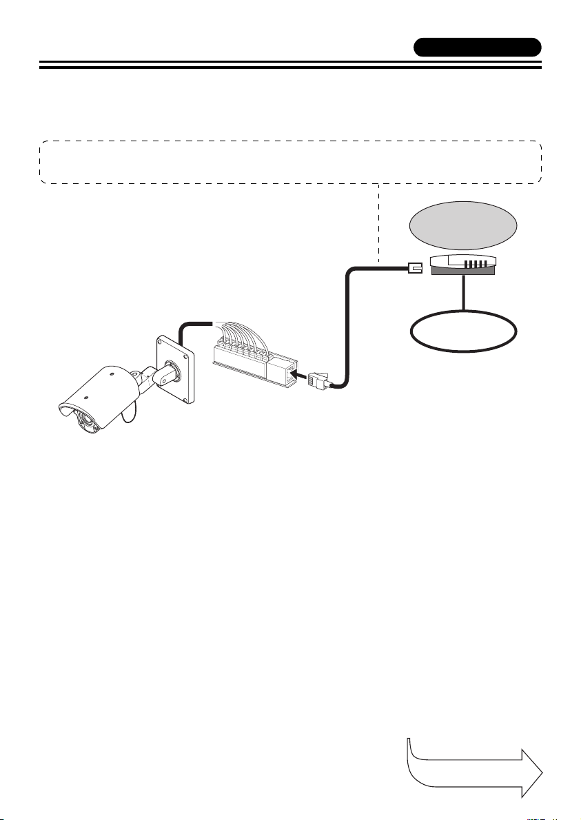
■ Connection when Not Using PoE Power Supply
● Internet connection
Connect the camera to a router or ADSL modem with LAN interface using shielded LAN cables.
When connecting to a router, use the straight type LAN cable (CAT5 or higher).
When connecting to an ADSL modem or other devices, refer to the instruction manual for the device.
Router or
ADSL modem
Internet
● About the internet connection
Port forwarding must be set on two of the router ports (camera side).
For details on how to set port forwarding, please refer to your router's instruction manual.
• Video port number
Conduct the following port forwarding settings with respect to the router:
IP address on the LAN side: Camera IP address (default: 192.168.0.2)
Port number on the LAN side: Camera video port number (default: 80)
Port number on the WAN side: Optional
For communication, use TCP/IP.
MEMO: When viewing video in H.264 format over the Internet, set the communication protocol of H.264
to "HTTP". (Refer to the instruction manual contained in the supplied CD-ROM.)
Continued to the
next page.
8
Page 10

Connections 1
BNC type
Note:
All connection cables should be 24 AWG or
higher with a maximum length of no more than
600 m (656 yds).
Shielded LAN cable
(CAT5 or higher, straight type)
See “Connection when Using PoE
Power Supply” or “Connection when
Not Using PoE Power Supply”.
Coaxial cable
Digital video recorder etc.
Monitor Connection
• Using different cables from
those specified here may
attenuate the video and/or sync
signals and interfere with
correct transmission.
• RG-59U coaxial cables can be
used when distance between
devices is short, but not in duct
or aerial routing.
Cable type Length
RG-59U (3C-2V) 250 m (273 yds) max.
RG-6U (5C-2V) 500 m (547 yds) max.
RG-11U (7C-2V) 600 m (656 yds) max.
RED
WHITE
1 Push and hold the lever a, and
then insert the cable into the
terminal hole
2 Release the lever
B.
A.
Power Supply Connection
b With AC 24 V
✱
b With DC 12 V
Check that +/- polarity is correct.
✱
~
~
GND
(+)
(–)
A
B
✱ For the connections, use AWG (20, 21, 22)
cables.
9
Page 11
VCC-XZN600P
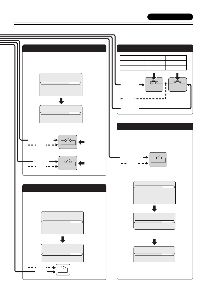
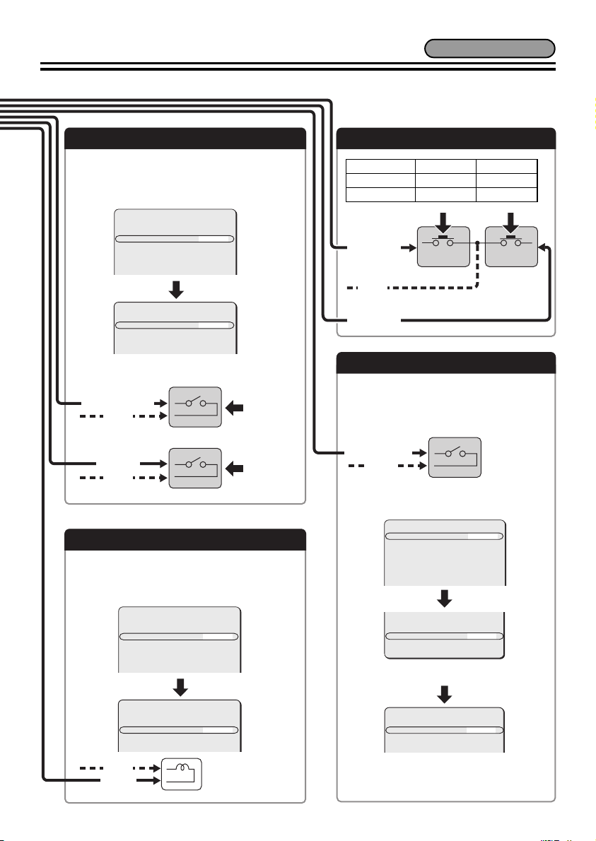
Alarm Signal Input
For details, see “Setting the Alarm Input
(ALARM IN)” in the electronic manual contained
in the CD-ROM.
SYNC
CAMERA
LENS
ALARM
PRIVACY MASK
PASSWORD
LANGUAGE
OPTION
ALARM IN
ALARM OUT
ALARM DISPLAY
ALARM
INT
1
SET
SET
SET
SET
SET
SET
1
SET
OFF
y
y
y
y
y
y
y
y
y
b ALARM IN 1 (“1” is selected)
(GRAY/BLACK)
(GND)
Alarm
input signal
b ALARM IN 2 (“2” is selected)
(BLACK)
(GND)
Alarm
input signal
Alarm Signal Output
If a lamp is connected to this cable, it will light
up when an alarm signal is received or when
the built-in motion sensor detects movement.
Connection for Zoom/Focus
DC+6V/+12V FAR WI DE
DC-6V/-12V NEAR TELE
(YELLOW)
(GND)
(ORANGE)
Color or Black-and-White Settings
The alarm input terminals can also be
used as terminals for switching between
color and black/white video modes using
an external switch.
(GRAY/BLACK
or BLACK)
(GND)
FOCUS ZOOM
Open: Color
Close: Black/White
SYNC
CAMERA
LENS
ALARM
PRIVACY MASK
PASSWORD
LANGUAGE
OPTION
INT
1
SET
SET
SET
SET
SET
SET
y
y
y
y
y
y
y
SYNC
CAMERA
LENS
ALARM
PRIVACY MASK
PASSWORD
LANGUAGE
OPTION
ALARM IN
ALARM OUT
ALARM DISPLAY
(GND)
(BLUE)
ALARM
INT
1
SET
SET
SET
SET
SET
SET
1
SET
OFF
GAMMA
y
y
y
y
y
y
y
y
y
MOTION
POSITION
DAY/NIGHT
PRESET
MENU
Make sure that COLOR is
selected.
D/N SETTING-COLOR
EXT ALARM
0.45
OFF
OFF
COLOR
OFF
BACK
1
y
1: ALARM IN 1 terminal
2: ALARM IN 2 terminal
10
Page 12
Connections 2
Note:
All connection cables should be 24 AWG or
higher with a maximum length of no more than
600 m (656 yds).
RED
WHITE
1,3
BNC type
Coaxial cable
Monitor Connection
• Using different cables from
those specified here may
attenuate the video and/or sync
signals and interfere with
correct transmission.
• RG-59U coaxial cables can be
used when distance between
devices is short, but not in duct
or aerial routing.
Cable type Length
RG-59U (3C-2V) 250 m (273 yds) max.
RG-6U (5C-2V) 500 m (547 yds) max.
RG-11U (7C-2V) 600 m (656 yds) max.
1 Push the lever.
2 Insert the cable into the
terminal hole.
3 Release the lever.
To prevent
electromagnetic
interference
(Installation accessories)
Power Supply Connection
b With AC 24 V
~
~
GND
For the connections, use cables thicker
than 18 AWG.
b With DC 12 V
Check that +/- polarity is correct.
(+)
(–)
For the connections, use cables thicker
than 18 AWG.
2
Connection with a communication device for remote operation
UTP
Receiver Controller
(+)
(–)
UTP
(SKYBLUE)
(PINK)
RS485 (A)
RS485 (B)
11
Page 13
VCC-XZ600P
Alarm Signal Input
For details, see “Setting the Alarm Input
(ALARM IN)” in the electronic manual contained
in the CD-ROM.
SYNC
CAMERA
LENS
ALARM
PRIVACY MASK
PASSWORD
LANGUAGE
OPTION
ALARM IN
ALARM OUT
ALARM DISPLAY
ALARM
INT
1
SET
SET
SET
SET
SET
SET
1
SET
OFF
y
y
y
y
y
y
y
y
y
b ALARM IN 1 (“1” is selected)
(GRAY/BLACK)
(GND)
Alarm
input signal
b ALARM IN 2 (“2” is selected)
(BLACK)
(GND)
Alarm
input signal
Alarm Signal Output
If a lamp is connected to this cable, it will light
up when an alarm signal is received or when
the built-in motion sensor detects movement.
Connection for Zoom/Focus
DC+6V/+12V FAR WI DE
DC-6V/-12V NEAR TELE
(YELLOW)
(GND)
(ORANGE)
Color or Black-and-White Settings
The alarm input terminals can also be
used as terminals for switching between
color and black/white video modes using
an external switch.
(GRAY/BLACK
or BLACK)
(GND)
FOCUS ZOOM
Open: Color
Close: Black/White
SYNC
CAMERA
LENS
ALARM
PRIVACY MASK
PASSWORD
LANGUAGE
OPTION
INT
1
SET
SET
SET
SET
SET
SET
y
y
y
y
y
y
y
SYNC
CAMERA
LENS
ALARM
PRIVACY MASK
PASSWORD
LANGUAGE
OPTION
ALARM IN
ALARM OUT
ALARM DISPLAY
(GND)
(BLUE)
ALARM
INT
1
SET
SET
SET
SET
SET
SET
1
SET
OFF
GAMMA
y
y
y
y
y
y
y
y
y
MOTION
POSITION
DAY/NIGHT
PRESET
MENU
Make sure that COLOR is
selected.
D/N SETTING-COLOR
EXT ALARM
0.45
OFF
OFF
COLOR
OFF
BACK
1
y
1: ALARM IN 1 terminal
2: ALARM IN 2 terminal
12
Page 14
Features
POSIT ION
x 3.0
POSIT ION
DOOR1
& You can perform the settings on the camera by
navigating through the menu screens.
Zooming Function
b You can store the zoom and focus
settings of surveillance locations by
camera setting number.
& [CAMERA] ⇒ [POSITION]
CAMERA 1 CAMERA 2
POSITION
x 1.0
POSITION
SET
y
x 3.0
x 3.0
POSITION
POSITION
SET
y
b The electronic zooming function can be
used to zoom in the object at the
magnification power higher than that in
the optical zoom.
& [LENS] ⇒ [ZOOM] ⇒ [EL ZOOM]
b You can change the zooming speed.
& [LENS] ⇒ [ZOOM] ⇒ [SPEED]
Remote Operations
VCC-XZN600P
b
The camera can be controlled remotely
by establishing the network
communication.
& [OPTION] ⇒ [NETWORK]
VCC-XZ600P
b
The camera can be controlled remotely
by establishing the RS-485 or coaxial
super imposed communication.
& [OPTION] ⇒ [SYSTEM]
b You can switch the viewing mode
manually between the color mode and
the black/white mode.
& [CAMERA] ⇒ [COLOR] ⇒
[EXT ALARM]
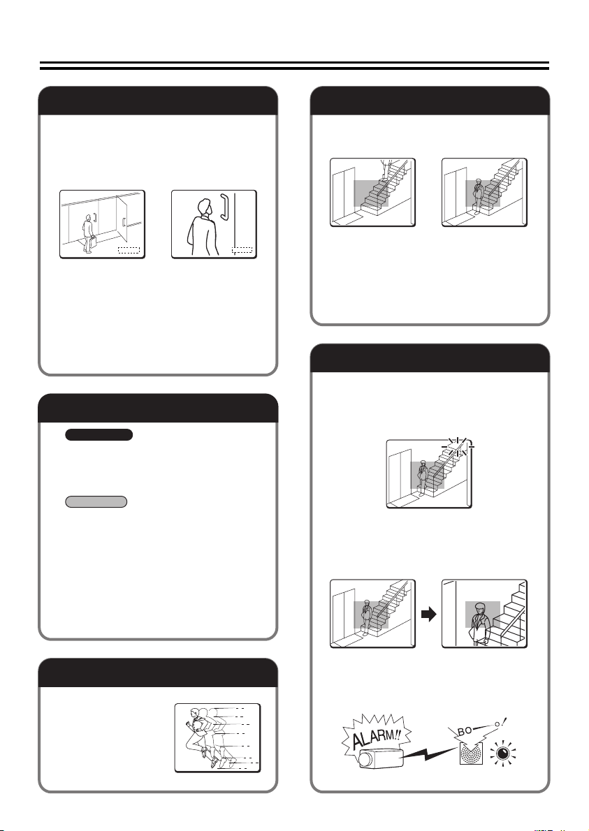
Alarm Settings
b The camera has a built-in motion sensor.
& [CAMERA] ⇒ [MOTION] ⇒ [ON]
Not detected Detected
b The alarm condition can be detected by
connecting door switches or infrared
sensors.
& [ALARM] ⇒ [ALARM IN]
Alarm Notice
b The camera title you specified in the
[OPTION] menu blinks to notify that the
alarm condition is detected.
& [ALARM] ⇒ [ALARM DISPLAY]
DOOR1
DOOR1
b When the alarm condition is detected,
the object on the screen is zoomed in.
& [ALARM] ⇒ [ALARM IN] ⇒
[ACTION] ⇒ [ZOOM]
Shutter Speed Settings
The camera can
monitor a
fast-moving object.
& [CAMERA] ⇒
[SHUTTER]
b A buzzer or lamp can be used to notify
you of detection of alarm when you are in
a distant place from the monitor.
& [ALARM] ⇒ [ALARM OUT]
13
Page 15
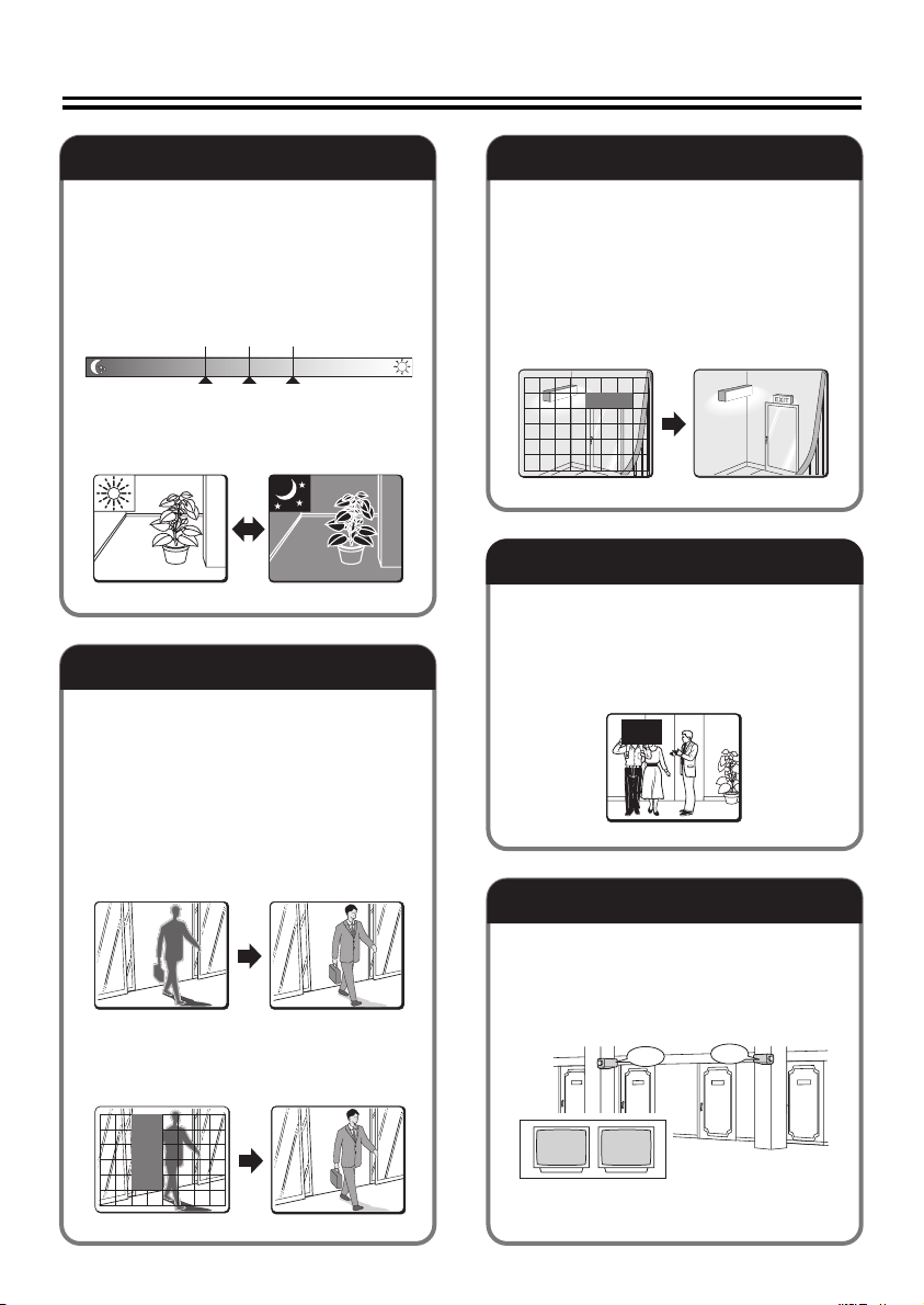
Day/Night Function
B/W
Color
White Balance Adjustment
According to the luminance level, the
viewing mode will be switched
automatically between the color mode
and the black/white mode.
You can adjust the luminance threshold
for switching the viewing mode.
LOW MID HIGH
B/W
B/W Color
Switchover point
Color
& [CAMERA] ⇒ [DAY/NIGHT] ⇒
[AUTO] ⇒ [LEVEL]
Backlight Compensation
b The camera uses 48-part split
metering areas to compensate the
backlight condition by metering each
area.
You can also select 5-part split
metering areas (center, left, right, top
and bottom) for metering.
& [CAMERA] ⇒ [BLC] ⇒ [MULT] or
[CENT]
In addition to the white balance
adjustment, you can use the mask
patterns to cover extremely bright or
dark light source in the monitored image
so that the white balance adjustment is
properly configured.
& [CAMERA] ⇒ [WHITE BALANCE] ⇒
[ATW] ⇒ [MASKING]
Privacy Masks
The privacy masks can be used to
protect privacy by hiding certain part of
the monitored image.
(Maximum 4 masks)
& [PRIVACY MASK]
Camera Title
b You can mask a metering area you do
not want to meter.
& [CAMERA] ⇒ [BLC] ⇒ [MASK]
You can set and display the camera title.
This helps you confirm from which camera
the image is sent when multiple cameras
are connected. (Maximum 16 characters)
& [OPTION] ⇒ [DISPLAY] ⇒ [TITLE]
ROOM1
ROOM1 ROOM2
ROOM2
14
Page 16
How to Perform the Settings in the Menu Screens
This manual and the electronic manual which is contained in the supplied CD-ROM
describe the operations using the buttons on the camera.
The optional camera control unit (VAC-70) can be used to perform same operations as the
camera.
For details, refer to the instruction manual for the camera control unit.
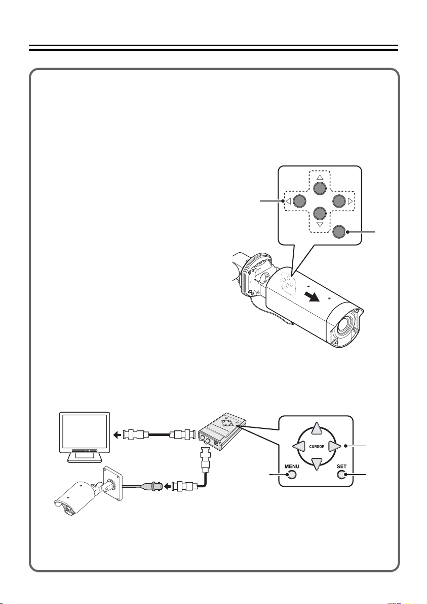
A Using the buttons on the camera
1 Displays the main menu.
Press and hold down the SET
button for 3 seconds or longer to
display the main menu.
2 Moves the cursor during menu
setting operations.
3 Switches the menu screen.
4 Performs focusing or zooming
in/out operations.
While the auto-focus function is
activated, you can perform
focusing operations using the
buttons.
j: NEAR l: FAR
d: WIDE c: TELE
2
4
1
3
B Using the VAC-70 camera control unit (optionally available) to perform
the settings remotely
VAC -7 0
Video in
• Be sure to disconnect the camera control unit after you complete setting up the camera.
• Avoid connecting the camera control unit via a cable compensator or video distribution
amplifier.
Doing so may prevent remote control of your camera.
VIDEO OUT
CAMERA
BNC type
1
2
4
3
15
Page 17
Learning the Menu Setting Operations
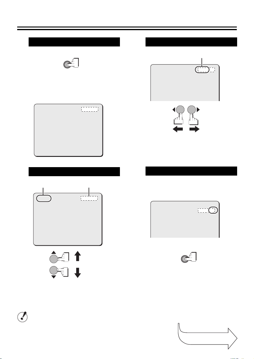
1
2
Display the main menu.
SET
Press and hold the button for
about 3 seconds.
<Main menu>
SYNC
CAMERA
LENS
ALARM
PRIVACY MASK
PASSWORD
LANGUAGE
OPTION
PRESET
MENU
INT
1
SET
SET
SET
SET
SET
SET
OFF
END
Select a menu item.
CursorMenu item
SYNC
CAMERA
LENS
ALARM
PRIVACY MASK
PASSWORD
LANGUAGE
OPTION
PRESET
MENU
INT
1
SET
SET
SET
SET
SET
SET
OFF
END
3
Select a setting value.
Setting value
SYNC
CAMERA
LENS
ALARM
PRIVACY MASK
PASSWORD
LANGUAGE
OPTION
y
y
y
y
y
y
y
Pressing the dc button
INT
1
SET
SET
SET
SET
SET
SET
y
y
y
y
y
y
y
switches the setting
values.
4
Go to the next screen.
When you select the menu item with y mark
and press the SET button, the submenu
screen for advanced options appears.
y
y
y
y
y
y
y
SYNC
CAMERA
LENS
ALARM
PRIVACY MASK
PASSWORD
LANGUAGE
OPTION
INT
1
SET
SET
SET
SET
SET
SET
y
y
y
y
y
y
y
SET
Pressing the jl button
moves the cursor.
After the expiration of a predetermined time interval (3 minutes) without any operation, the
menu screen goes off automatically.
Continued to the
next page.
16
Page 18
Learning the Menu Setting Operations
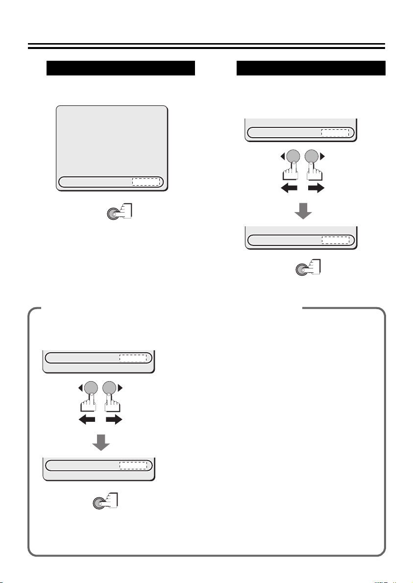
Return to the previous screen.
5
Select [MENU] – “BACK” at the bottom of the
screen, and press the SET button.
6
Select [MENU] – “BACK” at the bottom of the
screen, use the dc button to select “END”,
Exit from the menu screen.
and press the SET button.
IRIS
WHITE BALANCE
BLC
SHUTTER
APERTURE
AGC
GAMMA
MOTION
POSITION
DAY/NIGHT
PRESET
MENU
SET
AUTO
ATW
OFF
OFF
ON
ON
0.45
OFF
OFF
AUTO
OFF
BACK
y
y
y
y
y
PRESET
MENU
PRESET
MENU
Restoring the default values (factory settings)
● Restoring the default values only for the current
screen
PRESET
MENU
PRESET
MENU
SET
OFF
BACK
ON
END
Select “ON” for [PRESET] and press the SET button.
● Restoring all the default values on the camera
In the main menu, select “ON” for [PRESET] and press
the SET button.
Note that the resetting operation does not reset the
settings for the following items:
• [PRIVACY MASK] on main menu
• [PASSWORD] on the main menu
• [DISPLAY (TITLE)] and [SYSTEM] on the OPTION
menu
• Zoom or focus setting in [POSITION] on the CAMERA
menu
Note that the value of the item [POSITION] is reset
from “ON” to the default “OFF”.
When the [POSITION] setting is switched to “OFF”,
the zoom and focus settings stored in the camera will
be overwritten by those settings of the current
position.
In the same way, performing zoom or focus operation
with [POSITION] set to “OFF” also overwrites the
stored zoom and focus settings.
SET
OFF
BACK
OFF
END
17
Page 19
Using the Electronic Manual (CD-ROM)
The menu screens enable you to easily perform setting and adjustment of this camera.
By using the electronic manual which is contained in the supplied CD-ROM, you can access
extensive information from basic operation to advanced settings and functions, as well as
troubleshooting.
Requirements for viewing the electronic manual
Browser: Internet Explorer 6.0 or higher
• Make sure that JavaScript and Cookie are enabled.
• To use the Search function, also enable the ActiveX control.
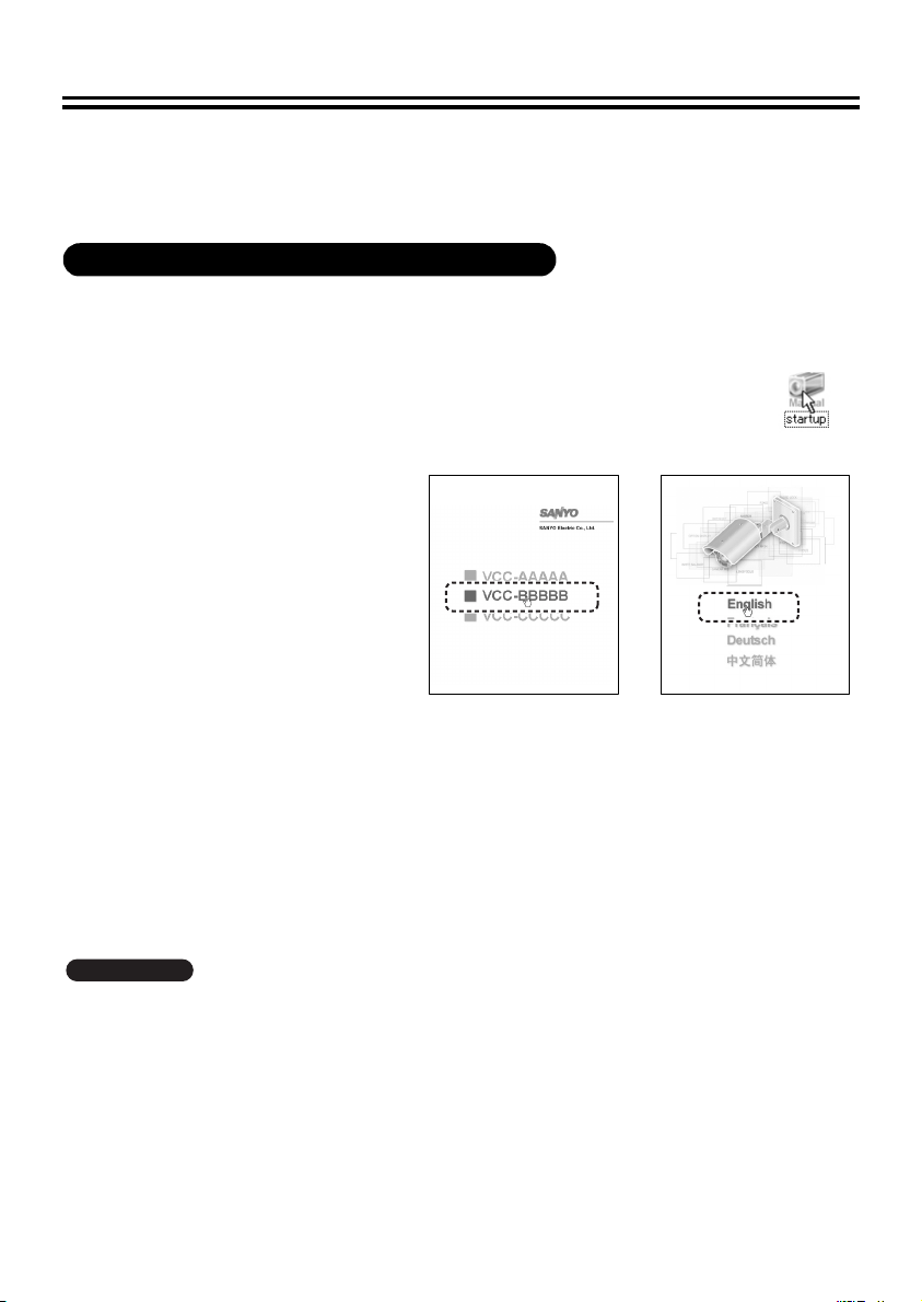
Insert the CD-ROM into the CD drive of your computer and then double-click the “ ”
1
icon.
Select the model of the camera
2
(Screen 1).
Select the preferred language
3
(Screen 2).
The electronic manual opens.
Click “Open this manual”.
4
From the menu located on the left of the
screen, click an item on which you want
to get relevant information.
An applicable page will open.
(Screen 2)(Screen 1)
• Viewing menu setting procedures for each usage
Click “Guide to the Setting Menu” on the menu located on the left of the screen.
• Viewing definitions of glossary
Click “Glossary” on the menu located on the left of the screen.
• Viewing troubleshooting procedure
Click “Troubleshooting” on the menu located on the left of the screen.
& You can also refer to “How to use this manual” to better understand the structure of the
electronic manual and the description of individual screens.
VCC-XZN600P
To open and view the instruction manual (VA-SW3050Lite), you need Adobe Reader installed on your
PC.
If it has not been installed on your PC, visit the Adobe website at http://www.adobe.com to download
and install the free software program.
18
Page 20

Main specifications 1
■ Camera
Television system PAL color standards
Image sensor 1/4" interline transfer CCD
Effective pixels 752 (Horizontal) x 582 (Vertical)
Scanning system 2:1 interlaced, 625 lines
Synchronization method Internal synchronization/Line lock (with vertical phase adjustment)
Video output 1.0 V (p-p)/75Ω, BNC connector
Horizontal resolution 540 TV lines, typical
Lowest image illumination 0.8 lx (at F1.4, color mode, Gain: High)
Video S/N ratio 50 dB or more (AGC OFF)
Lens Motorized zoom (x30 optical zoom)
Electronic zoom Max. x16 (combined with optical zoom gives max. x480)
Alarm input Control terminal x 2, NO (Normal Open) or NC (Normal Close)
Alarm output Control terminal x 1, NO/NC switching, open collector
Focus/Zoom control Control voltage: ± (6 - 12) V DC
Waterproof standard IP66
Network LAN terminal (RJ-45 terminal), 10 Base-T/100 Base-TX
Operating ambient
temperature/humidity
Power source
Power consumption 7.3 W
Weight With sunshade: Approx. 2.0 kg/65 oz.
0.04 lx (at F1.4, B/W mode, Gain: High)
Auto-Focus, auto iris lens, f=3.5 - 105 mm (F1.4 - 3.7)
Also used for Day/Night switching.
-10 - +50°C/14 - 122°F, 90% RH max. (no condensation)
With power source connected: -20 - +50°C/-4 - +122°F
• 24 V AC ± 10%, 50 Hz
• 12 - 15 V DC
• Supplied through PoE (compliant with IEEE802.3af)
Without sunshade: Approx. 1.8 kg/58 oz.
VCC-XZN600P
■ Network
Image compression JPEG/H.264 (simultaneous transmission available)
Resolution JPEG: 720×288, 640×480, 360×288, 176×144, 720×576
Picture quality 5 levels
Frame rate JPEG: Max 25ips (720×576)
Bandwidth 128, 256, 512 Kbps, 1, 2, 3, 4 Mbps, no limitation
Alarm buffer Up to 8 MB; configurable
Interface Ethernet 10BASE-T/100BASE-TX (RJ45 connector)
Communication method TCP/IP, UDP, HTTP, HTTPS, SMTP, NTP, DHCP, FTP, UPnP, DDNS
Simultaneous access
capacity
Security BASIC authentication (ID/password), SSL supported
Operating temperature -10°C - +50°C/14°F - 122°F
H.264: Main Profile, Level 3
H.264: 720×576, 352×288, 176×144
H.264: Max 25ips (720×576)
Maximum 16 users (admin: 1 user)
Maximum 12 users (admin: 1 user, SSL ON)
19
Page 21

Main specifications 2
Television system PAL color standards
Image sensor 1/4" interline transfer CCD
Effective pixels 752 (Horizontal) x 582 (Vertical)
Scanning system 2:1 interlaced, 625 lines
Synchronization method Internal synchronization/Line lock (with vertical phase adjustment)
Video output 1.0 V (p-p)/75Ω, BNC connector
Horizontal resolution 540 TV lines, typical
Lowest image illumination 0.8 lx (at F1.4, color mode, Gain: High)
Video S/N ratio 50 dB or more (AGC OFF)
Lens Motorized zoom (x30 optical zoom)
Electronic zoom Max. x16 (combined with optical zoom gives max. x480)
Alarm input Control terminal x 2, NO (Normal Open) or NC (Normal Close)
Alarm output Control terminal x 1, NO/NC switching, open collector
Focus/Zoom control Control voltage: ± (6 - 12 V) DC
Waterproof standard IP66
Communication method System connection terminals (RS-485/Coaxial, UTP (NVT built-in), support of camera control
Operating ambient
temperature/humidity
Power source
Power consumption 4.9 W
Weight With sunshade: Approx. 2.0 kg/65 oz.
0.04 lx (at F1.4, B/W mode, Gain: High)
Auto-Focus, auto iris lens, f=3.5 - 105 mm (F1.4 - 3.7)
Also used for Day/Night switching.
unit (VAC-70))
-10 - +50°C/14 - +122°F, 90% RH max. (no condensation)
With power source connected: -20 - +50°C/-4 - +122°F
• 24 V AC ± 10%, 50 Hz
• 12 - 15 V DC
Without sunshade: Approx. 1.8 kg/58 oz.
VCC-XZ600P
20
Page 22

● License for Software Contained in CD-ROM
• Please read carefully the terms and conditions contained in the license agreement that appears on
the screen during the software installation process. Provided that you have agreed to all the terms
and conditions therein, you may use the software subject to the license agreement.
• For information on the other products or services provided by third parties which are introduced in the
CD-ROM, please contact each supplier or manufacturer.
Microsoft, Windows, ActiveX and Internet Explorer are registered trademarks or trademarks of Microsoft
Corporation in the United States and other countries.
The official name for “Windows” used in this manual is Microsoft
manual, note that the word “Windows” is used for referring to “Microsoft
System”.
Intel and Pentium are registered trademarks or trademarks of Intel Corporation and its subsidiaries in
the United States and other countries.
IBM and IBM PC/AT are trademarks of International Business Machines Corporation.
Adobe Reader is a trademark of Adobe Systems Incorporated.
UPnP is a trademark of UPnP Implementers Corporation, which is established by the UPnP Forum SC.
Java is a trademark of Sun Microsystems, Inc.
All other brands and product names in this manual are the registered trademarks or trademarks of their
respective owners.
®
Windows® Operating System. In this
®
Windows® XP Operating
21
Page 23
MANUEL D’INSTALLATION
Caméra CCD couleurs
CETTE INSTALLATION DOIT ETRE EFFECTUEE PAR UNE
PERSONNE QUALIFIEE DU SERVICE TECHNIQUE ET DOIT
ETRE CONFORME A TOUS LES CODES LOCAUX.
VCC-XZN600P
VCC-XZ600P
Veuillez lire ce manuel d’installation très attentivement afin d’effectuer une installation correcte.
Veuillez également lire très attentivement le manuel électronique contenu dans le CD-ROM afin
de faire fonctionner la caméra correctement.
Exemples d’installation
(Installation au plafond)
(Installation au mur)
Table des matières
Informations pour l’utilisateur . . . . . . . . . . . 1
Méthode d’installation . . . . . . . . . . . . . . . . . 3
Vérification des menus et de la position de
zoom avec une sortie d’écran simple . . . . . 5
Dessiccatif de prévention de l’humidité . . . 6
Branchements 1 . . . . . . . . . . 7
Branchements 2 . . . . . . . . . . 11
Caractéristiques . . . . . . . . . . . . . . . . . . . . . 13
Comment effectuer les réglages dans les
écrans de menu. . . . . . . . . . . . . . . . . . . . . . 15
Apprentissage des opérations de réglage
menu. . . . . . . . . . . . . . . . . . . . . . . . . . . . . . . 16
Utilisation du manuel électronique
(CD-ROM) . . . . . . . . . . . . . . . . . . . . . . . . . . . 18
Spécifications principales 1
Spécifications principales 2
& Inclus à la fin de cette brochure
• Pattern sheet (Modèle)
• Accessoires
Dimensions . . . . . . . . . . . . . . . . . . Page verso
VCC-XZN600P
VCC-XZ600P
VCC-XZN600P
VCC-XZ600P
. . 19
. . . 20
EnglishFrançaisDeutsch中文简体
N.B.:
Le présent manuel d’installation couvre deux
modèles. Les éventuelles différences entre les
deux modèles sont indiquées quand cela est
nécessaire.
Page 24
Informations pour l’utilisateur
Veuillez respecter les
instructions suivantes
• Faites très attention au cours des opérations
telles que le perçage de trous pour installer
cette attention. Faites également ressortir les
câbles d’alimentation et vidéo par exemple, il
sera ainsi plus facile de les acheminer.
• Lorsque vous installez la caméra, prendre
toutes les précautions nécessaires pour vous
assurer que le plafond ou le mur soit bien
étanche.
• Choisissez un plafond ou un mur plat, durable
et en mesure de supporter le poids de la
caméra. Si vous l’installez sur une surface
courbée, ronde ou autre, utilisez alors un
support de montage en vente dans le
commerce.
• Installez la caméra dans un endroit où la
température ambiante (avéc source
d’alimentation connectée) est comprise entre
-20°C et 50°C (à laquelle la condensation ne
devrait pas se former).
• Si la caméra est soumise aux rayons directs
du soleil, installez le pare-soleil fourni.
Précautions
■ En cas de problème
N’utilisez pas l’appareil si de la fumée ou une odeur
étrange s’en dégage, ou s’il semble ne pas
fonctionner correctement. Éteignez l’appareil
immédiatement et débranchez le cordon
d’alimentation, puis adressez-vous à votre
revendeur ou à un Centre de service Sanyo
autorisé.
■ Ne l’ouvrez pas et ne le modifiez pas
N’ouvrez pas le boîtier, car cela peut être dangereux
et risque de causer des dommages à l’appareil.
Pour les réglages internes et les réparations,
adressez-vous à votre revendeur ou à un Centre de
service Sanyo autorisé.
■ Ne mettez pas d’objets dans l’appareil
Assurez-vous qu’aucun objet métallique ou
inflammable n’entre dans l’appareil. S’il est utilisé
avec un objet étranger à l’intérieur, cela risque de
causer un incendie, des courts-circuits ou des
dommages. Faites attention pour protéger l’appareil
de la pluie, de l’eau de mer, etc. Si de l’eau ou autre
liquide entre dans l’appareil, éteignez l’appareil
immédiatement et débranchez le cordon
d’alimentation, puis adressez-vous à votre
revendeur ou à un Centre de service Sanyo
autorisé.
■ Faites attention lors de la manipulation de
l’appareil
Pour éviter de l’endommager, ne laissez pas tomber
l’appareil ou ne le soumettez pas à des chocs ou à
des vibrations.
■ N’installez pas l’appareil près de champs
magnétiques
Les champs magnétiques peuvent causer un
mauvais fonctionnement.
■ Gardez-le à l’abri de l’humidité et de la
poussière
Pour éviter d’endommager l’appareil, ne l’installez
pas là où il y a de la vapeur ou de la fumée grasse,
où le degré d’humidité risque de devenir trop élevé
ou là où il y a beaucoup de poussière.
■ Gardez-le à l’abri des températures élevées
N’installez pas l’appareil près de fours, ou autres
appareils qui émettent de la chaleur, comme des
projecteurs, etc., ou là où il peut être sujet aux
rayons directs du soleil, car cela peut causer une
déformation, décoloration ou autres dommages.
Faites attention lors de l’installation près du plafond,
dans une cuisine ou dans une chambre des
machines, car la température risque de monter à un
niveau élevé.
■ Nettoyage
• La poussière peut être retirée du boîtier en
l’essuyant à l’aide d’un chiffon doux. Pour retirer
les taches, essuyez à l’aide d’un chiffon doux
humecté d’une solution de détergent doux et bien
essoré, puis séchez à l’aide d’un chiffon doux et
sec.
• N’utilisez pas de solvants, dissolvant ou autres
produits chimiques sur le boîtier, car cela risque
de causer une déformation et un écaillage de la
peinture. Avant d’utiliser un chiffon traité
chimiquement, assurez-vous de lire toutes les
instructions qui l’accompagnent. Assurez-vous
qu’aucune pièce en plastique ou caoutchouc ne
soit en contact avec le boîtier pendant une
longue période, car cela risque de causer des
dommages ou un écaillage de la peinture.
■ Approbations: IP66/CE
Cet appareil a été certifié selon les standards IP66
lorsque correctement installé.
N’utilisez qu’un coffret ou un boîtier électrique
certifié IP66.
Assurez-vous que toutes les ouvertures du coffret
sont scellées selon les instructions du fabricant.
1
Page 25
Pour Utilisateurs de l’UE
Svp note:
Votre produit Sanyo est conçu et
fabriqué avec des matèriels et des
composants de qualité supérieure qui
peuvent être recyclés et réutilisés.
Ce symbole signifie que les
équipements électriques et
électroniques en fin de vie doivent être
éliminés séparément des ordures
ménagères.
Nous vous prions donc de confier cet
équipement à votre centre local de
collecte/recyclage.
Dans l’Union Européenne, il existe des
systèmes sélectifs de collecte pour les
produits électriques et électroniques
usagés.
Aidez-nous à conserver
l’environnement dans lequel nous
vivons !
Les machines ou appareils électriques
et électroniques contiennent
fréquemment des matières qui, si elles
sont traitées ou éliminées de manière
inappropriée, peuvent s’avérer
potentiellement dangereuses pour la
santé humaine et pour l’environnement.
Cependant, ces matières sont
nécessaires au bon fonctionnement de
votre appareil ou de votre machine.
Pour cette raison, il vous est demandé
de ne pas vous débarrasser de votre
appareil ou machine usagé avec vos
ordures ménagères.
Ce symbole et le système de
recyclage ne sont appliqués que
dans les pays UE et non dans
les autres pays du monde.
SANYO FISHER Sales (Europe) GmbH
Stahlgruberring 4, D-81829 München, Germany
SANYO Electric Co., Ltd.
1-1, Sanyo-cho, Daito City, Osaka 574-8534, Japan
Le manuel d’installation et le manuel électronique sont protégés par les droits d’auteur de SANYO
Electric Co., Ltd.
Aucun des éléments contenus dans ces manuels ne peut être reproduit, sous quelque format que ce
soit, sans l’autorisation préalable du détenteur du copyright.
2
Page 26
Méthode d’installation
■ Installation de la caméra au plafond ou au mur
À l’aide de vis (M8x4) en vente dans le commerce, fixez l’embase de la caméra au niveau des quatre
trous de vis (A).
(A)
(A)
(B)
(A)
(A)
Remarque concernant le trou de passage du câble au mur
Lorsque vous montez l’embase de la caméra, vérifiez la position du trou de câble (B), puis faites-y
glisser le câble. Référez-vous à la page 5 pour plus d’informations concernant le branchement du câble.
Si les vis de montage sont trop courtes, la caméra risque de tomber. Lorsque vous installez la
caméra, la partie (C) du pas de vis qui dépasse de l’autre côté de l’embase doit être longue d’au
moins 3 cm.
(C)
Réglage de la position et de l’angle de la caméra
Utilisez la clé hexagonale fournie (la grande) pour desserrer les vis de la partie que vous désirez
déplacer, puis réglez-les de manière à ce que l’objectif fasse face à la zone de surveillance avec un
angle de ±45 degrés.
1 Si la caméra est réglée à un angle de plus de ±45
degrés, les câbles se tordront à l’intérieur de l’unité et
risqueraient ainsi de se casser.
2 La position peut être ajustée à 180 degrés.
3 Une fois le réglage des positions effectué, serrez les
vis aux couples suivants.
A: 2 N·m ou plus (8 places)
B: 4,3 N·m ou plus (2 places)
(B)
(A)
1
1
2
3
Page 27
Si nécessaire, utilisez les accessoires fournis suivants.
A Montage du collier de serrage
Pour fixer la chaîne de prévention de chute
(A) après avoir monté et réglé la caméra,
utilisez le collier de serrage fourni (B).
(A)
(B)
Pour enlever le coller de serrage
temporairement une fois monté,
appuyez sur la languette (C) avant
de l’extraire.
(C)
B Montage du pare-soleil
Positionnez le support de fixation et de
1
réglage du pare-soleil (A) sur la surface
de montage, puis alignez-le au support
de fixation (B), fixez-le provisoirement
avec les vis de fixation fournies (C).
Déplacez le support de fixation et de
2
réglage du pare-soleil (A) vers l’avant ou
l’arrière pour pouvoir monter ce dernier
(D), puis serrez les vis de fixation
fournies (C).
(C)
(A)
Alignez le pare-soleil (D) aux trous de
3
vis de son support de montage et de
réglage (A), puis fixez-le en serrant les
vis autotaraudeuses de fixation du
pare-soleil (E).
(E)
(B)
(C)
(A)
(B)
(D)
Serrez les vis (C) et les vis
autotaraudeuses (E) à un couple
supérieur ou égal à 0,5 N·m.
4
Page 28
Vérification des menus et de la position de zoom avec
une sortie d’écran simple
Desserrez entièrement les quatre vis de
1
fixation du couvercle (A), puis tirez le
couvercle vers l’avant pour l’extraire.
• Si vous ne désirez enlever que le couvercle
de la caméra (B), ne desserrez les vis de
fixation du couvercle (A) que partiellement.
• Si vous désirez également enlever le cache
de l’objectif (C), desserrez entièrement les
vis de fixation du couvercle (A).
Les rondelles des vis à l’intérieur tomberont.
Faites attention de ne pas les perdre.
Utilisez un câble à pince de crocodile
2
pour relier la broche MONITOR du circuit
imprimé en bas de la caméra à la masse.
Un connecteur MONITOR (D) dédié est
fournis pour les moniteurs portables.
1Vérification et modification des
réglages du menu
2Vérification et modification de la
position de zoom
• La télécommande en option (VAC-70)
peut effectuer les mêmes opérations
que la caméra.
& voir page 15.
B
C
GND
A
Montez le couvercle de la caméra en
3
serrant ses quatre vis de fixation du
couvercle (A) à fond.
Pour assurer une bonne étanchéité,
serrez les vis de fixation du couvercle
aux couples suivants.
A: 0,5 - 7 N·m (5 - 10 kgf·m)
MONITOR
D
(A)
5
Page 29

Dessiccatif de prévention de l’humidité
Un dessiccatif (bleu : normal) a été placé à l’intérieur de la caméra pour prévenir l’humidité. Si
celui-ci tourne au rouge-violet, remplacez-le avant de monter le couvercle de la caméra. Si vous
utilisez la caméra sans remplacer le dessiccatif, de la condensation risque de se former et
d’embuer l’objectif.
Remplacez le dessiccatif par celui
3
fourni.
Positionnez l’unité de caméra (B)
4
comme le montre la figure, puis alignez
la vis de fixation de la caméra (A) au trou
de vis (D) à l’intérieur de l’unité ; serrez
le tout.
(B)
(C)
■ Remplacement du dessiccatif
Assurez-vous de bien respecter les
instructions qui suivent pour ne pas
endommager la caméra.
• Assurez-vous de couper
l’alimentation.
• Ne laissez pas la caméra prendre
l’eau de pluie ni aucune autre forme
de liquides.
Desserrez les quatre vis de fixation0du
1
couvercle.
Référez-vous à l’étape 1 de « Vérification
des menus et de la position de zoom
avec une sortie d’écran simple ». (page 5)
Utilisez la clé hexagonale fournie (la petite)
2
pour desserrer les vis de fixation de la
caméra (A), puis enlevez l’unité de caméra
(B) de son support de fixation (C).
• Serrez la vis de fixation de la caméra,
la tête de la vis (E) ne doit pas
dépasser de plus de 0,5 mm.
• Le support de fixation de la caméra (F)
doit être horizontal lorsque vous serrez
les vis.
(A)
(D)
(E)
(F)
(C)
(B)
(A)
Remontez le couvercle de la caméra.
5
Référez-vous à l’étape 3 de « Vérification
des menus et de la position de zoom
avec une sortie d’écran simple ». (page 5)
6
Page 30

Branchements 1
■ Branchement avec la fonction PoE (Power over Ethernet) alimentation
électrique
Cette caméra permet la communication simultanée de vidéos aux formats JPEG et H.264 et
également de vidéos bidirectionnelles entre la caméra et le PC.
● N’utilisez pas l’alimentation de la caméra.
● N’alimentez pas le concentrateur ni l’adaptateur de l’alimentation PoE tant que
l’installation de la caméra n’est pas terminée.
● Conditions de système requises
Les conditions de système requises pour le fonctionnement de la caméra via réseau sont les suivantes :
• Ordinateur personnel : IBM PC/AT et compatibles
• Système d’exploitation : Windows XP Home Edition/Windows XP Professional
• Unité centrale :
•Mémoire: 512 Mo ou plus (1 Go ou moins pour utiliser le VA-SW3050)
• Interface réseau : 10Base-T/100Base-TX (borne RJ45)
• Puce graphique: nVIDIA: Série GeForce 6000 ou supérieure,
• Carte d'affichage : 1024 x 768 pixels ou plus, 16 millions de couleurs ou plus
• Explorateur Web : Internet Explorer Version 6.0 ou supérieure
Pentium IV (2,0 GHz ou supérieur) (3,0 GHz ou moins pour utiliser le VA-SW3050
ATI: Série RADEON X1000 ou supérieure
Lite
)
Reliez la caméra au LAN via un concentrateur de commutation en utilisant des câbles blindés LAN.
En cas de liaison directe
de la caméra à un PC,
Ordinateur personnel Ordinateur personnel
Câble LAN (CAT5 ou supérieur, du
type direct) 100 m maxi
utilisez le câble LAN (de
type croisé).
Moniteur TV
N.B. :
Vous pouvez étendre la distance de transmission en utilisant des concentrateurs de
avec prise en charge de la fonction PoE. Pour les détails sur la distance
performance du concentrateur dans les spécifications, etc.
En cas d’utilisation de la version client
IE/VA-SW3050Lite/VA-SW3050 :
Vous avez besoin d’un ordinateur
personnel pour la version serveur
VA-SW3050.
Câble LAN (CAT5 ou
supérieur, du type direct)
100 m maxi
Sortie vidéo
(connecteur
BNC)
Concentrateur
de commutation
En cas d’utilisation de la version
serveur IE/VA-SW3050Lite/
VA-SW3050 :
Vous avez besoin de la
version client VA-SW3050
pour visionner la vidéo en
direct/en différé, car la version
serveur VA-SW3050 est
utilisée à des fins
d’enregistrement uniquement.
possible, veuillez vous référer à la
commutation multiples
7
Page 31

VCC-XZN600P
■ Branchement sans utilisation de l’alimentation électrique PoE
● Connexion Internet
Reliez la caméra à un routeur ou un modem ADSL avec interface LAN en utilisant des câbles blindés LAN.
Pour la connexion à un routeur, utilisez un câble LAN de type droit (CAT5 ou supérieur).
Pour la connexion à un modem ADSL ou à d’autres dispositifs, reportez-vous au manuel
d’instructions du dispositif concerné.
Routeur ou
modem ADSL
Internet
● A propos de la connexion internet
La transmission par port doit être réglée sur deux des ports du routeur (côté caméra).
Pour avoir les détails concernant la transmission par port, veuillez vous reporter à la notice de votre
routeur.
• Numéro de port vidéo
Procédez aux réglages suivants pour la transmission par port concernant le routeur :
Adresse IP côté LAN : Adresse IP de la caméra (par défaut : 192.168.0.2)
Numéro de port côté LAN : Numéro de port vidéo sur la caméra (par défaut : 80)
Numéro de port côté WAN : Optionnel
Pour la communication, utilisez TCP/IP.
N.B. : Lors de la lecture de vidéos au format H.264 via Internet, réglez le protocole de
communication de H.264 sur « HTTP ». (Consultez le manuel d’instructions contenu dans le
CD-ROM fourni.)
Suite page suivante.
8
Page 32

Branchements 1
Typ e B NC
Remarque:
Tous les câbles de branchement doivent être au
moins 24 AWG et d’une longueur maximale de
600 m.
Câble blindé LAN
(CAT5 ou supérieur, du type direct)
Voir « Branchement avec la fonction PoE
alimentation électrique » ou « Branchement
sans utilisation de l’alimentation électrique
PoE ».
Câble coaxial
Enregistreur vidéo numérique, etc.
Branchement du moniteur
• L’utilisation de câbles autres que ceux
spécifiés peut atténuer les signaux
vidéo et/ou sync et réduire la qualité
de la transmission.
• Des câbles coaxiaux RG-59U
peuvent être utilisés lorsque la
distance entre les appareils est
courte, mais pas dans un câblage
dans une gaine ou une antenne.
Type de câble Longueur
RG-59U (3C-2V) 250 m maxi
RG-6U (5C-2V) 500 m maxi
RG-11U (7C-2V) 600 m maxi
ROUGE
BLANC
A
B
Poussez et maintenez le levier A,
1
puis introduisez le câble dans le
trou de la borne
B.
3 Relâchez le levier A.
Connexion de l’alimentation
b Avec CA 24 V
✱
b Avec CC 12 V
Vérifiez si la polarité +/- est correcte.
✱
~
~
GND
(+)
(–)
✱ Pour les connexions, utilisez des câbles AWG
(20, 21, 22).
9
Page 33

VCC-XZN600P
Entrée du signal d’alarme
Pour tout détail, consultez « Réglage de l’entrée
d’alarme (ENT ALARME) » dans le manuel
électronique contenu dans le CD-ROM.
SYNC
CAMERA
LENTILLE
ALARME
MASQUE
M/PASSE
LANGUE
OPTION
ENT ALARME
SORTIE ALARME
AFFICHER ALARME
ALARM
INT
1
REG
REG
REG
REG
REG
REG
1
REG
ARR
y
y
y
y
y
y
y
y
y
b ALARM IN 1 (« 1 » est sélectionné)
(GRIS/NOIR)
(TERRE)
Alarme
signal
d’entrée
b ALARM IN 2 (« 2 » est sélectionné)
(NOIR)
(TERRE)
Alarme
signal
d’entrée
Sortie du signal d’alarme
Si un témoin est relié à ce câble, il s’allume
lorsqu’un signal d’alarme est reçu ou lorsque
le capteur intégré détecte un mouvement.
Branchement Pour le zoom
et la mise au point
FOCUS ZOOM
INT
1
REG
REG
REG
REG
REG
REG
Grand-
angulaire
y
y
y
y
y
y
y
CC+6V/+12V Éloignée
CC-6V/-12V Proche Téléobjectif
(JAUNE)
(TERRE)
(ORANGE)
Réglage couleur ou noir et blanc
Les bornes d’entrée alarme peuvent aussi
servir de bornes pour la commutation entre
le mode vidéo couleur et le mode vidéo
noir et blanc au moyen d’un interrupteur
extérieur.
(GRIS/NOIR
ou NOIR)
(TERRE)
Ouvert : couleur
Fermé : noir et blanc
SYNC
CAMERA
LENTILLE
ALARME
MASQUE
M/PASSE
LANGUE
OPTION
SYNC
CAMERA
LENTILLE
ALARME
MASQUE
M/PASSE
LANGUE
OPTION
ENT ALARME
SORTIE ALARME
AFFICHER ALARME
(TERRE)
(BLEU)
ALARME
INT
1
REG
REG
REG
REG
REG
REG
1
REG
ARR
y
y
y
y
y
y
y
y
y
GAMMA
MOUVEMENT
POSITION
JOUR/NUIT
PREREGLAGE
MENU
Assurez-vous que l’option
COUL est sélectionnée.
REG J/N-COULEUR
ALARME EXT
1: Borne ALARM IN 1
2: Borne ALARM IN 2
0.45
ARR
ARR
COUL
ARR
RETOUR
1
y
10
Page 34

Branchements 2
Remarque:
Tous les câbles de branchement doivent être au
moins 24 AWG et d’une longueur maximale de
600 m.
ROUGE
BLANC
1,3
Typ e B NC
Câble coaxial
Branchement du moniteur
• L’utilisation de câbles autres que ceux
spécifiés peut atténuer les signaux
vidéo et/ou sync et réduire la qualité
de la transmission.
• Des câbles coaxiaux RG-59U
peuvent être utilisés lorsque la
distance entre les appareils est
courte, mais pas dans un câblage
dans une gaine ou une antenne.
Type de câble Longueur
RG-59U (3C-2V) 250 m maxi
RG-6U (5C-2V) 500 m maxi
RG-11U (7C-2V) 600 m maxi
2
1 Poussez le levier.
2 Introduisez le câble dans le
trou de la borne.
3 Relâchez le levier.
Pour empêcher les
interférences
électromagnétiques
(Accessoire d’installation)
Connexion de l’alimentation
b Avec CA 24 V
~
~
GND
Pour les connexions, utilisez des câbles
d’une épaisseur supérieure à 18 AWG.
b Avec CC 12 V
Vérifiez si la polarité +/- est correcte.
(+)
(–)
Pour les connexions, utilisez des câbles
d’une épaisseur supérieure à 18 AWG.
Connexion avec un appareil de communication pour la commande à distance
UTP
Récepteur Contrôleur
(+)
(–)
UTP
(BLEU CIEL)
(ROSE)
RS485 (A)
RS485 (B)
11
Page 35

VCC-XZ600P
Entrée du signal d’alarme
Pour tout détail, consultez « Réglage de l’entrée
d’alarme (ENT ALARME) » dans le manuel
électronique contenu dans le CD-ROM.
SYNC
CAMERA
LENTILLE
ALARME
MASQUE
M/PASSE
LANGUE
OPTION
ENT ALARME
SORTIE ALARME
AFFICHER ALARME
ALARM
INT
1
REG
REG
REG
REG
REG
REG
1
REG
ARR
y
y
y
y
y
y
y
y
y
b ALARM IN 1 (« 1 » est sélectionné)
(GRIS/NOIR)
(TERRE)
Alarme
signal
d’entrée
b ALARM IN 2 (« 2 » est sélectionné)
Alarme
(NOIR)
(TERRE)
signal
d’entrée
Sortie du signal d’alarme
Si un témoin est relié à ce câble, il s’allume
lorsqu’un signal d’alarme est reçu ou lorsque
le capteur intégré détecte un mouvement.
Branchement Pour le zoom
et la mise au point
FOCUS ZOOM
INT
1
REG
REG
REG
REG
REG
REG
Grand-
angulaire
y
y
y
y
y
y
y
CC+6V/+12V Éloignée
CC-6V/-12V Proche Téléobjectif
(JAUNE)
(TERRE)
(ORANGE)
Réglage couleur ou noir et blanc
Les bornes d’entrée alarme peuvent aussi
servir de bornes pour la commutation entre
le mode vidéo couleur et le mode vidéo
noir et blanc au moyen d’un interrupteur
extérieur.
(GRIS/NOIR
ou NOIR)
(TERRE)
Ouvert : couleur
Fermé : noir et blanc
SYNC
CAMERA
LENTILLE
ALARME
MASQUE
M/PASSE
LANGUE
OPTION
SYNC
CAMERA
LENTILLE
ALARME
MASQUE
M/PASSE
LANGUE
OPTION
ENT ALARME
SORTIE ALARME
AFFICHER ALARME
(TERRE)
(BLEU)
ALARME
INT
1
REG
REG
REG
REG
REG
REG
1
REG
ARR
y
y
y
y
y
y
y
y
y
GAMMA
MOUVEMENT
POSITION
JOUR/NUIT
PREREGLAGE
MENU
Assurez-vous que l’option
COUL est sélectionnée.
REG J/N-COULEUR
ALARME EXT
1: Borne ALARM IN 1
2: Borne ALARM IN 2
0.45
ARR
ARR
COUL
ARR
RETOUR
1
y
12
Page 36

Caractéristiques
POSIT ION
x 3.0
POSIT ION
DOOR1
& Vous pouvez effectuer les différents réglages sur la
caméra en naviguant à travers les écrans de menu.
Fonction zoom
b Vous pouvez mémoriser les réglages de
zoom et de mise au point des positions
de surveillance via le numéro de
configuration caméra.
& [CAMERA] ⇒ [POSITION]
CAMERA 1 CAMERA 2
POSITION
x 1.0
POSITION
SET
y
x 3.0
x 3.0
POSITION
POSITION
SET
y
b La fonction de zoom électronique permet
de zoomer un objet avec une puissance
d’agrandissement plus élevée que celle
du zoom optique.
& [LENTILLE] ⇒ [ZOOM] ⇒ [ZOOM EL]
b
Vous pouvez modifier la vitesse du zoom.
& [LENTILLE] ⇒ [ZOOM] ⇒ [VITESSE]
Fonctionnement à distance
VCC-XZN600P
b
La caméra peut être commandée à
distance via une communication de
réseau.
& [OPTION] ⇒ [RESEAU]
VCC-XZ600P
b
La caméra peut être commandée à
distance via une communication
superposée coaxiale ou RS-485.
& [OPTION] ⇒ [SYSTEME]
b Vous pouvez commuter manuellement le
mode de visualisation entre couleur et
noir et blanc.
& [CAMERA] ⇒ [COUL] ⇒ [ALARME
EXT]
Réglages alarme
b La caméra est équipée d’un détecteur de
mouvement intégré.
&
[CAMERA] ⇒ [MOUVEMENT] ⇒ [MAR]
Non détecté Détecté
b La condition d’alarme peut être détectée
en connectant un interrupteur de porte
ou des capteurs infrarouge.
& [ALARME] ⇒ [ENT ALARME]
Notation alarme
b Le titre de caméra spécifié par vous dans
le menu [OPTION] clignote pour indiquer
qu’une condition d’alarme est détectée.
& [ALARME] ⇒ [AFFICHER ALARME]
DOOR1
DOOR1
b Quand une alarme est détectée, un zoom
avant est effectué sur l’objet de l’écran.
& [ALARME] ⇒ [ENT ALARME] ⇒
[ACTION] ⇒ [ZOOM]
Réglages de la vitesse d’obturation
La caméra peut
surveiller un objet se
déplaçant
rapidement.
& [CAMERA] ⇒
[OBTURATEUR]
13
b
Un vibreur ou un voyant peut être utilisé
pour vous signaler la détection d'une
alarme lorsque vous êtes loin du moniteur.
& [ALARME] ⇒ [SORTIE ALARME]
Page 37

Fonction Jour/Nuit
N/B
Couleur
Réglage de l’équilibrage des blancs
Selon le niveau de luminance, le mode de
visualisation commute automatiquement
entre le mode couleur et le mode noir et
blanc.
Vous pouvez régler le seuil de luminance
déterminant la commutation du mode de
visualisation.
BAS MOYEN ELEVE
N/B
N/B Couleur
Point de commutation
Couleur
& [CAMERA] ⇒ [JOUR/NUIT] ⇒ [AUTO]
⇒ [NIVEAU]
Compensation de contre-jour
b La caméra utilise des zones de mesure
divisées en 48 pour compenser le
contre-jour en mesurant chaque zone.
Vous pouvez également sélectionner des
zones de mesure divisées en 5 (centre,
gauche, droite, haut et bas) pour
effectuer la mesure.
& [CAMERA] ⇒ [BLC] ⇒ [MULT] ou
[CENT]
En plus de l’équilibrage des blancs, vous
pouvez utiliser les masques pour couvrir
toute source intense d’ombre ou de lumière
dans l’image de surveillance pour que
l’équilibrage des blancs puisse être
configuré correctement.
& [CAMERA] ⇒ [EQUIL BLANC] ⇒ [ATW]
⇒ [MASQUAGE]
Masques de confidentialité
Il est possible d’utiliser des masques de
confidentialité pour cacher certaines
parties de l’image de surveillance afin de
respecter la vie privée. (4 masques maxi)
& [MASQUE]
b Vous pouvez masquer une zone de
mesure que vous ne souhaitez pas
mesurer.
& [CAMERA] ⇒ [BLC] ⇒ [MASQ]
Titre de la caméra
Vous pouvez définir et visualiser le titre de
caméra. Lorsque plusieurs caméras sont
connectées, cela vous permet d’identifier la
caméra dont proviennent les images.
(16 caractères maximum)
& [OPTION] ⇒ [AFFICHER] ⇒ [TITRE]
ROOM1
ROOM1 ROOM2
14
ROOM2
Page 38

Comment effectuer les réglages dans les écrans de menu
Ce manuel et le manuel électronique, contenu dans le CD-ROM fourni, décrivent les
opérations réalisables avec les boutons de la caméra.
La télécommande en option (VAC-70) peut effectuer les mêmes opérations que la caméra.
Pour plus de détails, consultez le manuel d’instructions de la télécommande en question.
A Avec les boutons de la caméra
1 Affiche le menu principal.
Pressez et maintenez enfoncé le
bouton SET pendant 3 secondes
ou plus pour afficher le menu
principal.
2 Déplace le curseur pendant les
opérations de réglage menu.
3 Commute l’écran de menu.
4 Effectue des opérations de
mise au point ou zoom avant/
arrière.
Vous pouvez utiliser ces boutons
pour effectuer la mise au point
lorsque la fonction de mise au
point automatique est activée.
j: Proche l: Éloignée
d: Grand-angulaire
c: Téléobjectif
2
4
1
3
B Avec la télécommande pour caméra VAC-70 (disponible en option)
pour effectuer les réglages à distance
VAC -7 0
Entree video
• Veillez à bien débrancher la télécommande pour caméra après avoir effectué le réglage.
• Évitez de brancher la télécommande pour caméra via un compensateur de câble ou un
amplificateur de distribution vidéo. Vous risquez ainsi d'empêcher la commande à distance
de votre caméra.
VIDEO OUT
CAMERA
1
Type BNC
15
2
4
3
Page 39

Apprentissage des opérations de réglage menu
1
2
Affichez le menu principal.
SET
Appuyez et maintenez enfoncé le
bouton pendant environ 3 secondes.
<Menu principal>
SYNC
CAMERA
LENTILLE
ALARME
MASQUE
M/PASSE
LANGUE
OPTION
PREREGLAGE
MENU
INT
1
REG
REG
REG
REG
REG
REG
ARR
FIN
y
y
y
y
y
y
y
Sélectionnez un article de
menu.
CurseurArticle de menu
SYNC
CAMERA
LENTILLE
ALARME
MASQUE
M/PASSE
LANGUE
OPTION
PREREGLAGE
MENU
INT
1
REG
REG
REG
REG
REG
REG
ARR
FIN
y
y
y
y
y
y
y
3
Sélectionnez une valeur de
réglage.
Valeur de réglage
SYNC
CAMERA
LENTILLE
ALARME
MASQUE
M/PASSE
LANGUE
OPTION
Pressez le bouton dc
pour commuter les
valeurs de réglage.
4
Allez au menu suivant.
Quand vous sélectionnez un article de menu
avec la marque y et que vous pressez le
bouton SET, un écran de sous-menu pour
options avancées s’affiche.
SYNC
CAMERA
LENTILLE
ALARME
MASQUE
M/PASSE
LANGUE
OPTION
INT
1
REG
REG
REG
REG
REG
REG
INT
1
REG
REG
REG
REG
REG
REG
y
y
y
y
y
y
y
y
y
y
y
y
y
y
SET
Pressez le bouton jl
pour déplacer le curseur.
Après un intervalle de temps prédéterminé (3 minutes) sans aucune opération, l’écran de
menu disparaît automatiquement.
Suite page suivante.
16
Page 40

Apprentissage des opérations de réglage menu
Retournez à l’écran précédent.
5
Sélectionnez [MENU] – « RETOUR » au bas
de l’écran, puis pressez le bouton SET.
6
Sélectionnez [MENU] – « RETOUR » au bas
de l’écran ; utilisez le bouton dc pour
Sortez de l’écran de menu
sélectionner « FIN », puis pressez le bouton
IRIS
EQUIL BLANC
BLC
OBTURATEUR
OUVERTURE
CAG
GAMMA
MOUVEMENT
POSITION
JOUR/NUIT
PREREGLAGE
MENU
AUTO
ATW
ARR
ARR
MAR
MAR
0.45
ARR
ARR
AUTO
ARR
RETOUR
y
y
y
y
y
SET.
PREREGLAGE
MENU
ARR
RETOUR
SET
PREREGLAGE
MENU
ARR
FIN
SET
Rétablissement des valeurs par défaut (réglages en usine)
● Rétablissement des valeurs par défaut uniquement
pour l’écran courant
Sélectionnez « MAR » pour [PREREGLAGE], puis pressez
PREREGLAGE
MENU
PREREGLAGE
MENU
SET
ARR
RETOUR
MAR
FIN
le bouton SET.
● Rétablissement de toutes les valeurs par défaut de la
caméra
Dans le menu principal, sélectionnez « MAR » pour
[PREREGLAGE], puis pressez le bouton SET.
Remarque : elle ne réinitialise pas les réglages pour les articles
suivants :
• [MASQUE] dans le menu principal
• [M/PASSE] dans le menu principal
• [AFFICHER (TITRE)] et [RESEAU] dans le menu OPTION
• Réglage du zoom ou de la mise au point dans [POSITION]
dans le menu CAMERA
Notez que la valeur de l’article [POSITION] passe de
« MAR » à la valeur par défaut « ARR ».
Quand le réglage [POSITION] est commuté sur « ARR », les
réglages de zoom et de mise au point mémorisés dans la
caméra sont écrasés par les réglages de la position
courante.
Il en va de même quand vous effectuez une opération de
zoom ou de mise au point avec [POSITION] réglé sur
« ARR », les réglages mémorisés de zoom et de mise au
point sont écrasés.
17
Page 41

Utilisation du manuel électronique (CD-ROM)
Les écrans de menu vous permettent de régler et d’ajuster la caméra de façon simple.
Le manuel électronique, contenu dans le CD-ROM fourni, vous permet d’accéder à des informations
approfondies allant du fonctionnement de base aux fonctions et réglages avancés et à la résolution
d’éventuels problèmes.
Configuration requise pour pouvoir visualiser le manuel électronique
Navigateur Web: Internet Explorer Version 6.0 ou supérieure
• Assurez-vous que JavaScript et Cookie sont activés.
• Pour utiliser la fonction de recherche, activez également la commande ActiveX.
Insérez le CD-ROM dans le lecteur de CD de votre ordinateur, puis double-cliquez sur l’icône
1
«».
Sélectionnez le modèle de caméra
2
(Écran 1).
Sélectionnez la langue d’interface
3
souhaitée (Écran 2).
Le manuel électronique s’ouvre.
Cliquez sur « Open this manual (Ouvrir
4
le manuel) ».
À partir du menu situé à gauche de l’écran,
cliquez sur un article sur lequel vous
souhaitez obtenir des informations
appropriées.
Une page pertinente s’affiche.
• Visualisation des procédures de
définition menu pour chaque utilisation
Cliquez sur « Guide au menu de réglage » sur le menu situé à gauche de l’écran.
• Visualisation des définitions de glossaire
Cliquez sur « Glossaire » sur le menu situé à gauche de l’écran.
• Visualisation de la procédure de résolution des problèmes
Cliquez sur « En cas de problème » sur le menu situé à gauche de l’écran.
(Écran 2)(Écran 1)
& Vous pouvez également consulter « How to use this manual (Comment utiliser ce manuel) »
pour mieux comprendre la structure du manuel électronique et la description des différents
écrans.
VCC-XZN600P
Il est nécessaire que le logiciel Adobe Reader soit installé sur votre ordinateur pour pouvoir ouvrir et
visualiser le manuel d’instructions (VA-SW3050Lite). Si le logiciel en question n’est pas installé sur
votre ordinateur, visitez le site web d’Adobe à l’adresse http://www.adobe.com/ pour télécharger et
installer la version logicielle gratuite.
18
Page 42

Spécifications principales 1
VCC-XZN600P
■ Caméra
Système de télévision Standards couleur PAL
Capteur d’images CCD transfert interligne 1/4"
Pixels effectifs 752 (Horiz.) x 582 (Vert.)
Système de balayage 2:1 entrelacé, 625 lignes
Mode de synchronisation Synchronisation interne/Line lock (avec ajustement de la phase verticale)
Sortie vidéo 1,0 V (p-p)/75Ω, connecteur BNC
Résolution horizontale 540 lignes TV, typique
Éclairage minimum 0,8 lx (F1,4, mode couleur, Gain : Élevé)
Rapport signal/bruit vidéo 50 dB ou plus (ACG ARR)
Objectif Zoom motorisé (zoom optique x30)
Zoom électronique Maxi x16 (maxi x480 en cas de combinaison avec un zoom optique)
Entrée d’alarme Borne de commande x 2, NO (Normalement Ouvert) ou NF (Normalement fermé)
Sortie d’alarme Borne de commande x 1, commutation NO/NF, collecteur ouvert
Contrôle zoom/mise au
point
Norme d’étanchéité IP66
Réseau Borne LAN (borne RJ45), 10 Base-T/100 Base-TX
Humidité/température
ambiantes de service
Source d’alimentation
Consommation d’énergie 7,3 W
Poids Avec pare-soleil: Env. 2,0 kg
0,04 lx (F1,4, mode N/B, Gain : Élevé)
Mise au point automatique, objectif à iris automatique, f=3,5 - 105 mm (F1,4 - 3,7)
Utilisée également pour la commutation jour/nuit.
Tension de contrôle : de ± (6 à 12) V DC
-10 - +50°C, 90% RH maxi (pas de condensation)
Avec alimentation connectée: -20 - +50°C
• CA 24 V ±10%, 50 Hz
• CC 12 - 15 V
• Fourni à travers PoE (conforme au IEEE802.3af)
Sans pare-soleil: Env. 1,8 kg
■ Réseau
Compression d’images JPEG/H.264 (transmission simultanée disponible)
Résolution JPEG: 720×288, 640×480, 360×288, 176×144, 720×576
Qualité d’image 5 niveaux
Vitesse séquentielle JPEG: 25ips maxi (720×576)
Bande passante 128, 256, 512 Kbps, 1, 2, 3, 4 Mbps, aucune limite
Mémoire tampon pour
alarme
Interface Ethernet 10BASE-T/100BASE-TX (connecteur RJ45)
Mode de communication TCP/IP, UDP, HTTP, HTTPS, SMTP, NTP, DHCP, FTP, UPnP, DDNS
Capacité d’accès simultané Maximum 16 utilisateurs (admin : 1 utilisateur)
Securité Authentification DE BASE (ID / mot de passe), support SSL
Température de service -10 - +50°C
H.264 : profil principal, niveau 3
H.264: 720×576, 352×288, 176×144
H.264: 25ips maxi (720×576)
Jusqu’à 8 MB ; configurable
Maximum 12 utilisateurs (admin : 1 utilisateur, SSL MAR)
19
Page 43

Spécifications principales 2
Système de télévision Standards couleur PAL
Capteur d’images CCD transfert interligne 1/4"
Pixels effectifs 752 (Horiz.) x 582 (Vert.)
Système de balayage 2:1 entrelacé, 625 lignes
Mode de synchronisation Synchronisation interne/Line lock (avec ajustement de la phase verticale)
Sortie vidéo 1,0 V (p-p)/75Ω, connecteur BNC
Résolution horizontale 540 lignes TV, typique
Éclairage minimum 0,8 lx (F1,4, mode couleur, Gain : Élevé)
Rapport signal/bruit vidéo 50 dB ou plus (ACG ARR)
Objectif Zoom motorisé (zoom optique x30)
Zoom électronique Maxi x16 (maxi x480 en cas de combinaison avec un zoom optique)
Entrée d’alarme Borne de commande x 2, NO (Normalement Ouvert) ou NF (Normalement fermé)
Sortie d’alarme Borne de commande x 1, commutation NO/NF, collecteur ouvert
Contrôle zoom/mise au
point
Norme d’étanchéité IP66
Mode de communication Bornes de connexion système (RS-485/Coaxial, UTP (NVT intégré), support télécommande
Humidité/température
ambiantes de service
Source d’alimentation
Consommation d’énergie 4,9 W
Poids Avec pare-soleil: Env. 2,0 kg
0,04 lx (F1,4, mode N/B, Gain : Élevé)
Mise au point automatique, objectif à iris automatique, f=3,5 - 105 mm (F1,4 - 3,7)
Utilisée également pour la commutation jour/nuit.
Tension de contrôle : de ± (6 à 12) V DC
caméra (VAC-70))
-10 - +50°C, 90% RH maxi (pas de condensation)
Avec alimentation connectée: -20 - +50°C
• 24 V AC ± 10%, 50 Hz
• 12 - 15 V DC
Sans pare-soleil: Env. 1,8 kg
VCC-XZ600P
20
Page 44

● Licence pour le logiciel contenu dans le CD-ROM
• Veuillez lire avec attention les termes et conditions contenus dans l’accord de licence qui s’affiche à
l’écran durant le processus d’installation du logiciel. Pour pouvoir utiliser le logiciel faisant l’objet de
l’accord de licence, vous devez accepter tous les termes et conditions qui y sont contenus.
• Pour obtenir des informations sur les autres produits ou services fournis par des tiers et présentés
dans le CD-ROM, veuillez contacter chaque fournisseur ou fabricant.
Microsoft, Windows, ActiveX et Internet Explorer sont des marques déposées ou des marques
commerciales de Microsoft Corporation aux Etats-Unis et dans d’autres pays.
L’appellation officielle du terme « Windows » utilisé dans le présent manuel est la suivante : système
d’exploitation Microsoft
réfère au système d’exploitation « Microsoft
Intel et Pentium sont des marques déposées ou des marques commerciales d’Intel Corporation et de
ses filiales aux Etats-Unis et dans d’autres pays.
IBM et IBM PC/AT sont des marques commerciales d’International Business Machines Corporation.
Adobe Reader est une marque commerciale d’Adobe Systems Incorporated.
UPnP est une marque commerciale d’UPnP Implementers Corporation, qui est établie par le Comité de
Direction du Forum UPnP.
Java est une marque commerciale de Sun Microsystems, Inc.
Les autres marques et noms de produit mentionnés dans le présent manuel sont tous des marques
déposées ou des marques commerciales de leurs propriétaires respectifs.
®
Windows®. Dans le présent manuel, remarquez que le terme « Windows » se
®
Windows® XP ».
21
Page 45

INSTALLATIONSANLEITUNG
CCD-Farbkamera
DIESE INSTALLATION IST QUALIFIZIERTEM
SERVICE-PERSONAL VORBEHALTEN UND MUSS MIT ALLEN
LOKALEN GESETZESVORSCHRIFTEN KONFORM SEIN.
VCC-XZN600P
VCC-XZ600P
Lesen Sie bitte diese Anleitung sorgfältig durch, um die einwandfreie Installation
sicherzustellen. Lesen Sie außerdem auch die auf der CD-ROM enthaltene elektronische
Anleitung, um die korrekte Bedienung der Kamera zu gewährleisten.
Installationsbeispiele
(Installation an einer Decke)
(Installation an einer Wand)
Inhalt
Informationen für den Benutzer . . . . . . . . . . 1
Installation . . . . . . . . . . . . . . . . . . . . . . . . . . . 3
Kontrolle der Menüs und der Zoomposition
mit einfachem Monitorausgang . . . . . . . . . . 5
Trocknungsmittel zum Entfernen von
Feuchtigkeit . . . . . . . . . . . . . . . . . . . . . . . . . . 6
Anschlüsse 1 . . . . . . . . . . . . . 7
Anschlüsse 2 . . . . . . . . . . . . . 11
Merkmale . . . . . . . . . . . . . . . . . . . . . . . . . . . 13
Vornehmen der Einstellungen in den
Menübildschirmen. . . . . . . . . . . . . . . . . . . . 15
Erlernen der Menüeinstellfunktionen . . . . 16
Verwendung des elektronischen Handbuchs
(CD-ROM) . . . . . . . . . . . . . . . . . . . . . . . . . . . 18
Wichtigste technische Daten 1
VCC-XZN600P
Wichtigste technische Daten 2
VCC-XZ600P
& Siehe Beilage am Ende dieses Hefts
• Pattern Sheet (
• Zubehör
Dimensions (Abmessungen) . . . . . Rückseite
VCC-XZN600P
VCC-XZ600P
. . . . . . . . . . . . . . . . . . . . . . . 19
. . . . . . . . . . . . . . . . . . . . . . . . . 20
Schablone
)
EnglishFrançaisDeutsch中文简体
MEMO:
Diese Installationsanleitung gilt für zwei Modelle.
Die Unterschiede zwischen den zwei Modellen
sind ggf. angegeben.
Page 46

Informationen für den Benutzer
Bitte beachten
• Seien Sie bei Arbeiten, wie beim Bohren von
Löchern für die Kamerainstallation besonders
vorsichtig. Ziehen Sie das Netz- und das
Videokabel zum einfacheren Verlegen heraus.
• Kontrollieren Sie bei der Installation, ob die
Decke bzw. die Wand wasserdicht ist.
• Wählen Sie an der Decke bzw., an der Wand
eine ebene Stelle mit einer ausreichenden
Tragfähigkeit für die Kamera aus. Bei einer
gekrümmten Ebene, einer runden Säule usw.
muss die Kamera mit einer im Handel
erhältlichen Halterung installiert werden.
• Installieren Sie die Kamera an einem Ort, an
dem sich die Umgebungstemperatur (bei
angeschlossener Stromquelle) im Bereich von
-20°C - 50°C befindet. (Keine
Kondensatbildung.)
• Bei direktem Sonnenlichteinfall muss ein
zusätzlicher Sonnenschutz installiert werden.
Vorsichtsmassnahmen
■ Im Fall von Störungen
Beim Auftreten eines ungewöhnlichen Geruchs,
einer Rauchentwicklung oder einer
Funktionsstörung darf das Gerät nicht verwendet
werden. Schalten Sie das Gerät sofort aus, ziehen
Sie das Netzkabel aus der Steckdose und wenden
Sie sich an Ihren Händler oder an ein autorisiertes
Sanyo-Kundendienstzentrum.
■ Das Gerät darf nicht geöffnet und es dürfen
keine Änderungen vorgenommen werden
Das Gehäuse darf nicht geöffnet werden, weil es
gefährlich ist und weil das Gerät beschädigt werden
kann. Für Reparaturen müssen Sie sich an Ihren
Händler oder an ein autorisiertes
Sanyo-Kundendienstzentrum wenden.
■ Es dürfen keine Fremdkörper in das Gerät
gelangenf
Es dürfen keine metallenen Gegenstände oder
brennbare Substanzen in das Innere des Gerätes
gelangen, weil dadurch ein Feuer, ein Kurzschluß
oder Beschädigungen verursacht werden können.
Das Gerät muss vor Regen und Meerwasser usw.
geschützt werden. Falls Wasser oder andere
Flüssigkeiten in das Gerät eingedrungen sind,
müssen Sie das Gerät sofort ausschalten, das
Netzkabel aus der Steckdose ziehen und sich an
Ihren Händler oder an ein autorisiertes
Sanyo-Kundendienstzentrum wenden.
■ Behandeln Sie das Gerät mit Sorgfalt
Um Beschädigungen zu verhüten, darf das Gerät
nicht fallen gelassen oder starken Stößen oder
Vibrationen ausgesetzt werden.
■ Das Gerät darf nicht in der Nähe eines
Magnetfelds aufgestellt werden
Ein Magnetfeld kann einen instabilen Betrieb
verursachen.
■ Das Gerät vor Feuchtigkeit und Staub
schützen
Um Beschädigungen zu verhüten, darf das Gerät
keinem Ölrauch oder Dampf ausgesetzt werden und
nicht an Orten mit hoher Luftfeuchtigkeit oder hoher
Staubkonzentration betrieben werden.
■ Das Gerät darf keinen hohen Temperaturen
ausgesetzt werden
Installieren Sie das Gerät nicht in der Nähe eines
Ofens oder anderer Wärmequellen, wie einer
Spotleuchte usw. oder an Orten mit direktem
Sonnenlichteinfall, weil dadurch Deformationen,
Verfärbungen und andere Beschädigungen
verursacht werden können.
Seien Sie vorsichtig, wenn Sie das Gerät an einer
Decke, in einer Küche oder in einem Kesselraum
installieren, weil die Temperatur stark ansteigen
kann.
■ Reinigen
• Entfernen Sie Staub auf dem Gehäuse mit einem
weichen Tuch. Zum Entfernen von Flecken
können Sie ein mit einer Reinigungsmittellösung
angefeuchtetes Tuch verwenden. Wischen Sie
danach die Stelle mit einem trockenen weichen
Tuch trocken.
• Verwenden Sie zum Reinigen kein Benzin,
Farbverdünner oder andere Lösungsmittel, weil
das Gehäuse deformiert und die Farbe sich lösen
kann. Wenn Sie ein speziell behandeltes
Reinigungstuch verwenden, müssen Sie die
Anweisungen genau beachten. Das Gehäuse
darf nicht für längere Zeit mit Gummi- oder
Kunststoffteilen in Berührung kommen, weil es
beschädigt werden und sich die Farbe ablösen
kann.
■ Genehmigungen: IP66/CE
Bei richtiger Installation entspricht das Gerät dem
Standard IP66.
Es dürfen nur nach IP66 zugelassene Gehäuse und
Schaltkasten verwendet werden.
Stellen Sie sicher, dass alle Gehäuseöffnungen
nach den Anweisungen des Herstellers abgedichtet
sind.
1
Page 47

Für Anwender in der EU
Bitte beachten:
Ihr SANYO Produkt wurde entworfen
und hergestellt mit qualitativ
hochwertigen Materialien und
Komponenten, die recycelt und
wiederverwendet werden können.
Dieses Symbol bedeutet, daß
elektrische und elektronische Geräte
am Ende ihrer Nutzungsdauer von
Hausmüll getrennt entsorgt werden
sollen.
Bitte entsorgen Sie dieses Gerät bei
Ihrer örtlichen kommunalen
Sammelstelle oder im Recycling
Centre.
In der Europäischen Union gibt es
unterschiedliche Sammelsysteme für
Elektrik- und Elektronikgeräte.
Helfen Sie uns bitte, die Umwelt zu
erhalten, in der wir leben!
Dieses Symbol und das
entsprechende
Recycling-System gelten nur für
EU-Länder und finden in den
anderen Ländern der Welt keine
Anwendung.
SANYO FISHER Sales (Europe) GmbH
Stahlgruberring 4, D-81829 München, Germany
SANYO Electric Co., Ltd.
1-1, Sanyo-cho, Daito City, Osaka 574-8534, Japan
Die Installationsanleitung und die elektronische Anleitung unterliegen dem Urheberrecht der Sanyo
Electric Co., Ltd.
Die in diesem Handbuch enthaltenen Materialien dürfen in keinem Fall ohne vorherige
Genehmigung durch den Inhaber des Urheberrechts reproduziert werden.
2
Page 48

Installation
■ Installation der Kamera an einer Decke oder einer Wand
Verwenden Sie im Handel erhältliche Schrauben (M8x4) in den vier Schraubenlöchern (A), um die
Kamerabefestigungsplatte zu befestigen.
(A)
(A)
(B)
(A)
(A)
Hinweis für das Kabelloch in der Wand
Bei der Installation der Kamerabefestigungsplatte muss das Kabel durch das Kabelloch (B) eingezogen
werden. Für Einzelheiten zum Kabelanschluss wird auf die Seite 7 verwiesen.
Bei Verwendung von zu kurzen Schrauben kann die Kamera herunterfallen. Für die
Kamerainstallation müssen die Schrauben (C) an der Kamerabefestigungsplatte mindestens 3
cm vorstehen.
(C)
Einstellen der Kameraposition und des Winkels
Lösen Sie die Schrauben des einzustellenden Teils mit einem Sechskantschlüssel (groß) und
nehmen Sie die Einstellung so vor, dass das Objektiv mit einem Winkel maximal ±45 Grad auf den
Überwachungsort gerichtet ist.
1 Bei einem Kamerawinkel von ±45 Grad oder mehr
können sich die Kabel in der Kamera verdrehen und
reißen.
2 Eine Einstellung im Bereich von 180 Grad ist möglich.
3 Ziehen Sie nach abgeschlossener Einstellung die
Schrauben mit den folgenden Anzugsdrehmomenten
fest.
A: mindestens 2 N·m (8 Orte)
B: mindestens 4,3 N·m (2 Orte)
(B)
(A)
1
1
2
3
Page 49

Verwenden Sie das folgende Zubehör nach Bedarf.
A Anbringen des Kabelbinders
Falls Sie nach der Installation und
Einstellung der Kamera die Sicherungskette
(A) anbringen möchten, können Sie sie mit
einem Kabelbinder (B) sichern.
(A)
(B)
Zum vorübergehenden Lösen des
Kabelbinders können Sie die
Lasche (C) drücken und den
Kabelbinder herausziehen.
(C)
B Anbringen des Sonnenschutzes
Richten Sie die Sonnenschutzhalterung
1
(A) auf die Installationsfläche und die
Halterung (B) aus und befestigen Sie sie
provisorisch mit den
Befestigungsschrauben (C) aus dem
Zubehör.
Schieben Sie die
2
Sonnenschutzhalterung (A) nach vorne
oder hinten, um den Sonnenschutz (D)
aus dem Zubehör anzubringen und
ziehen Sie die Befestigungsschrauben
(C) fest.
(C)
(A)
Richten Sie den Sonnenschutz (D) auf
3
die Schraubenlöcher der
Sonnenschutzhalterung (A) und
befestigen Sie ihn durch Festziehen der
Sonnenschutzschrauben
(Schneideschrauben) (E).
(E)
(B)
(C)
(B)
(A)
(D)
Ziehen Sie die Schrauben (C) und (E)
mit einem Anzugsdrehmoment von
mindestens 0,5 N·m fest.
4
Page 50

Kontrolle der Menüs und der Zoomposition mit
einfachem Monitorausgang
Lösen Sie die vier Abdeckungsschrauben
1
(A) und ziehen Sie die Abdeckung zum
Abnehmen nach vorne.
• Falls Sie nur die Kameraabdeckung
entfernen, brauchen Sie die
Abdeckungsschrauben
• Falls Sie die Objektivabdeckung
ebenfalls entfernen wollen, müssen Sie die
Abdeckungsschrauben
lösen.
Die Unterlegscheiben im Inneren lösen
sich. Seien Sie vorsichtig, sie nicht zu
verlieren.
Schließen Sie die MONITOR-Klemme der
2
Schaltplatine an der Kameraunterseite
mit einem Krokodilsteckerkabel an
Masse.
Für den Anschluss eines tragbaren
Monitors wird ein spezifischer
MONITOR-Stecker (D) mitgeliefert.
(A)
nur zu lockern.
(A)
vollständig
1Überprüfen und Ändern der
Menüeinstellungen
2Überprüfen und Ändern der
Zoomposition
• Mit dem optional erhältlichen VAC-70
Kamerasteuergerät können Sie die
gleichen Funktionen wie direkt an der
Kamera aktivieren.
& siehe Seite 13.
(C)
(B)
A
B
A
C
GND
MONITOR
Bringen Sie die Kameraabdeckung an
3
und ziehen Sie die vier
Abdeckungsschrauben (A) gleichmäßig
fest.
Um die Wasserdichtigkeit nicht zu
beeinträchtigen, müssen die
Abdeckungsschrauben mit dem folgenden
Anzugsdrehmoment festgezogen werden.
A: 0.5 - 7 N·m (5 - 10 kgf·m)
D
(A)
5
Page 51

Trocknungsmittel zum Entfernen von Feuchtigkeit
Zum Entfernen der Feuchtigkeit befindet sich Trocknungsmittel (blau: normal) im Innern der
Kamera. Falls das Trocknungsmittel eine rötliche Farbe aufweist, muss es vor dem Anbringen
der Kameraabdeckung gegen neues Trocknungsmittel ausgetauscht werden. Falls die Kamera
ohne das Trocknungsmittel auszutauschen in Betrieb genommen wird, kann sich im Innern
Kondensat abscheiden und das Objektiv kann sich beschlagen.
Ersetzen Sie das Trocknungsmittel mit
3
dem Trocknungsmittel aus dem
Zubehör.
Installieren Sie die Kamera (B) wie in der
4
Abbildung gezeigt und richten Sie die
Kamerabefestigungsschraube (A) auf
das Schraubenloch (D) aus und ziehen
Sie die Schraube fest.
(B)
(C)
■ Ersetzen des Trocknungsmittels
Bitte beachten Sie folgendes, weil die
Kamera sonst beschädigt werden kann.
• Die Kamera muss ausgeschaltet sein.
• Die Kamera darf keinem Regen oder
anderen Flüssigkeiten ausgesetzt
werden.
(A)
(D)
Lösen Sie die vier
1
Abdeckungsschrauben.
Dazu wird auf den Schritt 1 von „Kontrolle
der Menüs und der Zoomposition mit
einfachem Monitorausgang“ verwiesen.
(Seite 5)
Lösen Sie die
2
Kamerabefestigungsschrauben (A) mit
dem Innensechskantschlüssel aus dem
Zubehör (klein) und lösen Sie die
Kamera (B) von der Halterung (C).
(B)
(C)
(A)
• Ziehen Sie die
Kamerabefestigungsschraube fest, so
dass der Schraubenkopf (E) nicht
mehr als 0,5 mm vorsteht.
(E)
(F)
• Beim Anziehen der Schrauben muss
die Kamerahalterung (F) horizontal
gerichtet sein.
Bringen Sie die Kameraabdeckung an.
5
Dazu wird auf den Schritt 3 von „Kontrolle
der Menüs und der Zoomposition mit
einfachem Monitorausgang“ verwiesen.
(Seite 5)
6
Page 52

Anschlüsse 1
■
Anschlussschema für die Stromversorgung mit PoE (Power over Ethernet)
Diese Kamera ermöglicht gleichzeitig die Bildwiedergabe in den Formaten JPEG und H.264 und
zudem die bidirektionale Bildkommunikation zwischen Kamera und PC.
● Greifen Sie nicht auf die Stromversorgung der Kamera zu.
● Schließen Sie das PoE-Hub bzw. den PoE-Netzadapter nicht an die Stromversorgung
an, bevor die Installation der Kamera abgeschlossen wurde.
● Systemanforderungen
Die Systemvoraussetzungen für den Kamerabetrieb über das Netzwerk sind wie folgt:
•PC: IBM PC/AT und kompatible Modelle
• Betriebssystem: Windows XP Home Edition/Windows XP Professional
•CPU: Pentium IV (2,0 GHz oder höher) (Mindestens 3,0 GHz bei Verwendung des VA-SW3050Lite)
• Arbeitsspeicher: mindestens 512 MB (Mindestens 1 GB bei Verwendung des VA-SW3050)
• Netzwerk-Schnittstelle: 10Base-T/100Base-TX (RJ45-Steckverbinder)
•Grafikchip: nVIDIA: GeForce 6000 oder höher, ATI: RADEON X1000 oder höher
• Grafikkarte: Mindestens 1024 x 768 Bildpunkte, Mindestens 16 Millionen Farben
• Internet-Browser: Internet Explorer Version 6.0 oder höher
Schließen Sie die Kamera über ein Umschalt-Hub mit abgeschirmten LAN-Kabeln an das
LAN-Netzwerk an.
Zum direkten Anschluss
der Kamera an einen PC
verwenden Sie das
LAN-Kabel
(Crossover-Kabel).
Bei Verwendung der Version IE/
VA-SW3050Lite/VA-SW3050 Client:
Für die Version VA-SW3050
Server benötigen Sie einen PC.
TV-Monitor
Video-Ausgang
(BNC-Stecker)
LAN-kabel (CAT5 oder höher,
Patchkabel) Max. 100 m
LAN-kabel (CAT5 oder höher,
Patchkabel) Max. 100 m
Umschalt-Hub
Bei Verwendung der Version IE/
VA-SW3050Lite/VA-SW3050
Server:
Für das Betrachten von
Live-Videobildern bzw. die
Videowiedergabe benötigen Sie
die Version VA-SW3050 Client, da
die Version VA-SW3050 Server
nur zu Aufnahmezwecken
verwendet wird.
MEMO:
Durch den Einsatz von mehreren Umschalt-Hubs mit PoE-Unterstützung können Sie die
Übertragungsreichweite erhöhen. Bitte entnehmen Sie Einzelheiten zur Erweiterung der
Übertragungsreichweite den technischen Leistungsdaten des Hubs, usw.
7
Page 53

VCC-XZN600P
■ Anschlussschema ohne PoE-Stromversorgung
● Internet-Anschluss
Verbinden Sie die Kamera mithilfe von abgeschirmten LAN-Kabeln mit einem Router oder
ADSL-Modem mit LAN-Schnittstelle.
Verwenden Sie LAN-Kabel (Patchkabel), wenn Sie einen Router anschließen (CAT5 oder höher).
Bei Anschluss an ein ADSL-Modem oder andere Geräte, wird auf die Bedienungsanleitung
des angeschlossenen Geräts verwiesen.
Router oder
ADSL-Modem
Internet
● Informationen zur Internet-Verbindung
Die Port-Weiterleitung muss auf zwei Ports des Routers (Kamera-Seite) eingestellt werden.
Für Einzelheiten über die Vorgehensweise zur Einstellung der Port-Weiterleitung, schlagen Sie bitte in
der Bedienungsanleitung des Routers nach.
• Video-Port-Nummer
Führen Sie die folgenden Einstellungen für die Port-Weiterleitung unter Berücksichtigung des
Routers aus:
IP-Adresse auf der LAN-Seite:
Kamera-IP-Adresse (Grundeinstellung: 192.168.0.2)
Port-Nummer auf der LAN-Seite:
Kamera-Video-Port-Nummer (Grundeinstellung: 80)
Port-Nummer auf der WAN-Seite: Optional
Verwenden Sie für die Kommunikation das TCP/IP-Protokoll.
MEMO: Stellen Sie zum Betrachten von Videobildern im Format H.264 über das Internet das
Kommunikationsprotokoll für H.264 auf „HTTP“ ein. (Für weitere Informationen hierüber wird
auf die Bedienungsanleitung auf der mitgelieferten CD-ROM verwiesen.)
Fortsetzung auf der
nächsten Seite.
8
Page 54

Anschlüsse 1
Digital-Videorecorder etc.
BNC-Stecker
Koaxialkabel
Hinweis:
Alle Anschlusskabel müssen mindestens
24 AWG entsprechen und die Länge darf nicht
mehr als 600 m betragen.
Abgeschirmtes LAN-Kabel
(CAT5 oder höher, Patchkabel)
Siehe „Anschlussschema für die
Stromversorgung mit PoE“ oder
„Anschlussschema ohne
PoE-Stromversorgung“.
ROT
WEISS
Monitoranschluss
• Die Verwendung von nicht mit den
Spezifikationen konformen Kabeln
kann die Video- und/oder
Synchronisationssignalen schwächen
und die korrekte Übertragung
beeinträchtigen.
• RG-59U-Koaxialkabel können
verwendet werden, wenn der Abstand
zwischen den Geräten kurz ist, aber
nicht bei Kabelkanälen oder an
Außenwänden verlegten Leitungen.
Kabeltyp Länge
RG-59U (3C-2V) max. 250 m
RG-6U (5C-2V) max. 500 m
RG-11U (7C-2V) max. 600 m
1 Drücken Sie Hebel A, halten Sie
ihn gedrückt und stecken Sie das
Kabel in die Klemmenöffnung
2 Lassen Sie Hebel
Netzanschluss
b Mit AC 24 V
✱
~
~
GND
b Mit DC 12 V
Prüfen Sie, ob die +/- Polarität richtig ist.
✱
(+)
(–)
✱ Verwenden Sie für die Anschlüsse
AWG-Kabel (20, 21, 22).
9
B
A los.
A
B.
Page 55

VCC-XZN600P
Alarmeingangsignal
Weitere Einzelheiten finden Sie unter
„Einstellen des Alarmeingangs (ALARM EIN)“ in
der elektronischen Anleitung auf der CD-ROM.
SYNC
KAMERA
OBJEKTIV
ALARM
PRIV.MASK.
KENNWORT
SPRACHE
OPTION
ALARM EIN
ALARM AUS
ALARM ANZEIGEN
ALARM
INT
1
EINST
EINST
EINST
EINST
EINST
EINST
1
EINST
AUS
y
y
y
y
y
y
y
y
y
b Mit Alarmeingang 1 („1“ ist aktiviert)
(GRAU/SCHWARZ)
(ERDUNG)
Alarmeingangssignal
b Mit Alarmeingang 2 („2“ ist aktiviert)
(SCHWARZ)
(ERDUNG)
Alarmeingangssignal
Alarmausgangssignal
Wenn eine Lampe an dieses Kabel angeschlossen
ist, leuchtet diese auf, wenn ein Alarmsignal
empfangen wird oder wenn der eingebaute
Bewegungssensor ein bewegtes Objekt erfasst hat.
SYNC
KAMERA
OBJEKTIV
ALARM
PRIV.MASK.
KENNWORT
SPRACHE
OPTION
ALARM EIN
ALARM AUS
ALARM ANZEIGEN
(ERDUNG)
(BLAU)
ALARM
INT
1
EINST
EINST
EINST
EINST
EINST
EINST
1
EINST
AUS
y
y
y
y
y
y
y
y
y
Anschluss für Zoom/
Scharfeinstellung
FOCUS ZOOM
DC+6V/+12V Fern Weitwinkel
DC-6V/-12V Nahe Tele
(GELB)
(ERDUNG)
(ORANGE)
Einstellung auf Farbe oder Schwarzweiß
Die Alarmeingangsklemmen können auch
als Anschlussklemmen für die
Umschaltung zwischen dem Farbe- und
Schwarz/Weiß-Modus über einen externen
Schalter verwendet werden.
(GRAU/
SCHWARZ
oder
SCHWARZ)
(ERDUNG)
Geöffnet: Farbe
Geschlossen: Schwarzweiß
SYNC
KAMERA
OBJEKTIV
ALARM
PRIV.MASK.
KENNWORT
SPRACHE
OPTION
GAMMA
BEWEGUNGSENSOR
POSITION
TAG/NACHT
VOREINST.
MENUE
Stellen Sie sicher, dass
FARBE ausgewählt ist.
T/N EINST.-FARBE
EXT. ALARM
1: ALARM IN 1 Klemme
2: ALARM IN 2 Klemme
INT
1
EINST
EINST
EINST
EINST
EINST
EINST
0.45
AUS
AUS
FARBE
AUS
ZURUECK
1
y
y
y
y
y
y
y
y
10
Page 56

Anschlüsse 2
Hinweis:
Alle Anschlusskabel müssen mindestens
24 AWG entsprechen und die Länge darf nicht
mehr als 600 m betragen.
ROT
WEISS
1,3
BNC-Stecker
Koaxialkabel
Monitoranschluss
• Die Verwendung von nicht mit den
Spezifikationen konformen Kabeln
kann die Video- und/oder
Synchronisationssignalen schwächen
und die korrekte Übertragung
beeinträchtigen.
• RG-59U-Koaxialkabel können
verwendet werden, wenn der Abstand
zwischen den Geräten kurz ist, aber
nicht bei Kabelkanälen oder an
Außenwänden verlegten Leitungen.
Kabeltyp Länge
RG-59U (3C-2V) max. 250 m
RG-6U (5C-2V) max. 500 m
RG-11U (7C-2V) max. 600 m
2
1 Drücken Sie den Hebel.
2 Stecken Sie das Kabel in die
Klemmenöffnung.
3 Lassen Sie den Hebel los.
Vermeiden von
elektromagnetischen
Störungen
(Installationszubehör)
Netzanschluss
b Mit AC 24 V
~
~
GND
Verwenden Sie für die Anschlüsse Kabel mit
einem Durchmesser von mehr als 18 AWG.
b Mit DC 12 V
Prüfen Sie, ob die +/- Polarität richtig ist.
(+)
(–)
Verwenden Sie für die Anschlüsse Kabel mit
einem Durchmesser von mehr als 18 AWG.
Anschluss an ein Kommunikationsgerät zur Fernbedienung
UTP
Empfänger Controller
(+)
(–)
UTP
(HELLBLAU)
(ROSA)
RS485 (A)
RS485 (B)
11
Page 57

VCC-XZ600P
Alarmeingangsignal
Weitere Einzelheiten finden Sie unter
„Einstellen des Alarmeingangs (ALARM EIN)“ in
der elektronischen Anleitung auf der CD-ROM.
SYNC
KAMERA
OBJEKTIV
ALARM
PRIV.MASK.
KENNWORT
SPRACHE
OPTION
ALARM EIN
ALARM AUS
ALARM ANZEIGEN
ALARM
INT
1
EINST
EINST
EINST
EINST
EINST
EINST
1
EINST
AUS
y
y
y
y
y
y
y
y
y
b Mit Alarmeingang 1 („1“ ist aktiviert)
(GRAU/SCHWARZ)
(ERDUNG)
Alarmeingangssignal
b Mit Alarmeingang 2 („2“ ist aktiviert)
(SCHWARZ)
(ERDUNG)
Alarmeingangssignal
Alarmausgangssignal
Wenn eine Lampe an dieses Kabel angeschlossen
ist, leuchtet diese auf, wenn ein Alarmsignal
empfangen wird oder wenn der eingebaute
Bewegungssensor ein bewegtes Objekt erfasst hat.
SYNC
KAMERA
OBJEKTIV
ALARM
PRIV.MASK.
KENNWORT
SPRACHE
OPTION
ALARM EIN
ALARM AUS
ALARM ANZEIGEN
(ERDUNG)
(BLAU)
ALARM
INT
1
EINST
EINST
EINST
EINST
EINST
EINST
1
EINST
AUS
y
y
y
y
y
y
y
y
y
Anschluss für Zoom/
Scharfeinstellung
FOCUS ZOOM
DC+6V/+12V Fern Weitwinkel
DC-6V/-12V Nahe Tele
(GELB)
(ERDUNG)
(ORANGE)
Einstellung auf Farbe oder Schwarzweiß
Die Alarmeingangsklemmen können auch
als Anschlussklemmen für die
Umschaltung zwischen dem Farbe- und
Schwarz/Weiß-Modus über einen externen
Schalter verwendet werden.
(GRAU/
SCHWARZ
oder
SCHWARZ)
(ERDUNG)
Geöffnet: Farbe
Geschlossen: Schwarzweiß
SYNC
KAMERA
OBJEKTIV
ALARM
PRIV.MASK.
KENNWORT
SPRACHE
OPTION
GAMMA
BEWEGUNGSENSOR
POSITION
TAG/NACHT
VOREINST.
MENUE
Stellen Sie sicher, dass
FARBE ausgewählt ist.
T/N EINST.-FARBE
EXT. ALARM
1: ALARM IN 1 Klemme
2: ALARM IN 2 Klemme
INT
1
EINST
EINST
EINST
EINST
EINST
EINST
0.45
AUS
AUS
FARBE
AUS
ZURUECK
1
y
y
y
y
y
y
y
y
12
Page 58

Merkmale
POSIT ION
x 3.0
POSIT ION
DOOR1
& Sie können die Einstellungen der Kamera über die
Navigation durch die Menübildschirme vornehmen.
Zoomfunktion
b Sie können die Zoom- und
Scharfeinstellungswerte von
Überwachungsorten nach
Kameraeinstellnummer speichern.
& [KAMERA] ⇒ [POSITION]
KAMERA 1 KAMERA 2
POSITION
POSITION
x 1.0
b Die elektronische Zoomfunktion dient zum
Einzoomen des Aufnahmegegenstands mit
einem größeren Vergrößerungsverhältnis
als dem der optischen Zoomfunktion.
SET
y
x 3.0
x 3.0
POSITION
POSITION
SET
y
& [OBJEKTIV] ⇒ [ZOOM] ⇒
[EL ZOOM]
b
Sie können die Zoomgeschwindigkeit ändern.
& [OBJEKTIV] ⇒ [ZOOM] ⇒ [GESCH]
Fernbedienungsfunktionen
VCC-XZN600P
b
Über die Netzwerkkommunikotion ist die
Fernbedienung der Kamera möglich.
& [OPTION] ⇒ [NETZWERK]
VCC-XZ600P
b
Über eine RS-485 Schnittstelle oder die
überlagerte Koaxialkommunikation ist die
Fernbedienung der Kamera möglich.
& [OPTION] ⇒ [SYSTEM]
b Sie können den Anzeigemodus manuell
zwischen dem Farbe-Modus und dem
Schwarz/Weiß-Modus umschalten.
& [KAMERA] ⇒ [KAMERA] ⇒
[EXT. ALARM]
Alarmeinstellungen
b Die Kamera ist mit einem integrierten
Bewegungssensor ausgestattet.
& [KAMERA] ⇒ [BEWEGUNGSENSOR]
⇒ [EIN]
Nicht erfasst Erfasst
b Eine Alarmbedingung kann erfasst werden,
indem Türschalter oder Infrarot-Sensoren
angeschlossen werden.
& [ALARM] ⇒ [ALARM EIN]
Alarmmeldung
b
Die im Menü [OPTION] festgelegte
Kamerabezeichnung blinkt, um auf die
Erfassung einer Alarmbedingung hinzuweisen.
& [ALARM] ⇒ [ALARM ANZEIGEN]
DOOR1
DOOR1
b
Eine akustische Signalquelle oder eine Lampe
weist Sie auf einen erfassten Alarm hin, wenn
Sie sich nicht direkt vor dem Monitor befinden.
& [ALARM] ⇒ [ALARM EIN] ⇒
[AKTION] ⇒ [ZOOM]
Einstellungen der Verschlusszeit
Die Kamera
überwacht auch sich
schnell bewegende
Aufnahmegegenstän
de.
& [KAMERA] ⇒
[VERSCHLUSS]
13
b
Eine akustische Signalquelle oder eine Lampe
weist Sie auf einen erfassten Alarm hin, wenn
Sie sich nicht direkt vor dem Monitor befinden.
& [ALARM] ⇒ [ALARM AUS]
Page 59

Tag/Nacht-Funktion
S/W
Farbe
Einstellung des Weißabgleichs
Der Anzeigemodus wird entsprechend dem
Helligkeitspegel automatisch vom
Farbe-Modus auf den Schwarz/Weiß-Modus
umgeschaltet.
Sie können den Schwellenwert für die
Helligkeit einstellen, bei dem der
Anzeigemodus umgeschaltet wird.
NIEDRIG MITTE HOCH
S/W
S/W Farbe
Umschaltpunkt
Farbe
& [KAMERA] ⇒ [TAG/NACHT] ⇒ [AUTO]
⇒ [PEGEL]
Gegenlichtkompensierung
b
Die Kamera verwendet 48-fach unterteilte
Messbereiche, um das Gegenlicht anhand der
Messung der einzelnen Zonen auszugleichen.
Für die Messung können Sie auch 5-fach
unterteilte Messbereiche (Mitte, links, rechts,
oben und unten) auswählen.
& [KAMERA] ⇒ [GEGENL.KOMP.] ⇒
[MULT] oder [MITTE]
Zusätzlich zur Einstellung des
Weißabgleichs können Sie extrem helle
oder dunkle Lichtquellen im
Überwachungsbild auch mit Masken
abdecken, um den Weißabgleich korrekt
konfigurieren zu können.
& [KAMERA] ⇒ [WEISSABGLEICH] ⇒
[ATW] ⇒ [MASKIERUNG]
Masken
Die Masken dienen der Verdeckung eines
bestimmten Bereichs des
Überwachungsbilds und damit dem
Schutz der Privatsphäre.
(Maximal 4 Zeichen)
& [PRIV.MASK.]
b
Messbereiche, die nicht gemessen werden
sollen, können Sie durch eine Maske
abdecken.
& [KAMERA] ⇒ [GEGENL.KOMP.] ⇒
[MASKE]
Kamerabezeichnung
Sie können die Kamerabezeichnung einstellen
und anzeigen. Wenn mehrere Kameras
angeschlossen sind, ist dies bei der
Bestätigung der Kamera hilfreich, von der das
Bild gesendet wird. (Maximal 16 Zeichen)
& [OPTION] ⇒ [ANZEIGE] ⇒ [ANZEIGE]
ROOM1
ROOM1 ROOM2
14
ROOM2
Page 60

Vornehmen der Einstellungen in den Menübildschirmen
Diese Anleitung und die elektronische Anleitung auf der mitgelieferten CD-ROM umfassen
die Beschreibung der mit den Tasten an der Kamera verfügbaren Funktionen.
Mit dem optional erhältlichen VAC-70 Kamerasteuergerät können Sie die gleichen
Funktionen wie direkt an der Kamera aktivieren.
Für Einzelheiten wird auf die Bedienungsanleitung des Kamerasteuergeräts verwiesen.
A Mithilfe der Tasten an der Kamera
1 Zeigt das Hauptmenü an.
Drücken Sie die SET-Taste und
halten Sie sie mindestens 3
Sekunden lang gedrückt, um das
Hauptmenü anzuzeigen.
2 Bewegt den Cursor während
der Einstellung des Menüs.
3 Schaltet auf den nächsten
Menübildschirm um.
4 Dient der Scharfeinstellung
oder dem Ein-/Auszoomen.
Bei aktivierter Autofokus-Funktion
können Sie mit den Tasten die
Scharfeinstellung vornehmen.
j: Nahe l: Fern
d: Weitwinke c: Tele
2
4
SET
1
3
B Mithilfe des (optional erhältlichen) VAC-70 Kamerasteuergeräts, mit
dem Sie die Einstellungen per Fernbedienung vornehmen
VIDEO
Videoeingang
BNC-Stecker
• Vergessen Sie nicht, das Kamerasteuergerät von der Verbindung zu trennen, nachdem Sie
die Einstellungen abgeschlossen haben.
• Schließen Sie das Kamerasteuergerät nicht über einen Kabelkompensator oder einen
Videoverteilverstärker an. Anderenfalls ist die Fernbedienung Ihrer Kamera u.U. nicht
möglich.
OUT
CAMERA
VAC -7 0
1
2
4
3
15
Page 61

Erlernen der Menüeinstellfunktionen
1
Erlernen der
Menüeinstellfunktionen
SET
Drücken Sie die Taste und halten Sie
sie circa 3 Sekunden lang gedrückt.
<Hauptmenü>
SYNC
KAMERA
OBJEKTIV
ALARM
PRIV.MASK.
KENNWORT
SPRACHE
OPTION
VOREINST.
MENUE
Wählen Sie einen Menüpunkt.
2
SYNC
KAMERA
OBJEKTIV
ALARM
PRIV.MASK.
KENNWORT
SPRACHE
OPTION
VOREINST.
MENUE
INT
1
EINST
EINST
EINST
EINST
EINST
EINST
AUS
ENDE
CursorMenüpunkt
INT
1
EINST
EINST
EINST
EINST
EINST
EINST
AUS
ENDE
Wählen Sie einen Einstellwert
3
aus.
Einstellwert
SYNC
KAMERA
OBJEKTIV
ALARM
PRIV.MASK.
KENNWORT
SPRACHE
OPTION
y
y
y
y
y
y
y
Durch Drücken der Tasten
INT
1
EINST
EINST
EINST
EINST
EINST
EINST
y
y
y
y
y
y
y
dc wird zwischen den
Einstellwerten umgeschaltet.
4
Rufen Sie den nächsten
Bildschirm auf.
Wenn Sie den Menüpunkt mit der Markierung
y auswählen und die SET-Taste drücken,
y
y
y
y
y
y
y
wird der Bildschirm mit dem Untermenü und
den erweiterten Optionen angezeigt.
SYNC
KAMERA
OBJEKTIV
ALARM
PRIV.MASK.
KENNWORT
SPRACHE
OPTION
INT
1
EINST
EINST
EINST
EINST
EINST
EINST
y
y
y
y
y
y
y
Durch Drücken der Tasten jl
bewegen Sie den Cursor.
Nach Ablauf einer voreingestellten Zeitdauer (3 Minuten) ohne Eingabe wird der
Einstellbildschirm automatisch ausgeblendet.
Fortsetzung auf der
nächsten Seite.
16
SET
Page 62

Erlernen der Menüeinstellfunktionen
5
Kehren Sie zum vorherigen
Bildschirm zurück.
Wählen Sie [MENUE] – „ZURUECK“ unten im
Bildschirm und drücken Sie die SET-Taste.
6
Wählen Sie [MENUE] – „ZURUECK“ unten im
Bildschirm, wählen Sie mit den Tasten dc
Schließen Sie den
Menübildschirm.
die Option „ENDE“ und drücken Sie die
IRIS
WEISSABGLEICH
GEGENL.KOMP.
VERSCHLUSS
BLENDE
AGC
GAMMA
BEWEGUNGSENSOR
POSITION
TAG/NACHT
VOREINST.
MENUE
y
AUTO
y
ATW
AUS
AUS
y
EIN
y
EIN
0.45
AUS
AUS
y
AUTO
AUS
ZURUECK
SET-Taste.
VOREINST.
MENUE
AUS
ZURUECK
SET
VOREINST.
MENUE
AUS
ENDE
SET
Wiederherstellen der Standardwerte (Werkseinstellungen)
● Wiederherstellen der Standardwerte nur für den aktuellen
Bildschirm
Wählen Sie die Option „EIN“ für [VOREINST.] und drücken Sie die
VOREINST.
MENUE
VOREINST.
MENUE
SET
AUS
ZURUECK
EIN
ENDE
SET-Taste.
● Wiederherstellen aller Standardwerte der Kamera
Wählen Sie im Hauptmenü die Option „EIN“ für [VOREINST.] und
drücken Sie die SET-Taste.
Beachten Sie, dass bei diesem Vorgang die Einstellungen der
folgenden Menüpunkte nicht zurückgesetzt werden:
• [PRIV.MASK.] im Hauptmenü
• [KENNWORT] im Hauptmenü
• [ANZEIGE (BEZEICHNUNG)] und [NETZWERK] im Menü
OPTION
• Zoom or focus setting in [POSITION] on the CAMERA menu
Zoom- oder Scharfeinstellungswerte in [POSITION] im
KAMERA-Menü
Beachten Sie, dass der Wert des Menüpunkts [POSITION] von „EIN“
auf die Standardeinstellung „AUS“ zurückgesetzt wird.
Wenn die Einstellung in [POSITION] auf „AUS“ gesetzt ist, werden
die in der Kamera gespeicherten Zoom- und Scharfeinstellungswerte
mit den Einstellungen der aktuellen Position überschrieben.
Analog hierzu werden die gespeicherten Zoom- und
Scharfeinstellungswerte auch überschrieben, wenn Sie die Zoomund Scharfstellungfunktion mit auf „AUS“ geschalteter [POSITION]
verwenden.
17
Page 63

Verwendung des elektronischen Handbuchs (CD-ROM)
Die Menübildschirme ermöglichen die mühelose Einstellungen und Justierung der Kamera.
Durch Verwendung der elektronischen Anleitung auf der mitgelieferten CD-ROM können Sie auf
umfassende Informationen von der Grundbedienung bis hin zu erweiterten Einstellungen und
Funktionen sowie auf die Fehlersuche zugreifen.
Anforderungen für das Betrachten der elektronischen Anleitung
Browser: Internet Explorer 6.0 oder höher
• Vergewissern Sie sich, dass JavaScript und Cookies aktiviert wurden.
• Um die Suchfunktion zu verwenden, müssen Sie auch die ActiveX-Steuerung aktivieren.
Legen Sie die CD-ROM in das CD-Laufwerk Ihres Computers ein und doppelklicken Sie auf
1
das Symbol „ “.
Wählen Sie das Kameramodell aus
2
(Bildschirm 1).
Wählen Sie die gewünschte Sprache
3
aus (Bildschirm 2).
Das elektronische Handbuch wird
geöffnet.
Klicken Sie auf „Open this manual“
4
(Anleitung öffnen).
Klicken Sie im Menü links im Bildschirm
einen Menüpunkt an, zu dem Sie die
relevanten Informationen erhalten
möchten.
Die zutreffende Seite wird geöffnet.
• Anzeige von Verfahren für die Menüeinstellungen für jeden Gebrauch
Klicken Sie auf „Übersicht über das Einstellmenü“ im Menü auf der linken Bildschirmseite.
• Anzeigen der Glossarsdefinitionen
Klicken Sie auf „Schlüsselbegriffe“ im Menü auf der linken Bildschirmseite.
• Anzeigen der Vorgehensweise zur Fehlersuche
Klicken Sie auf „Fehlersuche“ im Menü auf der linken Bildschirmseite.
(Bildschirm 2)(Bildschirm 1)
& Sie können zudem im Abschnitt „How to use this manual“ (Hinweise zum Gebrauch dieses
Handbuchs) nachschlagen, um die Gliederung der elektronischen Anleitung und die
Beschreibung der einzelnen Bildschirmanzeigen besser zu verstehen.
VCC-XZN600P
Um die Bedienungsanleitung (VA-SW3050Lite) zu öffnen und zu betrachten muss auf Ihrem PC das
Programm Adobe Reader installiert sein. Falls das Programm noch nicht auf Ihrem PC installiert sein
sollte, besuchen Sie die Website von Adobe unter http://www.adobe.com/, um dort die kostenlose
Software herunterzuladen und zu installieren.
18
Page 64

Wichtigste technische Daten 1
VCC-XZN600P
■ Kamera
Fernsehsystem PAL Farbstandards
Bildsensor Interline-Übertragung 1/4"-CCD
Effektive Bildpunkte 752 (Horizontal) x 582 (Vertikal)
Abtastsystem 2:1 Zeilensprung, 625 Zeilen
Synchronisierung Interne Synchronisierung/Line lock (mit vertikaler Phaseneinstellung)
Videoausgang 1,0 V (p-p)/75Ω, BNC-Stecker
Horizontale Auflösung 540 Zeilen, typisch
Mindestbeleuchtung 0,8 lx (F1,4, Farbe, Verstärkung: Hoch)
Signal-Rausch-Verhältnis
Videoausgang
Objektiv Motorgetriebener Zoom (30-facher optischer Zoom)
Elektronischer Zoom Max. 16-fach (max. 480-fach bei Kombination mit optischem Zoom)
Alarmeingang Steuerungsanschluss x 2, NO (Normal geöffnet) oder NC (Normal geschlossen)
Alarmausgang Steuerungsanschluss x 1, NO/NC-Umschaltung, Open Collector
Steuerung von
Scharfeinstellung/Zoom
Wasserschutz-Standard IP66
Netzwerk LAN-Anschluss (RJ45-Anschluss), 10 Base-T/100 Base-TX
Betriebstemperatur/
Luftfeuchtigkeit
Stromversorgung
Leistungsaufnahme 7,3 W
Gewicht
0,04 lx (F1,4, S/W, Verstärkung: Hoch)
50 dB oder mehr (AGC AUS)
Autofokus, automatische Blende, f=3,5 - 105 mm (F1,4 -3,7)
Dient auch der Tag/Nacht-Umschaltung.
Steuerspannung: ± (6 bis 12) V DC
-10 - +50 °C, 90% max. RF (keine Kondenswasserbildung)
Mit angeschlossener Stromversorgung: -20 - +50°C
• 24 V Wechselstrom ±10%, 50 Hz
• 12 - 15 V Gleichstrom
• Versorgung über PoE (konform mit IEEE802.3af)
Mit Gegenlichtblende: ungefähr 2.0 kg
Ohne Gegenlichtblende: ungefähr 1.8 kg
■ Netzwerk
Bildkomprimierung JPEG/H.264 (gleichzeitige Übertragung möglich)
Auflösung JPEG: 720×288, 640×480, 360×288, 176×144, 720×576
Bildqualität 5 Stufen
Bildrate JPEG: Max. 25ips (720×576)
Bandbreite 128, 256, 512 kbps, 1, 2, 3, 4 Mbps, keine Beschränkung
Alarmspeicher Bis zu 8 MB; konfigurierbar
Schnittstelle Ethernet 10BASE-T/100BASE-TX (RJ45-Steckverbinder)
Kommunikation TCP/IP, UDP, HTTP, HTTPS, SMTP, NTP, DHCP, FTP, UPnP, DDNS
Möglichkeit zum gleichzeitigen
Zugriff
Sicherheit GRUND-Authentifizierung (ID/Kennwort), SSL-Unterstützung
Betriebstemperatur -10°C - +50°C
H.264: Hauptprofil, Stufe 3
H.264: 720×576, 352×288, 176×144
H.264: Max. 25ips (720×576)
Max. 16 Benutzer (admin: 1 Benutzer)
Max. 12 Benutzer (admin: 1 Benutzer, SSL EIN)
19
Page 65

Wichtigste technische Daten 2
Fernsehsystem PAL Farbstandards
Bildsensor Interline-Übertragung 1/4"-CCD
Effektive Bildpunkte 752 (Horizontal) x 582 (Vertikal)
Abtastsystem 2:1 Zeilensprung, 625 Zeilen
Synchronisierung Interne Synchronisierung/Line lock (mit vertikaler Phaseneinstellung)
Videoausgang 1,0 V (p-p)/75Ω, BNC-Stecker
Horizontale Auflösung 540 Zeilen, typisch
Mindestbeleuchtung 0,8 lx (F1,4, Farbe, Verstärkung: Hoch)
Signal-Rausch-Verhältnis
Videoausgang
Objektiv Motorgetriebener Zoom (30-facher optischer Zoom)
Elektronischer Zoom Max. 16-fach (max. 480-fach bei Kombination mit optischem Zoom)
Alarmeingang Steuerungsanschluss x 2, NO (Normal geöffnet) oder NC (Normal geschlossen)
Alarmausgang Steuerungsanschluss x 1, NO/NC-Umschaltung, Open Collector
Steuerung von
Scharfeinstellung/Zoom
Wasserschutz-Standard IP66
Kommunikation Systemanschlussklemmen (RS-485/Koaxial, UTP (NVT integriert), Unterstützung der
Betriebstemperatur/
Luftfeuchtigkeit
Stromversorgung
Leistungsaufnahme 4,9 W
Gewicht
0,04 lx (F1,4, S/W, Verstärkung: Hoch)
50 dB oder mehr (AGC AUS)
Autofokus, automatische Blende, f=3,5 - 105 mm (F1,4 -3,7)
Dient auch der Tag/Nacht-Umschaltung.
Steuerspannung: ± (6 bis 12) V DC
Kamerasteuergerät (VAC-70))
-10 - +50 °C, 90% max. RF (keine Kondenswasserbildung)
Mit angeschlossener Stromversorgung: -20 - +50°C
• 24 V Wechselstrom ±10%, 50 Hz
• 12 - 15 V Gleichstrom
Mit Gegenlichtblende: ungefähr 2.0 kg
Ohne Gegenlichtblende: ungefähr 1.8 kg
VCC-XZ600P
20
Page 66

● Lizenz für die auf der CD-ROM enthaltene Software
• Lesen Sie bitte sorgfältig die in der Lizenzvereinbarung enthaltenen Bedingungen und
Bestimmungen, die während dem Installationsvorgang der Software auf dem Bildschirm angezeigt
werden. Unter der Voraussetzung, dass Sie allen hierin enthaltenen Bedingungen und
Bestimmungen zugestimmt haben, können Sie die Software gemäß der Lizenzvereinbarung nutzen.
• Wenden Sie sich bitte für Informationen zu anderen Produkten oder Dienstleistungen, die durch auf
der CD-ROM angegebene Dritte bereitgestellt werden, an den jeweiligen Lieferanten oder Hersteller.
Microsoft, Windows, ActiveX und Internet Explorer sind eingetragene Warenzeichen oder
Warenzeichen der Microsoft Corporation in den USA und in anderen Ländern.
Die offizielle Bezeichnung für „Windows“, die in diesem Handbuch verwendet wird, ist das
Betriebssystem Microsoft
„Windows“ auf das Betriebssystem „Microsoft
Intel und Pentium sind eingetragene Warenzeichen oder Warenzeichen der Intel Corporation und ihren
Tochtergesellschaften in den USA und in anderen Ländern.
IBM und IBM PC/AT sind Warenzeichen der International Business Machines Corporation.
Adobe Reader ist ein Warenzeichen der Adobe Systems Incorporated.
UPnP ist ein Warenzeichen der UPnP Implementers Corporation, gehalten durch das UPnP-Forum SC.
Java ist ein Warenzeichen der Sun Microsystems, Inc.
Bei allen weiteren in diesem Handbuch erwähnten Marken- und Produktnamen handelt es sich um die
Markenbezeichnungen und registrierten Warenzeichen ihrer jeweiligen Eigentumsgesellschaften.
®
Windows®. Es ist zu beachten, dass sich in diesem Handbuch das Wort
®
Windows® XP“ bezieht.
21
Page 67

安装手册
摄像头
本摄像头的安装应由合格的维修人员来执行,且应遵守所有的地方
法规。
VCC-XZN600P
VCC-XZ600P
为了保证正确的安装,请仔细阅读本安装手册。另外,请务必仔细阅读 CD-ROM 光盘中包含的电子手
册,以保证对摄像头的正确操作。
安装例子
(安装在天花板上时)
(装在墙壁上时)
目录
用户须知 . . . . . . . . . . . . . . . . . . . . . . . . . . . . . 1
安装方法 . . . . . . . . . . . . . . . . . . . . . . . . . . . . . 3
利用简易的监视器输出信号来确认菜单和变焦位置
关于防潮干燥剂 . . . . . . . . . . . . . . . . . . . . . . . . 6
连接 1 . . . . . . . . . . . . . . . . . . . 7
VCC-XZN600P
连接 2 . . . . . . . . . . . . . . . . . . . 11
VCC-XZ600P
功能 . . . . . . . . . . . . . . . . . . . . . . . . . . . . . . . . 13
如何在菜单屏幕中进行设置 . . . . . . . . . . . . . . 15
了解菜单设置操作 . . . . . . . . . . . . . . . . . . . . . 16
使用电子手册 (CD-ROM 光盘 ) . . . . . . . . . . . 18
主要规格 1 . . . . . . . . . . . . . . 19
主要规格 2 . . . . . . . . . . . . . . . . 20
VCC-XZN600P
VCC-XZ600P
& 插在本手册的末尾
• Pattern Sheet (型单)
• 附件
Dimensions (尺寸) . . . . . . . . . . . . . . . . 封底
. . . 5
EnglishFrançaisDeutsch中文简体
备注:
此安装手册适用两个型号。必要时,会注明两个
型号之间的区别。
Page 68

用户须知
务必遵守下列事项
• 为了安装本摄像头而要进行钻孔等作业时一
定要极其小心。此外,还要拉出电源电缆和
视频电缆之类的电缆以使布线方便。
• 在安装摄像头时,一定要对天花板和墙壁进
行适当的防水处理。
• 选择能够支承摄像头整个重量的平坦且经久
耐用的天花板或墙壁表面。如要安装在曲面
上、圆柱子上或类似的位置,则请使用市上
出售的安装托架来安装本摄像头。
• 将本摄像头安装环境温度 (接通电源)为
-20℃~50℃的场所。(应不生成凝结水)
• 如果有直射阳光照到摄像头上,则请安装随
带的遮阳罩。
注意事项
■ 发生故障时
如果本机出现冒烟、异常气味现象,或看上去功
能不正常,则不要使用本机。立即关闭电源并脱
开电源线,然后与销售店或三洋认可的维修中心
商谈。
■ 切勿拆开或改装
切勿打开壳体,否则可能会导致危险和引起本机
损坏。如要进行修理,请与销售店或三洋认可的
维修中心商谈。
■ 切勿把别的物品放入本机
确认本机内应没有金属物或易燃物。如果机内有
异物,则可能会引起着火、短路或损伤。应注意不
要让雨水、海水等溅到本机上。万一水或液体进
入机内,请立即关闭电源并脱开电源线,然后与
销售店或三洋认可的维修中心商谈。
■ 小心提放本机
为了避免损伤,切勿使本机掉落或遭受强烈的冲
击或震动。
1
Page 69

■ 不要将本机安装在磁场的附近
磁场可能会引起动作不稳定。
■ 避免湿气和灰尘
为了避免本机损伤,切勿把它设置在有油烟或水
蒸汽、湿度过高或有很多灰尘的场所。
■ 避免高温
切勿设置在取暖炉或其他热源,如聚光灯等的附
近;也不要设置在易受到直射阳光照射的地方,
否则可能会引起变形、褪色或其他损伤。
当设置在天花板、厨房或锅炉房附近时,温度可
能会升得很高,请予注意。
■ 清洁
• 用软布擦拭能去掉壳体上的脏物。要除去污
垢,可用软布沾上洗涤剂溶液并拧干后擦拭,
然后再用干的软布擦干。
• 切勿使用汽油、涂料稀释剂或其他化学品清洁
壳体,否则可能会引起变形和涂漆剥落。在使
用化学性抹布时,务必阅读全部随带的使用说
明。切勿将塑料或橡胶材料长时间与机壳接
触,不然会引起损伤或涂漆剥落。
■ 认可:IP66/CE
本机在正确安装的条件下已为 IP66标准所认证。
只可使用经过IP66认证的外壳或电气箱。
外壳的所有开口都应按照各厂商的规定进行密
封。
本安装手册和电子手册的版权归SANYO Electric Co., Ltd.所有。
未经版权所有者的事先许可,不得以任何形式复制这些手册中包含的任何材料。
2
Page 70

安装方法
■ 将摄像头安装在天花板上或墙壁上
使用市上出售的螺钉 (M8 × 4)通过 4 个螺孔 (A)来固定摄像头底座。
(A)
(A)
(B)
(A)
(A)
有关墙壁上电缆孔的注意点
在安装摄像头底座时,请确认电缆孔 (B)的位置,通过此孔把电缆拉出。有关连接电缆的详细说明请
参照第 7 页。
如果安装螺钉太短,摄像头可能会掉下。在安装摄像头时,螺纹部分的长度 (C)应伸出摄像头
底座另一侧3cm以上。
(C)
摄像头位置和角度的调整
使用随带的六角扳手 (大)来拧松您要移动部分的固定螺钉,然后进行调整使镜头面向您要监视的
方向,可调整的角度为± 45 度。
1 如果摄像头的调整角度超过±45度以上,那么电缆将
在摄像头内受到扭曲而可能会折断。
2 可在180度的范围内进行调整。
3 调整好位置后,按下面所述的扭矩来拧紧螺钉。
A: 2 N·m以上 (8处)
B: 4.3 N·m以上 (2处)
(B)
(A)
1
1
2
3
Page 71

必要时请使用下列附件。
A 安装箍带
在安装并调整好摄像头后,如要固紧防掉落链条
(A),请务必使用随带的箍带 (B)将其固定
牢。
(A)
(B)
在安装好箍带后要临时将它拆下
时,请把锁片 (C)拉到下侧,然
后再拉出箍带。
(C)
B 安装遮阳罩
将遮阳罩调整固定托架 (A)与安装面对
1
准,然后使它与固定托架 (B)对准并用随
带的固定螺钉 (C)暂时将托架固定好。
前后移动遮阳罩调整固定托架 (A)使随带
2
的遮阳罩 (D)能够安装,然后拧紧随带的
固定螺钉 (C)。
(C)
(A)
将遮阳罩 (D)与遮阳罩调整固定托架
3
(A)上的螺钉孔对准,装上遮阳罩并用随
带的遮阳罩固定用自攻螺钉 (E)将其拧
紧。
(E)
(B)
(C)
(A)
(B)
(D)
以0.5 N·m以上的扭矩拧紧螺钉 (C)和
自攻螺钉 (E)。
4
Page 72

利用简易的监视器输出信号来确认菜单和变焦位置
完全拧松4个罩子固定螺钉 (A),然后朝
1
前拉罩子将其拆下。
• 如果只要拆下摄像头罩 (B),请轻轻
地拧松罩子固定螺钉 (A)。
• 如果也要拆下镜头罩 (C),则需完全
拧松罩子固定螺钉 (A)。
内部的螺钉垫圈将会掉下,请注意不要
丢失。
B
C
使用带鳄口夹的电缆把摄像头底部电路板上
2
的MONITOR引脚连接到接地端子。
有一个专用的MONITOR接头 (D)提供给
便携式监视器使用。
1菜单设置的确认和变更
2变焦位置的确认和变更
• 可使用任意的摄像头控制器(VAC-70)与摄
像头进行相同的操作。
& 参见第15页 。
GND
A
安装摄像头罩,然后均匀地拧紧4个罩子固
3
定螺钉 (A)。
为了保持防水性能,一定要按下述扭矩来
拧紧罩子固定螺钉。
A: 0.5 - 7 N·m (5 - 10 kgf·m)
MONITOR
D
(A)
5
Page 73

关于防潮干燥剂
放在摄像头内部的干燥剂 (蓝色:正常)用于防潮。如果干燥剂已变成紫红色,则在安装摄像头罩之
前,应换上新的干燥剂。如果在不更换干燥剂的情况下使用摄像头,则摄像头内可能会生成冷凝水而导
致在镜头上产生雾气。
换上随带的新干燥剂。
3
如图所示安装摄像头组件 (B), 然 后 将 摄
4
像头固定螺钉 (A)与摄像头组件上的螺孔
(D)对准并将其拧紧。
(B)
(C)
■
干燥剂的更换
一定要遵守下述规定,否则可能会导致摄
像头损坏。
• 务必关闭电源。
• 不要让摄像头被雨水或其他液体淋湿。
拧松4个罩子固定螺钉。
1
参照 “利用简易的监视器输出信号来确认菜
单和变焦位置”中的步骤1。( 第 5页)
使用随带的六角扳手 (小)拧松摄像头固定
2
螺钉 (A),然后从摄像头固定托架 (C)
拆下摄像头组件 (B)。
(B)
(C)
(A)
(A)
(D)
• 拧紧摄像头固定螺钉使螺钉头 (E)的
伸出长度不大于0.5mm。
(E)
(F)
• 在拧紧螺钉时,应使摄像头固定托架
(F)保持水平状态。
安装摄像头罩。
5
参照 “利用简易的监视器输出信号来确认菜
单和变焦位置”中的步骤3。( 第 5页)
6
Page 74

连接 1
■ 使用PoE (Power over Ethernet)电源时的连接
该摄像头可同时传送 JPEG 和 H.264 格式的视频,另外它还提供了摄像头和计算机之间的双向视频。
• 请勿使用摄像头的电源。
• 在完成摄像头安装之前,请勿向PoE集线器或PoE电源适配器供电。
系统要求
●
通过网络操作摄像头的系统要求如下:
•PC: IBM PC/AT及兼容机
• 操作系统: Windows XP Home Edition/Windows XP Professional
•CPU: Pentium IV (2.0GHz或更高)(如使用VA-SW3050Lite,需达到3.0GHz以上)
• 内存:512MB或以上 (如使用VA - S W 3 0 5 0 ,需达到1GB以上)
• 网络接口: 10Base-T/100Base-TX (RJ45连接器)
• 图形芯片: nVIDIA: GeForce 6000 系列或以上
1024 x 768
• 显卡:
•Web浏览器:Internet Explorer 6.0或更高版本
像素或更高,
16 M
色或更高
,
ATI: RADEON X1000 系列或以上
使用 LAN 屏蔽电缆通过交换集线器将摄像头连接至 LAN。
将摄像头直接连接至计算机
时,请使用 LAN 电缆 (交
叉型)。
当使用 IE/VA-SW3050Lite/
VA-SW3050 客户端版本时:
您需要一台 VA-SW3050 服
务器版本的计算机。
TV监视器
视频输出
(BNC接头)
备注: 可使用具有 PoE 支持功能的多个交换集线器延长传输距离。有关可延长距离的详细信息,请参
见规格中的集线器性能部分等信息。
计算机
LAN电缆 (CAT5以上,
直线型)最大值100 m
LAN电缆 (CAT5以上,直线型)最
大值100 m
交换集线器
当使用 IE/VA-SW3050Lite/
VA-SW3050 服务器版本时:
您需要 VA-SW3050 客户端
版本来观看实况 / 重放视频,
这是因为 VA-SW3050 服务
器版本只能用于录像目的。
计算机
7
Page 75

■ 不使用PoE电源进行的连接
● Internet 连接
使用LAN屏蔽电缆将摄像头连接至含LAN接口的路由器或ADSL调制解调器。
当连接到路由器时,请使用直线型 LAN 电缆 (CAT5 以上)。
当连接到 ADSL 调制解调器或其他设备时,请参阅该设备的说明手册。
VCC-XZN600P
路由器或
ADSL
调制解调器
Internet
●
关于 Internet 连接
必须在两个宽带路由器端口 (摄像头侧)上设置端口转发。
有关如何设置端口转发的详细信息,请参见路由器说明手册。
• 视频端口号
对路由器进行以下端口转发设置:
LAN 的 IP 地址:摄像头 IP 地址 (默认值: 192.168.0.2)
LAN 的端口号:摄像头视频端口号 (默认值: 80)
WAN 的端口号:可选
要进行通信,请使用 TCP/IP。
备注: 通过 Internet 观看 H.264 格式的视频时,请将 H.264 的通信协议设置为 “HTTP”。( 请 参 阅 随 附
的 CD-ROM 光盘中包含的说明手册。)
下一页将继续说明
菜单设置操作。
8
Page 76

连接 1
BNC类型
注:
所有连接电缆应是最大长度不大于 600m 的
24 AWG 或更高级的电缆。
LAN 屏蔽电缆
(CAT5 以上,直线型)
请参阅 “使用 PoE 电源时的连接 ”或
“不使用 PoE 电源进行的连接”。
同轴电缆
数字视频录像机等
监视器连接
• 如果使用与这些指定类型不同的
电缆,视频和/或同步信号将会
被削弱和受到干扰而无法正常传
输。
• 当装置之间的距离很短时,可以
使用RG-59U同轴电缆,但不能
在管线或是天线布线中使用。
电缆类型 长度
RG-59U (3C-2V)
RG-6U (5C-2V)
RG-11U (7C-2V)
最长 250m
最长 500m
最长 600m
ռ
按住操作杆A,然后将电缆
1
插入端子孔
2 松开操作杆A。
电源线的连接
b 使用AC 24 V
✱
b 使用DC 12 V
检查正负极性是否正确。
✱
~
~
GND
(+)
(–)
A
B
B。
✱ 对于此类连接,请使用 AW G(2 0、 21、 22) 电缆。
9
Page 77

VCC-XZN600P
报警信号输入
欲了解详细信息,请参见
电子手册的 “设置报警输入
节。
SYNC
CAMERA
LENS
ALARM
PRIVACY MASK
PASSWORD
LANGUAGE
OPTION
ALARM IN
ALARM OUT
ALARM DISPLAY
b ALARM IN 1 (选定 “1”)
)ঁ0*
)ݓ*
b ALARM IN 2 (选定 “2”)
)*
)ݓ*
ALARM
CD-ROM
(ALARM IN)
INT
y
1
y
SET
y
SET
y
SET
y
SET
y
SET
y
SET
y
1
y
SET
OFF
光盘中包含的
”一
报警
输入信号
报警
输入信号
报警信号输出
如果此电缆已连接到指示灯,当接收到报警信
号或是内置运动传感器检测到运动时,该灯就
会亮起。
SYNC
CAMERA
LENS
ALARM
PRIVACY MASK
PASSWORD
LANGUAGE
OPTION
INT
1
SET
SET
SET
SET
SET
SET
y
y
y
y
y
y
y
变焦/聚焦连接设备
DC+6V/+12V
DC-6V/-12V
)*
)ݓ*
)ڇ*
FOCUS ZOOM
远广角
近望远
设置彩色或黑白模式
报警输入端子亦可用作彩色和黑白视频
模式的切换端子,可使用外部开关进行
切换。
)ঁ0
ড*
)ݓ*
开:彩色
关:黑白
SYNC
CAMERA
LENS
ALARM
PRIVACY MASK
PASSWORD
LANGUAGE
OPTION
GAMMA
MOTION
POSITION
DAY/NIGHT
PRESET
MENU
确认已选定COLOR。
INT
1
SET
SET
SET
SET
SET
SET
0.45
OFF
OFF
COLOR
OFF
BACK
y
y
y
y
y
y
y
y
ALARM IN
ALARM OUT
ALARM DISPLAY
)ݓ*
)*
ALARM
1
SET
OFF
y
y
D/N SETTING-COLOR
EXT ALARM
1: ALARM IN 1端子
2: ALARM IN 2端子
1
10
Page 78

连接 2
注:
所有连接电缆应是最大长度不大于 600m 的
24 AWG 或更高级的电缆。
ռ
1,3
BNC类型
同轴电缆
监视器连接
• 如果使用与这些指定类型不同的
电缆,视频和/或同步信号将会
被削弱和受到干扰而无法正常传
输。
• 当装置之间的距离很短时,可以
使用RG-59U同轴电缆,但不能
在管线或是天线布线中使用。
电缆类型 长度
RG-59U (3C-2V)
RG-6U (5C-2V)
RG-11U (7C-2V)
最长 250m
最长 500m
最长 600m
2
1 按下操作杆。
2 将电缆插入端子孔。
3 松开操作杆。
防止电磁干扰
(安装附件)
电源线的连接
b 使用AC 24 V
~
~
GND
请使用比18 AWG粗的电缆进行连接。
b 使用DC 12 V
检查正负极性是否正确。
(+)
(–)
请使用比18 AWG粗的电缆进行连接。
连接通信设备以进行遥控操作
UTP
接收器 控制器
(+)
(–)
UTP
)࿙*
)ࠒ*
RS485 (A)
RS485 (B)
11
Page 79

VCC-XZ600P
报警信号输入
欲了解详细信息,请参见
电子手册的 “设置报警输入
节。
SYNC
CAMERA
LENS
ALARM
PRIVACY MASK
PASSWORD
LANGUAGE
OPTION
ALARM IN
ALARM OUT
ALARM DISPLAY
b ALARM IN 1 (选定 “1”)
)ঁ0*
)ݓ*
b ALARM IN 2 (选定 “2”)
)*
)ݓ*
ALARM
CD-ROM
(ALARM IN)
INT
y
1
y
SET
y
SET
y
SET
y
SET
y
SET
y
SET
y
1
y
SET
OFF
光盘中包含的
”一
报警
输入信号
报警
输入信号
报警信号输出
如果此电缆已连接到指示灯,当接收到报警信
号或是内置运动传感器检测到运动时,该灯就
会亮起。
变焦/聚焦连接设备
DC+6V/+12V
DC-6V/-12V
)*
)ݓ*
)ڇ*
FOCUS ZOOM
远广角
近望远
设置彩色或黑白模式
报警输入端子亦可用作彩色和黑白视频
模式的切换端子,可使用外部开关进行
切换。
)ঁ0
ড*
)ݓ*
开:彩色
关:黑白
SYNC
CAMERA
LENS
ALARM
PRIVACY MASK
PASSWORD
LANGUAGE
OPTION
INT
1
SET
SET
SET
SET
SET
SET
y
y
y
y
y
y
y
SYNC
CAMERA
LENS
ALARM
PRIVACY MASK
PASSWORD
LANGUAGE
OPTION
ALARM IN
ALARM OUT
ALARM DISPLAY
)ݓ*
)*
ALARM
INT
1
SET
SET
SET
SET
SET
SET
1
SET
OFF
GAMMA
y
y
y
y
y
y
y
y
y
MOTION
POSITION
DAY/NIGHT
PRESET
MENU
确认已选定COLOR。
D/N SETTING-COLOR
EXT ALARM
1: ALARM IN 1端子
2: ALARM IN 2端子
0.45
OFF
OFF
COLOR
OFF
BACK
1
y
12
Page 80

功能
POSIT ION
x 3.0
POSIT ION
DOOR1
& 可通过菜单屏幕导航在摄像头上进行设置。
变焦功能
b 可以根据摄像头设置编号存储监视位置的
变焦和聚焦设置。
& [CAMERA] ⇒ [POSITION]
CAMERA 1 CAMERA 2
POSITION
x 1.0
POSITION
SET
y
x 3.0
x 3.0
POSITION
POSITION
SET
y
b 通过使用电子变焦功能,能够以高于光学
变焦的放大倍率放大物体。
& [LENS] ⇒ [ZOOM] ⇒ [EL ZOOM]
b 可以改变变焦速度。
& [LENS] ⇒ [ZOOM] ⇒ [SPEED]
遥控操作
b
VCC-XZN600P
通过建立网络通信,可对摄像头进行遥
控。
& [OPTION] ⇒ [NETWORK]
b
VCC-XZ600P
通过建立RS-485或同轴电缆叠加信号通
信,可对摄像头进行遥控。
& [OPTION] ⇒ [SYSTEM]
b 可以在彩色模式和黑白模式之间手动切换
查看模式。
& [CAMERA] ⇒ [COLOR] ⇒
[EXT ALARM]
报警设置
b 摄像头具有一个内置的运动传感器。
& [CAMERA] ⇒ [MOTION] ⇒ [ON]
未检测到 已检测到
b 通过连接门开关或红外线传感器,可以检
测到报警条件。
& [ALARM] ⇒ [ALARM IN]
报警通知
b 在[OPTION]菜单中指定的摄像头名称将
会通过闪烁来表明已检测到报警条件。
& [ALARM] ⇒ [ALARM DISPLAY]
DOOR1
DOOR1
b 当检测到报警条件时,将会放大屏幕上的
物体。
& [ALARM] ⇒ [ALARM IN] ⇒
[ACTION] ⇒ [ZOOM]
快门速度设置
摄像头可以监控快速移动的物体。
& [CAMERA] ⇒ [SHUTTER]
b 当您位于离监视器较远的位置时,蜂鸣器
或指示灯可用来通知您已检测到报警。
& [ALARM] ⇒ [ALARM OUT]
13
Page 81

Day/Night 功能
ռ
ث
白平衡调节
根据照度级别,查看模式将会在彩色模式和
黑白模式之间自动切换。
可以调节照度阈值,以便切换查看模式。
LOW MID HIGH
ռ
ռ ث
෧ݞ
ث
& [CAMERA] ⇒ [DAY/NIGHT] ⇒
[AUTO] ⇒ [LEVEL]
背光补偿
b 摄像头使用了48-分拆分测光区域,可通
过对每个区域进行测光来补偿背光条件。
也可以选择5-分拆分测光区域(中、左、
右、上、下)进行测光。
& [CAMERA] ⇒ [BLC] ⇒ [MULT] or
[CENT]
除了白平衡调节功能之外,还可以使用掩蔽
样式在被监控图像中覆盖极亮或极暗的光
源,这样就可以正确地配置白平衡调节功
能。
& [CAMERA] ⇒ [WHITE BALANCE] ⇒
[ATW] ⇒ [MASKING]
隐私掩蔽
隐私掩蔽可隐藏被监控图像的某个部分,因
此可用来保护隐私。 ( 最多 4 个掩蔽位置 )
& [PRIVACY MASK]
b 可以掩蔽不想对其进行测光的测光区域。
& [CAMERA] ⇒ [BLC] ⇒ [MASK]
摄像头名称
b 可以设置和显示摄像头名称。在连接了多
个摄像头时,这有助于确认发送图像的摄
像头。 (最多16个字符)
& [OPTION] ⇒ [DISPLAY] ⇒ [TITLE]
ROOM1
ROOM1 ROOM2
14
ROOM2
Page 82

如何在菜单屏幕中进行设置
本手册和随附的 CD-ROM 光盘中包含的电子手册说明了使用摄像头按钮的操作。
可使用任意的摄像头控制器 (VAC-70) 与摄像头进行相同的操作。
欲了解详细信息,请参阅摄像头控制器的说明手册。
A 使用摄像头上的按钮
1 显示主菜单。
按住SET按钮3秒钟以上即可显示
主菜单。
2 在菜单设置操作中移动光标。
3 切换菜单屏幕。
4 进行聚焦或放大/缩小操作。
在自动聚焦功能激活时,可以使用
这些按钮进行聚焦操作。
j: 近 l: 远 d: 广角 c: 望远
2
4
SET
1
3
B 使用VAC -70摄像头控制器(可选购)进行遥控设置
VA C - 7 0
视频输入
VIDEO OUT
CAMERA
1
BNC类型
• 在完成摄像头的安装之后,请务必断开与摄像头控制器的连接。
• 请勿通过电缆补偿器或视频分配放大器连接摄像头控制器。否则会妨碍摄像头遥控。
15
2
4
3
Page 83

了解菜单设置操作
1
2
显示主菜单。
SET
按住此按钮约3秒钟。
<主菜单>
SYNC
CAMERA
LENS
ALARM
PRIVACY MASK
PASSWORD
LANGUAGE
OPTION
PRESET
MENU
选择菜单项。
SYNC
CAMERA
LENS
ALARM
PRIVACY MASK
PASSWORD
LANGUAGE
OPTION
PRESET
MENU
INT
1
SET
SET
SET
SET
SET
SET
OFF
END
光标菜单项
INT
1
SET
SET
SET
SET
SET
SET
OFF
END
3
选择设置值。
设置值
SYNC
CAMERA
LENS
ALARM
PRIVACY MASK
PASSWORD
LANGUAGE
OPTION
y
y
y
y
y
y
y
4
按dc按钮即可切换设置值。
转到下一屏幕。
INT
1
SET
SET
SET
SET
SET
SET
y
y
y
y
y
y
y
选择了具有 y 标记的菜单项并按下 SET 按钮之
后,将会出现包含高级选项的子菜单屏幕。
y
y
y
y
y
y
y
SYNC
CAMERA
LENS
ALARM
PRIVACY MASK
PASSWORD
LANGUAGE
OPTION
INT
1
SET
SET
SET
SET
SET
SET
y
y
y
y
y
y
y
SET
按jl 按钮即可移动光标。
如果经过预定时间间隔 (3 分钟 ) 而未执行任何操作,菜单屏幕将自动关闭。
16
下一页将继续说明
菜单设置操作。
Page 84

了解菜单设置操作
5
返回前一屏幕。
选择屏幕底部的 [MENU] - “BACK”, 然 后 按
下 SET 按钮。
IRIS
WHITE BALANCE
BLC
SHUTTER
APERTURE
AGC
GAMMA
MOTION
POSITION
DAY/NIGHT
PRESET
MENU
AUTO
ATW
OFF
OFF
ON
ON
0.45
OFF
OFF
AUTO
OFF
BACK
y
y
y
y
y
SET
恢复默认值(出厂设置
)
6
从菜单屏幕中退出。
选择屏幕底部的 [MENU] - “BACK”, 再 使 用
dc 按钮选择 “END”,然后按下 SET 按钮。
PRESET
MENU
PRESET
MENU
OFF
BACK
OFF
END
SET
PRESET
MENU
PRESET
MENU
SET
OFF
BACK
ON
END
● 仅对当前屏幕恢复默认值
对[PRESET]选择 “ON”, 然 后 按 下 SET按钮。
● 恢复摄像头上的所有默认值
在主菜单中对[PRESET]选择 “ON”, 然 后 按 下 SET按
钮。
请注意,复位操作不会对以下项目的设置进行复位:
• 主菜单上的[PRIVACY MASK]
• 主菜单上的[PASSWORD]
• OPTION菜单上的[DISPLAY (TITLE)]和[NETWORK]
• CAMERA菜单上的[POSITION]中的变焦或聚焦设置
请注意, [POSITION]项的值已从"ON"复位为默认的
"OFF"。
当[POSITION]设置切换为"OFF"时,摄像头内存储的
变焦和聚焦设置将被当前位置的设置所覆盖。
同样,在[POSITION]设置为"OFF"的情况下进行变焦
或聚焦操作也将覆盖存储的变焦和聚焦设置。
17
Page 85

使用电子手册(CD-ROM光盘)
通过菜单屏幕,您可以轻松地对本摄像头进行设置和调节。
通过使用随附的 CD-ROM 光盘中包含的电子手册,您可以获得从基本操作到高级设置和功能以及故障
排除等方面的广泛信息。
查看电子手册的要求
浏览器:Internet Explorer 6.0以上
• 请确认已启用了JavaScript和Cookie。
• 如要使用搜索功能,还需启用ActiveX控件。
将CD-ROM光盘插入到计算机的CD驱动器中,然后双击 “ ”图标。
1
选择摄像头型号(屏幕1)。
2
选择所需的语言(屏幕2)。
3
电子手册开启。
单击 “Open this manual”
4
(打开本手册)。
在屏幕左侧的菜单中单击需要获得相关
信息的项目。
此时将会打开一个应用页面。
(屏幕2)(屏幕1)
• 查看每个用法的菜单设置步骤
在屏幕左侧的菜单上单击 “设置菜单指导”。
• 查看术语表的定义
在屏幕左侧的菜单上单击 “术语表”。
• 查看故障排除步骤
在屏幕左侧的菜单上单击 “故障排除”。
& 也可以参考 “How to use this manual” (如何使用本手册)一节,以更好地了解电子手册的结构
和各屏幕的说明。
VCC-XZN600P
为了打开和查看本说明手册 (VA-SW3050Lite),需要在计算机上安装 Adobe Reader。如果您的计算机上
尚未安装 Adobe Reader,请登录 Adobe 网站 http://www.adobe.com/,以下载并安装这种免费的软件程序。
18
Page 86

主要规格 1
■ 摄像头
电视系统 PA L彩色标准
图像传感器 1/4英寸隔行传送CCD
有效像素 752 (水平) x 582 (垂直)
扫描系统 2:1隔行扫描, 625行
同步方法 内部同步/线路锁(具有帧相位调节功能)
视频输出 1.0V(p-p)/75Ω, BNC连接器
水平分辨率 通常是540条电视线
最低图像照度 0.8lx (F1.4, COLOR模式,增益:高)
0.04lx (F1.4, B/W模式,增益:高)
视频信噪比 50dB以上 (AGC OFF)
镜头 电动变焦 (x30 光学变焦)
电子变焦 最大16倍 (结合光学变焦时可达 480 倍)
报警输入 控制端子x2, NO (常开) 或NC (常闭)
报警输出 控制端子x1, NO/NC切换,集电极开路
聚焦/变焦控制 控制电压:± (6至12 ) V DC
防水标准
网络 LAN端子 (RJ45端子), 10 Base-T/100 Base-TX
工作环境温度/湿度 -10 - +50℃,最高90% RH(无冷凝)
电源 • 24 V AC ±10%, 50Hz
功耗
重量 有遮阳罩:约为2.0 kg
自动聚焦,自动可变光圈镜头, f=3.5 - 105 mm (F1.4 - 3.7)
也可用于Day/Night切换
IP66
与电源连接:-20 - +50℃
• 12 - 15 V DC
• 通过PoE供电 (符合IEEE802.3af标准)
7.3W
无遮阳罩:约为1.8 kg
VCC-XZN600P
■ 网络
图像压缩 JPEG/H.264 (可进行同时传输)
H.264:主轮廓,第3级
分辨率
图像质量 5级
帧频
带宽 128、 256、 512 Kbps, 1、 2、 3、 4 Mbps,无限制
报警缓冲 高达8 MB;可配置
接口 Ethernet 10BASE-T/100BASE-TX (RJ45连接器)
通信方法 TCP/IP、 UDP、 HTTP、 HTTPS、 SMTP、 NTP、 DHCP、 FTP、 UPnP、
同时访问能力 最多16个用户 (admin:1个用户)
安全性 BASIC验证 (ID/密码),支持SSL
工作温度 -10 - +50℃
JPEG: 720×288, 640×480, 360×288, 176×144, 720×576
H.264: 720×576, 352×288, 176×144
JPEG: Max 25ips (720×576)
H.264: Max 25ips (720×576)
DDNS
最多12个用户 (admin:1个用户, SSL ON)
19
Page 87

主要规格 2
电视系统 PA L彩色标准
图像传感器 1/4英寸隔行传送CCD
有效像素 752 (水平) x 582 (垂直)
扫描系统 2:1隔行扫描, 625行
同步方法 内部同步/线路锁(具有帧相位调节功能)
视频输出 1.0V(p-p)/75Ω, BNC连接器
水平分辨率 通常是540条电视线
最低图像照度 0.8lx (F1.4, COLOR模式,增益:高)
视频信噪比 50dB以上 (AGC OFF)
镜头 电动变焦 (x30 光学变焦)
电子变焦 最大16倍 (结合光学变焦时可达 480 倍)
报警输入 控制端子x2, NO (常开) 或NC (常闭)
报警输出 控制端子x1, NO/NC切换,集电极开路
聚焦/变焦控制 控制电压:± (6至12 ) V DC
防水标准
通信方法 系统连接端子 (RS-485/同轴, UTP (内置NVT),支持摄像头控制器 (VAC-70))
工作环境温度/湿度 -10 - +50℃,最高90% RH(无冷凝)
电源 • 24 V AC ±10%, 50Hz
功耗
重量 有遮阳罩:约为2.0 kg
0.04lx (F1.4, B/W模式,增益:高)
自动聚焦,自动可变光圈镜头, f=3.5 - 105 mm (F1.4 - 3.7)
也可用于Day/Night切换
IP66
与电源连接:-20 - +50℃
• 12 - 15 V DC
4.9W
无遮阳罩:约为1.8 kg
VCC-XZ600P
20
Page 88

● 光盘中包含的软件许可协议
• 在软件安装过程中,请仔细阅读屏幕上出现的许可协议中包含的条件和条款。只要您在此
同意所有条件和条款,您即可依许可协议的规定使用软件。
• 有关由光盘中介绍的第三方提供的其它产品或服务的信息,请与每个供应商或制造商联
系。
Microsoft、 Windows、 ActiveX和Internet Explorer是Microsoft Corporation在美国和其他国家
(地区)的注册商标或商标。
Operating System。 请注意,本手册中 “Windows”一词指的是 “Microsoft® Windows® XP
Operating System”。
Intel和Pentium是Intel Corporation及其子公司在美国和其他国家 (地区)的注册商标或商标。
IBM和IBM PC/AT是International Business Machines Corporation的商标。
Adobe Reader是Adobe Systems Incorporated的商标。
UPnP是UPnP Implementers Corporation (由UPnP Forum SC创立)的商标。
Java是Sun Microsystems, Inc.的商标。
本手册中的所有其他品牌和产品名称均是各自所有者的注册商标或商标。
21
Page 89

Page 90

Pattern sheet (Scale 1/1)
172 (6.8)
150 (5.9)
Unit: mm (inch)
4- 8.5 (0.3)
141 (5.7)
110 (4.4)
Page 91

1
4
6
9
F
2
5
3
GB
Accessories
1 Sunshade adjustment mounting bracket.... 1
2 Fixing bracket............................................. 1
3 Fixing screws.............................................. 2
4 Sunshade ................................................... 1
5 Sunshade fixing tapping screws................. 2
6 Hexagonal wrenches (large/small) .....1 each
7 Fixing band................................................. 1
8 CD-ROM..................................................... 1
9 One-touch connector
(attached to connection cord)..................... 1
The connector is used to connect cables for power
supply (and zoom operation ... for VCC-XZ600P).
These cables can be removed to allow connection
for other cables as required.
F Desiccant (blue) ......................................... 1
(A) Aluminum bag
Do not take out of the bag before using it.
G Clamping core ............................................ 1
F
Accessoires
1 Support de fixation et de réglage du
pare-soleil................................................... 1
2 Support de fixation..................................... 1
3 Vis de fixation............................................. 2
4 Pare-soleil .................................................. 1
5 Vis autotaraudeuses de fixation du
pare-soleil................................................... 2
6 Clé hexagonale ;
grande et petite .........................1 de chaque
7 Collier de serrage....................................... 1
8 CD-ROM..................................................... 1
9 Connecteur une touche
(avec cordon de connexion)....................... 1
Le connecteur sert à relier les câbles d'alimentation
(et de zoom ... pour VCC-XZ600P).
Ces câbles peuvent être retirés pour permettre la
connexion d'autres câbles si nécessaire.
F Dessiccatif (bleu)........................................ 1
(A) Enveloppe en aluminium
Ne pas sortir le sac avant de l’utiliser.
G Noyau de ferrite.......................................... 1
7
VCC-XZN600P
G
8
VCC-XZ600P VCC-XZ600P
D
Zubehör
1 Sonnenschutzhalterung ..............................1
2 Halterung ....................................................1
3 Befestigungsschrauben ..............................2
4 Sonnenschutz .............................................1
5 Sonnenschutzschrauben
(Schneideschrauben)..................................2
6 Sechskantschlüssel, groß und klein........ je 1
7 Kabelbinder.................................................1
8 CD-ROM .....................................................1
9 Steckanschluss
(am Anschlusskabel angebracht)................1
Dieser Anschluss ist zum Anschließen von Kabeln
für die Netzstromversorgung (und Zoomen
vorgesehen ... für VCC-XZ600P). Es ist möglich,
diese Kabel zu Ziehen, um bei Bedarf andere Kabel
anzuschließen.
F Trocknungsmittel (blau)...............................1
(A) Folienbeutel
Erst bei der Verwendung aus dem Beutel
nehmen.
G Ferritkern.....................................................1
CS
附件
1 遮阳罩调整固定托架 ....................................... 1
2 固定托架 ........................................................... 1
3 固定螺钉 ........................................................... 2
4 遮阳罩 ............................................................... 1
5 遮阳罩固定螺钉 (自攻螺钉型)................... 2
6 六角扳手 (大)(小)............................... 各1
7 固定器 ............................................................... 1
8 CD-ROM .......................................................... 1
9 单触连接器 (附属于连接线)....................... 1
该连接器是用来连接电源电缆 (与变焦操作
电缆 ... 为 VCC-XZ600P)。可卸下这些电缆以
便连接其它需要使用的电缆。
F 干燥剂 (蓝色)............................................... 1
(A) 薄膜袋
在使用之前,不要从袋中取出。
G 卡榫屏蔽环为 ................................................... 1
(A)
Page 92

Dimensions
123 (4.9)
75 (3.0)
113 (4.5)
87 (3.4)
29 (1.2)
172 (6.8)
87 (3.4)
224 (8.9)
211 (8.3)
400 (16)
381 (15)
21 (0.9)
182 (7.2)
29 (1.2)
141 (5.7)
Unit: mm (inch)
1AC6P1P3274-L5CE2, L5CD2/XE (0108KP-HS)
SANYO Electric Co., Ltd.
Printed in China
 Loading...