

Page 1
INSTRUCTION MANUAL
COLOR CCD camera
CCD
VCC-XZ400P
About this manual
Before installing and using this unit, please read this manual
carefully. Be sure to keep it handy for later reference.
Page 2

PRECAUTIONS
In case of problem
Do not use the camera if smoke or a strange
odor comes from the unit, or if it seems not to
function correctly. Turn off the power
immediately, and consult your dealer (or a
English
Sanyo Authorized Service Center).
Do not open or modify
Do not open the cabinet except when using the
menu setting plate or during maintenance, as it
may be dangerous and cause damage to the
unit. For repairs, consult your dealer (or a Sanyo
Authorized Service Center).
Do not put objects inside the unit
Make sure that no metal objects or flammable
substance get inside the camera. If used with a
foreign object inside, it could cause a fire,
short-circuits or damages.
Be careful when handling the unit
To prevent damages, do not drop the camera or
subject it to strong shock or vibration.
Install away from electric or magnetic
fields
If installed close to a TV, radio transmitter,
magnet, electric motor, transformer, audio
speakers the magnetic field they generate will
distort the image.
Protect from humidity and dust
To prevent damages to the camera, do not
install it where there is greasy smoke or steam,
where the dampness may get too high, or where
there is a lot of dust.
Protect from high temperatures
Do not install close to stoves, or other heat
generating devices, such as spotlights, etc., or
where it could be subject to direct sunlight.
Be careful when installing close to the ceiling, in
a kitchen or boiler room, as the temperature
may raise to high levels.
Cleaning
• Dirt can be removed from the cabinet by
wiping it with a soft cloth. To remove stains,
wipe with a soft cloth moistened with a soft
detergent solution and wrung dry, then wipe
dry with a dry soft cloth.
• Do not use benzine, thinner or other
chemical product on the cabinet, as that may
cause deformation and paint peeling. Before
using a chemical cloth, make sure to read all
accompanying instructions. Make sure that
no plastic or rubber material comes in
contact with the cabinet for a long period of
time, as that may cause damage or paint
peeling.
MAIN FEATURES
• Complies with IP66 international waterproof
rating
• Built in Interline transfer method 1/4” CCD,
approx. 470,000 picture elements.
• High sensitivity, minimum required
illumination is 0.06 lux. (F1.6, B/W mode)
• More than 520 TV lines of horizontal
resolution.
• 32X Electronic sensitivity
• Internal sync. / Line Lock.
• 22x optical zoom and 16x electronic zoom.
• 12V DC/24V AC dual operation (lead wire).
• External zoom/focus control (lead wire)
• Communications: Coaxial control, RS-485
• Includes an accessory sunshade
• External day/night control* / Alarm input and
output (lead wire)
The Day/Night function is a function that can
*
adapt to a wide range of changing luminance
levels by automatically switching to color
during daytime, or to black and white at
times of low luminance such as nighttime.
1
Page 3

ACCESSORIES
CONTENTS
Hexagonal wrench (large) (small).......................1
One-touch connector
(attached to connection cord) .............................1
Sunshade............................................................1
Sunshade mounting screws
(Self-tapping type) ..............................................2
Sunshade mounting bracket ...............................1
Sunshade mounting bracket screws...................2
Desiccant ............................................................1
Foil pouch
PRECAUTIONS .............................................. 1
MAIN FEATURES........................................... 1
ACCESSORIES .............................................. 2
CONTENTS..................................................... 2
PARTS NAMES AND FUNCTIONS................ 3
INSTALLATIONS............................................ 5
CONNECTIONS.............................................. 7
SETTING SCREEN AND BASIC
OPERATIONS................................................. 11
LANGUAGE SETTING ................................... 13
CAMERA ID SETTING.................................... 13
SYNC SETTING.............................................. 14
PRIVACY MASK SETTING ............................ 15
MASK setting .............................................. 15
PASSWORD setting.................................... 16
LENS SETTING .............................................. 17
FOCUS setting ............................................ 17
ZOOM setting .............................................. 19
DAY/NIGHT setting ..................................... 20
VIEW ANGLE setting.................................. 25
MIRROR SETTING ......................................... 25
VIEW SETTING............................................... 26
IRIS setting.................................................. 27
WHITE BALANCE adjustment.................... 31
SHUTTER setting (Electronic shutter) ...... 33
MOTION detector setting ........................... 34
APERTURE
(Profile compensation setting) .................. 37
GAMMA correction setting ........................ 37
OPTION SETTING.......................................... 38
CONTROL setting ....................................... 38
ADDRESS setting ....................................... 39
ALARM setting............................................ 39
MAINTENANCE.............................................. 43
SPECIFICATIONS .......................................... 44
SERVICE......................................................... 44
DIMENSIONS....................................Back cover
English
Plastic tie
(for securing drop-prevention chain)...................1
Press tab to release.
2
Page 4
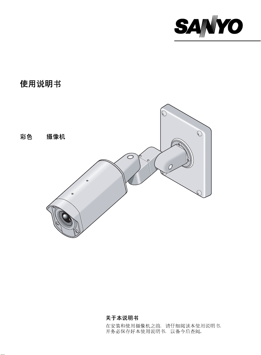
PARTS NAMES AND FUNCTIONS
4
3
English
H
G
2
1
9
Color display label
One-touch connector
F
5
8
Camera cover
6
7
1 Camera mount (See p5)
Used to install the camera to a wall or ceiling
with mounting screws (M8x4, sold
separately).
2 Camera position adjustment screws
(See p5)
You can use the hexagonal wrench (large,
accessory) to loosen these screws and then
adjust the direction of the camera. There are
four screws on the camera mount, four on
the camera itself and two on the arm section.
3 Camera fixing base (See p43)
4 Menu setting plate (See p11)
The camera can be set using menu
operations.
In addition, a monitor (sold separately) for
checking operation can be attached
temporarily.
CURSOR
MONITOR
MONITOR
CURSOR button
SET button
SET
(Monitor terminal)
GND
GND
(Ground terminal)
5 L-shaped camera fixing bracket (See p43)
6 Sunshade mounting bracket screw holes
(See p6)
Use the sunshade mounting bracket screws
(2, accessories) to install the sunshade.
7 Camera cover fixing screws
If you use a Phillips screwdriver to loosen
these four screws, you can then remove the
camera cover.
There is no need to remove the camera
cover except when using the menu setting
plate 4 or during maintenance.
If the camera cover has been removed,
tighten these screws to 0.5 N.m or more
when reinstalling it in order to ensure
watertightness.
CAUTION:
The camera cover will come off if the camera
cover fixing screws are loosened by about 5
mm, so be careful not to loosen them too
much. If a screw is loosened too much, the
drop-prevention washer inside the cover may
come off and the screw may fall out.
3
Page 5

8 Drop-prevention chain
Keep this attached at all times to prevent the
camera cover from falling down during
installation.
9 Camera fixing screws (See p43)
You can use the hexagonal wrench (small,
accessory) to loosen these screws and then
remove the camera.
F Video output connector (BNC type)
(See p7, 9)
Connection this connector to a device such
as a digital video recorder (or time lapse
VCR) or monitor with a VIDEO IN connector.
G Connection cord (See p7 – 10)
Connect to other devices in accordance with
the information on the color display label.
The power cord and the RS-485 have a
one-touch connector (accessory) attached.
H Connection cord hole (See p5)
If routing the connection cord outside the
wall, install the camera so that this hole is
facing downward and pull the connection
cord out from it.
English
4
Page 6
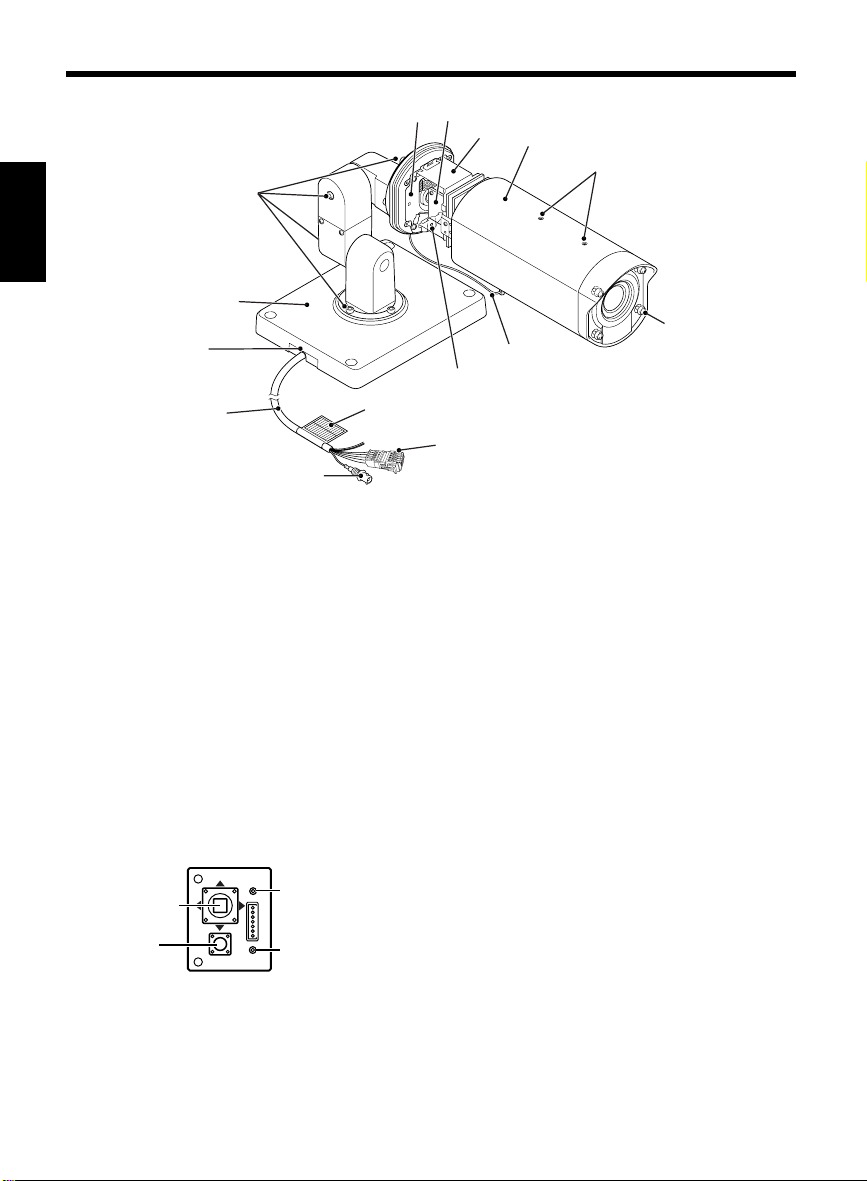
INSTALLATIONS
CAUTION:
Check that the installation location is strong enough to bear the camera before proceeding.
Setup location
English
• Install in a location (such as underneath overhangs) that is not exposed to direct sunlight.
• Install to a wall or ceiling with no unevenness in its surface.
If installing to a curved surface, round pillar or similar, use a special bracket (sold separately).
Setup
Use mounting screws (M8x4, sold
1
separately) to install the camera to the
wall or ceiling.
If routing the connection cord outside the
wall, install so that the connection cord hole
is facing downward, and pull the connection
cord out from the hole.
CAUTION:
Be sure to embed the mounting screws at
least 3 cm into the wall. If the screw holes
are too shallow, the camera mount may fall
down.
Connection cord hole
3 cm or more in
Mounting screw: M8
Adjust the position of the camera.
2
Use the hexagonal wrench (large,
accessory) to loosen the screws at the place
that you want to move, and then adjust the
direction of the camera.
After making the adjustment, securely
re-tighten the screws.
Maximum 90 degrees
(to prevent cord from twisting)
Screw tightening torque after adjustment:
2 N.m or more
Screw tightening torque after adjustment:
4.3 N.m or more
5
Page 7
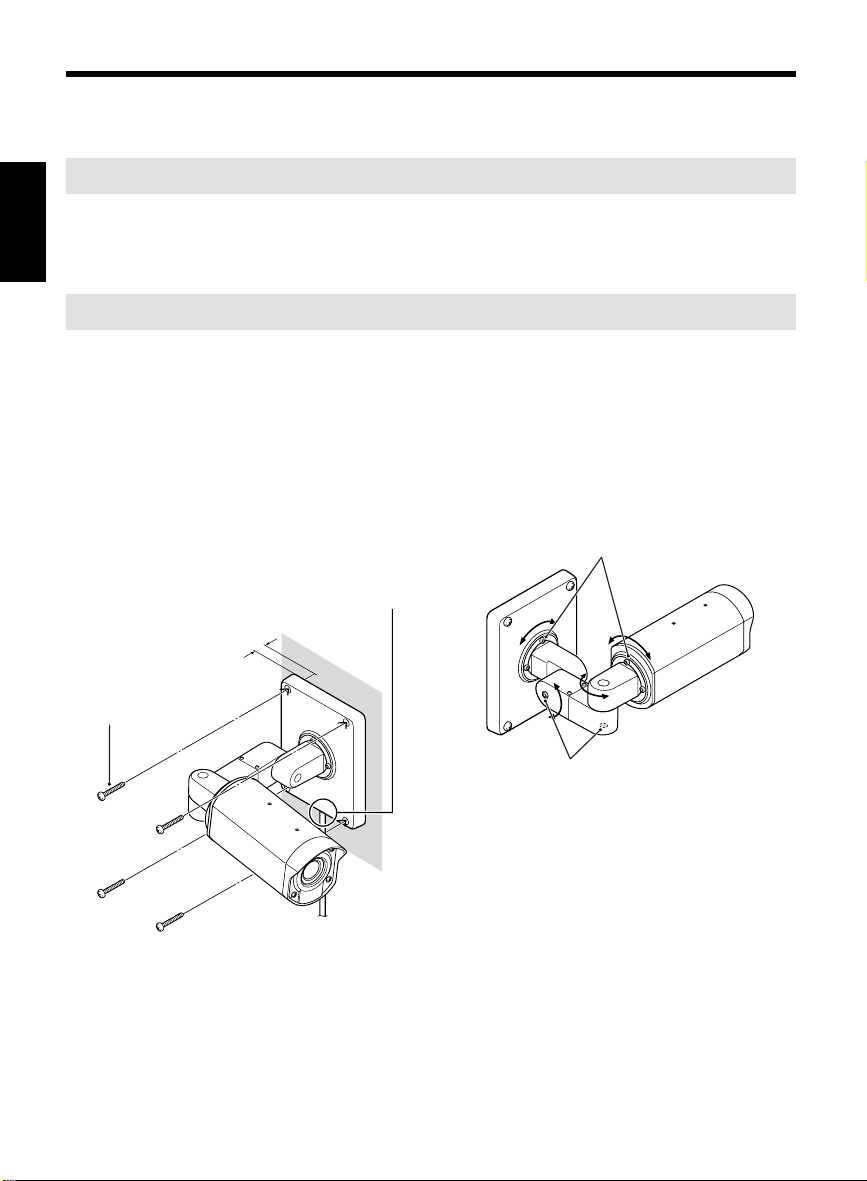
Attaching the plastic tie (accessory)
If you do not want the drop-prevention chain to hang down, move the camera to the required position
and then secure the chain with the plastic tie (accessory) as shown in the illustration below.
Drop-prevention chain
Plastic tie (accessory)
Press the tab on the
plastic tie as shown
at right to release it.
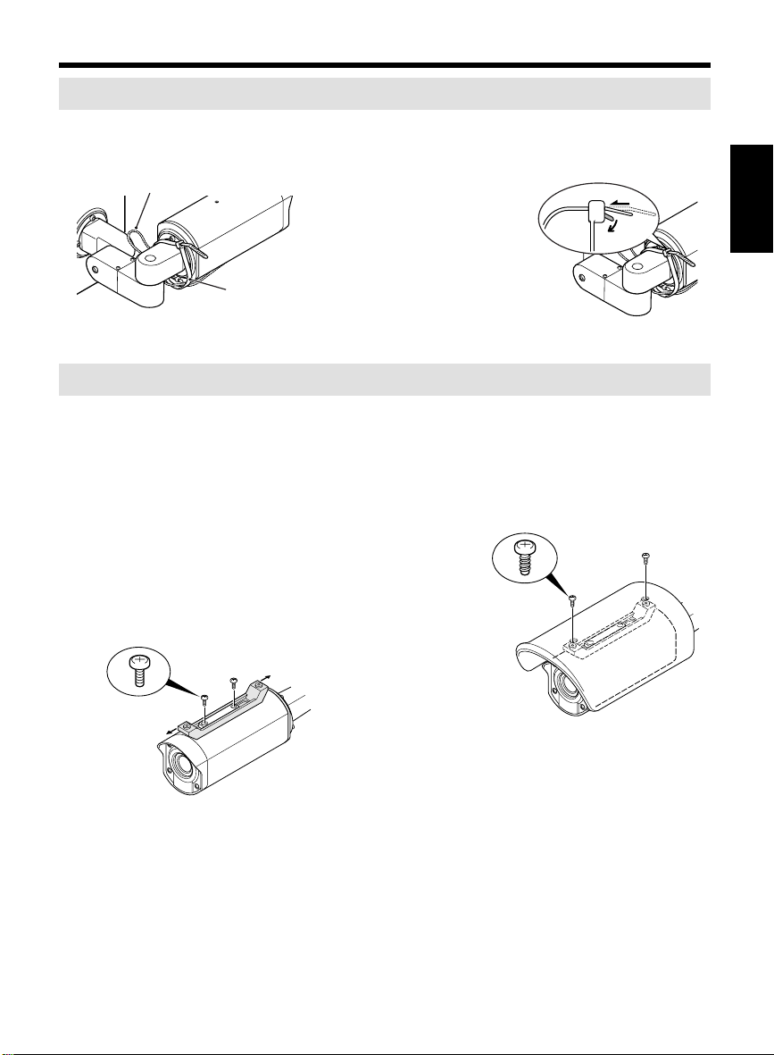
Installing the sunshade (accessory)
If direct sunlight may shine onto the camera at times (depending on the angle of the sun), install the
sunshade.
1
Use the two accessory screws to install
the sunshade mounting bracket
(accessory).
Determine the position of the sunshade so
that it will protect from direct sunlight as
much as possible, and adjust the position of
the sunshade mounting bracket back and
forth while the screws are still loose
(adjustment range: 30 mm). After adjusting
the bracket position, securely tighten the
screws. (Tightening torque: 0.5 N.m or more)
2
Use the two accessory screws
(self-tapping type) to install the sunshade
(accessory). (Tightening torque: 0.5 N.m
or more)
Self-tapping
screw for
plastic
English
6
Page 8
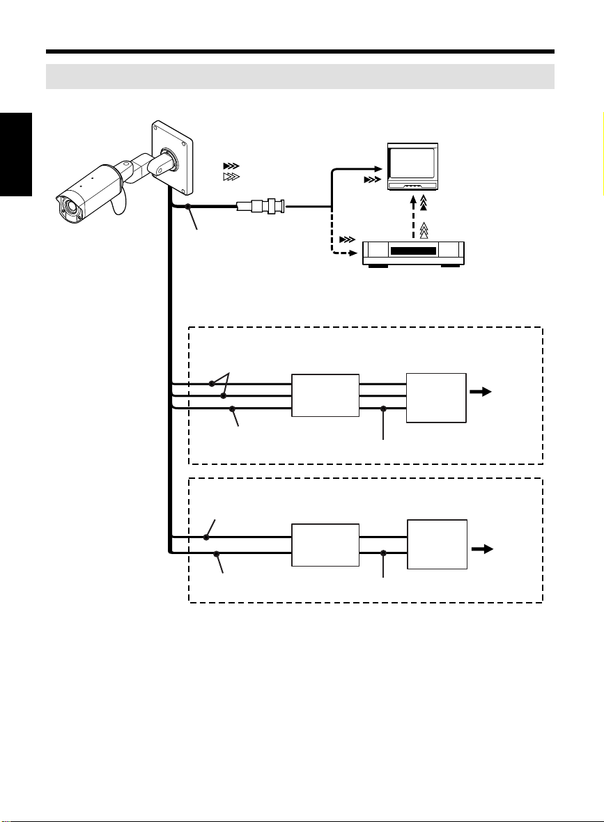
CONNECTIONS
Basic connection for monitoring or recording
CAUTION:
English
Do not connect the power cord until all other connections have been completed.
(Video signal)
VIDEO IN
VIDEO OUT
BLACK (VIDEO) cord
Fig.1 AC 24V connection
RED and WHITE (AC24V) cord
One-touch
connector
(accessory)
BROWN/BLACK (GND) cord
Fig. 2 DC 12V connection
RED (DC12V, +) cord
One-touch
connector
(accessory)
Digital video recorder or
Time lapse VCR
(sold separately)
Power supply adaptor
18AWG or more
Power supply adaptor
TV monitor
(sold separately)
~
AC24V
~
GND
+
DC12V
–
Into a
wall
outlet
Into a
wall
outlet
WHITE (DC12V, –) cord
Connect the video output connector (BNC type) of the BLACK (VIDEO) cord to the monitor or
digital video recorder (or time lapse VCR).
18AWG or more
7
Page 9

Connecting the power supply
CAUTION:
The power cord comes with a one-touch
connector (accessory) already attached. The
one-touch connector can be changed over if
required and it can also be used on other cords.
Connect a power supply adaptor or similar
device to the accessory one-touch connector.
(You can also remove the one-touch connector
and connect the other device directly.)
• When connecting to an AC power supply,
connect all three of the RED, WHITE and
BROWN/BLACK (GND) cords. There is no
difference between + and – connections.
(Fig. 1)
• When connecting to a DC power supply, be
sure to connect the RED cord to the + side
and the WHITE cord to the – side. (Fig. 2)
Connecting to the one-touch
connector
3
3
1
1
2
2
1
Use a flat-tipped screwdriver or similar
tool to push in the lever until a click is
heard.
2
Insert the end of the cord with the
insulation peeled back as far as it will go
into the hole.
• If part of the copper section of the wire is
protruding from the hole, trim the end of
the wire so that the exposed section of
wire goes all the way into the hole in
order to prevent short-circuits.
3
Push the tab to return the lever, and
check that the cord does not pull out.
Removing the one-touch connector
Use a flat-tipped screwdriver or similar tool to
push in the lever in step 1 above until it clicks,
and then pull out the cord.
English
8
Page 10
CONNECTIONS
Connecting to other equipment
The connection cords can be identified by color in accordance with the device they are to be
connected to (see the color display label). Connect whichever cords are required.
Note: If part of the copper section of a wire is exposed after a cord has been connected, trim the end
English
of the wire so that no copper section is exposed in order to prevent short-circuits.
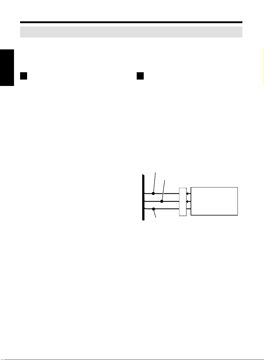
A Using a camera control unit to select
menus
• BLACK (VIDEO) cord:
If using menus, connect a VAC-60/70
camera control unit (sold separately).
The menus will be displayed on the monitor,
so that menu settings can be carried out
using the camera control unit without
needing to remove the camera cover from
the camera. Refer to the Instruction Manual
for the VAC-60/70 for further details.
Normally this cord should be connected to a
monitor or digital video recorder (or time
lapse VCR). (See p7)
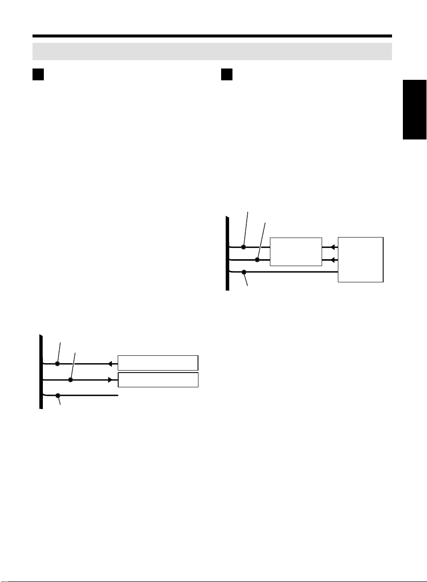
B Adjusting the zoom and focus
If a lens controller (applicable voltage: ±6 –
±12 V DC) or similar device is connected, it can
be used to carry out zoom and focus
adjustment. Refer to the Instruction Manual for
the lens controller for further details.
• ORANGE (ZOOM) cord:
This cord is used to input zoom signals to
the camera. It is used to make wide
angle/telescoping adjustments.
• YELLOW (FOCUS) cord:
This cord is used to input focus signals to the
camera. It is used to make far/near
adjustments.
ORANGE (ZOOM) cord
YELLOW (FOCUS) cord
Camera control unit
ZOOM signal
FOCUS signal
Ground
BROWN (GND) cord *
* The BROWN (GND) cord can be connected
to _B_, _C_ or _D_.
9
Page 11
C Using the alarm function
If a device with an alarm function that uses a
lamp or buzzer is connected to the camera, the
zoom ratio can be increased when an intruder is
detected. In addition, the DAY/NIGHT
(color/black & white) mode can also be selected.
However, only either the alarm function or the
mode selection function can be used at once
time. For either function, the settings in the
ALARM SETTING screen must be made.
(See p39)
• GRAY/BLACK (ALARM IN) cord:
This cord is used to input alarm signals or
DAY/NIGHT signals to the camera. The
alarm function for the connected device must
be set correctly. Refer to the Instruction
Manual for the connected device for further
details.
• BLUE (ALARM OUT) cord:
This cord is used to output alarm signals
from the camera. When the alarm function is
on, a buzzer or lamp can give a warning
when an intruder is detected.
Output rating: max. 18V, 25mA
(open collector, emitter
grounded)
GRAY/BLACK (ALARM IN) cord
BLUE (ALARM IN) cord
External alarm signal
D Using a system controller
When the camera is connected to the RS-485
terminal of a system controller, more than one
camera can be controlled at the same time.
Refer to the Instruction Manual for the system
controller for further details.
• GRAY (RS485 (A)) cord:
Connect to the RS-485 A terminal of the
system controller.
• ORANGE/BLACK (RS485 (B)) cord:
Connect to the RS-485 B terminal of the
system controller.
GRAY (RS485(A)) cord
ORANGE/BLACK (RS485(B)) cord
System controller
One-touch
connector
(accessory)**
BROWN (GND) cord *
RS485A
RS485B
Ground
** Connection is also possible if the one-touch
connector is removed. The one-touch
connector can be used on other cords after it
has been removed.
English
Buzzer or Lamp, etc.
Ground
BROWN (GND) cord *
10
Page 12
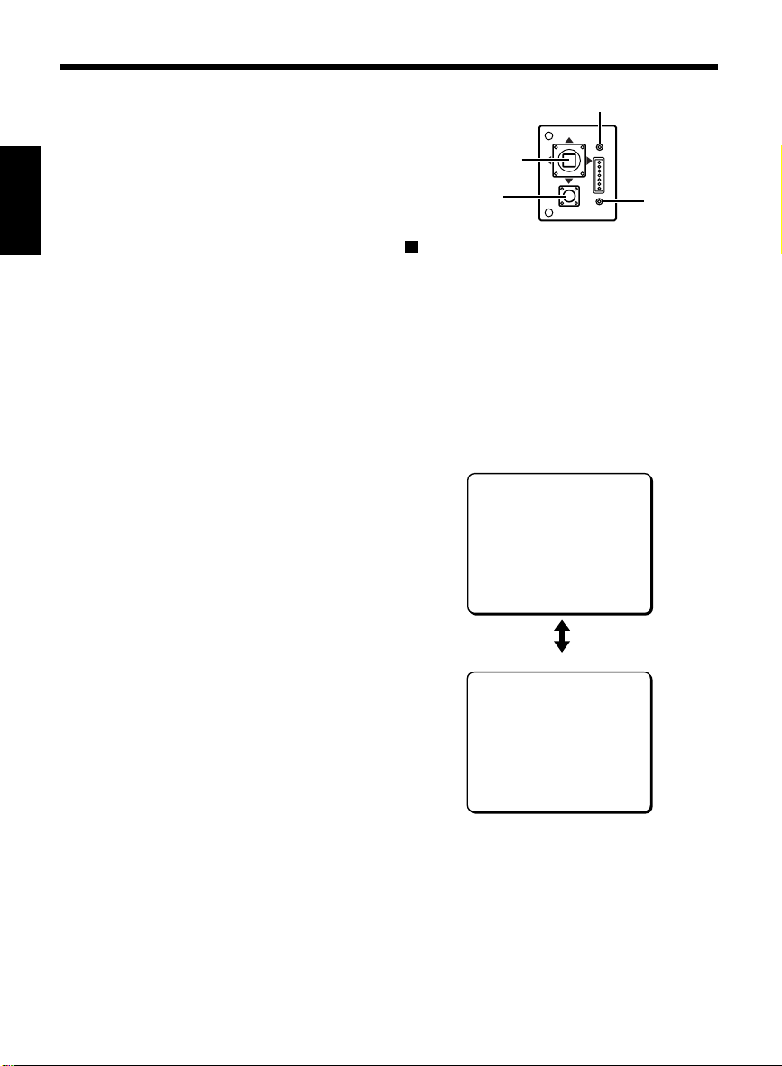
SETTING SCREEN AND BASIC OPERATIONS
Use a Phillips screwdriver to loosen the
1
four screws at the front of the camera,
and then remove the camera cover.
(See p3 7)
English
• If a camera control unit (VAC-60/70) or a
system controller (DSP-8000) is
connected to the RS-485 connector, you
do not need to remove the camera cover.
The menu screen will be displayed on the
monitor. Refer to the Instruction manual
for the controller for further details.
• If the monitor and the menu setting plate
(camera) are apart from each other and
this makes it difficult to carry out
operations, you can temporarily connect
the monitor to the MONITOR and GND
terminals of the setting plate using
alligator clips. However, be sure to
disconnect the alligator clips immediately
after making the settings.
Press the SET button for about 3 seconds.
2
The MAIN MENU screen will appear.
The default screen appears in English. To
☞
change the language to German or French,
refer to “LANGUAGE SETTING” on p13.
Use the CURSOR button (jldc) and
3
SET button to make the settings given
below.
• A list of functions appears at the left of
the setting screen, and the setting items
appear at the right.
• The flashing cursor position indicates the
currently-selected item.
• The return display (y) indicates that a
sub-menu exists. Press the SET button to
proceed to the next screen.
To close the MAIN MENU screen, use the
4
CURSOR button (j or l) to select END
for MENU, and then press the SET button.
• To return to the MAIN MENU screen from
a sub-menu, select BACK for MENU and
then press the SET button.
• To close a sub-menu, use the CURSOR
button (d or c) to change BACK to END
for MENU and then press the SET button.
CURSOR button
SET button
You can use just the CURSOR button to easily
adjust the zoom and focus without using the
setting screen.
• Zoom adjustment
• Focus adjustment
MONITOR (Monitor terminal)
CURSOR
MONITOR
SET
Simple zoom/focus adjustment
Press (d): Wide
Press (c): Tele
Press (j): Near
Press (l): Far
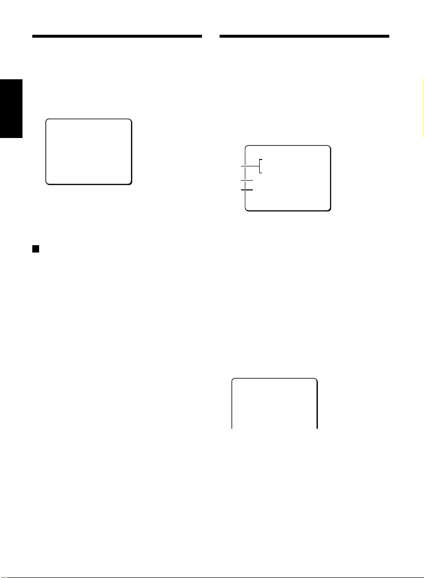
MAIN MENU screen
MAIN MENU
LANGUAGE SET ‚
CAMERA ID OFF
SYNC INT
PRIVACY MASK SET ‚
LENS SET ‚
MIRROR OFF
VIEW SETTING 1 ‚
OPTION SET ‚
PRESET OFF
MENU END
Sub-menu screen
LANGUAGE
LANGUAGE ENGLISH
LANGUE FRENCH
SPRACHE GERMANY
MENU BACK
GND
GND
(Ground
terminal)
11
Page 13
Operations of Setting screen
Refer to the pages given in the table below for each function for details on setting the functions.
MAIN MENU
(Function)
LANGUAGE
This lets you change the setting screen language to French or German.
Operation
(See p13)
CAMERA ID
(See p13)
If using more than one camera, this lets you assign different IDs to each
camera, and the IDs appear on the monitor.
SYNC (See p14) The sync method can be changed to Line-Lock (synchronizes the unit
with the power frequency).
The default setting is internal synchronization.
PRIVACY MASK
(See p15)
This covers an area of the screen with a gray pattern for areas that may
infringe on privacy. Gray patterns can be placed on up to 4 areas.
LENS (See p17) This lets you make settings such as automatic and manual focus settings,
zoom speed and zoom ratio. In addition, it can also be used for automatic
switching to color images during daytime, or to black and white images at
times of low luminance such as nighttime.
MIRROR (See p25) This lets you invert the images horizontally, vertically or horizontally and
vertically.
VIEW SETTING
(See p26)
Different detailed settings can be made for each camera (9 screens).
After they are set, these are linked to “VIEW SETTING (0 – 8)” settings
for preset positions.
OPTION (See p38) For setting communications conditions and alarms.
PRESET This returns all settings to their defaults.
The PRIVACY MASK menu and the CONTROL/ADDRESS settings in
☞
the OPTION menu will not be returned to their defaults.
English
Simple camera address confirmation
When connecting the power cord to an outlet, the camera address (See p39) is displayed on the
monitor for 5 – 15 seconds.
CAMERA ADDRESS
000
12
Page 14
LANGUAGE SETTING
CAMERA ID SETTING
If you change the language shown on the menu
screen to the French or German, make the
settings given below.
In the MAIN MENU, use the CURSOR
1
English
button (j or l) to select SET for
LANGUAGE, then press the SET button.
The LANGUAGE screen will appear.
LANGUAGE
LANGUAGE ENGLISH
LANGUE FRENCH
SPRACHE GERMANY
MENU BACK
Use the CURSOR button (j or l) and
2
SET button to select the desired
languages.
The interface language becomes French or
German.
To close the menu screen or return to the
previous screen, select BACK or END for
MENU and press the SET button.
If using more than one camera, this lets you
assign different names (IDs) to each camera,
and the IDs can be made to appear on the
monitor.
In the MAIN MENU, use the CURSOR
1
button (j or l) to move the cursor to
CAMERA ID, and then use the CURSOR
button (d or c) to change the setting to
ON. Then press the SET button.
The CAMERA ID SETTING screen will appear.
CAMERA ID SETTING
ABCDEFGHIJKLM
NOPQRSTUVWXYZ
1
0123456789 :-
ID ????????????????
2
3
-
POSITION SET ‚
PRESET OFF
MENU BACK
1 Character selection palette:
By moving the cursor to letters or numbers in
this palette, you can select characters.
2 ID:
Selected characters will appear in the
corresponding field under ID.
3 POSITION:
Set the position where the camera ID is to
appear on the monitor.
2
Example:
Setting the Camera ID to “CAM 1”
Use the CURSOR button (j l d c) to
move the cursor to the letter “C” in the
character selection palette, then press
the SET button.
CAMERA ID SETTING
ABCDEFGHIJKLM
NOPQRSTUVWXYZ
0123456789 :-‚
ID C???????????????
-
POSITION SET ‚
Use the same steps to select “A”, “M”
and “1” from the palette, then press the
SET button.
After at least one character is displayed in
☞
the ID field, the carriage return mark (y) will
appear at the lower right corner of the
character selection palette. Selecting this
mark between the characters of the field will
create a new line at that place.
13
Page 15
SYNC SETTING
Use the CURSOR button (j or l) to
3
move the cursor to SET for POSITION,
and then press the SET button.
The camera ID will be displayed on one line.
CAM1
Camera ID
Use the CURSOR button (j l d c) to
4
move the title display to the preferred
position on the screen, then press the
SET button.
The CAMERA ID SETTING screen will
reappear.
To return the settings in this screen to their
defaults, change PRESET to ON and then
press the SET button.
To close the menu screen or return to the
previous screen, select BACK or END for
MENU and press the SET button.
Default setting is internal synchronization (INT),
so it does not need to be set again. Follow the
steps below to change the setting to power
source synchronization (L-L).
However, vertical sync disturbance may occur
when a selector is used to switch between
multiple cameras connected to one monitor. To
prevent vertical sync disturbance, set to L-L
(Line-Lock).
In the MAIN MENU, use the CURSOR
1
button (j or l) to move the cursor to
SYNC, and then use the CURSOR button
(d or c) to change the setting to L-L.
Then press the SET button.
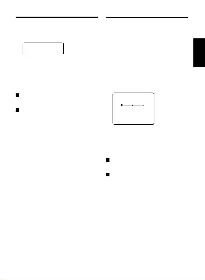
The L-L SETTING screen will appear.
L-L SETTING
(V SYNC PHASE)
0
PRESET OFF
MENU BACK
Use the CURSOR button (j or l) to
2
adjust the position of the vertical
synchronization indicator shown on the
screen.
The numerical value will change, allowing
adjustment of vertical synchronization.
To return the settings in this screen to their
defaults, change PRESET to ON and then
press the SET button.
To close the menu screen or return to the
previous screen, select BACK or END for
MENU and press the SET button.
English
14
Page 16

PRIVACY MASK SETTING
This covers an area of the screen with a gray pattern for areas that may infringe on privacy.
MASK setting
English
In the MAIN MENU, use the CURSOR
1
button (j or l) to select SET for
PRIVACY MASK, then press the SET
button.
The PRIVACY MASK SETTING screen will
appear.
PRIVACY MASK SETTING
PASSWORD LOCK OFF ‚
PASSWORD CHANGE SET ‚
MASK SET SET ‚
Use the CURSOR button (j or l) to
2
move the cursor to SET for MASK SET
and press the SET button.
The MASK NO. SELECT screen will appear.
MASK NO.SELECT
MASK 1 OFF
MASK 2 OFF
MASK 3 OFF
MASK 4 OFF
Note: When PASSWORD LOCK is ON, moving
the cursor to MASK SET and press the
SET button to bring up a password
access screen. The password must be
entered in this screen.
Use the CURSOR button (j or l) to
3
move the cursor to a mask number (e.g.
MASK 3), and then use the CURSOR
button (d or c) to change the setting to
SET. Then press the SET button.
The MASK SET (POSITION) screen will
appear.
MASK 3 SET
(POSITION)
Use the CURSOR button (jldc) to
4
move the gray mask, then press the SET
button.
The SIZE screen will appear, and the mask
that was positioned in the POSITION screen
will be displayed.
MASK 3 SET
(SIZE)
SET ‚
Use the CURSOR button (jldc) to
5
adjust the size of the gray mask, then
press the SET button.
Move the cursor to BACK for MENU and
6
press the SET button.
It is possible to set as many as 4 masks on
☞
the same POSITION screen.
To return the settings in this screen to their
defaults, change PRESET to ON and then
press the SET button.
To close the menu screen or return to the
previous screen, select BACK or END for
MENU and press the SET button.
SET ‚
15
Page 17

PASSWORD setting
PASSWORD setting
A
You can lock the privacy masks in place as gray
patterns after they have been set. The password
requirement is initially set to OFF, but to begin
using it, you must enter the factory set password
“1234”.
1
Use the CURSOR button (j or l) to
move the cursor to OFF for PASSWORD
LOCK in the PRIVACY MASK SETTING
screen. Then press the SET button.
The PASSWORD screen will appear.
PASSWORD
¤¤¤¤ SET ‚
2
Use the CURSOR button (
-
jldc
) to
enter the factory set password “1234”,
and then press the SET button.
“OK” will appear.
3
Press the SET button again.
The PRIVACY MASK SETTING screen will
reappear “ON” will be blinking for
PASSWORD LOCK.
PRIVACY MASK SETTING
PASSWORD LOCK ON ‚
PASSWORD CHANGE SET ‚
MASK SET SET ‚
PASSWORD LOCK cancellation
B
For use when PASSWORD LOCK is ON
1
Use the CURSOR button (j or l) to
move the cursor to ON for PASSWORD
LOCK in the PRIVACY MASK SETTING
screen. Then press the SET button.
The PASSWORD screen will appear.
PASSWORD
¤¤¤¤ SET ‚
2
Use the CURSOR button (
-
jldc
) to
enter the factory set password “1234”,
and then press the SET button.
“OK” will appear.
3
Press the SET button again.
The PRIVACY MASK SETTING screen will
reappear and “OFF” will be blinking for
PASSWORD LOCK.
PRIVACY MASK SETTING
PASSWORD LOCK OFF ‚
PASSWORD CHANGE SET ‚
MASK SET SET ‚
Note: If a different password is required, “NG”
will appear. Please carefully maintain the
password so that it will not be forgotten.
English
Note: If a different password is required, “NG”
will appear. Please carefully maintain the
password so that it will not be forgotten.
16
Page 18

PRIVACY MASK SETTING
LENS SETTING
PASSWORD setting
C
PASSWORD changes
English
You can change the password with
PASSWORD LOCK in either the ON or OFF
setting.
Use the CURSOR button (jldc) to
1
move the cursor to SET for PASSWORD
CHANGE in the PRIVACY MASK SETTING
screen. Then press the SET button.
The PASSWORD (NOW PASSWORD)
screen will appear.
PASSWORD
(NOW PASSWORD)
**** SET ‚
-
Use the CURSOR button (d or c, j) to
2
enter the current password (e.g.1234),
then press the SET button.
The PASSWORD (NEW PASSWORD)
screen will appear.
PASSWORD
(NEW PASSWORD)
**** SET ‚
-
Use the CURSOR button (d or c, j) to
3
enter a new password (e.g. 4321), then
press the SET button.
“OK” will appear.
Press the SET button again.
4
The PRIVACY MASK SETTING screen will
reappear.
To use the new password, please refer to
5
“ A PASSWORD setting”.
This lets you make settings such as automatic
and manual focus settings, zoom speed and
zoom ratio and DAY/NIGHT function settings.
FOCUS setting
These settings let you select automatic focus
(AUTO) or manual focus. Change the focus
settings in accordance with the monitoring
conditions.
In the MAIN MENU, use the CURSOR button
(j or l) to select SET for LENS, then press
the SET button.
The LENS screen will appear.
LENS
FOCUS MANU ‚
ZOOM SET ‚
A
Setting the manual focus (MANU)
Sets a limit for near distance focusing and sets
focus speed for manual focus.
Use the CURSOR button (jldc) to select
MANU for FOCUS, then press the SET button.
The FOCUS SETTING screen will appear.
FOCUS SETTING
LIMIT NEAR 1M
SPEED 2
LIMIT NEAR focus distance setting
Use the CURSOR button (j or l) to move
the cursor to LIMIT NEAR, then use the
CURSOR button (d or c) to change the
distance value.
Available settings: 1M (meter), 3M, 10C
Note: Focusing becomes difficult when near
distance limit is set to less than “1M”.
(centimeters), 30C, 50C
17
Page 19

SPEED of focus setting
Setting focus SENSITIVITY
Use the CURSOR button (j or l) to move
the cursor to SPEED, then use the CURSOR
button (d or c) to select the focus
adjustment speed value.
Available settings: 1, 2, 3, 4 (Quickest speed)
To return the settings in this screen to their
defaults, change PRESET to ON and then
press the SET button.
To close the menu screen or return to the
previous screen, select BACK or END for
MENU and press the SET button.
B
Setting the auto-focus (AUTO)
Sets a limit for near distance focusing and sets
focusing sensitivity and focus target area.
Note:
As a normal practice, use manual focus when
keeping the camera focused on the same target
object for a long period of time (over 24 hours).
This can be used with the one-push auto-focus
function when needed (operated from the
system controller). Long periods of surveillance
with the auto-focus in operation will shorten the
work life of the lens.
In the LENS screen, use the CURSOR button
(j or l) to select AUTO for FOCUS, then
press the SET button.
The FOCUS SETTING screen will appear.
FOCUS SETTING
LIMIT NEAR 1M
SENSITIVITY HIGH
AREA SET ‚
LIMIT NEAR focus distance setting
Use the CURSOR button (j or l) to move
the cursor to LIMIT NEAR, then use the
CURSOR button (d or c) to change the
distance value.
Available settings: 1M (meter), 3M, 10C
(centimeters), 30C, 50C
Note: Focusing becomes difficult when near
distance limit is set to less than “1M”.
Use the CURSOR button (j or l) to move
the cursor to SENSITIVITY, then use the
CURSOR button (d or c) to change the
setting.
Available settings:
HIGH: High sensitivity focusing
LOW: Low sensitivity focusing
Note: When focus SENSITIVITY is set to HIGH,
it may react to even slight movements of
the target object. In this case, change the
setting to LOW.
AREA setting
1
Use the CURSOR button (j or l) to
move the cursor to SET for AREA, and
press the SET button.
The AREA SETTING screen for AREA 2
(default setting) will appear to allow setting of
focus target area.
AREA SETTING
AREA 2
PRESET OFF
MENU BACK
2
Use the CURSOR button (d or c) to
select the focus target area.
Available settings: 1-full screen, 2-center of
screen, 3-smaller center
To return the settings in this screen to their
defaults, change PRESET to ON and then
press the SET button.
To close the menu screen or return to the
previous screen, select BACK or END for
MENU and press the SET button.
English
18
Page 20

LENS SETTING
ZOOM setting
Sets zooming speed and magnification power of the electronic zoom. This item also has a setting for
improvement of vertical resolution sensitivity of still pictures.
English
In the MAIN MENU, use the CURSOR
1
button (j or l) to select SET for LENS,
then press the SET button.
The LENS screen will appear.
LENS
FOCUS MANU ‚
ZOOM SET ‚
DAY/NIGHT AUTO ‚
Use the CURSOR button (j or l) to
2
select SET for ZOOM, then press the SET
button.
The ZOOM SETTING screen will appear.
ZOOM SETTING
SPEED 3
EL ZOOM OFF
V-RESO.UP OFF
SPEED (zoom speed) setting
Use the CURSOR button (d or c) to select
the zooming speed.
Available settings: 1, 2, 3, 4 (Quickest speed)
EL ZOOM (Electronic zoom) magnification
setting
Use the CURSOR button (j or l) to move
the cursor to EL ZOOM, then use the
CURSOR button (d or c) to select the
electronic zoom magnification power.
Available settings: OFF, x2, x4, x8, x16
(16 power)
V-RESO.UP (Vertical resolution sensitivity)
setting
Use the CURSOR button (j or l) to move
the cursor to V-RESO.UP, then use the
CURSOR button (d or c) to select the
vertical resolution sensitivity. (ON/OFF)
Note:
• When V-RESO.UP is set to “ON”, vertical
resolution sensitivity for still pictures in the
electronic zoom field will be improved but
afterimages of moving objects will be more
conspicuous.
• V-RESO. UP will be automatically set to
“OFF” when any of the following settings is
made.
IRIS SETTING: SENSE UP (x2…) (See p29)
VIEW SETTING: SHUTTER (LONG)
(See p33)
D/N SETTING: DNR (ON) (See p21)
To return the settings in this screen to their
defaults, change PRESET to ON and then
press the SET button.
To close the menu screen or return to the
previous screen, select BACK or END for
MENU and press the SET button.
19
Page 21

DAY/NIGHT setting
The DAY/NIGHT mode can be set to one of three settings (AUTO, COLOR or B/W) to improve the
appearance of images. This lets you set the filming mode to color mode during times of normal
brightness, or to black & white mode to increase sensitivity when there is less light. When you select a
mode, you may then need to make detailed settings for the respective mode used.
Note:
• When “COLOR” is selected, the mode is
fixed at color and you can only view images
that are in color. The same applies to B/W
mode. However, you can also use the
ALARM IN terminal on the rear panel to
force the mode to change from COLOR to
B/W or from B/W to COLOR. Refer to the
“COLOR (Color or Black/White selection
setting)” for details on the setting method.
(See p40)
• A sound may be heard when the color image
or black and white image is switched. Also,
the image will be distorted as shown in
Fig. 1. This is normal and does not indicate
a problem.
Fig. 1
• When using infrared lighting, if there is a
strong reflection on the subject, the optical
filter may switch from black and white to
color mode. Use only enough infrared
lighting so that the mode is not switched.
In the MAIN MENU, use the CURSOR button
(j or l) to select SET for LENS, then press
the SET button.
The LENS screen will appear.
LENS
FOCUS MANU ‚
ZOOM SET ‚
DAY/NIGHT AUTO ‚
VIEW ANGLE OFF
PRESET OFF
MENU BACK
AUTO mode setting
A
Automatic mode; The mode switches
automatically between color mode and black &
white mode depending on the luminance of the
objects being monitored.
Note:
• If the backlight compensation has been set
to “MULT”, the backlight compensation will
be canceled when the mode is switched to
B/W.
• If “SENSE UP” has been activated, SENSE
UP mode will be activated after the mode
switches to B/W mode.
Use the CURSOR button (j or l) to move
the cursor to DAY/NIGHT, use the CURSOR
button (d or c) to select the mode (AUTO),
and then press the SET button.
The D/N SETTING – AUTO screen will appear.
D/N SETTING - AUTO
AGC MAX GAIN +9·
DNR OFF
BURST OFF
FOCUS 1
LEVEL MID
English
20
PRESET OFF
MENU BACK
Page 22

LENS SETTING
DAY/NIGHT setting
AGC MAX GAIN setting
Use the CURSOR button (j or l) to move
English
the cursor to AGC MAX GAIN, and then use
the CURSOR button (d or c) to select the
maximum AGC gain.
Available settings: +9dB, +12dB, +15dB
DNR setting
Use the CURSOR button (j or l) to move
the cursor to DNR, and then use the
CURSOR button (d or c) to select the
digital noise reduction setting.
Available settings:
ON: DNR (digital noise reduction) is applied.
This reduces interference at low luminance
levels.
OFF: DNR is not applied.
Note: Digital noise reduction operates when the
gain control increases. In addition,
blurring and ghosting of images can
occur when moving images are being
monitored, and so the resolution is also
reduced slightly.
BURST setting
Sets burst suppression. If other peripheral
devices (such as a multiplexer) are connected to
the system, bursts (distortion of image color)
can occur when switching between color and
black & white. If this happens, change the
BURST setting to “ON”.
Use the CURSOR button (j or l) to move
the cursor to BURST, and then use the
CURSOR button (d or c) to select the burst
setting.
Available settings:
ON: The color burst signal is turned on.
OFF: This should normally be set to “OFF”.
FOCUS setting
Sets the focus when switching to black & white
mode.
Use the CURSOR button (j or l) to move
the cursor to FOCUS, and then use the
CURSOR button (d or c) to select the focus
setting.
Available settings:
1: Near-infrared wavelength correction is set.
(around 900 nm)
2: Visible light spectrum is set.
Note: This is set to “1” at the time of shipment
from the factory. If the images are out of
focus, change it to “2”.
LEVEL setting
Sets the switching level for color mode and
black & white mode. The three available settings
are LOW, MID or HIGH. In addition, the
switching level can be set manually (ADJ; see
p22).
Available settings:
LOW: The mode switches when the luminance
of the objects being monitored is
comparatively dark.
MID: The mode switches when the luminance
of the objects being monitored is between
the LOW and HIGH levels.
HIGH: The mode switches when the luminance
of the objects being monitored is
comparatively bright.
ADJ: The switching level for color mode to
black & white mode and for black & white
mode to color mode respectively can be
set manually.
21
Page 23

ADJ settings:
1
Use the CURSOR button (j or l) to
move the cursor to LEVEL, use the
CURSOR button (d or c) to select the
level setting (ADJ) and then press the
SET button.
The LEVEL SETTING screen will appear.
LEVEL SETTING
(COLOR†B/W)
4
(B/W†COLOR)
4
2
Use the CURSOR button (j or l) to
move the cursor to COLORüB/W, and
then use the CURSOR button (d or c) to
select the value.
Set the switching the level from black &
☞
white mode to color mode in the same
way.
Available settings: 1 – 7
Note:
• The larger the value, the darker the
switching level.
• Changing the setting for one of the switching
level settings (from color mode to black &
white mode or from black & white mode to
color mode) causes the other setting to
change also.
B
COLOR mode setting
Color mode; Images are filmed in color
regardless of the luminance of the objects being
monitored.
In the LENS screen, use the CURSOR button
(j or l) to move the cursor to DAY/NIGHT,
use the CURSOR button (d or c) to select
the level setting (COLOR) and then press the
SET button.
The D/N SETTING – COLOR screen will appear.
D/N SETTING - COLOR
AGC MAX GAIN ±0·
DNR OFF
AGC MAX GAIN setting
Use the CURSOR button (j or l) to move
the cursor to AGC MAX GAIN, and then use
the CURSOR button (d or c) to select the
maximum AGC gain.
Available settings: OFF, –6dB, ±0dB, +6dB,
+9dB
Note:
• If “OFF” is selected, no maximum gain will be
set.
• If “OFF” is selected, the SENSE UP function
will be forcibly set to “OFF”. However, the
setting display will not change.
English
22
Page 24

LENS SETTING
DAY/NIGHT setting
Setting fixed gain manually
Set AGC MAX GAIN to “OFF” and then press
English
the SET button.
The GAIN SETTING screen will appear. You
can use this screen to set the gain value
manually to within a range of 0 – 30 dB.
GAIN SETTING
0·
DNR setting
Use the CURSOR button (j or l) to move
the cursor to DNR, and then use the
CURSOR button (d or c) to select the
digital noise reduction setting.
Available settings:
ON: DNR (digital noise reduction) is applied.
This reduces interference at low luminance
levels.
OFF: DNR is not applied.
Note:
• Digital noise reduction operates when the
gain control increases. In addition, blurring
and ghosting of images can occur when
moving images are being monitored, and so
the resolution is also reduced slightly.
• If AGC MAX GAIN is set to “OFF”, DNR will
be forcibly set to “OFF”.
To return the settings in this screen to their
defaults, change PRESET to ON and then
press the SET button.
To close the menu screen or return to the
previous screen, select BACK or END for
MENU and press the SET button.
C
B/W mode setting
Black & white mode; Images are filmed in black
& white regardless of the luminance of the
objects being monitored.
In the LENS screen, use the CURSOR button
(j or l) to move the cursor to DAY/NIGHT,
use the CURSOR button (d or c) to select
the level setting (B/W) and then press the
SET button.
The D/N SETTING – B/W screen will appear.
D/N SETTING - B/W
AGC MAX GAIN +6·
DNR OFF
BURST OFF
FOCUS 1
AGC MAX GAIN setting
Use the CURSOR button (j or l) to move
the cursor to AGC MAX GAIN, and then use
the CURSOR button (d or c) to select the
maximum AGC gain.
Available settings: OFF, –6dB, ±0dB, +6dB,
+9dB, +12dB, +15dB
Note:
• If “OFF” is selected, no maximum gain will be
set.
• If “OFF” is selected, the SENSE UP function
will be forcibly set to “OFF”. However, the
setting display will not change.
Setting fixed gain manually
Set AGC MAX GAIN to “OFF” and then press
the SET button.
The GAIN SETTING screen will appear. You
can use this screen to set the gain value
manually to within a range of 0 – 30 dB.
GAIN SETTING
23
0·
Page 25

DNR setting
FOCUS setting
Use the CURSOR button (j or l) to move
the cursor to DNR, and then use the
CURSOR button (d or c) to select the
digital noise reduction setting.
Available settings:
ON: DNR (digital noise reduction) is applied.
This reduces interference at low luminance
levels.
OFF: DNR is not applied.
Note:
• Digital noise reduction operates when the
gain control increases. In addition, blurring
and ghosting of images can occur when
moving images are being monitored, and so
the resolution is also reduced slightly.
• If AGC MAX is set to “OFF”, DNR will be
forcibly set to “OFF”.
BURST setting
Sets burst suppression. If other peripheral
devices (such as a multiplexer) are connected to
the system, bursts (distortion of image color)
can occur when switching between color and
black & white. If this happens, change the
BURST setting to “ON”.
Use the CURSOR button (j or l) to move
the cursor to BURST, and then use the
CURSOR button (d or c) to select the burst
setting.
Available settings:
ON: The color burst signal is turned on.
OFF: This should normally be set to “OFF”.
Sets the focus when switching to black & white
mode.
Use the CURSOR button (j or l) to move
the cursor to FOCUS, and then use the
CURSOR button (d or c) to select the focus
setting.
Available settings:
1: Near-infrared wavelength correction is set.
(around 900 nm)
2: Visible light spectrum is set.
Note: This is set to “1” at the time of shipment
from the factory. If the images are out of
focus, change it to “2”.
To return the settings in this screen to their
defaults, change PRESET to ON and then
press the SET button.
To close the menu screen or return to the
previous screen, select BACK or END for
MENU and press the SET button.
D
Day/Night mode operation from the
system controller
The Day/Night setting (AUTO, COLOR and
B/W) can be switched using “CAMERA”
operating range of the system controller. Press
the following buttons in the order given to
change the mode setting.
COLOR mode:
“AUX” → “AUX” → “1” → “ENTER” → “+” button
B/W mode:
“AUX” → “AUX” → “2” → “ENTER” → “+” button
AUTO mode:
“AUX” → “AUX” → “3” → “ENTER” → “+” button
English
24
Page 26

LENS SETTING
MIRROR SETTING
VIEW ANGLE setting
The VIEW ANGLE setting should normally be
left at “OFF”.
English
In the MAIN MANU, use the CURSOR
1
button (j or l) to select SET for LENS,
then press the SET button.
The LENS screen will appear.
LENS
FOCUS MANU ‚
ZOOM SET ‚
DAY/NIGHT B/W ‚
VIEW ANGLE OFF
PRESET OFF
MENU BACK
Use the CURSOR button (j or l) to
2
move the cursor to VIEW ANGLE, and
then use the CURSOR button (d or c) to
select the setting.
Available settings:
OVER: The image angle for images being
monitored is set to 1.05.
OFF: This should normally be set to “OFF”.
Note: This should normally be set to “OFF”.
However, vignetting may occur in the
corners of the images because of the
zoom position. This is not normally a
problem, but if you are concerned about
it, change the setting to “OVER”. The
vignetting will then be less apparent.
To return the settings in this screen to their
defaults, change PRESET to ON and then
press the SET button.
To close the menu screen or return to the
previous screen, select BACK or END for
MENU and press the SET button.
In the MAIN MENU, use the CURSOR button
(j or l) to move the cursor to MIRROR,
then use the CURSOR button (d or c) to
select the mirror image effect.
MAIN MENU
LANGUAGE SET ‚
CAMERA ID OFF
SYNC INT
PRIVACY MASK SET ‚
LENS SET ‚
MIRROR OFF
VIEW SETTING 1 ‚
OPTION SET ‚
PRESET OFF
MENU END
Available settings:
OFF: Normal image
H: Inverted horizontally
V: Inverted vertically
HV: Inverted horizontally and vertically
OFF H V HV
To return to the normal screen, use the
CURSOR button (l) to select END at the
bottom of the screen, then press the SET
button.
25
Page 27

VIEW SETTING
In the MAIN MENU, use the CURSOR button
(j or l) to move the cursor to the file
number (e.g. 1) for VIEW SETTING, then
press the SET button.
The selected image setting file (e.g. VIEW
SETTING 1 screen) will appear.
VIEW SETTING 1
IRIS AUTO ‚
WHITE BALANCE ATW ‚
SHUTTER OFF
MOTION OFF
APERTURE ON ‚
GAMMA ON
PRESET OFF
MENU BACK
You can set 9 different patterns with view
☞
files.
Signifies that VIEW SETTING 1 is the
camera setting 1. The CURSOR button
(d or c) can be usedto select one of the
nine VIEW SETTING patterns (0 – 8).
Neither the mask function nor the motion
detector function can be used with image
setting file “0”, so they will not appear as
options in the screen for pattern 0.
Operations of VIEW SETTING screen
Refer to the pages given in the table below for each function for details on setting the functions.
VIEW SETTING
(Function)
Operation
IRIS (See p27) There are 2 possible settings for IRIS, autoiris (AUTO) and manual iris
(MANU).
WHITE BALANCE
(See p31)
Three white balance methods are available: Auto trace white balance (ATW),
one-push automatic white balance (AWC), and manual white balance (MWB).
SHUTTER (See p33) Sets the electronic shutter to either the fast shutter speed mode (SHORT) or
the slow shutter speed mode (LONG).
MOTION (See p34) This function generates an alarm when a suspicious figure is detected. Each
of the settings will enable certain kinds of detection based on the natural
image (swaying trees, flickers of light, etc.). It is also possible to enable
zooming in on target objects and intruders that have unusual brightness
levels (moving, bright) or are fast-moving.
APERTURE
This setting emphasizes the target object profile (horizontally or vertically).
(See p37)
GAMMA (See p37) This setting enables contrast sensitivity to be boosted by controlling the
gamma characteristics. Three gamma controls are available: gamma
correction (ON), smart gamma correction 1 (SMART 1), and smart gamma
correction 2 (SMART 2).
Note: When each of the following functions is ON “F”, it may be possible to use other function in
conjunction with it “E”. View columns vertically to determine which functions can be used
together.
English
IRIS AUTO: SENSE UP (activated) FTTTT
MANU: EI (ON) TFTTE
SHUTTER LONG TTFTT
SHORT
MOTION
F: Function is set T: Not allowable E: Allowable
TTTFE
TETEF
26
Page 28

VIEW SETTING
IRIS setting
There are 2 possible settings for IRIS, autoiris (AUTO) and manual iris (MANU).
A
English
Auto-iris setting (AUTO)
Sets backlight compensation, magnification of
electronic sensitivity and iris level.
In the VIEW SETTING screen, use the
CURSOR button (jldc) to select AUTO
for IRIS, then press the SET button.
The IRIS SETTING screen will appear.
IRIS SETTING
BLC OFF
SENSE UP OFF
(LEVEL)
40
BLC (backlight compensation) settings
When AUTO is selected, the following 3 types of
detailed backlight compensation settings will be
available.
MULT (Multi-spot evaluative metering):
1
Evaluates the entire screen and corrects
according to the best image obtained.
Use the CURSOR button (jldc) to
1
select MULT for BLC, then press the SET
button.
The BLC SETTING screen will appear.
BLC SETTING
(BLC WEIGHT)
7
(BRIGHT)
7
To return the settings in this screen to their
defaults, change PRESET to ON and then
press the SET button.
To close the menu screen or return to the
previous screen, select BACK or END for
MENU and press the SET button.
Note:
• When using multi-spot evaluative metering,
the background behind the target object will
become very dark. If a target image in the
center of the image is too bright while using
the multi-spot evaluative metering mode,
switch to the 5 spot center-weighted average
metering mode.
• If DAY/NIGHT is set to “AUTO” and the
images are in black & white mode, multi-spot
evaluative metering will not operate.
CENT (5 spot center-weighted average
2
metering):
Covers bright areas such as persons with mask
patterns and treats light measurement output as
irrelevant.
Use the CURSOR button (jldc) to
1
select CENT for BLC, then press the SET
button.
The BLC SETTING (POSITION) screen will
appear.
BLC SETTING
(POSITION)
Use the CURSOR button (jldc) to
2
make the settings given below.
BLC WEIGHT: Sets backlight and
brightness level
Available settings: 0 – 15
• The larger the number, the more
backlight works.
BRIGHT: Sets compensation level
Available settings: 0 – 15
• When the number becomes larger, it
brightens, and the compensation level
can be set for the brightness of the
backlighting.
27
Page 29

2
Use the CURSOR button (
jldc
) to
shift the position of the central light
sensing zone.
The zone can be moved up or down and left
or right.
Note:
• If the zone fills the right side it will become
smaller.
• If the zone fills the bottom side it will become
smaller.
3
Press the SET button.
The BLC SETTING (SIZE) screen will
appear.
BLC SETTING
(SIZE)
4
Use the CURSOR button (
jldc
) to
adjust the size of the central light sensing
zone.
The zone can be moved up or down and left
or right.
5
Press the SET button.
The BLC WINDOW WEIGHTING screen will
appear.
BLC WINDOW WEIGHTING
TOP 0
BOTTOM 0
LEFT 0
RIGHT 0
CENTER(FIX) 7
PRESET OFF
MENU BACK
6
Use the CURSOR button (j or l) to
select a zone, then use the CURSOR
button (d or c) to adjust weighting.
The weighting for each zone except for the
CENTER zone can be adjusted within the
range 0 – 7.
TOP: Weighting is at top.
BOTTOM: Weighting is at bottom.
LEFT: Weighting is at left.
RIGHT: Weighting is at right.
CENTER (FIX): Center weighting is fixed by
the number 7.
Note: If this is set to “0”, the light intensity will
be ignored. The larger the setting value,
the greater is the weighting given to light
coming from the respective side.
To return the settings in this screen to their
defaults, change PRESET to ON and then
press the SET button.
To close the menu screen or return to the
previous screen, select BACK or END for
MENU and press the SET button.
3
MASK (48 multi-spot metering):
Measures light mainly at the center and corrects
according to the best image obtained.
1
Use the CURSOR button (
jldc
) to
select MASK for BLC, then press the SET
button.
The BLC MASKING screen will appear.
BLC MASKING
CONTINUE (ñ)
English
28
Page 30

VIEW SETTING
IRIS setting
Use the CURSOR button (jldc) to
2
move the cursor to move the mask
English
pattern over the area not to be sensed,
then press the SET button.
The mask pattern will be set. You can use
☞
the same steps to set additional mask
patterns.
Note: The initial mask pattern is at the upper
left of the screen, and it is not set. To
clear a mask pattern after it is set, press
the SET button again.
Use the CURSOR button (l) to move a
3
mask pattern to the bottom area of the
screen and continue holding it for 3
seconds.
To return the settings in this screen to their
defaults, change PRESET to ON and then
press the SET button.
To close the menu screen or return to the
previous screen, select BACK or END for
MENU and press the SET button.
SENSE UP setting
Use the CURSOR button (j or l) to move
the cursor to SENSE UP, then use the
CURSOR button (d or c) to select the
power of the electronic sensitivity.
IRIS SETTING
BLC MULT
SENSE UP x4
(LEVEL)
40
Available settings: OFF, x2, x4, x8, x16, x32
Note:
• Electronic sensitivity boosting (SENSE UP)
automatically lengthens the CCD exposure
time in dark situations. Accordingly, do not
use for light target objects. Because
exposure time is lengthened while in
operation, moving target objects may cause
conspicuous after images and blurs.
• It is not possible to set SENSE UP
(activated) or SHUTTER (LONG) when
MOTION is set to “ON”.
• When SENSE UP is activated for IRIS
SETTING, the electronic shutter cannot be
forcibly moved.
• If DAY/NIGHT is set to “AUTO” and the
images are in color mode, electronic
sensitivity boosting will not operate.
To return the settings in this screen to their
defaults, change PRESET to ON and then
press the SET button.
To close the menu screen or return to the
previous screen, select BACK or END for
MENU and press the SET button.
LEVEL setting
Use the CURSOR button (j or l) to move
the cursor to LEVEL, then use the CURSOR
button (d or c) to adjust the iris level.
IRIS SETTING
BLC MULT
SENSE UP x4
(LEVEL)
40
Available settings: 0 – 100
• The larger the number, the more it brightens.
To return the settings in this screen to their
defaults, change PRESET to ON and then
press the SET button.
To close the menu screen or return to the
previous screen, select BACK or END for
MENU and press the SET button.
29
Page 31

B
Manual-iris setting (MANU)
Sets electronic iris on/off, lens aperture and iris
level.
In the VIEW SETTING screen, use the
1
CURSOR button (jldc) to select
MANU for IRIS, then press the SET button.
The IRIS SETTING screen will appear.
IRIS SETTING
EI OFF
(IRIS STOP)
17
(LEVEL)
40
Use the CURSOR button (jldc) to
2
make the settings given below.
1 EI: Electronic IRIS setting (ON/OFF)
Note: When SENSE UP is activated for IRIS
SETTING, the electronic shutter
cannot be forcibly moved.
2 IRIS STOP: Lens aperture setting
Available settings: 1 – 17 (Aperture
opening)
• The smaller the value, the more the
aperture closes and the image darkens.
Note: Changes to the value directly control
the aperture of the lens.
3 LEVEL: Lens iris setting
Available settings: 0 – 100 (Level of
opening)
• The smaller the value, the more the video
level drops, becoming darker.
Note: The LEVEL setting controls both AGC
circuit gain and shutter speed,
changing the amount of exposure.
Note:
• If the iris views an unusually bright image, it
can cause a smear that cannot be corrected
by adjusting the light entering through the
lens. In this case, arrange the physical angle
of lighting in a way that will prevent
on-screen smearing.
• If flickering of the target object occurs
because of florescent lighting in the camera
location, changing to incandescent lighting
will prevent the flickering.
To return the settings in this screen to their
defaults, change PRESET to ON and then
press the SET button.
To close the menu screen or return to the
previous screen, select BACK or END for
MENU and press the SET button.
English
30
Page 32

VIEW SETTING
WHITE BALANCE adjustment
Three white balance methods are available: Auto trace white balance (ATW), one-push automatic
white balance (AWC), and manual white balance (MWB). Default setting is auto trace white balance.
English
A
ATW setting
Automatic white balance settings are completed
when ATW is selected. However, white balance
will not be suitably adjusted if a bright light
source or an excessively dark area from the
environment is in the image. In this case, the
bright light source or dark area should be
masked so that it will not be detected.
In the VIEW SETTING screen, use the
CURSOR button (jldc) to select ATW for
WHITE BALANCE, then press the SET button.
The ATW SETTING screen will appear.
ATW SETTING
MASKING OFF ‚
SMART ATW OFF
MASKING setting
Use the CURSOR button (jldc) to
1
select ON for MASKING, then press the
SET button.
The ATW MASKING screen will appear.
ATW MASKING
Use the CURSOR button (l) to move a
3
mask pattern to the bottom area of the
screen and continue holding the CURSOR
button straight down for 3 seconds.
To return the settings in this screen to their
defaults, change PRESET to ON and then
press the SET button.
To close the menu screen or return to the
previous screen, select BACK or END for
MENU and press the SET button.
SMART ATW setting
If saturation is high or a scene is bright, the
most suitable colors may not be obtained. In this
case, set the SMART ATW to ON.
Use the CURSOR button (jldc) to select
ON for SMART ATW, then press the SET
button.
To return the settings in this screen to their
defaults, change PRESET to ON and then
press the SET button.
To close the menu screen or return to the
previous screen, select BACK or END for
MENU and press the SET button.
CONTINUE (ñ)
Use the CURSOR button (jldc) to
2
move the mask pattern over the bright
light source, then press the SET button.
Use the same steps to place addition masks
as needed.
Note: Initial settings place no masks on the
screen. To cancel the placement of
masks, press the SET button again.
B
AWC setting
White balance is adjusted automatically with
one-push activation. AWC is usually set for
white target objects (walls, paper, etc.) that do
not return color faithfully in the ATW method.
In the VIEW SETTING screen, use the
CURSOR button (jldc) to select AWC for
WHITE BALANCE, then press the SET button.
The AWC SETTING screen will appear.
AWC SETTING
AWC LOCK SET
GO TO MWB SET ‚
31
Page 33

AWC LOCK setting
With SET blinking for AWC LOCK, press the
SET button.
SET will light and adjustment of white balance
will begin. After about 3 seconds, SET will begin
blinking again, signaling that adjustment is
complete.
Note: Full adjustment may not be possible with
just one activation of SET for AWC
LOCK. In that case, press the SET button
again.
To return the settings in this screen to their
defaults, change PRESET to ON and then
press the SET button.
To close the menu screen or return to the
previous screen, select BACK or END for
MENU and press the SET button.
GO TO MWB setting
For even finer adjustment of coloration, choose
SET for GO TO MWB. White balance mode will
become MWB for fine adjustment. After fine
adjustment with GO TO MWB, the white
balance mode will automatically switch to MWB.
Go to “_C_ MWB setting”.
C
MWB setting
Fine adjustments for preferred colors can be
done manually. This method is preferable when
suitable colors cannot be obtained with the ATW
method.
In the VIEW SETTING screen, use the
1
CURSOR button (jldc) to select MWB
for WHITE BALANCE, then press the SET
button.
The MWB SETTING screen will appear.
MWB SETTING
(OFFSET)
R 64
B 64
Use the CURSOR button (jldc) to
2
make the settings given below.
1 R: red
Available settings: 0 – 255
• The larger the number, the stronger red
becomes.
2 B: blue
Available settings: 0 – 255
• The larger the number, the stronger blue
becomes.
To return the settings in this screen to their
defaults, change PRESET to ON and then
press the SET button.
To close the menu screen or return to the
previous screen, select BACK or END for
MENU and press the SET button.
English
32
Page 34

VIEW SETTING
SHUTTER setting (Electronic shutter)
This setting chooses either a fast shutter speed (SHORT) for target objects that may be moving quickly
or a slower shutter speed (LONG) for darker target objects.
English
A
SHORT (Fast shutter speed mode
setting)
In the VIEW SETTING screen, use the
1
CURSOR button (jldc) to select
SHORT for SHUTTER, then press the SET
button.
The ES SETTING screen will appear.
This setting is suitable for fast moving target
objects.
ES SETTING
SHUTTER SPEED 50
Use the CURSOR button (d or c) to
2
select an electronic shutter speed.
Available settings: 50, 120, 250, 500,
Note: SHORT mode cannot be set if
SENSE UP is activated or IRIS is
“ON”.
To return the settings in this screen to their
defaults, change PRESET to ON and then
press the SET button.
To close the menu screen or return to the
previous screen, select BACK or END for
MENU and press the SET button.
1000, 2000, 4000,
10000.
B
LONG (Slow shutter speed mode
setting)
In the VIEW SETTING screen, use the
1
CURSOR button (jldc) to select
LONG for SHUTTER, then press the SET
button.
The ES SETTING screen will appear.
This setting is suitable for dark target objects.
ES SETTING
SHUTTER SPEED ¶1
Note: When setting the electronic shutter, the
ELS button on the system controller can
only be used to turn the electronic shutter
on and off.
Use the CURSOR button (d or c) to
2
select an electronic shutter speed.
Available settings: x1, x2, x4, x8, x16, x32
Note: SHUTTER (LONG) cannot be set if any
of the following settings is active.
MOTION: ON
IRIS: AUTO item SENSE UP (activated)
or MANU item EI (ON)
To return the settings in this screen to their
defaults, change PRESET to ON and then
press the SET button.
To close the menu screen or return to the
previous screen, select BACK or END for
MENU and press the SET button.
(Field times shown as
multiples.)
33
Page 35

MOTION detector setting
This function divides the monitor screen into 48 zones (8 x 6). Based on information from the separate
zones, target images that show intruder movements are detected and an alarm is generated. The
degree of motion to be detected can be finely set.
Note:
• Before activating this setting, use the
CURSOR button to select a surveillance
location that will not detect motion.
• When SHUTTER speed is in LONG mode
and IRIS SETTING has SENSE UP
activated, the MOTION function cannot be
turned ON.
In the VIEW SETTING screen, use the
CURSOR button (
jldc
) to select ON for
MOTION, then press the SET button.
The MOTION SETTING screen will appear.
MOTION SETTING
SIZE SET ‚
MASKING OFF
SENSITIVITY SET ‚
ZOOM OFF
INTERVAL 5S
ALARM SIGN OFF
PRESET OFF
MENU BACK
MOTION SIZE setting
A
Sets the target object size desired for detection
in the 48 zone screen.
1
Use the CURSOR button (j or l) to
move the cursor to SET for SIZE, then
press the SET button.
The MOTION SIZE screen will appear.
MOTION SIZE
V 1
H 1
PRESET OFF
MENU BACK
1 V: vertical pattern
2 H: horizontal pattern
2
Use the CURSOR button (
jldc
) to set
the target object size desired for
detection in the 48 zone screen.
To return the settings in this screen to their
defaults, change PRESET to ON and then
press the SET button.
To close the menu screen or return to the
previous screen, select BACK or END for
MENU and press the SET button.
English
34
Page 36

VIEW SETTING
MOTION detector setting
B
MOTION MASKING setting
Masking target objects that are not desired for
English
detection (swaying trees, flickers of light, etc.)
will prevent unwanted alarms from being
generated. This is done in the MOTION
SETTING screen.
Use the CURSOR button (jldc) to
1
select ON for MASKING, then press the
SET button.
The MOTION MASKING screen will appear.
MOTION MASKING
CONTINUE (ñ)
Use the CURSOR button (jldc) to
2
move the mask pattern to the target
object that is not to be detected, then
press the SET button.
Repeat these steps to set mask patterns
in other locations.
To clear a mask pattern, press the SET
button again on the pattern.
Use the CURSOR button (l) to move a
3
mask pattern to the bottom area of the
screen and continue holding it for 3
seconds.
To return the settings in this screen to their
defaults, change PRESET to ON and then
press the SET button.
To close the menu screen or return to the
previous screen, select BACK or END for
MENU and press the SET button.
C
SENSITIVITY setting
Set the degree of sensitivity for motion detection
corresponding to MOTION SIZE. Sensitivity can
be set so that natural motions on the screen
such as wind and light changes will not be
detected. When this is necessary, activate the
following setting.
Use the CURSOR button (j or l) to
1
move the cursor to SET for SENSITIVITY,
then press the SET button.
The SENSITIVITY screen will appear.
SENSITIVITY
MOVE 5
Y-LEVEL 5
Y-DIFFER 5
DURATION 1
DEMO OFF
When necessary, adjust the following
☞
settings.
Use the CURSOR button (jldc) to
2
make the settings given below.
1 MOVE: Motion sensitivity setting
To avoid detection of small movements such
as wind, make the value larger.
Available settings: 1 – 10
2 Y-LEVEL: Brightness level
When noise from a dark screen is causing
erroneous detections, make the value larger.
Available settings: 1 – 10
3 Y-DIFFER: Brightness differences
Changes in brightness can sometimes be
mistakenly detected as motion. To avoid
detection of the turning on and off of lighting,
make the value larger.
Available settings: 1 – 10
4 DURATION:
To avoid detecting fast movements, make
the value larger.
Available settings: 1 – 60
35
Page 37

5 DEMO: Detected motion confirmation
mode (ON/OFF)
When a motion is detected, patterns are
shown in that location. While the detected
motion is being confirmed, the SENSITIVITY
settings are optimized. This mode can only
be activated in the SENSITIVITY setting
screen.
To return the settings in this screen to their
defaults, change PRESET to ON and then
press the SET button.
To close the menu screen or return to the
previous screen , select BACK or END for
MENU and press the SET button.
D
ZOOM setting
Use the CURSOR button (j or l) to move
the cursor to ZOOM, then use the CURSOR
button (d or c) to select the zoom
magnification power.
MOTION SETTING
SIZE SET ‚
MASKING ON ‚
SENSITIVITY SET ‚
ZOOM ¶1.4
INTERVAL 5S
ALARM SIGN OFF
Available settings: OFF, x1.4, x2, x2.8, x4, x6
Note:
• When a suspicious motion is detected, the
camera zooms in according to the set
magnification power. The zoom takes effect
for 5 seconds and then returns to the
previous magnification level.
• The zoom focuses on the center of the
screen. If the maximum optical performance
is exceeded, zooming will stop at maximum
magnification.
To return the settings in this screen to their
defaults, change PRESET to ON and then
press the SET button.
To close the menu screen or return to the
previous screen, select BACK or END for
MENU and press the SET button.
E
INTERVAL setting
Use the CURSOR button (j or l) to move
the cursor to INTERVAL, then use the
CURSOR button (d or c) to select the time
interval.
MOTION SETTING
SIZE SET ‚
MASKING ON ‚
SENSITIVITY SET ‚
ZOOM OFF
INTERVAL 5S
ALARM SIGN OFF
Available settings: 5S (Seconds), 10S, 15S,
20S, 30S, 1M (Minute),
2M, 3M, 4M, 5M
Note: When a motion is detected, no other
motions will be detected within the set
interval of time.
To return the settings in this screen to their
defaults, change PRESET to ON and then
press the SET button.
To close the menu screen or return to the
previous screen, select BACK or END for
MENU and press the SET button.
F
ALARM SIGN setting
The camera ID display blinks when motion is
detected.
Use the CURSOR button (j or l) to move
the cursor to ALARM SIGN, and then use the
CURSOR button (d or c) to change the
setting to ON. Then press the SET button.
MOTION SETTING
SIZE SET ‚
MASKING ON ‚
SENSITIVITY SET ‚
ZOOM OFF
INTERVAL 5S
ALARM SIGN ON
To return the settings in this screen to their
defaults, change PRESET to ON and then
press the SET button.
To close the menu screen or return to the
previous screen, select BACK or END for
MENU and press the SET button.
English
36
Page 38

VIEW SETTING
APERTURE
(Profile compensation setting)
Set this function to further emphasize the profile
of the target object. The amount of
English
compensation can be adjusted for horizontal or
vertical directions.
In the VIEW SETTING screen, use the
1
CURSOR button (jldc) to select ON
for APERTURE, then press the SET
button.
The APERTURE SETTING screen will
appear.
APERTURE SETTING
H 8
V 8
1 H: horizontal
2 V: vertical
Use the CURSOR button (jldc) to
2
make the settings given below.
Available settings: 1 – 15 (Compensation
To return the settings in this screen to their
defaults, change PRESET to ON and then
press the SET button.
To close the menu screen or return to the
previous screen, select BACK or END for
MENU and press the SET button.
intensity)
GAMMA correction setting
In addition to turning gamma correction ON or
OFF, contrast sensitivity can be boosted at 2
levels.
Use the CURSOR button (j or l) to move
the cursor to OFF for GAMMA, then use the
CURSOR button (d or c) to select the
gamma correction.
VIEW SETTING 1
IRIS AUTO ‚
WHITE BALANCE ATW ‚
SHUTTER OFF
MOTION OFF
APERTURE ON ‚
GAMMA ON
PRESET OFF
MENU BACK
Available settings:
ON: Gamma correction (γ = 0.45)
SMART 1: Correction 1
SMART 2: Correction 2 (improves contrast for
OFF: No gamma correction
Note: When using SMART 1 or SMART 2, the
dark locations)
target object may be too bright, so
determine which setting is better for the
target object.
To return the settings in this screen to their
defaults, change PRESET to ON and then
press the SET button.
To close the menu screen or return to the
previous screen, select BACK or END for
MENU and press the SET button.
37
Page 39

OPTION SETTING
For setting communications conditions and alarms.
The OPTION menu lets you set the following three functions: CONTROL, ADDRESS and ALARM.
CONTROL setting
This sets whether other peripheral devices can
be used to operate the camera by means of the
RS-485 interface or a linked coaxial cable.
In the MAIN MENU, use the CURSOR
1
button (j or l) to move the cursor to
SET for OPTION, then press the SET
button.
The OPTION screen will appear.
OPTION
CONTROL 485 ‚
ADDRESS 0
ALARM SET ‚
Use the CURSOR button (j or l) to
2
move the cursor to 485 for CONTROL,
use the CURSOR button (d or c) to
select the device to be operated, and then
press the SET button.
Available settings:
485: For operation by the System Controller.
COAX: For operation of device by linked
coax cable.
If you select COAX, setting is complete.
If you select 485, go to the step 3.
Press the SET button.
3
The RS-485 SETTING screen will appear.
RS-485 SETTING
BAUD RATE 19200
TERMINATE OFF
Use the CURSOR button (jldc) to
4
make settings given below.
1
BAUD RATE
Sets the value for BAUD RATE
Available settings: 19200, 9600, 4800,
2
TERMINATE
Sets the terminate setting
Note: If the signals are reflected by a
termination, the correct signals will not
be sent to other equipment. Be sure
to set the camera termination
correctly.
ON: When using a single camera, or for
both cameras at the end of several
cameras connected in series.
OFF: Cameras other than those at the end
To return the settings in this screen to their
defaults, change PRESET to ON and then
press the SET button.
The CONTROL setting will not be returned to
☞
its default setting even if PRESET is set to
ON in the MAIN MENU.
To close the menu screen or return to the
previous screen, select BACK or END for
MENU and press the SET button.
2400
English
38
Page 40

OPTION SETTING
ADDRESS setting
Use this to set the address for this camera when
more than one camera is connected or when
other peripheral devices or a system controller
English
have been connected.
In the MAIN MENU, use the CURSOR
1
button (j or l) to move the cursor to
SET for OPTION, then press the SET
button.
The OPTION screen will appear.
OPTION
CONTROL 485 ‚
ADDRESS 0
ALARM SET ‚
Use the CURSOR button (j or l) to
2
move the cursor to ADDRESS, and then
use the CURSOR button (d or c) to
select the address.
OPTION
CONTROL 485 ‚
ADDRESS 0
ALARM SET ‚
Available settings: 0 – 127
The ADDRESS setting will not be returned to
☞
its default setting even if PRESET is set to
ON in the MAIN MENU.
To close the menu screen or return to the
previous screen, select BACK or END for
MENU and press the SET button.
ALARM setting
This is used for settings related to alarm input
(with zoom up function) and alarm output with.
This is used for settings related to alarm input
and alarm output. In addition, it is also used to
force selection of COLOR mode or B/W mode
when the DAY/NIGHT setting function is being
used.
In the MAIN MENU, use the CURSOR
1
button (j or l) to move the cursor to
SET for OPTION, then press the SET
button.
The OPTION screen will appear.
OPTION
CONTROL 485 ‚
ADDRESS 0
ALARM SET ‚
Use the CURSOR button (j or l) to
2
move the cursor to SET for ALARM, then
press the SET button.
The ALARM SETTING screen will appear.
ALARM SETTING
ALARM IN ALM
POLARITY NO
MOTION OFF
DURATION 5S
ALARM OUT OFF
POLARITY NO
ALARM TIME 5S
LINE OUT OFF
PRESET OFF
MENU BACK
A
Alarm input setting (ALARM IN)
Connect the ALARM IN cord to the external
alarm signal.
ALM:
The control terminal (ALARM IN) is used for
alarm input.
ZOOM:
This sets the zoom ratio when an alarm is input.
COLOR:
The ALARM IN cord is used for Color or
Black/White selection input. External operations
can then be used to forcibly switch the mode to
color mode or black & white mode.
If this setting is selected, the alarm function will
not operate.
39
Page 41

ALM/ZOOM (Alarm input setting)
1
Use the CURSOR button (jldc) to
select ALM or ZOOM for ALARM IN.
ALARM SETTING
ALARM IN ALM
POLARITY NO
MOTION OFF
DURATION 5S
ALARM OUT OFF
POLARITY NO
2
Use the CURSOR button (jldc) to
ALARM SETTING
ALARM IN ZOOM
POLARITY NO
ZOOM x1.4
DURATION 5S
ALARM OUT OFF
POLARITY NO
make the settings given below.
1
POLARITY
NO: Normal open (Normally open so closed
condition is detected as input.)
NC: Normal closed (Normally closed so
open condition is detected as input.)
2
MOTION (ALM setting)
OFF: Does not output a motion sensor
alarm.
OR: Outputs an alarm if either an external
alarm or a motion sensor alarm is
detected.
AND: Outputs an alarm when an external
alarm input and a motion sensor
alarm are detected at the same time.
External alarm input Motion sensor detection
DURATION
ALARM OUT
ALARM TIME
3
ZOOM (ZOOM setting)
Set the zoom ratio for the following alarm
input reception.
Available settings: x1.4, x2, x2.8, x4, x6
4
DURATION
Set the duration for the following alarm input
reception.
Available settings: 5S (Seconds), 10S,
15S, 20S, 30S, 1M
(Minute), 2M, 3M, 4M,
5M
COLOR (Color or Black/White selection
setting)
The ALARM IN cord can be used to force the
image mode to color mode or black/white mode.
Use this setting when using this cord to force
the mode selection. However, when this setting
is being used, external alarm input cannot be
received.
Use the CURSOR button (jldc) and SET
button to make the settings given below.
1
First change DAY/NIGHT in the LENS
screen to COLOR. (See p20)
LENS
FOCUS MANU ‚
ZOOM SET ‚
DAY/NIGHT COLOR‚
VIEW ANGLE OFF
2
Select OPTION in the MAIN MENU and
display the OPTION screen.
3
Change ALARM IN in the ALARM
SETTING screen to COLOR.
ALARM SETTING
ALARM IN COLOR
POLARITY NO
MOTION OFF
ALARM OUT OFF
POLARITY NO
English
40
Page 42

OPTION SETTING
ALARM setting
Use the CURSOR button (jldc) to
3
English
make the settings given below.
1
POLARITY
NO: Normal open (Normally open, and
mode switches between color and
black & white when closed.)
NC: Normal closed (Normally closed, and
mode switches between color and black
& white when opened.)
POLARITY Between
ALARM IN
and GND
NO Normal open Color
Closed B/W
NC Normal
closed
Open Color
2
MOTION
OFF: Does not output a motion sensor
alarm.
OR: Outputs an alarm if a motion sensor
alarm is detected.
Note:
• If DAY/NIGHT has not been set to COLOR,
the Color or Black/White selection will not be
possible.
• If COLOR for ALARM IN is selected, settings
relating to external alarm input will not be
displayed, and it will not be possible to
receive the external alarm inputs.
• The Color or Black/White selection settings
is applied from the point after the menu is
exited.
To return the settings in this screen to their
defaults, change PRESET to ON and then
press the SET button.
To close the menu screen or return to the
previous screen, select BACK or END for
MENU and press the SET button.
Mode after
selection
B/W
B
ALARM OUT (Alarm output setting)
Connect the ALARM OUT cord to buzzer or
lamp, etc.
Use the CURSOR button (j or l) to
1
move the cursor to ALARM OUT, then use
the CURSOR button (d or c) to select
ON or OFF.
ON: Output an alarm (for activation of
buzzer or lamp)
OFF: Does not output an alarm
ALARM SETTING
ALARM IN ZOOM
POLARITY NO
MOTION x1.4
DURATION 5S
ALARM OUT OFF
POLARITY NO
ALARM TIME 5S
LINE OUT OFF
PRESET OFF
MENU BACK
Use the CURSOR button (jldc) to
2
make the settings given below.
1
POLARITY
NO: Normal open (Normally open so closed
condition is detected as input.)
NC: Normal closed (Normally closed so
open condition is detected as input.)
2
ALARM TIME
Select the amount time for external alarm
output.
Available settings: 5S (Seconds), 10S,
15S, 20S, 30S, 1M
(Minute), 2M, 3M, 4M,
5M
To return the settings in this screen to their
defaults, change PRESET to ON and then
press the SET button.
To close the menu screen or return to the
previous screen, select BACK or END for
MENU and press the SET button.
41
Page 43

C
LINE OUT (Operation of alarm signal
output to the System Controller
setting)
Outputs alarm signal to the System Controller.
The alarm lamp on the System Controller will
blink when it receives an alarm signal. An alarm
list can be displayed to show information such
as date/time alarm was received, the device
sending the alarm and the alarm type.
Use the CURSOR button (j or l) to move
the cursor to LINE OUT, then use the
CURSOR button (d or c) to select ON or
OFF.
ON: Outputs alarm signal to the System
Controller
OFF: Does not output alarm signal to the
System Controller
ALARM SETTING
ALARM IN ALM
POLARITY NO
MOTION OFF
DURATION 5S
ALARM OUT OFF
POLARITY NO
ALARM TIME 5S
LINE OUT OFF
PRESET OFF
MENU BACK
To return the settings in this screen to their
defaults, change PRESET to ON and then
press the SET button.
To close the menu screen or return to the
previous screen, select BACK or END for
MENU and press the SET button.
English
42
Page 44

MAINTENANCE
If the camera unit becomes damaged or worn
out, you can replace just the camera unit with a
new one.
English
Removing the camera unit
Use a Phillips screwdriver to loosen the
1
four screws at the front of the camera,
and then remove the camera cover.
CAUTION:
The camera cover will come off if the camera
cover fixing screws are loosened by about 5
mm, so be careful not to loosen them too
much. If a screw is loosened too much, the
drop-prevention washer inside the cover may
come off and the screw may fall out.
Use the hexagon wrench (small,
2
accessory) to loosen the screws, and
then remove the camera unit.
Hexagon wrench
(small, accessory)
Installing the camera and camera
cover
Install the camera by using the small
1
hexagon wrench (accessory) to tighten
the screws.
Tighten the screws so that their heads
protrude by 0 – 0.5 mm.
Hexagon wrench
(small, accessory)
0 – 0.5 mm
L-shaped camera fixing bracket
Install the camera cover by using a
2
Phillips screwdriver to tighten the four
screws at the front of the camera.
Desiccant
There is a pouch of desiccant inside the camera
to prevent moisture from building up inside the
camera. If the desiccant appears reddish-purple
after the camera cover is removed, replace it
with the new pouch of desiccant (blue,
accessory) that is inside the foil pouch.
CAUTION:
• When removing the camera, you do not
need to completely remove the screws.
Loosen the screws until they come away
from the L-shaped camera fixing bracket,
and then slide the camera in the direction of
the arrow shown above and then lift it up.
• Always be sure to turn the hexagonal wrench
horizontally to avoid damaging the plate.
Camera fixing base
Desiccant
CAUTION:
• To avoid damaging the camera and the
power supply, always be sure to turn off the
power before replacing the camera unit.
• When removing the camera unit, be careful
to avoid letting it get wet from rain or other
liquids, otherwise it may become shorted.
43
Page 45

SPECIFICATIONS
Pickup device
Effective pixels :
Horizontal
resolution
Lens
Electronic zoom
Auto-focus
Iris control
Synchronization
method
Lowest image
illumination
S/N
Backlight
compensation
Day/Night
Electronic shutter
Electronic
sensitivity
boosting
White balance
AGC gain
Motion detector :
Privacy masking
:
1/4"
752 (H) x 582 (V)
:
Over 520 TV lines
:
x22 zoom lens, f=3.6 – 79.2mm
(F1.6 – 3.8)
Electronic zoom and gearing
Zoom speed setting possible
:
16 power (combined with optic
zoom gives 352 power max)
Max zoom magnification setting
possible
Vertical resolution ON/OFF setting
:
AUTO/MANUAL/One-push
AF area setting possible (3 step)
:
AUTO/MANUAL, 1/2 EV steps
:
Internal synchronization/Line lock,
V phase adjustment possible
:
1.2 lx (F1.6, AGC gain at
maximum, COLOR mode)
0.06 lx (F1.6, B/W mode)
0.04 lx (F1.6, x32 electronic
sensitivity increased, COLOR
mode)
0.002 lx (F1.6, x32 SENSE UP,
B/W mode)
:
Over 48dB
:
Multi-spot evaluative metering
5 spot center-weighted average
metering
48 multi-spot metering
:
AUTO / COLOR / B/W settings
available
:
• Fast shutter speed mode
(SHORT);
1/50, 1/120, 1/250, 1/500,
1/1000, 1/2000, 1/4000, 1/10000
• Slow shutter speed mode
(LONG);
x1, x2, x4, x8, x16, x32
:
AUTO/OFF, works with auto iris
Up to x32 max setting possible
:
ATW/AWC/MWB
:
OFF/–6/±0/+6/+9/+12/+15dB
ON/OFF, ON allows setting of
detection patterns on a 48 zone
screen for 6 motion settings
:
ON/OFF, max of 4 masked
locations
Password lock possible
Mirror image
effect
Camera ID
View settings
Communications
Operational
temperature/
humidity
Power source
Power
consumption
Weight
:
Horizontally (H), vertically (V),
horizontally and vertically (HV)
:
ON/OFF, 16 characters
:
9 (0 – 8) screen files can be
established, and each file can set
7 capturing characteristics such
as iris
:
Coaxial control, RS-485
:
–20°C – +50°C/below 90% RH
(with power source connected)
:
24 V AC, 50 Hz/12 – 15 V DC
:
4.5 W
:
1.6 kg (without sunshade)
1.8 kg (with sunshade)
Connection cord
:
Video signal
External LENS
control
Alarm input
Alarm output
RS485
Power input
VIDEO OUT
:
ZOOM/FOCUS; ±6 – ±12 V DC
:
1 (for external alarm switch)
:
1 (for sending a signal a signal to
the system controller or an alarm
detection device such as a
buzzer, open collector, emitter
grounded: max. 18V, 25mA)
:
A, B, GND
:
12 V DC/24 V AC
SERVICE
This camera is a precision instruments and if
treated with care, will provide years of
satisfactory performance. However, in the event
of a problem, the owner is advised not to
attempt to make repairs or open the cabinet.
Servicing should always be referred to your
dealer or Sanyo Authorized Service Center.
External appearance and specifications
subject to change without notice.
English
44
Page 46

Page 47

DIMENSIONS
123
74.6
224.3
191.4
379.6
360.6
21.2
86.6
28.8
110
141
28.9
150
172
86.6
172
181.9
Printed on recycled paper
Gedruckt auf recyceltem Papier
Imprimé sur du papier recyclé
1AC6P1P2714-L5AQ2/XE (1103KP-SY)
SANYO Electric Co., Ltd.
Printed in Japan
 Loading...