

English Français Deutsch 中文简体
INSTALLATION MANUAL
Color CCD Camera
☞ Please read this manual before installing and using this camera, and always follow the instructions in it for
proper use.
• Check that the installation location is strong enough to bear the camera before proceeding.
• Install in a location (such as underneath overhangs) that is not exposed to direct sunlight.
• Install to a wall or ceiling with no unevenness in its surface.
If installing to a curved surface, round pillar or similar, use a special bracket (separately ordered).
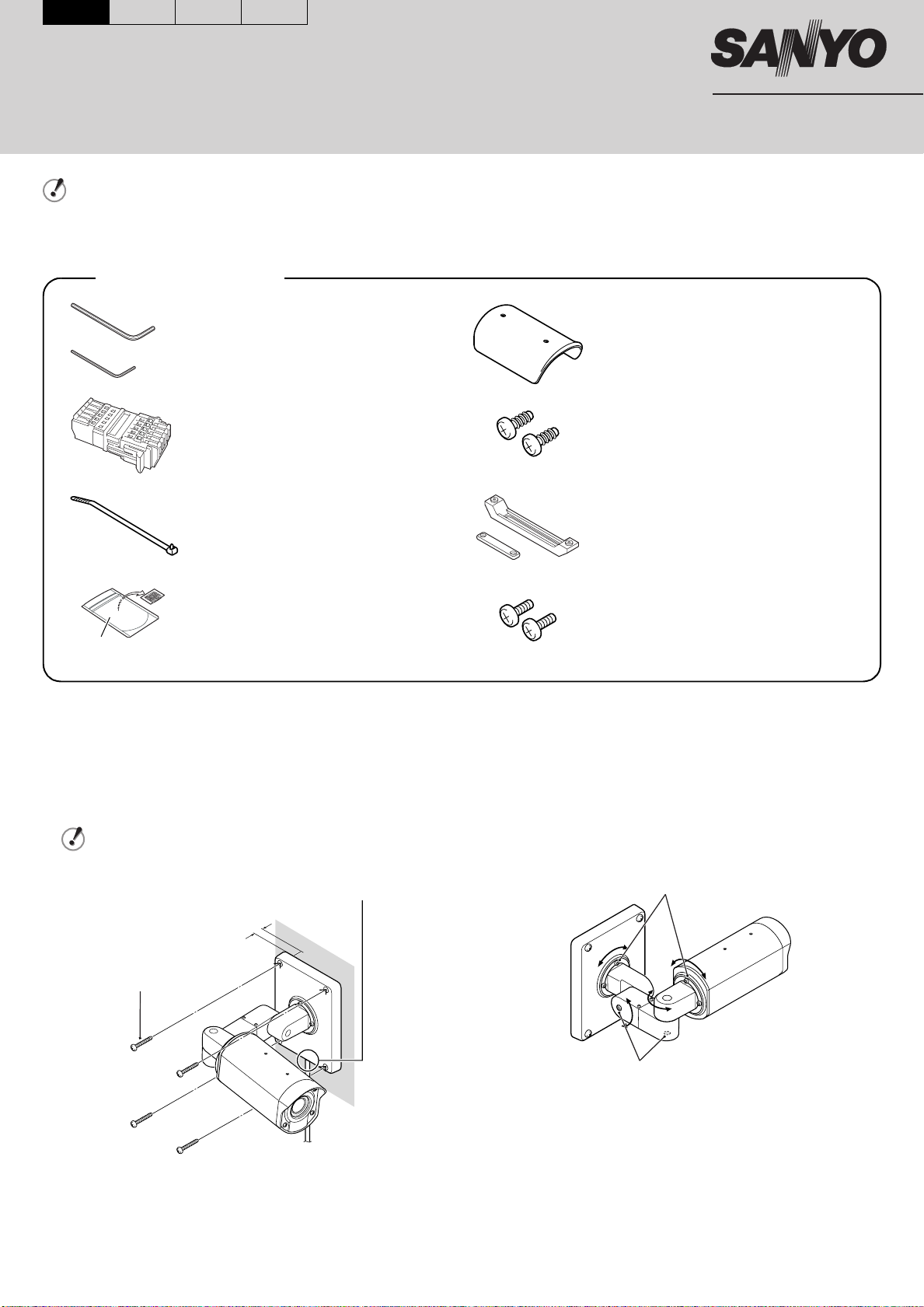
Accessories
Hexagonal wrench,
Large and Small. . . . . . . . . . . . . . .each 1
Sunshade . . . . . . . . . . . . . . . . . . . . . . . . 1
VCC-XZ200P
One-touch connector
(attached to connection cord). . . . . . . . . 1
Fixer
(for securing drop-prevention chain) . . . 1
Desiccant . . . . . . . . . . . . . . . . . . . . . . . . 1
Foil pouch
1 Setup
1 Install the camera to the wall or ceiling.
If routing the connection cord outside the wall, install so that
the connection cord hole is facing downward, and pull the
connection cord out from the hole.
Be sure to embed the mounting screws at least 3 cm into
the wall. If the screw holes are too shallow, the camera
mount may fall down.
Connection cord hole
Sunshade mounting screws
(Self-tapping type) . . . . . . . . . . . . . . . . . 2
Sunshade mounting bracket. . . . . . . . . . 1
Sunshade mounting bracket screws. . . . 2
2 Adjust the position of the camera.
Use the hexagonal wrench (large, accessory) to loosen the
screws at the place that you want to move, and then adjust
the direction of the camera.
After making the adjustment, securely re-tighten the screws.
Maximum 90 degrees
(to prevent cord from twisting)
Screw tightening torque after adjustment:
2 N.m or more
3 cm or more in
Mounting screw: M8
Screw tightening torque after adjustment:
4.3 N.m or more
Printed on recycled paper
1AC6P1P3050-L5BJ2/XE (0306KP-SY) Printed in Japan
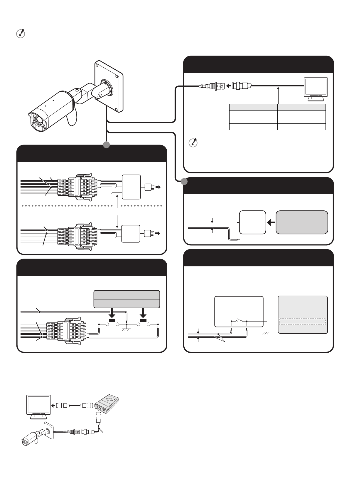
2 Connections
• Do not connect the power cord until all other connections have been completed.
• If part of the copper section of a wire is exposed after a cord has been connected, trim the end of the wire so that no
copper section is exposed in order to prevent short-circuits.
Connection for Monitoring
BNC type
Cable type Length
RG-59U (3C-2V) 250 m max.
RG-6U (5C-2V) 500 m max.
RG-11U (7C-2V) 600 m max.
=
• When using an RG-59U (3C-2V) cable, do not let it dangle
in the air or attach it to piping.
Connection for Power Supply
AC 24 V connection
White
Red
Brown/Black
DC 12 V connection
Check that polarity is correct.
Red
White
18 AWG or more
~
~
GND
+
–
• If you use a cable other than the types above, the image or
sync signal will be attenuated and will not be transmitted
correctly.
Connection for Alarm Input
Refer to the instruction manual for the connected alarm device for
further details.
Blue
Brown
Alarm
device
Common
External Alarm
Input Signal
Connection for Zoom Input
It is used to make wide angle/telescoping adjustments.
Zoom Input Signal
Brown
Ye ll o w
Orange
TELE WIDE
Common
■ Using a Camera Control Unit
When using menus, connect a camera control unit (VAC-70: Separately
ordered) because menu settings can be carried out without removing the
camera cover.
VAC -70
Setting Color or Black-and-White
You can fix the image either to color or black-and-white using an
external switch, etc.
• Be sure to select “COLOR” for the “DAY/NIGHT” option in the
main menu (See page 23 on the INSTRUCTION MANUAL).
External switch
Open: Color
Close: B/W
Gray/Black
Common
Brown 24 AWG: 600 m max.
SYNC
BLC
IRIS
WHITE BALANCE
AGC GAIN
GAMMA
SHUTTER
APERTURE
·DAY/NIGHT
OPTION
PRESET
MENU
INT
OFF
SET y
ATW
NORM
0.45
50
NORM
COLOR
SET y
OFF
END
RG-6U (5C-2V) cable,
BNC type
500 m max.
Note: Make sure to disconnect the unit after setting or adjustment is
completed.

3 Checking the image from the camera
Do not touch the lens and lens tube:
The lens and lens tube are composed of precision parts
that must be strictly kept untouched.
1 Remove the camera cover.
Loosen the four camera cover fixing screws.
2 Check the image on the monitor.
Ground
MONITOR
OUT
MONITOR OUT
Camera cover fixing
screws
To display an image simply on the
monitor, connect the MONITOR
OUT pin and ground on the circuit
board to the monitor using an
alligator clip cable.
Alternatively, you can connect the
MONITOR OUT terminal to the
monitor using the special purpose
connector.
• Positioning of the camera
Refer to 1 - 2.
• Simple zoom adjustment
While the camera captures an image, you can adjust
Zoom using the button (d: Wide or c: Tele) on the circuit
board.
3 Carry out the settings and adjustment for the camera
using the on-screen menu.
Refer to the separate-volume instruction manual.
4 Install the camera cover.
Provisionally tighten the four camera cover fixing screws, and
then fully tighten them.
The four camera cover fixing screws must be torqued to
0.5 – 1 N·m (5 – 10 kgf·cm/4.4 – 8.8 in·lbs) to ensure that
the waterproof integrity is maintained.
4 Attaching the fixer (accessory)
If you do not want the drop-prevention chain to hang down, move the camera to the required position and then secure the chain with the
fixer (accessory) as shown in the illustration below.
Drop-prevention chain
Press the tab on the
fixer as shown at
right to release it.
Fixer (accessory)
5 Installing the sunshade (accessory)
If direct sunlight may shine onto the camera at times (depending on the angle of the sun), install the sunshade.
1 Use the two accessory screws to install the sunshade
mounting bracket (accessory).
Determine the position of the sunshade so that it will protect
from direct sunlight as much as possible, and adjust the
position of the sunshade mounting bracket back and forth
while the screws are still loose (adjustment range: 30 mm).
After adjusting the bracket position, securely tighten the
screws. (Tightening torque: 0.5 N·m or more)
2 Use the two accessory screws (self-tapping type) to
install the sunshade (accessory). (Tightening torque: 0.5
N·m or more)
Self-tapping
screw for
plastic

Replacing the desiccant (accessory)
There is a pouch of desiccant (blue) inside the camera to prevent moisture from
building up inside the camera. If the desiccant appears reddish-purple after the
camera cover is removed, remove the camera unit and replace it with the new pouch
of desiccant (consult your dealer or a Sanyo Authorized Service Center).
Desiccant
■ Removing the camera unit
• To avoid damaging the camera and the power supply, always be sure to turn off the power.
• Be careful to avoid letting it get wet from rain or other liquids, otherwise it may become shorted.
• The camera cover will come off if the camera cover fixing screws are loosened by about 5 mm, so be careful not to loosen them
too much. If a screw is loosened too much, the drop-prevention washer inside the cover may come off and the screw may fall out.
1 Loosen the four camera cover fixing screws, and then remove
the camera cover.
2 Use the hexagonal wrench (small, accessory) to loosen the
camera fixing screw, and then remove the camera unit.
Do not touch the lens and lens tube:
The lens and lens tube are composed of precision parts
that must be strictly kept untouched.
• Loosen the camera fixing screw until
the L-shaped camera fixing bracket
comes away from the camera fixing
base, and then slide the camera in
the direction of the arrow shown
above and then lift it up.
• Always be sure to turn the
hexagonal wrench horizontally to
avoid damaging the circuit board.
Hexagonal wrench
(small, accessory)
L-shaped camera fixing bracket
3 Install the camera by using the hexagonal wrench (small,
accessory) to tighten the camera fixing screw.
Tighten the screw so that the head protrudes by 0 – 0.5 mm.
Hexagonal wrench
(small, accessory)
0 – 0.5 mm
L-shaped camera fixing bracket
4 To install the camera cover, provisionally tighten the four
camera cover fixing screws, and then fully tighten them.
The four camera cover fixing screws must be torqued to
0.5 – 1 N·m (5 – 10 kgf·cm/4.4 – 8.8 in·lbs) to ensure that
the waterproof integrity is maintained.
Camera fixing base
 Loading...