

Page 1
INSTRUCTION MANUAL
VCC-9400P
Dome type camera
D
F
English GB
CS
About this manual
Before installing and using the camera, please read this
manual carefully. Be sure to keep it handy for later
reference.
Page 2
PRECAUTIONS
CONTENTS
In case of problem
Do not use the camera if smoke or a strange odour comes from the
unit, or if it seems not to function correctly. Disconnect the power
cord immediately, and consult your dealer (or a Sanyo Authorized
Service Centre).
Do not open or modify
Do not open the cabinet, as it may be dangerous and cause
damage to the unit. For internal settings and repairs, consult your
dealer (or a Sanyo Authorized Service Centre).
Do not put objects inside the unit
Make sure that no metal objects or flammable substance get inside
the camera. If used with a foreign object inside, it could cause a
fire, short-circuits or damages.
If water or a liquid gets inside the camera, disconnect the power
cord immediately, and consult your dealer (or a Sanyo Authorized
Service Centre). Be careful to protect the camera from rain, sea
water, etc.
Be careful when handling the unit
To prevent damages, do not drop the camera or subject it to strong
shock or vibration.
Install away from electric or magnetic fields
If installed close to a TV, radio transmitter, magnet, electric motor,
transformer, audio speakers the magnetic field they generate will
distort the image.
Protect from humidity and dust
To prevent damages to the camera, do not install it where there is
greasy smoke or steam, where the dampness may get too high, or
where there is a lot of dust.
Protect from high temperatures
Do not install close to stoves, or other heat generating devices,
such as spotlights, etc., or where it could be subject to direct
sunlight, as that could cause deformation, discoloration or other
damages.
Be careful when installing close to the ceiling, in a kitchen or boiler
room, as the temperature may raise to high levels.
Install where the temperature range will stay between –10°C and
50°C. (no condensation)
Cleaning
Dirt can be removed from the cabinet by wiping it with a soft
•
cloth. To remove stains, wipe with a soft cloth moistened with a
soft detergent solution and wrung dry, then wipe dry with dry
soft cloth.
Do not use benzine, thinner or other chemical product on the
•
cabinet, as that may cause deformation and paint peeling.
Before using a chemical cloth, make sure to read all
accompanying instructions. Make sure that no plastic or rubber
material comes in contact with the cabinet for a long period of
time, as that may cause damage or paint peeling.
MAIN FEATURES . . . . . . . . . . . . . . . . . . . . . . . . . . . . . . . 2
ACCESSORIES . . . . . . . . . . . . . . . . . . . . . . . . . . . . . . . . . 2
PART NAMES . . . . . . . . . . . . . . . . . . . . . . . . . . . . . . . . . . 3
INSTALLATION METHOD . . . . . . . . . . . . . . . . . . . . . . . . 4
CONNECTIONS. . . . . . . . . . . . . . . . . . . . . . . . . . . . . . . . . 5
Basic connections (RS485). . . . . . . . . . . . . . . . . . . . . . .
System control connections. . . . . . . . . . . . . . . . . . . . . .
BASIC OPERATIONS . . . . . . . . . . . . . . . . . . . . . . . . . . . . 7
MENU ITEM FLOW AND MENU OPERATION . . . . . . . . 8
Menu item flow. . . . . . . . . . . . . . . . . . . . . . . . . . . . . . . . .
LANGUAGE SETTING . . . . . . . . . . . . . . . . . . . . . . . . . . . 9
PRESET POSITION SETTINGS . . . . . . . . . . . . . . . . . . . . 10
PRESET POSITION item flow . . . . . . . . . . . . . . . . . . . . .
Preset position settings (PRESET NO.) . . . . . . . . . . . . .
A
Deleting preset positions (DELETE) . . . . . . . . . . . . . . .
B
The Camera ID and TITLE setting screen . . . . . . . . . . .
C
CAMERA VIEW setting . . . . . . . . . . . . . . . . . . . . . . . . . .
D
PAUSE TIME settings . . . . . . . . . . . . . . . . . . . . . . . . . . .
E
10
11
11
12
13
13
CAMERA SETTINGS . . . . . . . . . . . . . . . . . . . . . . . . . . . . 14
CAMERA SETTING item flow . . . . . . . . . . . . . . . . . . . . .
SYNC setting . . . . . . . . . . . . . . . . . . . . . . . . . . . . . . . . . .
A
PRIVACY MASK setting. . . . . . . . . . . . . . . . . . . . . . . . . .
B
LENS setting item flow . . . . . . . . . . . . . . . . . . . . . . . . . .
C
FOCUS setting . . . . . . . . . . . . . . . . . . . . . . . . . . . . . .
A
ZOOM setting . . . . . . . . . . . . . . . . . . . . . . . . . . . . . . .
B
DAY/NIGHT setting . . . . . . . . . . . . . . . . . . . . . . . . . . .
C
VIEW ANGLE setting . . . . . . . . . . . . . . . . . . . . . . . . .
D
VIEW SETTING item flow. . . . . . . . . . . . . . . . . . . . . . . . .
D
IRIS setting . . . . . . . . . . . . . . . . . . . . . . . . . . . . . . . . .
A
WHITE BALANCE adjustment . . . . . . . . . . . . . . . . . .
B
Electronic SHUTTER setting . . . . . . . . . . . . . . . . . . .
C
MOTION detector setting . . . . . . . . . . . . . . . . . . . . . .
D
Profile compensation setting (APERTURE) . . . . . . .
E
GAMMA correction setting . . . . . . . . . . . . . . . . . . . .
F
14
15
15
18
19
21
22
26
27
28
32
35
36
39
39
AUTO MODE SETTINGS . . . . . . . . . . . . . . . . . . . . . . . . . 40
AUTO MODE item flow . . . . . . . . . . . . . . . . . . . . . . . . . .
Sequential pan setting. . . . . . . . . . . . . . . . . . . . . . . . . . .
A
Tour mode setting . . . . . . . . . . . . . . . . . . . . . . . . . . . . . .
B
Auto pan setting. . . . . . . . . . . . . . . . . . . . . . . . . . . . . . . .
C
40
41
41
42
AUTO FLIP SETTING . . . . . . . . . . . . . . . . . . . . . . . . . . . . 44
ALARM SETTING . . . . . . . . . . . . . . . . . . . . . . . . . . . . . . . 45
ALARM item flow . . . . . . . . . . . . . . . . . . . . . . . . . . . . . . .
Alarm input setting . . . . . . . . . . . . . . . . . . . . . . . . . . . . .
A
Alarm output setting . . . . . . . . . . . . . . . . . . . . . . . . . . . .
B
45
46
47
FREEZE AND REFRESH SETTINGS. . . . . . . . . . . . . . . . 48
FREEZE setting . . . . . . . . . . . . . . . . . . . . . . . . . . . . . . . .
REFRESH setting . . . . . . . . . . . . . . . . . . . . . . . . . . . . . . .
48
48
STARTING POINT (0 DEGREES) ANGLE SETTING . . . 49
ADDRESS SETTINGS TABLE . . . . . . . . . . . . . . . . . . . . . 50
SPECIFICATIONS. . . . . . . . . . . . . . . . . . . . . . . . . . . . . . . 51
5
6
8
English
– 1 –
Page 3
MAIN FEATURES
Pan, tilt and zoom operations as well as focus and iris settings
•
can be done manually.
Up to 64 preset positions can be set to store zoom and focus
•
data for corresponding surveillance locations.
Surveillance can be set up for automatic successive display of
•
the locations established by the preset positions.
(SEQUENTIAL PAN) In addition, each of the preset positions
can be customized with 9 different camera settings. (VIEW
SETTING)
Automatic loop panning can be set after establishing start and
•
end locations. (AUTO PAN)
Manual pan, tilt and zoom operations can be saved in an image
•
track (30 or 60 seconds), and the image track can be used to
automatically repeat the set of camera operations. (TOUR
MODE)
For operations in which the camera is tilted beyond the straight
•
down position, automatic top/bottom or left/right inversion of the
image can be set for upright viewing of the image throughout
180 degrees of camera tilt. (DIGITAL AUTOFLIP)
A cleaning function keeps horizontal rotation of the camera unit
•
in smooth working order. (REFRESH)
Nine different items can be set for camera surveillance
•
conditions, such as white balance, iris and motion sensing.
These set conditions are applied separately for each preset
position when sequential pan is activated.
Gray-colored masking patterns can be placed over defined
•
areas to protect privacy. (PRIVACY MASK)
One-push automatic white balance is available to adjust the
•
image in surveillance locations where faithful color reproduction
is difficult.
Backlight compensation can be set to one of three different
•
methods: multi-spot evaluative metering, 5 spot centerweighted
average metering or 48 multi-spot metering.
The monitor screen can be divided into 48 zones and based on
•
image information for each zone, target objects for such images
as intruder movements can be discerned and an alarm
generated.
The Day/Night function is a function that can adapt to a wide
•
range of changing luminance levels by automatically switching
to color during daytime, or to black and white at times of low
luminance such as nighttime.
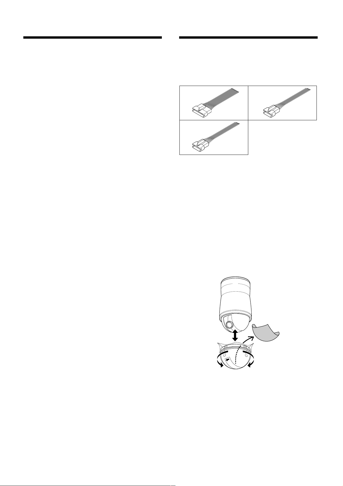
ACCESSORIES
Alarm input expansion connector (10 pin) . . . . . . . . . . . . . . 1
1
Camera control expansion connector (5 pin) . . . . . . . . . . . . 1
2
Alarm output expansion connector (5 pin) . . . . . . . . . . . . . . 1
3
13
2
Before installation
A protective wrapper has been placed on the outside of the dome
cover and a protective sheet on the inside of the cover. Before
installing the unit, be sure to remove the wrapper and sheet as
described in the steps below.
1
With the exterior cover wrapper still in place, turn the cover to
the left from its fastened position (cover lock position) and
remove it from the unit.
2
Take the protective sheet out of the interior of the dome cover.
3
Confirm that the gasket on the dome cover has the proper gap,
then line up the 4 tabs on the dome cover with the 4 slots on the
inside of the dome camera unit and push the dome cover in
completely.
4
Lock the dome cover in place by turning it to the right (cover
lock position).
– 2 –
English
Page 4
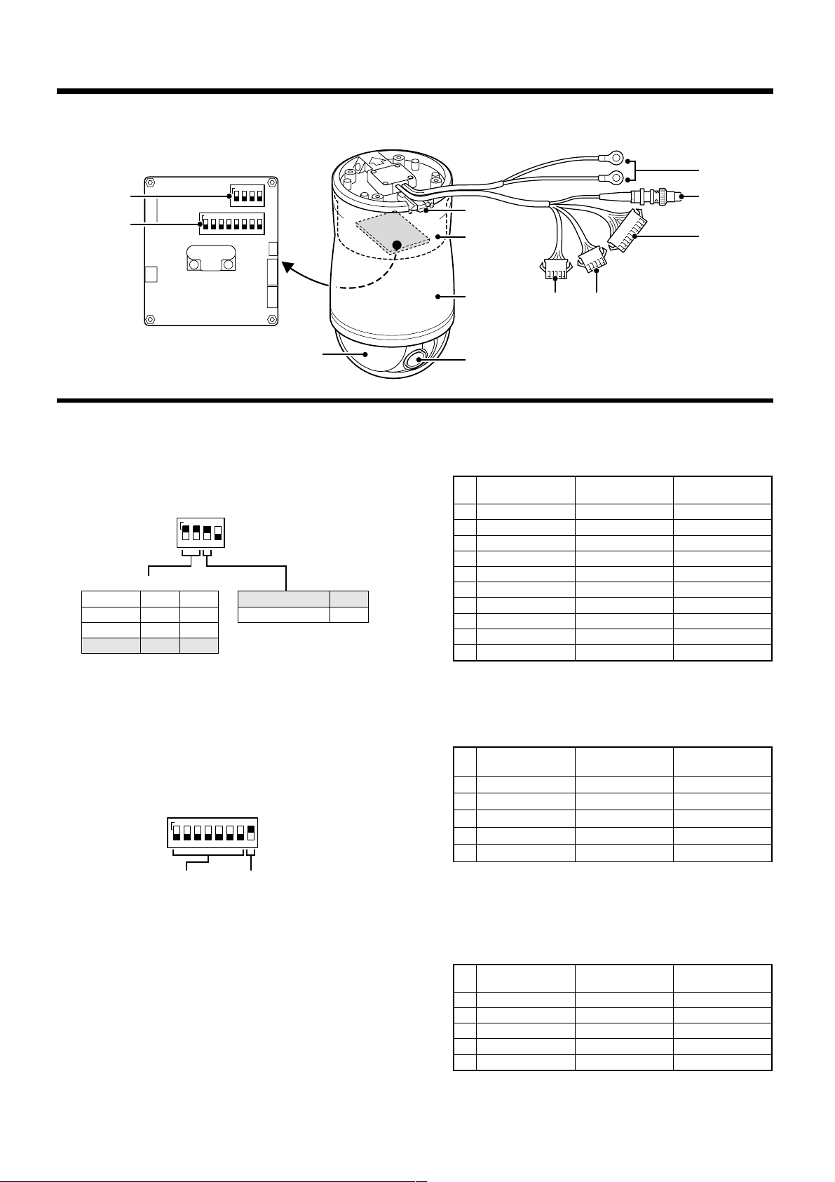
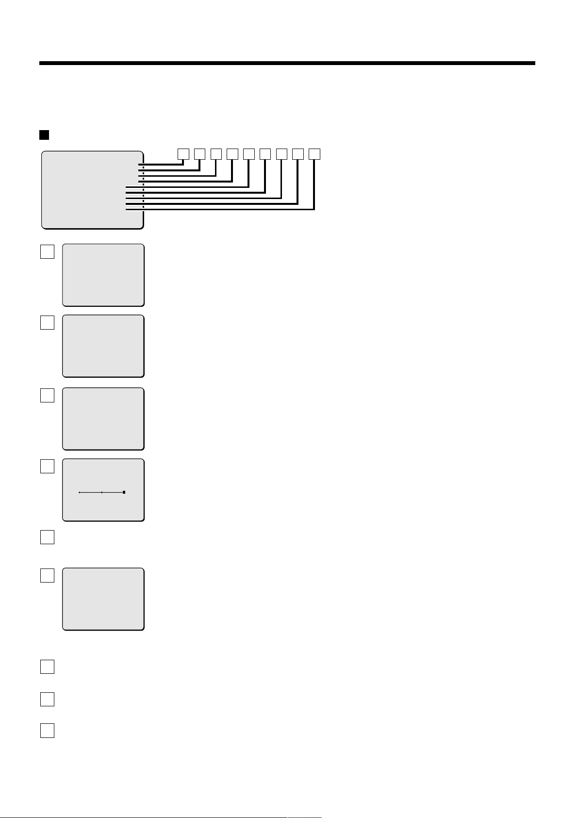
PART NAMES
1
2
ON
1234
ON
12345678
3
4
8
9
F
7
System control setting switches (See p4)
1
Sets baud rate and sets RS485 or coaxial control.
•
Baud rate setting
Initial setting is 19200bps.
•
RS485 or coaxial control setting
Initial setting is coaxial control.
ON
1234
Baud rate (bps)
OFF
2400
4800
9600
19200
Address setting switches (See p4)
2
The address of the camera set here is needed for operating the
camera through a system controller. In addition, when the
camera is connected to the system, be sure to set the terminate
setting to ON when the camera is in the last connected position.
•
Address setting (See p50)
Address values can be between 0 and 127.
Initial setting is for all switches OFF.
•
Terminate setting
Initial setting is ON.
OFF
ON
OFF
OFF
ON
ON
ON
ON
1234567 8
Coaxial control
RS485
ON
OFF
5
HG
6
Alarm input connector (10 pin)
F
Use for functions such as intruder detection. Connect the
supplied alarm input expansion connector to this connector and
install the alarm detection switch on the cable side.
Colour
1 Alarm input 1 Orange/Black Brown
2 Alarm input 2 Yellow/Black Red
3 Alarm input 3 Green/Black Orange
4 Alarm input 4 Gray/Black Yellow
5 GND White/Gray Green
6 Alarm input 5 Black Blue
7 Alarm input 6 Blue Lilac
8 Alarm input 7 Lilac Gray
9 Alarm input 8 Brown White
10 GND Red Black
Alarm output connector (5 pin, white)
G
Use for controlling peripheral equipment or supplying power to
sensors and other devices. Connect the supplied alarm output
expansion connector to this connector and use to establish
output to the cable side of the connection.
Colour
1 Alarm output 1 Lime Brown
2 Alarm output 2 Pink Red
3 GND Sky-Blue Orange
4 N. C Brown/Black Yellow
5 GND Red/Black Green
Colour
(accessory)
Colour
(accessory)
Address setting Terminate setting
Power supply unit removal lever
3
This lever is be used to remove the power supply from the
camera unit when switch settings need to be made.
(See p4)
Power supply unit
4
Camera unit
5
Lens
6
Dome cover
7
Power supply cable (AC 24 V, 50Hz)
8
Video output connector (BNC)
9
English
– 3 –
* Open collector output, drive capacity up to 18 V, 50 mA.
Camera control connector (5 pin, black)
H
Connect this line when controlling the camera by RS485.
Connect the supplied camera control expansion connector to
this connector and connect peripheral equipment such as a
system controller to the cable.
Colour
1A (+) Orange Brown
2 B (–) Yellow Red
3 A (+) Green Orange
4 B (–) Gray Yellow
5 GND White Green
Colour
(accessory)
Page 5
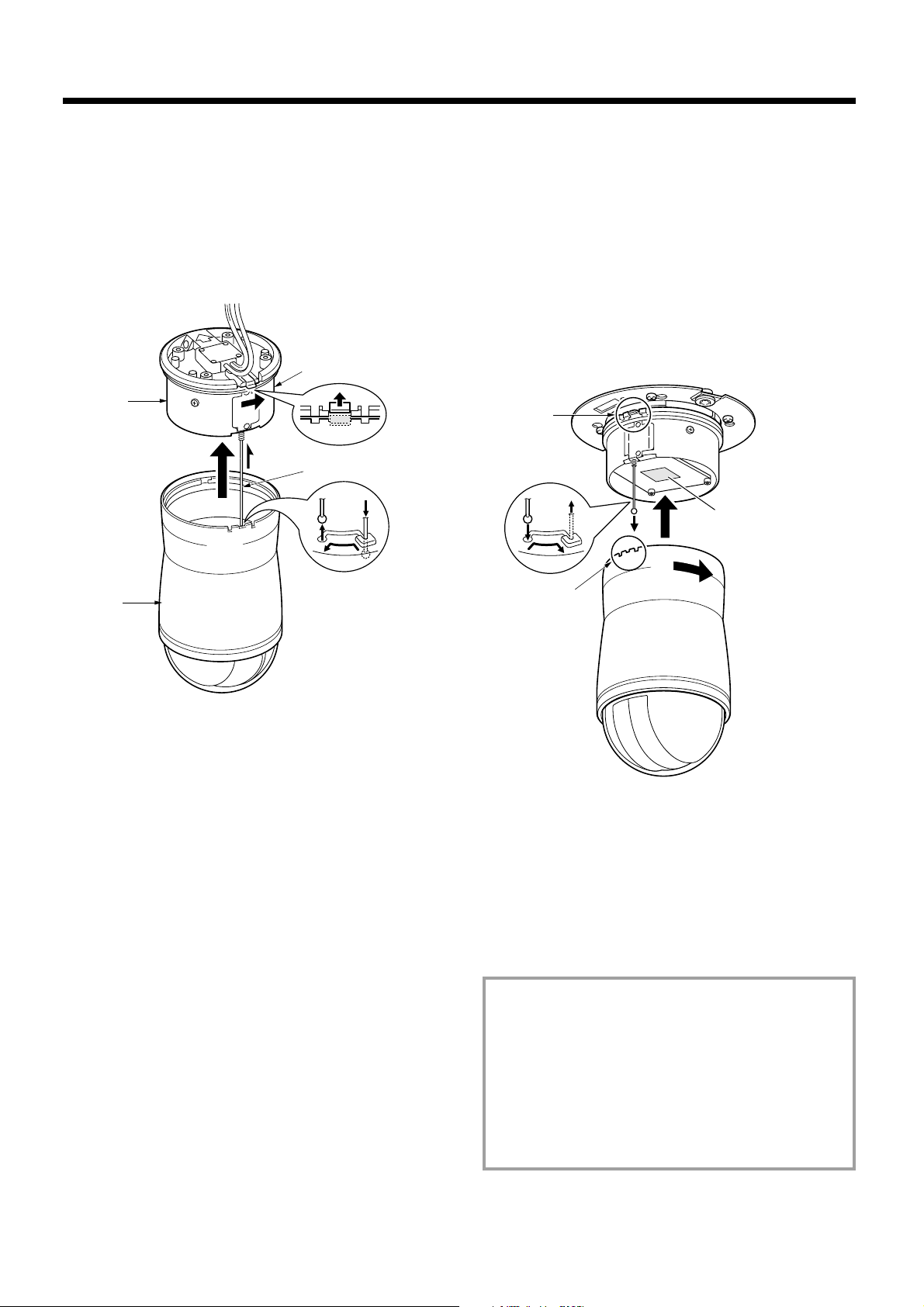
INSTALLATION METHOD
1
Power supply unit removal
1 Press in the power supply unit removal lever (A) until it
clicks, then turn the power supply unit (C) in the direction
of the arrow and pull it away from the camera unit (B).
2 Gently push the safety wire (D) into its holding slot and
move it in the direction of the arrow until it can be
removed. This is done to help the installation go smoothly.
A
C
D
B
3
Attach the camera unit to the power supply unit
Match the camera unit alignment notches (F) with the power
supply unit lever slot (G), then turn the camera unit in the
direction of the arrow.
A clicking sound will be heard when the power supply unit
removal lever drops into place, indicating that the camera unit
is properly set.
Note:
The camera unit is not properly set if a clicking sound is not
•
heard. Check that the unit is firmly set.
Do not continue to turn the camera unit after it has been
•
properly set. Doing so could damage the camera.
F
E
Settings circuit board
G
2
If the safety wire has been removed, take the safety wire
stowed in the power supply unit and attach it to the
camera unit.
Reversing the safety wire removal procedure, reliably reattach
the safety wire. (E)
Consumable items:
The following parts are consumable items, so please replace
them after their worklife has expired. Moreover, component
performance cannot be guaranteed when parts are used to the
very end of their projected worklife. Durability will differ
according to environmental conditions and usage.
Lens: about 20,000 hours (1,200,000 operations)
•
Slip Ring: about 20,000 hours (1,200,000 rotations)
•
Motor: about 33,000 hours (12,000,000 revolutions)
•
Fan: 30,000 hours
•
– 4 –
English
Page 6
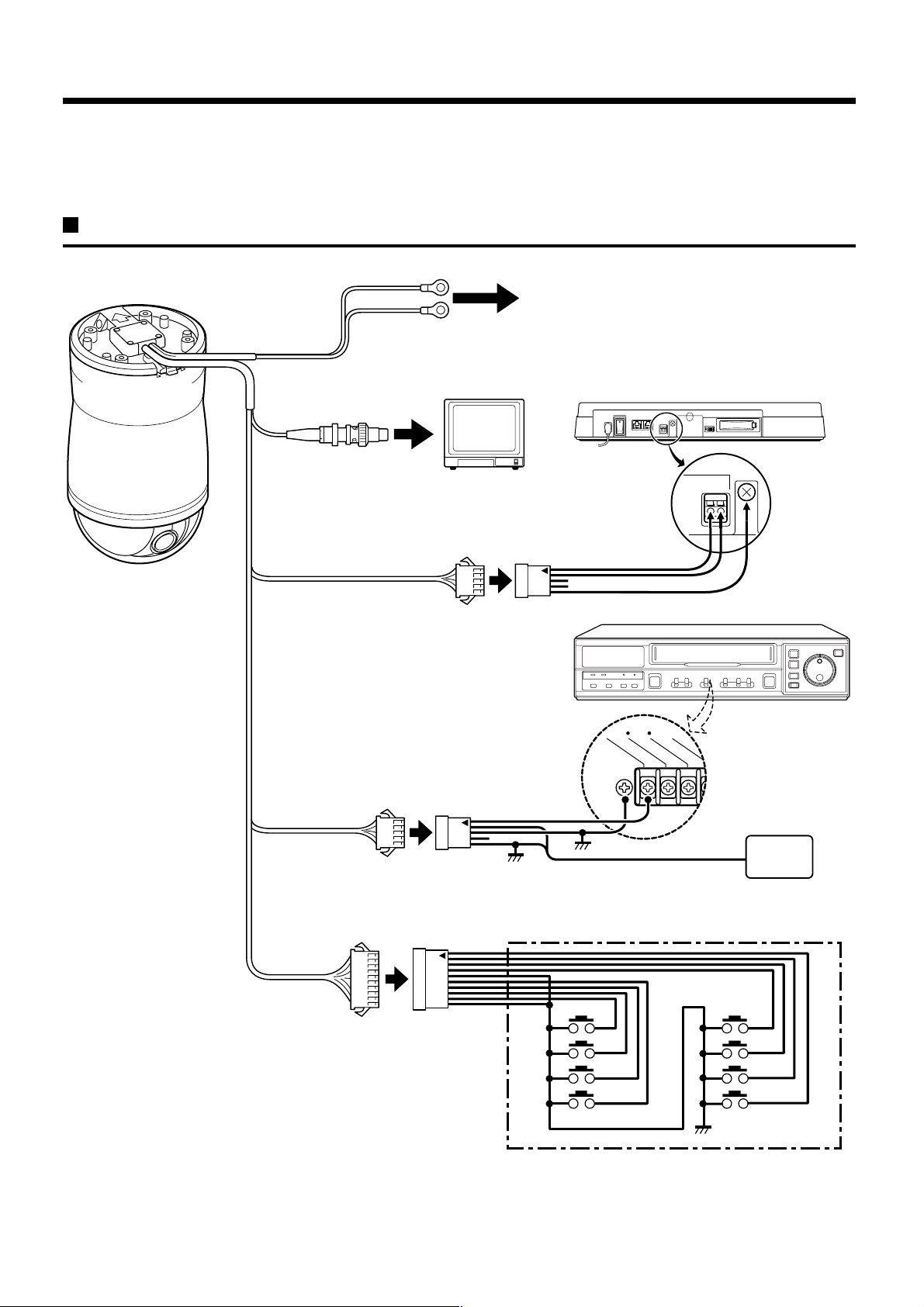
CONNECTIONS
EXT TIM
ER IN
SERIES IN
CONTROL IN
ALARM(1 SHOT) IN
(ALARM RESET
Turn off the power for all components before connecting them.
Be sure to carefully read the Instruction Manual for all equipment being connected to the camera.
If the connections are incorrect, smoke or operating malfunctions may result.
Basic connections (RS485)
Power supply cable (AC 24 V, 50 Hz)
To AC 24 V
Video output connector (BNC)
Camera control
connector (5 pin)
✱ Pin 1 is shown by the arrow
Alarm output
connector (5 pin)
TV monitor
(sold separately)
Camera control expansion
connector (5 pin)
(✱)
Alarm output expansion
connector (5 pin)
(✱)
System controller
(sold separately)
RS485
Digital video recorder (sold separately)
AB
GND
Buzzer or lamp
Alarm input
connector (10 pin)
Connecting external alarm sensors
To enable external alarm sensors, connect the supplied alarm input
expansion connector to the alarm input connector, then connect external
switches to suitable lead wires of the expansion connector. When an
intruder triggers the external switch (such as opening and closing a door),
the alarm signal is received and an alarm sounds. See the alarm setting
section for details. (See p45)
English
Alarm input expansion
connector (10 pin)
(✱)
– 5 –
Connect an external switch
to an ALARM IN connector
Page 7
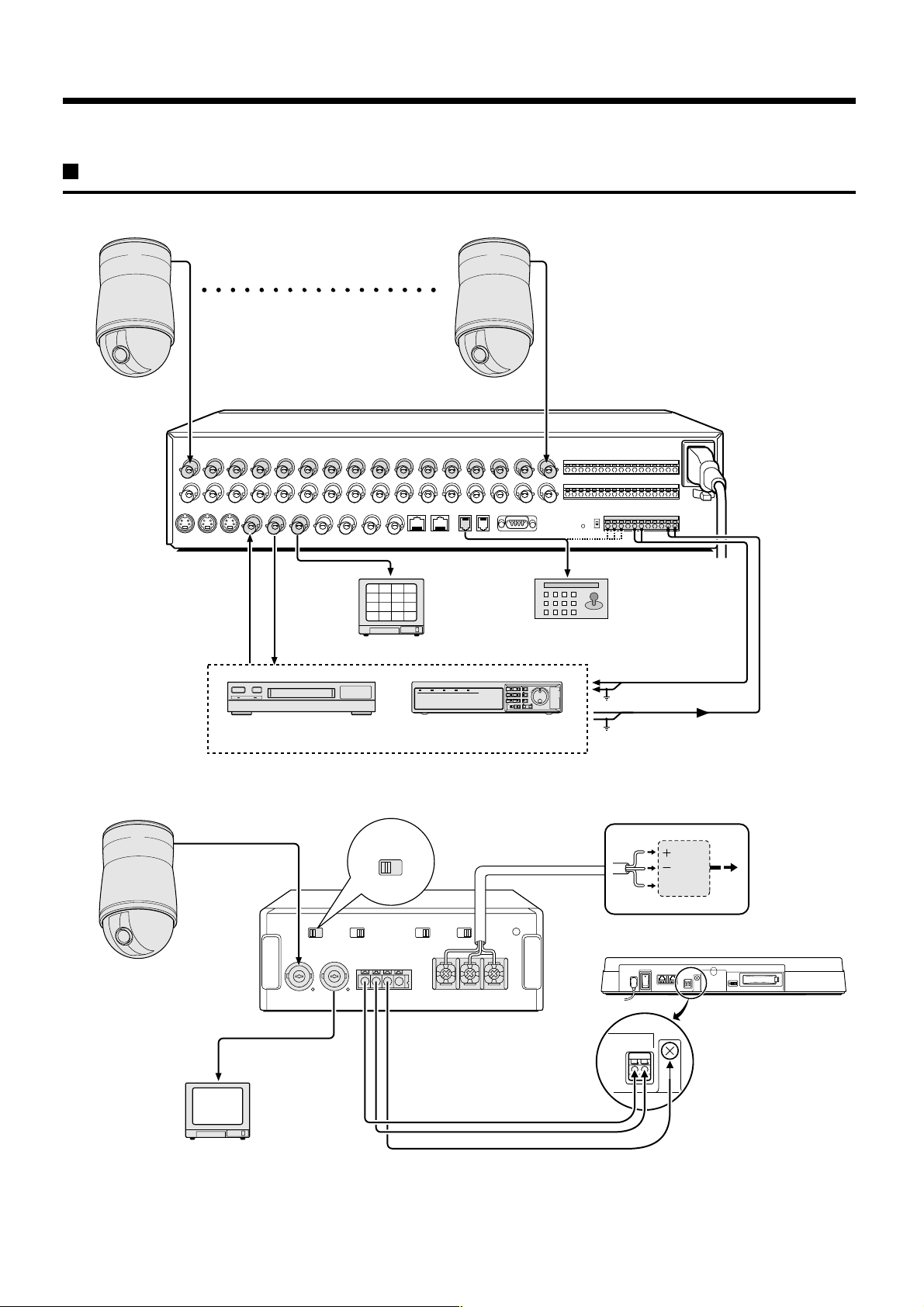
CONNECTIONS
System control connections
Example 1: Coaxial control system connection (1)
1 – 16
Video output
connector (BNC)
SSP (RS-485) single-type multiplexer (sold separately)
Time lapse VCR
(sold separately)
2
1
3
4
6
5
7
8
10
9
11
12
14
13
15
16
TV monitor (sold separately)
or
Digital video recorder
(sold separately)
Video output
connector (BNC)
RS-485 connector
System controller
(sold separately)
ALARM IN connector
Ground (C)
Ground (C)
Switch output connector
Example 2: Coaxial control system connection (2)
Video output
connector (BNC)
Video input
connector
TV monitor (sold separately)
CONTROL SIGNAL
SEPAMIX
COAX-SSP converter
(sold separately)
– 6 –
24V AC
GND
System controller (sold separately)
RS485
GND
AB
English
Page 8
BASIC OPERATIONS
Use the following settings and connections to operate this camera with a system controller (sold separately) .
1
Make connections with all equipment turned
off.
2
After referring to “INSTALLATION METHOD”
Step 3, remove the power supply unit and set
the dip switches on the camera’s circuit
board. (See p4)
Terminate setting (System control setting
switches):
Initial setting is ON. When several cameras are
connected together, the last camera in the series
should be set to ON and the other cameras set to
OFF.
(System controller settings):
Set the TERMINATE position (ON/OFF) of the
“ADDRESS/TERMINATE” dip switches on the back
panel.
Baud rate (System control setting switches):
Initial setting is 19200bps. To set a different baud
rate, change the switches to the appropriate settings.
(System controller settings):
Set the baud rate at the “BAUD RATE SET” item on
the menu screen.
Note: Be sure the controller and the camera are set to the
same baud rate.
4
Operation of the camera with the system
controller
Operation methods are described below. For detailed
information about operation, see the instruction manual
of the system controller.
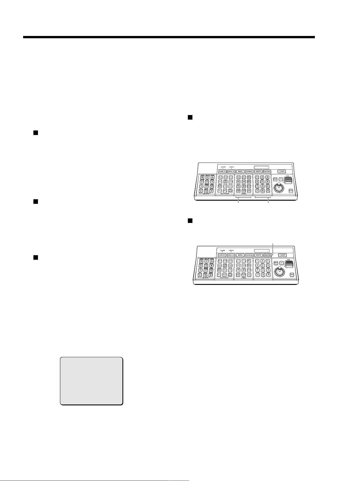
Type of camera operation with the system
controller
Direct input from “CAMERA” keypad buttons.
This operation makes needed adjustments to the
camera’s basic settings according to photographic
factors such as light compensation and shutter
speed.
“CAMERA” keypad
camera commands
The FUNCTION button on the system controller
enables selection a command from 5 types of
call-up commands.
Numeric keypad
FUNCTION button
Address setting (Address setting switches):
Initial setting is all switches to “0”. The address can
be set from 0 to 127. To set an address, refer to
“ADDRESS SETTING TABLE” and then move the
switches. (See p50)
(System controller settings):
Set the ADDRESS position (1 – 3) of the
“ADDRESS/TERMINATE” dip switches on the back
panel.
3
Install the power supply unit and turn on
power to all equipment.
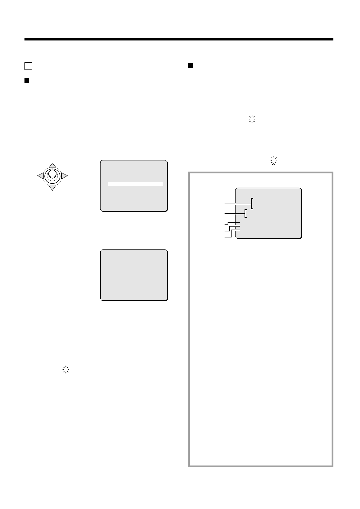
When the power is turned on, the camera will perform
its startup movements. The camera’s address will flash
on the monitor screen.
CAMERA ADDRESS
001
(Example)
(Call-up commands)
ALARM OUT
•
ZOOM PRESET
•
PRESET MEMORY
•
Note:
Group operation enables setting and operation of groups
•
1 –- 15. Do not use group 0 (ALL) or category “ALL”.
When a magnification power is set for the electronic sensitivity,
•
it can also be adjusted with the “ELS” button on the system
controller.
If SENSE UP and the electronic shutter are both OFF, pressing
•
the “ELS” button on the system controller will automatically set
electronic sensitivity boosting to “x8”.
L-L PHASE
•
RESET
•
English
– 7 –
Page 9
MENU ITEM FLOW AND MENU OPERATION
These menu items allow setting of autopan and sequential pan and other camera functions.
If these settings are not made, autopan and sequential pan cannot be utilized, so be sure to make settings appropriate to desired operations.
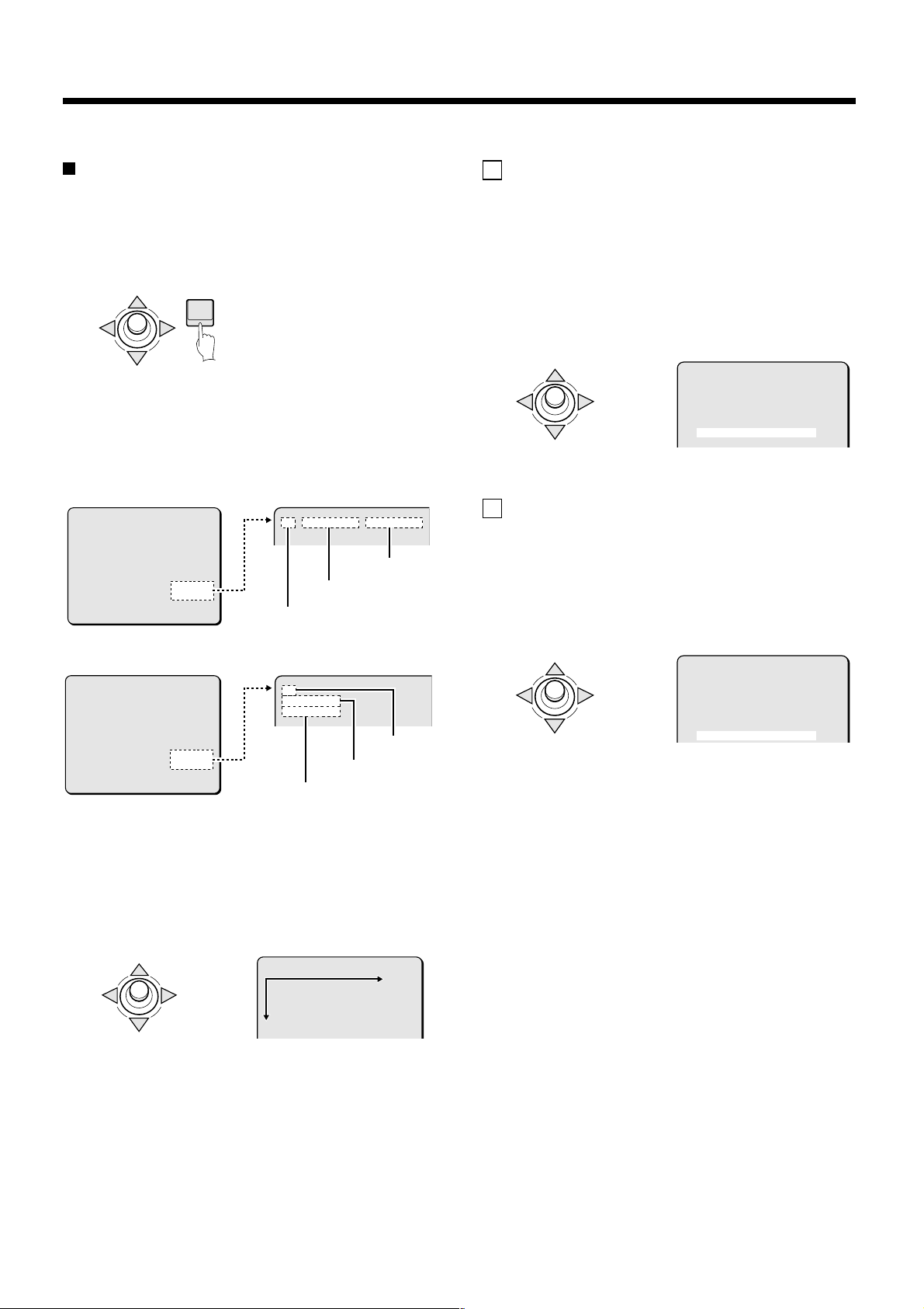
Menu item flow
1
MAIN MENU
LANGUAGE SET ‚
PRESET POSITION SET ‚
CAMERA SET ‚
AUTO MODE SEQ ‚
AUTO FLIP OFF
ALARM OFF
FREEZE OFF
REFRESH OFF
STARTING POINT OFF
MENU END
2 3 4 5 6 7 8 9
LANGUAGE
1
LANGUAGE ENGLISH
LANGUE FRENCH
SPRACHE GERMANY
MENU BACK
PRESET SETTING
2
PRESET NO. 2 ‚
DELETE SET ‚
TITLE OFF
CAMERA VIEW 1
PAUSE TIME 5S
MENU BACK
CAMERA SETTING
3
SYNC INT
PRIVACY MASK SET ‚
LENS SET ‚
VIEW SETTING 1 ‚
PRESET OFF
MENU BACK
SEQUENCE
4
ORDER STEP
PAUSE TIME 5S
[SEQ SPEED]
15
MENU BACK
LANGUAGE setting (See p9)
Choose from among English, French and German.
PRESET POSITION settings (See p10)
• Enables sequential automatic display of screen views by storing 64 surveillance locations.
• Enables display of a TITLE for screens.
• Sets 9 “VIEW SETTING” items for the camera.
• Sets the “PAUSE TIME” for surveillance positions when on sequential pan.
CAMERA settings (See p14)
• Sets SYNCH preference (power supply synchronization).
• Sets PRIVACY MASK for masking protection.
• Sets items related to the lens, such as zoom, focus and day/night settings.
• Sets 1 of 9 possible “VIEW SETTING” patterns for the camera.
AUTO MODE settings (See p40)
•
Sets ordering method for sequential automatic display by numeric order or random selection. (Sequential pan)
• Selects image tracking memory (30 seconds or 60 seconds). (Tour mode)
• Sets Auto pan movements between start point and end point. (Auto pan mode)
AUTO FLIP setting (See p44)
5
Enables automatic top/bottom or left/right inversion of the image for camera tilts beyond the straight down position, which allows
upright viewing of the image throughout 180 degrees of camera tilt. (DIGITAL AUTOFLIP)
ALARM
6
ALARM IN 1 ‚
MOVE MODE OFF
ALARM OUT OFF
PRESET OFF
MENU BACK
ALARM settings (See p45)
(Alarm input: 8 related items)
• Sets alarm input.
• Sets polarity at time of alarm input.
• Sets move to preset position at time of alarm input.
• Sets alarm to work with motion sensors and external alarms.
(Alarm output: 2 related items)
• Sets polarity for alarm external
output.
• Sets duration time of external alarm
output.
• Sets alarm output to the communications line.
• Sets alarm duration time.
• Sets alarm output.
FREEZE setting (See p48)
7
When using sequential pan this setting pauses the last image of a surveillance position before the camera shifts to a new position.
REFRESH setting (See p48)
8
Sets the cleaning of the camera’s horizontal rotation contact points.
STARTING POINT (0 degrees) angle setting (See p49)
9
Sets the position to 0 degrees angle. Angle information can be received by RS-232C.
– 8 –
English
Page 10
LANGUAGE SETTING
Select one of the languages shown on the menu screen (English,
French, German).
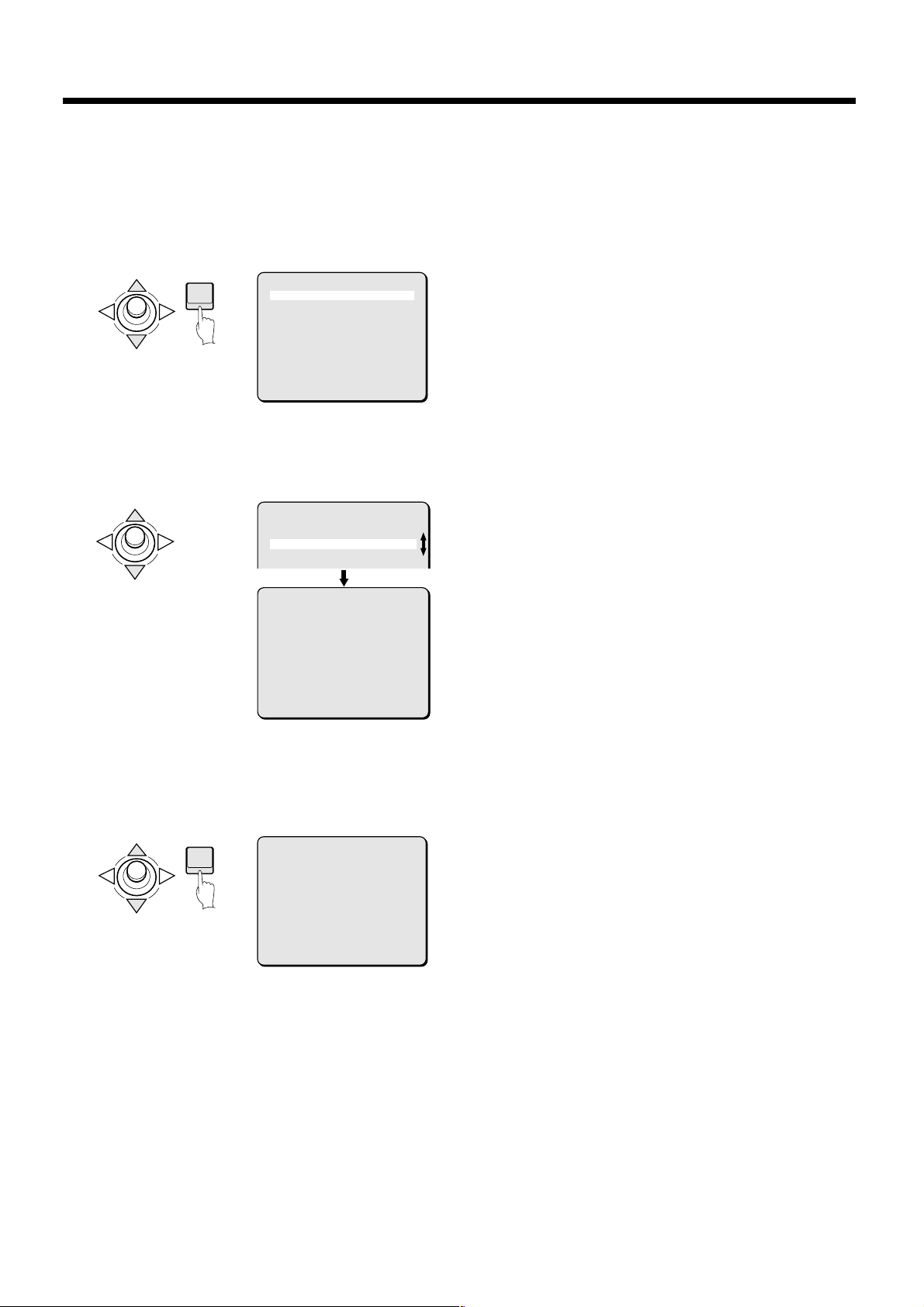
1
In the MAIN MENU, use the joystick lever (j or l) to
select SET for LANGUAGE, then press the ENTER button.
The LANGUAGE screen will appear.
ENTER
2
Use the joystick lever (j or l) to move the cursor to
MAIN MENU
LANGUAGE SET ‚
PRESET POSITION SET ‚
CAMERA SET ‚
AUTO MODE PAN ‚
AUTO FLIP OFF
ALARM OFF
FREEZE OFF
REFRESH OFF
STARTING POINT OFF
MENU END
language (example: “FRENCH”) then press the ENTER
button.
The interface language becomes French.
LANGUAGE
LANGUAGE ENGLISH
LANGUE FRENCH
SPRACHE GERMANY
LANGUE
LANGUAGE ANGLAIS
LANGUE FRANCAIS
SPRACHE ALLEMAND
MENU RETOUR
3
Use the joystick lever (j or l) to select RETUOR for
MENU, then press the ENTER button.
The MAIN MENU screen will reappear.
Information in the MAIN MENU screen will appear in the
selected language.
MENU PRINCIPAL
LANGUE REG ‚
PREREGLAGE REG ‚
CAMERA REG ‚
MODE AUTO SEQ ‚
INV AUTO ARR
ALARME ARR
GEL ARR
REAFFICHAGE ARR
POINT DE DEPART ARR
MENU FIN
4
Canceling a settings screen
ENTER
Use the joystick lever (l) to select FIN for MENU, then
press the ENTER button. The normal screen will reappear.
English
– 9 –
Page 11
PRESET POSITION SETTINGS
PRESET SETTING
SET
The PRESET POSITION function stores surveillance locations in memory. Up to 64 positions can be stored, and these surveillance locations
can be viewed in order by sequential automatic display. In addition, a title can be set for each of the stored surveillance locations and each
location can have a camera settings pattern assigned to it (from among 9 different patterns in the “VIEW SETTING (Camera settings)” menu
item).
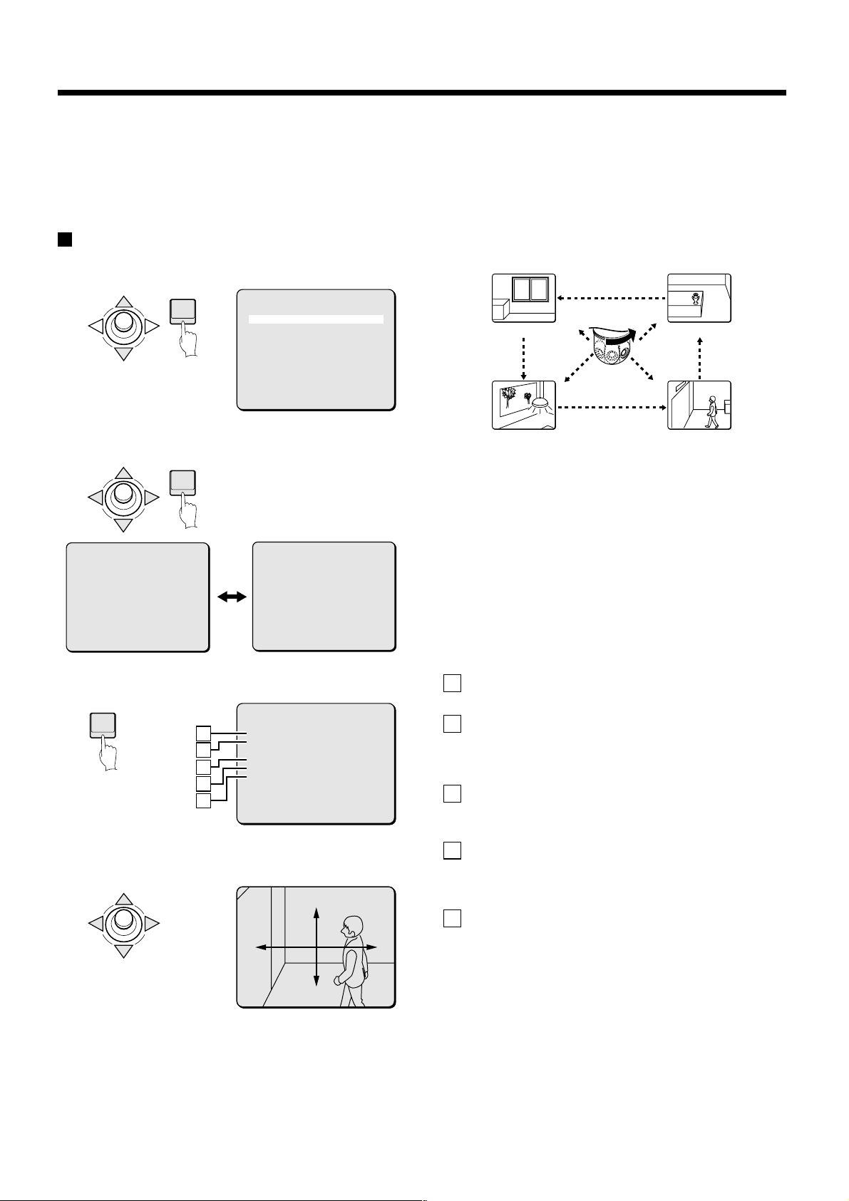
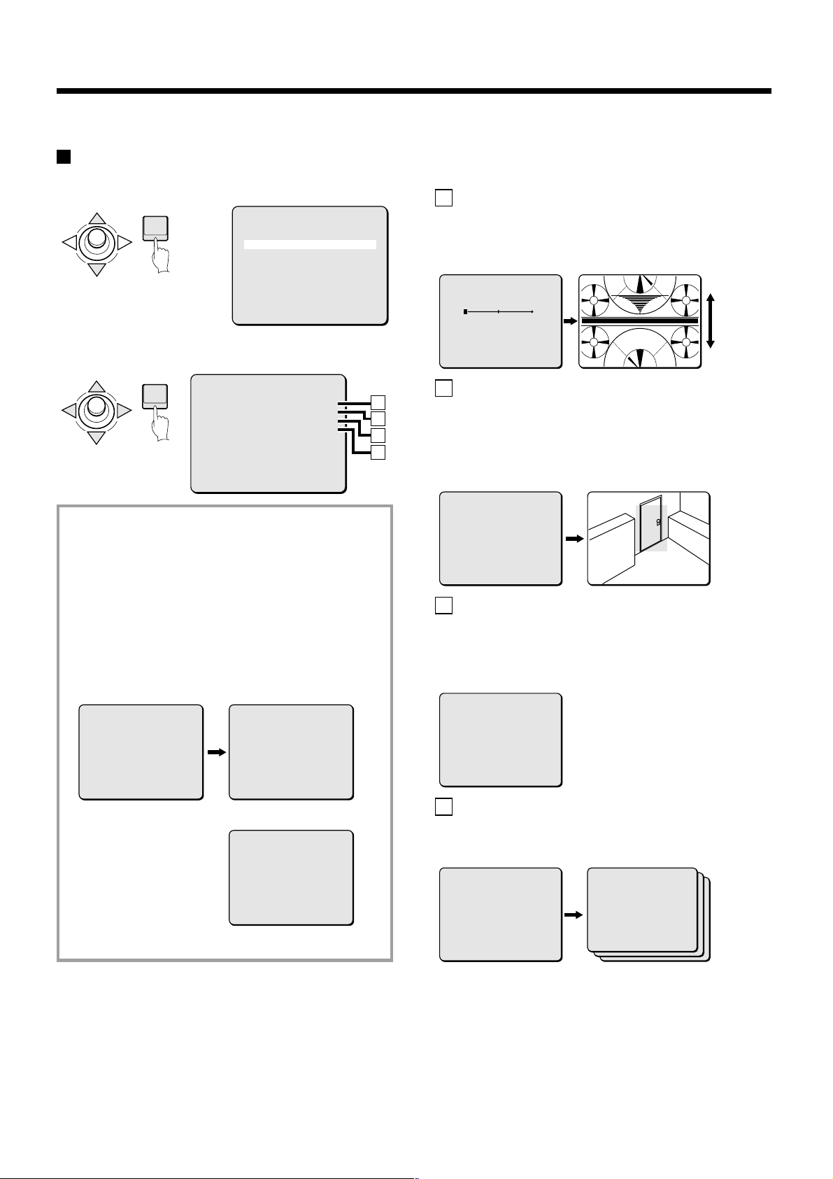
PRESET POSITION item flow
1
Select PRESET POSITION
(Example of camera movement after setting)
CAM-1 FLOOR-4 CAM-1 FLOOR-4
CAM-1 FLOOR-3 CAM-1 FLOOR-3
ENTER
2
Select a preset number (Example: 3)
ENTER
PRESET NO.SELECT
1:0 11:X 21:X 31:X
2:X 12:X 22:X 32:X
3:X 13:X 23:X 33:X
4:X 14:X 24:X 34:X
5:X 15:X 25:X 35:X
6:X 16:X 26:X 36:X
7:X 17:X 27:X 37:X
8:X 18:X 28:X 38:X
9:X 19:X 29:X 39:X
10:X 20:X 30:X 40:X
3
Set parameters for the preset number (3)
ENTER
A
B
C
D
E
4
Decide on a surveillance position for the preset number
MAIN MENU
LANGUAGE SET ‚
PRESET POSITION SET ‚
CAMERA SET ‚
AUTO MODE PAN ‚
AUTO FLIP OFF
ALARM OFF
FREEZE OFF
REFRESH OFF
STARTING POINT OFF
MENU END
PRESET NO.SELECT
41:X 51:X 61:X
42:X 52:X 62:X
43:X 53:X 63:X
44:X 54:X 64:X
45:X 55:X BACK
46:X 56:X
47:X 57:X
48:X 58:X
49:X 59:X
50:X 60:X
PRESET SETTING
PRESET NO. 3 ‚
DELETE SET ‚
TITLE OFF
CAMERA VIEW 1
PAUSE TIME 5S
MENU BACK
(3)
PRESET SETTING
PRESET SETTING
Surveillance position 4 Surveillance position 3
No.2
No.3
CAM-1 FLOOR-2 CAM-1 FLOOR-2
No.4
CAM-1 FLOOR-1 CAM-1 FLOOR-1
Surveillance position 1 Surveillance position 2
(Selecting preset numbers)
In this screen you can select which preset number you want to use
for a particular surveillance location. Factory settings are shown
below.
Number 1: “0” (This is reserved for the home position and
•
always shows 0. It cannot be changed.)
Numbers 2 – 64: “X” shows the initial setting. When a preset
•
number is utilized, the signal letter changes to “0”.
Two screens are used to present all the preset numbers. Use the
joystick lever to switch to the other screen.
To cancel a preset setting operation, move the cursor to BACK and
then press the ENTER button.
(Preset number item settings)
PRESET NO.:
A
The preset number (3) selected is shown.
DELETE:
B
Select this item to delete stored information for this preset number.
PRESET NO. 1 represents the home position and cannot be
deleted, so the DELETE command is not shown for number 1.
TITLE:
C
This item sets the camera ID and title for the preset number.
When a title is set, it will be superimposed on the screen for that position.
CAMERA VIEW:
D
This enables adding of camera setting patterns made in the VIEW
SETTING menu item. Only the number for the detailed settings file
(0 – 8) can be entered here. (See p27)
PAUSE TIME:
E
This item sets the duration of pauses at surveillance locations
(Preset positions) when using sequential automatic display
(Sequential pan).
SET
SET ‚
‚
– 10 –
English
Page 12
PRESET POSITION SETTINGS
PRESET SETTING
SET
R
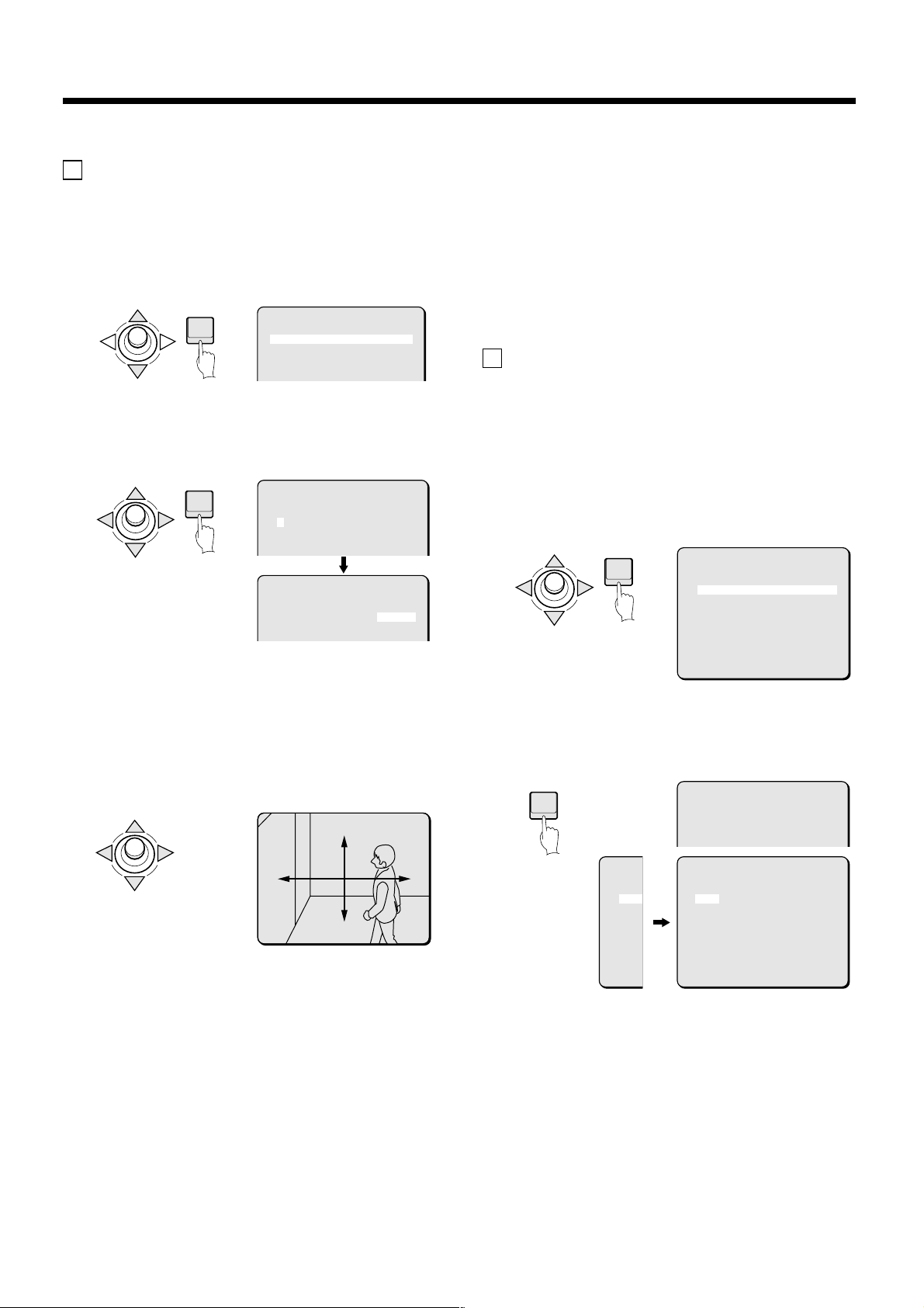
A Preset position settings (PRESET NO.)
Example: Establishing a surveillance location for
PRESET NO. 3.
1
In the MAIN MENU, select SET for PRESET POSITION and
press the ENTER button.
The PRESET NO. SELECT screen will appear.
ENTER
2
Use the joystick lever (j or l) to select number 3 and
press the ENTER button.
The PRESET SETTING screen will appear, and the number 3
will be blinking in the PRESET NO. field.
ENTER
MAIN MENU
LANGUAGE SET ‚
PRESET POSITION SET ‚
CAMERA SET ‚
AUTO MODE PAN ‚
AUTO FLIP OFF
ALARM OFF
PRESET NO.SELECT
1:0 11:X 21:X 31:X
2:X 12:X 22:X 32:X
3:X 13:X 23:X 33:X
4:X 14:X 24:X 34:X
5:X 15:X 25:X 35:X
6:X 16:X 26:X 36:X
PRESET SETTING
PRESET NO. 3 ‚
DELETE SET ‚
TITLE OFF
5
Press the ENTER button again.
The menu setting screen will reappear. Repeat steps 2 – 4 to
store other preset positions.
Set the corresponding TITLE, CAMERA VIEW and PAUSE
TIME for each of the new PRESET NO.
Note: When several cameras are used together, the CAMERA ID
menu item can be used to display information distinguishing
which camera is in use. Refer to “Camera ID setting” for
further information. (See p12)
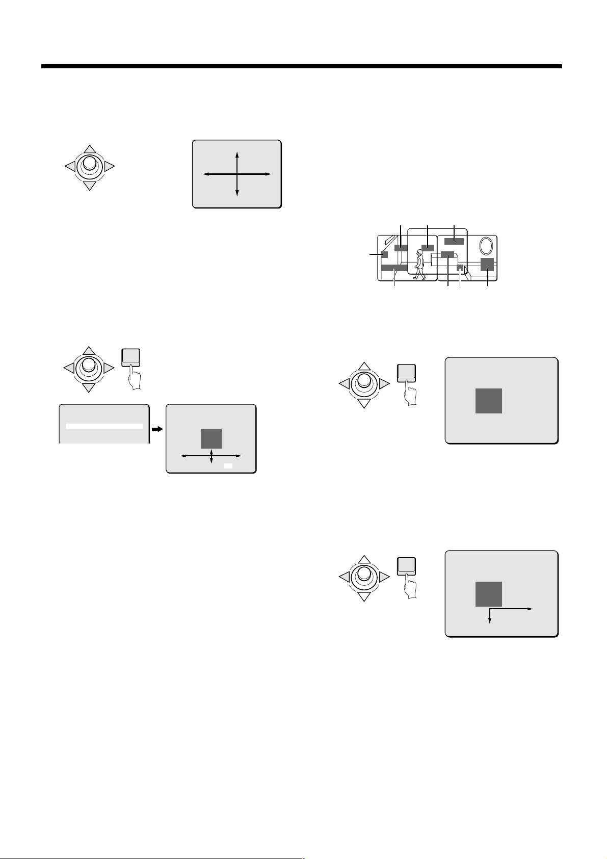
B Deleting preset positions (DELETE)
Example: Deleting preset position 3
1
In the PRESET NO. SELECT screen, select preset number 3
and press the ENTER button.
The PRESET SETTING screen will appear.
2
Use the joystick lever (j or l) to move the cursor to SET
for DELETE and press the ENTER button.
The confirmation message “OK?” will appear under SET.
ENTER
PRESET SETTING
PRESET NO. 3 ‚
DELETE SET ‚
OK?
TITLE OFF
CAMERA VIEW OFF
PAUSE TIME 5S
3
Press the ENTER button.
The menu setting screen will be replaced by an image of the
surveillance location.
4
Use the joystick lever (j l d c) to determine the
position to be stored for preset position 3.
Moving the joystick lever will move the camera so that the
desired surveillance location can be found.
PRESET SETTING
PRESET SETTING
SET
SET ‚
Note:
Storage of preset positions can be completed on either the
•
camera’s menu or from the system controller.
When auto flip is set to ON for a preset position, the preset
•
location may slip a little. In this case, reset the setting to correct
the problem.
MENU BACK
3
Press the ENTER button again.
Information stored for the surveillance location will be deleted.
The signal letter for the corresponding preset number will
change from “0” to “X” in the PRESET NO. SELECT screen.
ENTER
P
1:0
2:X
3:0
4:X
5:X
‚
6:X
7:X
8:X
9:X
10:X
PRESET SETTING
PRESET NO. 3 ‚
DELETE SET ‚
TITLE OFF
PRESET NO.SELECT
1:0 11:X 21:X 31:X
2:X 12:X 22:X 32:X
3:X 13:X 23:X 33:X
4:X 14:X 24:X 34:X
5:X 15:X 25:X 35:X
6:X 16:X 26:X 36:X
7:X 17:X 27:X 37:X
8:X 18:X 28:X 38:X
9:X 19:X 29:X 39:X
10:X 20:X 30:X 40:X
English
– 11 –
Page 13
PRESET POSITION SETTINGS
C The Camera ID and TITLE setting screen
Camera ID setting
Example: Setting the Camera ID to “CAM 1”
1
In the PRESET NO. SELECT screen, select preset number
1 and press the ENTER button.
The PRESET SETTING screen will appear.
2
Use the joystick lever (j or l) to move the cursor to
TITLE, and then use the joystick lever (d or c) to change
the setting to ON. Then press the ENTER button.
The TITLE SETTING screen will appear.
PRESET SETTING
PRESET NO. 1 ‚
DELETE SET ‚
TITLE ON ‚
CAMERA VIEW 1
PAUSE TIME 5S
MENU BACK
3
Use the joystick lever (j l d c) to move the cursor to
the first space of TITLE entry field, and then use the
joystick lever (d or c) to move the cursor to the first
space of ID field.
TITLE SETTING
ABCDEFGHIJKLM
NOPQRSTUVWXYZ
0123456789 : ID TITLE
???????? ????????
POSITION H ‚
PRESET NO. OFF
PRESET OFF
MENU BACK
4
Use the joystick lever (j l d c) to move the cursor to
the letter “C” in the letter selection palette, then press the
ENTER button.
5
Use the same steps to select “A”, “M” and “1” from the
palette.
The characters “CAM1” appear in the ID field.
ID TITLE
CAM1???? ????????
-
-
TITLE setting
Example: Setting the TITLE to “FLOOR-1”
1
Use the joystick lever (j or l) to move the cursor to the
first position “?” of the TITLE field.
ID TITLE
CAM1???? ????????
-
2
Enter a title using the same method given for camera ID
setting.
ID TITLE
CAM1???? FLOOR-1?
Camera ID and TITLE screen
TITLE SETTING
ABCDEFGHIJKLM
1
2
3
4
5
The letter selection palette:
1
By moving the cursor to letters or numbers in this palette,
you can select characters.
Selected characters will appear in the corresponding field
under ID or TITLE.
ID/TITLE:
2
ID: The ID for this camera is set by preset
•
The ID entry field shows 8 question marks (?). The
•
ID will not be displayed on the screen.
NOPQRSTUVWXYZ
0123456789 : ID TITLE
???????? ????????
POSITION H ‚
PRESET NO. ON
PRESET OFF
MENU BACK
position 1. It cannot be set by other preset
position numbers.
-
• The cursor first appears in the first space of the
TITLE field. To set the ID, use the joystick lever
(d or c) to move the cursor to the first space of
the ID field.
If TITLE is OFF for PRESET NO. 1, the ID will not
•
be displayed.
TITLE: A title can be set for each preset position.
•
The TITLE entry field shows 8 question marks (?).
•
When a letter is set, the next question mark will
disappear so the next letter can be set.
The TITLE will appear on the screen, as input in
•
the TITLE entry field.
POSITION:
3
Select the style in which the ID and/or title will appear,
either horizontally (H) or vertically (V).
PRESET NO.:
4
When ON is selected for this setting, the preset number
is displayed in front of the camera ID on the surveillance
screen.
PRESET:
5
When this item is turned to ON, the ID and TITLE fields
are cleared (question marks appear). Use this function
when you want to change the ID or TITLE.
– 12 –
English
Page 14
PRESET POSITION SETTINGS
On-screen title POSITION setting
1
Use the joystick lever (j or l) to move the cursor to
POSITION, and then use the joystick lever (d or c) to
select the display method (H or V). Then press the ENTER
button.
The following screen will appear.
ENTER
Note: Set preset positions can be checked by pressing the
numerical buttons and then the ENTER button on the
system controller while in normal viewing. The camera
will move to the preset position number that was
pressed.
Horizontally (H) position display
•
Change the POSITION setting to “H”.
TITLE SETTING
ABCDEFGHIJKLN
NOPQRSTUVWXYZ
0123456789 : ID TITLE
CAM1 FLOOR-1
POSITION H ‚
PRESET NO. ON
PRESET OFF
MENU BACK
Vertically (V) position display
•
1 CAM1 FLOOR-1
TITLE name
ID No.
Preset No.
Change the POSITION setting to “V”.
TITLE SETTING
ABCDEFGHIJKLN
NOPQRSTUVWXYZ
0123456789 : ID TITLE
CAM1 FLOOR-1
POSITION V ‚
PRESET NO. ON
PRESET OFF
MENU BACK
1
CAM1
FLOOR-1
ID No.
TITLE name
Preset No.
Note: To have the preset number displayed on normal viewing
screen, set PRESET NO. to “ON”. If this field is set to “OFF”,
the preset number will not be displayed on the screen.
☞ Moving the on-screen title display position
D CAMERA VIEW setting
Before making any setting change in this item, go to the VIEW
SETTING item of the CAMERA SETTINGS menu and establish up
to 9 patterns of camera settings. From among those 9 viewing
patterns, select the number of the most suitable pattern for each of
the preset surveillance locations.
☞ Use the joystick lever (j or l) to move the
cursor to CAMERA VIEW, then use the joystick
lever (d or c) to select the value to a pattern
number.
PRESET SETTING
PRESET NO. 3 ‚
DELETE SET ‚
TITLE OFF
CAMERA VIEW 1
PAUSE TIME 5S
Available settings: 0 – 8
E PAUSE TIME settings
Sets the duration time of image pausing when using sequential
automatic display (Sequential pan).
☞ Use the joystick lever (j or l) to move the
cursor to PAUSE TIME, then use the joystick
lever (d or c) to select the value to a pattern
number.
PRESET SETTING
PRESET NO. 3 ‚
DELETE SET ‚
TITLE OFF
CAMERA VIEW 1
PAUSE TIME 5S
Available settings: 3S, 5S, 10S, 15S, 20S, 30S, 45S, 60S, SKIP.
SKIP: Ignores the designated preset position and continues
sequential pan operation.
Canceling a settings screen
To return to the normal screen, use the joystick lever (l c) to
select END for MENU, then press the ENTER button.
2
Use the joystick lever (j l d c) to move the title
display to the preferred position on the screen.
1 CAM1 FLOOR-1
English
– 13 –
Page 15
CAMERA SETTINGS
CAMERA SETTING item flow
1
Select CAMERA
ENTER
2
Select CAMERA SETTING
MAIN MENU
LANGUAGE SET ‚
PRESET POSITION SET ‚
CAMERA SET ‚
AUTO MODE PAN ‚
AUTO FLIP OFF
ALARM OFF
FREEZE OFF
REFRESH OFF
STARTING POINT OFF
MENU END
Select CAMERA SETTING
A SYNC: (See p15)
Sets camera to internal synchronization (INT) or power source
synchronization (L-L).
Power source synchronization adjusts the vertical synchronization
phase.
L-L SETTING
(V SYNC PHASE)
0
PRESET OFF
MENU BACK
ENTER
CAMERA SETTING
SYNC INT
PRIVACY MASK SET ‚
LENS SET ‚
VIEW SETTING 1 ‚
PRESET OFF
MENU BACK
(About creating image setting files in VIEW SETTING)
You can set 9 different patterns with view files. Use the
joystick lever (d or c) to change the file number (1) for
VIEW SETTING and press the ENTER button. The selected
image setting file will appear. Neither the mask function nor
the motion detector function can be used with image setting
file “0”, so they will not appear as options in the screen for
pattern 0.
Note: If images are at a position other than the preset
position because of manual operations, VIEW
SETTING will automatically switch the image setting
to file “0”.
CAMERA SETTING
SYNC INT
PRIVACY MASK SET ‚
LENS SET ‚
VIEW SETTING 3 ‚
PRESET OFF
MENU BACK
VIEW SETTING 3
IRIS AUTO ‚
WHITE BALANCE ATW ‚
SHUTTER OFF
MOTION OFF
APERTURE ON ‚
GAMMA ON
PRESET OFF
MENU BACK
(Screen for image setting 1 – 8)
VIEW SETTING 0
IRIS AUTO ‚
WHITE BALANCE ATW ‚
SHUTTER OFF
MOTION -- APERTURE ON ‚
GAMMA ON
PRESET OFF
MENU BACK
(Screen for image setting 0)
A
B
C
D
This covers an area of the screen with a gray pattern for areas that
may infringe on privacy.
Gray patterns can be placed on up to 8 areas. However, any single
surveillance screen cannot have more than 4 of the masked areas
that have been set. Masked areas cannot be set beyond these
limits.
PRIVACY MASK SETTING
PASSWORD LOCK OFF ‚
PASSWORD CHANGE SET ‚
MASK SET SET ‚
MENU BACK
C LENS: (See p18)
B PRIVACY MASK: (See p15)
This lets you make settings such as automatic and manual focus
settings, zoom speed and zoom ratio. In addition, it can also be
used for automatic switching to color images during daytime, or to
black and white images at times of low luminance such as
nighttime.
LENS
FOCUS MANU ‚
ZOOM SET ‚
DAY/NIGHT AUTO ‚
VIEW ANGLE OFF
PRESET OFF
MENU BACK
D VIEW SETTING: (See p27)
Different detailed settings can be made for each camera (9
screens). After they are set, these are linked to “CAMERA
SETTING (0 – 8)” settings for preset positions.
VIEW SETTING 1
IRIS AUTO ‚
WHITE BALANCE ATW ‚
SHUTTER OFF
MOTION OFF
APERTURE ON ‚
GAMMA ON
PRESET OFF
MENU BACK
VIEW SETTING 0
IRIS AUTO ‚
WHITE BALANCE ATW ‚
SHUTTER OFF
MOTION -- APERTURE ON ‚
GAMMA ON
PRESET OFF
MENU BACK
Note:
Making any setting while electronic zoom is active will cancel
•
the electronic zoom condition.
If VIEW SETTING has been set to a value from 1 to 8 for the
•
various preset positions during automatic preset operation,
operation will change automatically to manual operation if you
operate the joystick lever (dcjl), and VIEW SETTING will
also be set to “0”.
As a result, be sure to set VIEW SETTING to “0” during manual
operation.
– 14 –
English
Page 16
CAMERA SETTINGS
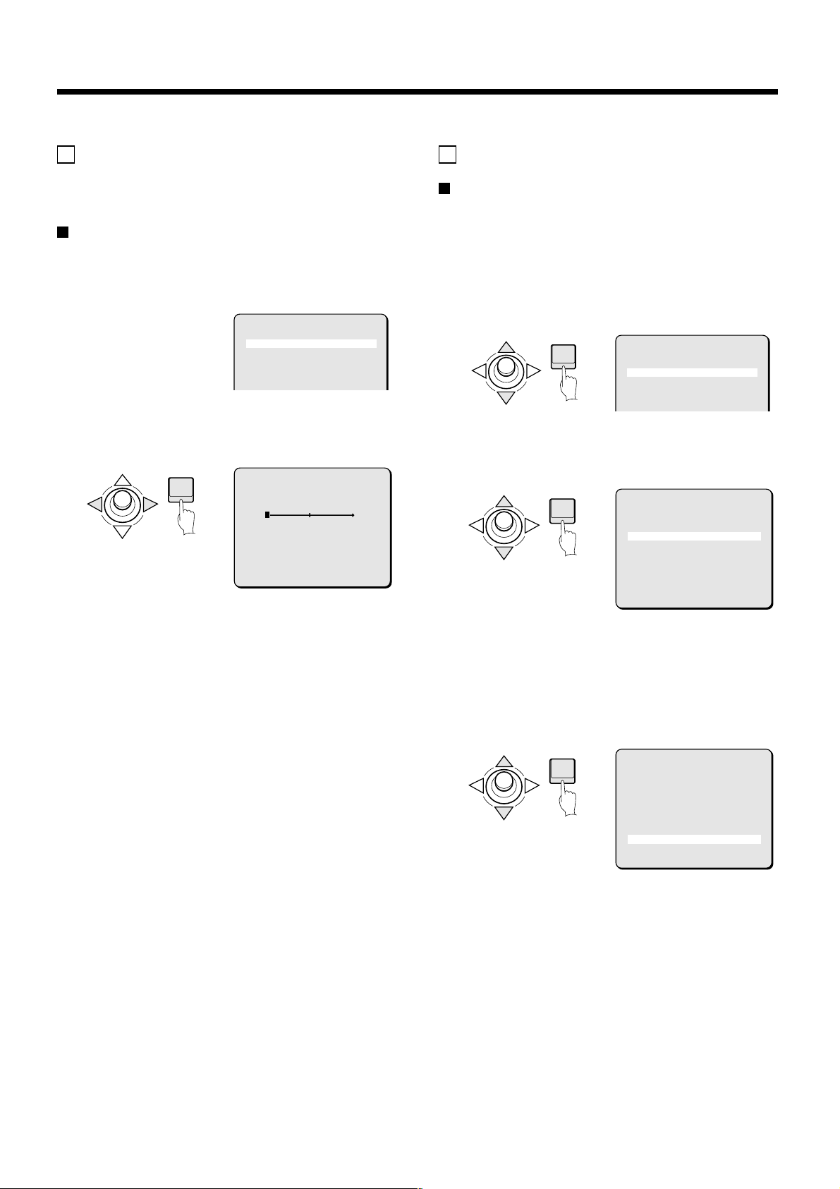
A SYNC setting
Initial setting is internal synchronization (INT), so it does not need
to be set again. Follow the steps below to change the setting to
power source synchronization (L-L).
Power source synchronization (L-L) setting
1
In the MAIN MENU, select SET for CAMERA and press the
ENTER button.
The CAMERA SETTING screen will appear.
CAMERA SETTING
SYNC INT
PRIVACY MASK SET ‚
LENS SET ‚
VIEW SETTING 1 ‚
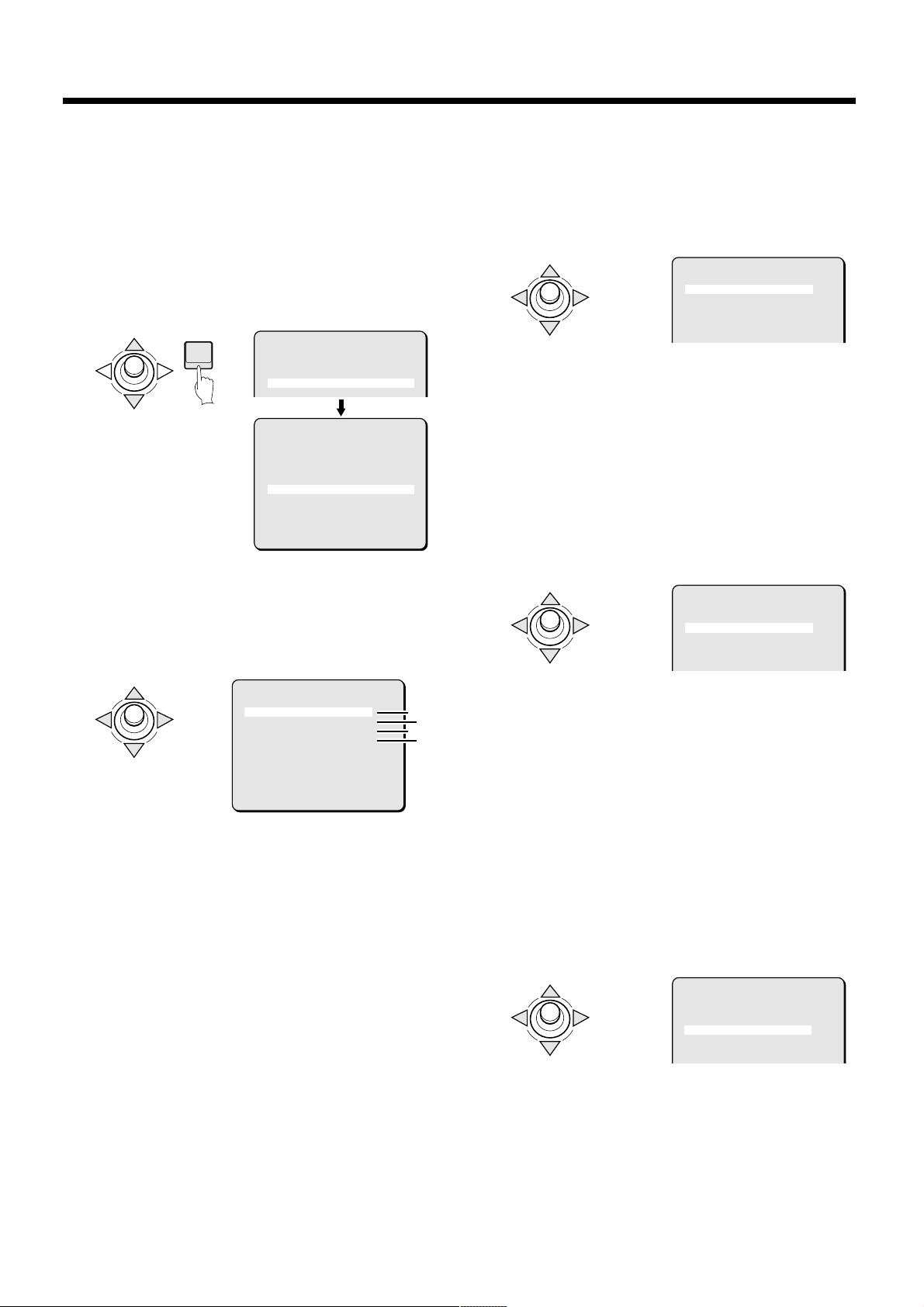
2
Use the joystick lever (j or l) to select L-L for SYNC,
then press the ENTER button.
The L-L SETTING screen will appear.
ENTER
L-L SETTING
(V SYNC PHASE)
0
B PRIVACY MASK setting
Mask setting
1
In the MAIN MENU, select SET for CAMERA and press the
ENTER button.
The CAMERA SETTING screen will appear.
2
Use the joystick lever (j or l) to select SET for PRIVACY
MASK, then press the ENTER button.
The PRIVACY MASK SETTING screen will appear.
ENTER
3
Use the joystick lever (j or l) to move the cursor to SET
for MASK SET and press the ENTER button.
The MASK NO. SELECT screen will appear.
ENTER
CAMERA SETTING
SYNC INT
PRIVACY MASK SET ‚
LENS SET ‚
VIEW SETTING 1 ‚
PRIVACY MASK SETTING
PASSWORD LOCK OFF ‚
PASSWORD CHANGE SET ‚
MASK SET SET ‚
PRESET OFF
MENU BACK
Available settings: 0 – 624
3
Use the joystick lever (d or c) to adjust the position of
the vertical synchronization indicator shown on the
screen.
The numerical value will change, allowing adjustment of
vertical synchronization.
4
Canceling a settings screen
Use the joystick lever (l) to select BACK for MENU, then
•
press the ENTER button. The CAMERA SETTING screen
will reappear.
To return to the normal screen, use the joystick lever (l
•
c) to select END for MENU, then press the ENTER button.
MENU BACK
Note: When PASSWORD LOCK is ON, moving the cursor to
MASK SET and press the ENTER button to bring up a
password access screen. The password must be entered in
this screen.
4
Use the joystick lever (j or l) to move the cursor to SET
for DIRECTION and press the ENTER button.
The DIRECTION screen will appear.
ENTER
Note: If no “*” mark appears next to the screen title “MASK NO.
SELECT”, privacy masks cannot be set. Changing the
joystick lever angle so that the “*” mark appears will allow
setting of masks.
MASK NO.SELECT *
MASK 1 OFF
MASK 2 OFF
MASK 3 OFF
MASK 4 OFF
MASK 5 OFF
MASK 6 OFF
MASK 7 OFF
MASK 8 OFF
DIRECTION SET ‚
PRESET OFF
MENU BACK
English
– 15 –
Page 17
CAMERA SETTINGS
5
Use the joystick lever (j l d c) to decide in which
direction the mask will be made.
(DIRECTION) *
SET ‚
6
Press the ENTER button.
The MASK NO. SELECT screen will reappear.
7
Use the joystick lever (j or l) to move the cursor to a
mask number (Ex: MASK 3), and then use the joystick
lever (d) to change the setting to SET. Then press the
ENTER button.
The MASK 3 SET (POSITION) screen will appear, and SETy
will be blinking. The gray mask will appear in the center of the
screen.
ENTER
(About the POSITION screen)
It is possible to set as many as 4 masks on the same POSITION
screen. Even if a fifth mask is placed, SETy will not appear.
Note:
By stacking single screens with 4 masks on them it is possible
•
to set as many as 8 masks. See the example below for an
illustration of the use of 8 gray masks.
The area under a mask can be seen when the camera is
•
changing preset positions. To compensate for this, make the
masks a little larger when necessary.
346
MASK1
2
8
Use the joystick lever (d or c) to move the gray mask,
5 7 8
then press the ENTER button.
The SIZE screen will appear, and the mask that was
positioned in the POSITION screen will be displayed.
ENTER
MASK 3 SET
(SIZE)
MASK NO SELECT
MASK 1 OFF
MASK 2 OFF
MASK 3 SET ‚
MASK 4 OFF
MASK 5 OFF
MASK 6 OFF
MASK 7 OFF
MASK 8 OFF
DIRECTION SET ‚
PRESET OFF
MENU BACK
MASK 3 SET
(POSITION)
SET ‚
Joystick lever operation
OFF: to c side (ON appears), to c side again (SET appears)
SET: Mask POSITION and SIZE can be set
•
ON: Masks can be displayed
•
OFF: Masks can be deleted
•
SET ‚
9
Use the joystick lever (d or c) to adjust the size of the
gray mask, then press the ENTER button.
PRESET and MENU will appear at the bottom of the screen.
Move the cursor to BACK for MENU and press the ENTER
button. The screen will return to MASK NO. SELECT and the
MASK 3 setting will be ON.
To return to the normal screen, use the joystick lever (l c) to
select END for MENU, then press the ENTER button.
ENTER
MASK 3 SET
(SIZE)
PRESET OFF
MENU BACK
– 16 –
English
Page 18

CAMERA SETTINGS
PASSWORD setting
You can lock the privacy masks in place after they have been set.
The password requirement is initially set to OFF, but to begin using
it, you must enter the factory set password “1234”.
1
Use the joystick lever (j or l) to move the cursor to OFF
for PASSWORD LOCK in the PRIVACY MASK SETTING
screen. Then press the ENTER button.
The PASSWORD screen will appear.
ENTER
PRIVACY MASK SETTING
PASSWORD LOCK OFF ‚
PASSWORD CHANGE SET ‚
MASK SET SET ‚
PASSWORD
MENU BACK
**** SET ‚
MENU BACK
-
☞ Enter the factory set password “1234”.
2
Use the joystick lever (j or l) to select “1”, then use the
joystick lever (c).
To move the cursor to the next “*” digit.
☞ Enter the factory set password “1234”.
2
Use the joystick lever (j or l) to select “1”, then use the
joystick lever (c).
To move the cursor to the next “*” digit.
3
Use the same steps to enter “2,” “3,” and “4,” then press
the ENTER button.
“OK” will appear and BACK for MENU will be blinking. Press
the ENTER button again. The PRIVACY MASK SETTING
screen will reappear and “ON” will be blinking for PASSWORD
LOCK.
PASSWORD
1234 SET ‚
OK
-
PRIVACY MASK SETTING
PASSWORD LOCK OFF ‚
PASSWORD CHANGE SET ‚
MASK SET SET ‚
PASSWORD changes
You can change the password with PASSWORD LOCK in either
the ON or OFF setting.
1
Use the joystick lever (j or l) to move the cursor to SET
for PASSWORD CHANGE and press the ENTER button.
The PASSWORD (NOW PASSWORD) screen will appear.
ENTER
PRIVACY MASK SETTING
PASSWORD LOCK ON ‚
PASSWORD CHANGE SET ‚
MASK SET SET ‚
1¤¤¤
3
Use the same steps to enter “2,” “3,” and “4,” then press
the ENTER button.
“OK” will appear and BACK for MENU will be blinking. Press
the ENTER button again. The PRIVACY MASK SETTING
screen will reappear and “ON” will be blinking for PASSWORD
LOCK.
PASSWORD
1234 SET ‚
OK
MENU BACK
-
Note: If a different password is required, “NG” will appear. Please
carefully maintain the password so that it will not be
forgotten.
PASSWORD cancellation
For use when PASSWORD LOCK is ON
1
Press the ENTER button.
The PASSWORD screen will appear.
ENTER
PRIVACY MASK SETTING
PASSWORD LOCK ON ‚
PASSWORD CHANGE SET ‚
MASK SET SET ‚
MENU BACK
PASSWORD
PASSWORD
(NOW PASSWORD)
**** SET ‚
2
Use the joystick lever (d or c, j) to enter the current
-
password (Ex: 1234), then press the ENTER button.
The PASSWORD (NEW PASSWORD) screen will appear.
PASSWORD
(NOW PASSWORD)
1234 SET ‚
3
Use the joystick lever (d or c, j) to enter a new
-
PASSWORD
(NEW PASSWORD)
**** SET ‚
-
password (Ex: 4321), then press the ENTER button.
“OK” will appear and BACK for MENU will be blinking. Press
the ENTER button again.
The PRIVACY MASK SETTING screen will reappear.
English
**** SET ‚
-
– 17 –
Page 19

CAMERA SETTINGS
C LENS setting item flow
1
2
Select CAMERA
ENTER
Select LENS
ENTER
MAIN MENU
LANGUAGE SET ‚
PRESET POSITION SET ‚
CAMERA SET ‚
AUTO MODE SEQ ‚
AUTO FLIP OFF
ALARM OFF
FREEZE OFF
REFRESH OFF
STARTING POINT OFF
MENU END
CAMERA SETTING
SYNC INT
PRIVACY MASK SET ‚
LENS SET ‚
VIEW SETTING 1 ‚
PRESET OFF
MENU BACK
LENS
FOCUS MANU ‚
ZOOM SET ‚
DAY/NIGHT AUTO ‚
VIEW ANGLE OFF
PRESET OFF
MENU BACK
A
FOCUS: (See page 19)
FOCUS SETTING
LIMIT NEAR 1M
SPEED 2
These settings let you select automatic
focus (AUTO) or manual focus. Change
the focus settings in accordance with
the monitoring conditions.
PRESET OFF
MENU BACK
B
ZOOM: (See page 21)
ZOOM SETTING
SPEED 3
EL ZOOM OFF
V-RESO.UP OFF
PRESET OFF
MENU BACK
C
DAY/NIGHT: (See page 22)
D/N SETTING - AUTO
AGC MAX GAIN +3·
DNR OFF
BURST OFF
FOCUS 1
LEVEL MID
PRESET OFF
MENU BACK
(AUTO mode)
D/N SETTING - COLOR
AGC MAX GAIN OFF ‚
DNR OFF
PRESET OFF
MENU BACK
(COLOR mode)
D/N SETTING - B/W
AGC MAX GAIN OFF ‚
DNR OFF
BURST OFF
FOCUS 1
These settings let you adjust the speed
and zoom ratio when using electronic
zoom.
These settings can be used for
automatic switching to color images
during daytime, or to black and white
images at times of low luminance such
as nighttime. Three modes (AUTO,
COLOR and B/W) can be selected.
Change the settings in accordance with
the monitoring conditions.
– 18 –
PRESET OFF
MENU BACK
(B/W mode)
VIEW ANGLE: (See page 26)
D
LENS
FOCUS MANU ‚
ZOOM SET ‚
DAY/NIGHT AUTO ‚
VIEW ANGLE OFF
PRESET OFF
MENU BACK
These settings are for setting the image
angle.
If “OVER” is set, the image angle is set
to approximately 1.05.
English
Page 20

CAMERA SETTINGS
FOCUS setting
A
Setting the manual focus (MANU)
•
Sets a limit for near distance focusing and sets focus speed for
manual focus.
1
In the MAIN MENU, select SET for CAMERA and press the
ENTER button.
The CAMERA SETTING screen will appear.
2
Use the joystick lever (j or l) to select SET for LENS,
then press the ENTER button.
The LENS screen will appear.
ENTER
3
Use the joystick lever (d or c) to select MANU, then
press the ENTER button.
The FOCUS SETTING screen will appear.
CAMERA SETTING
SYNC INT
PRIVACY MASK SET ‚
LENS SET ‚
VIEW SETTING 1 ‚
LENS
PRESET OFF
MENU END
FOCUS MANU ‚
ZOOM SET ‚
DAY/NIGHT AUTO ‚
VIEW ANGLE OFF
PRESET OFF
MENU BACK
FOCUS SETTING
LIMIT NEAR 1M
SPEED 2
☞ LIMIT NEAR focus distance setting
4
Use the joystick lever (j or l) to move the cursor to
LIMIT NEAR, then use the joystick lever (d or c) to
change the distance value. (Ex: 3M)
☞ SPEED of focus setting
5
Use the joystick lever (j or l) to move the cursor to
SPEED, then use the joystick lever (d or c) to select the
focus adjustment speed value. (Ex: 3)
FOCUS SETTING
LIMIT NEAR 3M
SPEED 3
PRESET OFF
MENU BACK
Available settings: 1, 2, 3, 4 (Quickest speed)
6
Canceling a settings screen
Use the joystick lever (l) to select BACK for MENU, then
•
press the ENTER button. The LENS screen will reappear.
To return to the normal screen, use the joystick lever (l
•
c) to select END for MENU, then press the ENTER button.
Setting the autofocus (AUTO)
•
Sets a limit for near distance focusing and sets focusing sensitivity
and focus iris.
Note: As a normal practice, use manual focus when keeping the
camera focused on the same target object for a long period
of time (over 24 hours). This can be used with the one-push
autofocus function when needed (operated from the system
controller). Long periods of surveillance with the autofocus in
operation will shorten the work life of the lens.
1
Use the joystick lever (j or l) to select SET for LENS,
then press the ENTER button.
The LENS screen will appear.
ENTER
CAMERA SETTING
SYNC INT
PRIVACY MASK SET ‚
LENS SET ‚
VIEW SETTING 1 ‚
FOCUS SETTING
LIMIT NEAR 3M
SPEED 2
Available settings: 1M (meter), 3M, 5M, 10C (centimeters),
Note: Focusing becomes difficult when near distance limit is set to
less than “1M”.
30C, 50C
English
– 19 –
LENS
FOCUS AUTO ‚
ZOOM SET ‚
DAY/NIGHT AUTO ‚
VIEW ANGLE OFF
PRESET OFF
MENU BACK
Page 21

CAMERA SETTINGS
2
Use the joystick lever (d or c) to select AUTO, then
press the ENTER button.
The FOCUS SETTING screen will appear.
ENTER
LENS
FOCUS AUTO ‚
ZOOM SET ‚
FOCUS SETTING
PRESET OFF
MENU BACK
LIMIT NEAR 1M
SENSITIVITY HIGH
AREA SET ‚
PRESET OFF
MENU BACK
☞ LIMIT NEAR focus distance setting
3
Use the joystick lever (j or l) to move the cursor to
LIMIT NEAR, then use the joystick lever (d or c) to
change the distance value. (Ex: 3M)
FOCUS SETTING
LIMIT NEAR 3M
SENSITIVITY HIGH
AREA SET ‚
5
Use the joystick lever (j or l) to move the cursor to SET
for AREA, and press the ENTER button.
The AREA SETTING screen for AREA 2 (initial setting) will
appear to allow setting of focus target area.
ENTER
6
Use the joystick lever (d or c) to select the focus target
area. (Ex: 3)
The focus target area will become narrow.
FOCUS SETTING
LIMIT NEAR 3M
SENSITIVITY LOW
AREA SET ‚
AREA SETTING
PRESET OFF
MENU BACK
AREA 2
PRESET OFF
MENU BACK
AREA SETTING
AREA 3
Available settings: 1M (meter), 3M, 5M, 10C (centimeters),
Note: Focusing becomes difficult when near distance limit is set to
less than “1M”.
30C, 50C
☞ Setting focus SENSITIVITY
4
Use the joystick lever (j or l) to move the cursor to
SENSITIVITY, then use the joystick lever (d or c) to
change the setting. (Ex: LOW)
FOCUS SETTING
LIMIT NEAR 3M
SENSITIVITY LOW
AREA SET ‚
Available settings:
HIGH: High sensitivity focusing
•
LOW: Low sensitivity focusing
•
Note: When focus SENSITIVITY is set to HIGH, it may react to
even slight movements of the target object. In this case,
change the setting to LOW.
PRESET OFF
MENU BACK
Available settings: 1/full screen, 2/center of screen,
4
Canceling a settings screen
Use the joystick lever (l) to select BACK for MENU, then
•
press the ENTER button. The FOCUS SETTING screen
will reappear.
To return to the normal screen, use the joystick lever (l
•
c) to select END for MENU, then press the ENTER button.
3/smaller center
– 20 –
English
Page 22

CAMERA SETTINGS
ZOOM setting
B
Sets zooming speed and magnification power of the electronic
zoom. This item also has a setting for improvement of vertical
resolution of still pictures.
1
In the MAIN MENU, select SET for CAMERA and press the
ENTER button.
The CAMERA SETTING screen will appear.
2
Use the joystick lever (j or l) to select SET for LENS,
then press the ENTER button.
The LENS screen will appear.
ENTER
3
Use the joystick lever (j or l) to select SET for ZOOM,
then press the ENTER button.
The ZOOM SETTING screen will appear.
ENTER
CAMERA SETTING
SYNC INT
PRIVACY MASK SET ‚
LENS SET ‚
VIEW SETTING 1 ‚
LENS
FOCUS MANU ‚
ZOOM SET ‚
DAY/NIGHT AUTO ‚
☞ V-RESO.UP (Vertical resolution) setting
6
Use the joystick lever (j or l) to move the cursor to
V-RESO.UP, then use the joystick lever (d or c) to select
the vertical resolution. (Ex: ON)
ZOOM SETTING
SPEED 4
EL ZOOM x4
V-RESO.UP ON
Note:
When V-RESO.UP is set to “ON”, vertical resolution sensitivity
•
for still pictures in the electronic zoom field will be improved but
afterimages of moving objects will be more conspicuous.
7
Canceling a settings screen
Use the joystick lever (l) to select BACK for MENU, then
•
press the ENTER button. The LENS screen will reappear.
To return to the normal screen, use the joystick lever (l
•
c) to select END for MENU, then press the ENTER button.
Note:
V-RESO. UP will be automatically set to OFF when any of the
following settings is made.
IRIS: AUTO item SENSE UP (ON)
•
SHUTTER: LONG
•
AGC: DNR (ON)
•
☞ Zoom speed setting
4
Use the joystick lever (d or c) to select the zooming
speed. (Ex: 4)
ZOOM SETTING
SPEED 4
EL ZOOM OFF
V-RESO.UP OFF
Available settings: 1, 2, 3, 4 (Quickest speed)
☞ EL ZOOM (Electronic zoom) magnification
setting
5
Use the joystick lever (j or l) to move the cursor to EL
ZOOM, then use the joystick lever (d or c) to select the
electronic zoom magnification power. (Ex: x4)
ZOOM SETTING
SPEED 4
EL ZOOM x4
V-RESO.UP OFF
Available settings: OFF, x2, x4, x8, x16 (16 power)
English
– 21 –
Page 23

CAMERA SETTINGS
DAY/NIGHT setting
C
This lets you set the filming mode to color mode during times of
normal brightness, or to black & white mode which removes the
infrared filter to increase sensitivity when there is less light. The
three available DAY/NIGHT settings are AUTO, COLOR and B/W.
LENS
FOCUS MANU ‚
ZOOM SET ‚
DAY/NIGHT AUTO ‚
VIEW ANGLE OFF
PRESET OFF
MENU BACK
AUTO: Automatic mode; The mode switches automatically
••••
between color mode and black & white mode depending on the
luminance of the objects being monitored.
COLOR: Color mode; Images are filmed in color regardless of
••••
the luminance of the objects being monitored.
B/W: Black & white mode; Images are filmed in black & white
••••
regardless of the luminance of the objects being monitored.
2
Use the joystick lever (j or l) to select SET for LENS,
then press the ENTER button.
The LENS screen will appear.
ENTER
3
Use the joystick lever (j or l) to move the cursor to
DAY/NIGHT, use the joystick lever (d or c) to select the
mode (example: AUTO), and then press the ENTER button.
The D/N SETTING - AUTO screen will appear, and the “+9dB”
setting for “AGC MAX GAIN” will be blinking.
CAMERA SETTING
SYNC INT
PRIVACY MASK SET ‚
LENS SET ‚
VIEW SETTING 1 ‚
LENS
PRESET OFF
MENU END
FOCUS MANU ‚
ZOOM SET ‚
DAY/NIGHT AUTO ‚
VIEW ANGLE OFF
PRESET OFF
MENU BACK
(Fig. 1)
Note:
A sound may be heard when the colour image or black and
••••
white image is switched. Also,the image will be distorted as
shown in Fig. 1. This is normal and does not indicate a problem.
When using infrared lighting,if there is a strong reflection on the
••••
subject, the optical filter may switch from black and white to
colour mode. Use only enough infrared lighting so that the
mode is not switched.
AUTO mode setting
••••
Note:
If the backlight conpensation has been set to “MULTI”, the
••••
backlight conpensation will be canceled when the mode is
switched to B/W.
If “SENSE UP” has been set to “ON”, SENSE UP mode will be
••••
activated after the mode switches to B/W mode.
1
In the MAIN MENU, select SET for CAMERA and press the
ENTER button.
The CAMERA SETTING screen will appear.
ENTER
D/N SETTING - AUTO
AGC MAX GAIN +9·
DNR OFF
BURST OFF
FOCUS 1
LEVEL MID
PRESET OFF
MENU BACK
1 Sets the maximum AGC gain.
2 Sets the digital noise reduction.
3 Sets burst suppression. If other peripheral devices (such
as a multiplexer) are connected to the system, bursts
(distortion of image color) can occur when switching
between color and black & white. If this happens, change
the BURST setting to “ON”.
4 Sets the focus when switching to black & white mode.
5 Sets the switching level for color mode and black & white
mode. The three available settings are LOW, MID or HIGH.
In addition, the switching level can be set manually (ADJ).
☞ AGC MAX GAIN setting
4
Use the joystick lever (j or l) to move the cursor to
AGC MAX GAIN, and then use the joystick lever (d or c)
to select the gain.
D/N SETTING - AUTO
AGC MAX GAIN +9·
DNR OFF
BURST OFF
FOCUS 1
LEVEL MID
1
3
5
2
4
– 22 –
PRESET OFF
MENU BACK
Available settings: Select the maximum AGC gain from
+9dB, +12dB or +15dB.
English
Page 24

CAMERA SETTINGS
☞ DNR setting
5
Use the joystick lever (j or l) to move the cursor to
DNR, and then use the joystick lever (d or c) to select
the digital noise reduction setting (example: ON).
D/N SETTING - AUTO
AGC MAX GAIN +9·
DNR ON
BURST OFF
FOCUS 1
LEVEL MID
Available settings:
ON: DNR (digital noise reduction) is applied. This reduces
••••
interference at low luminance levels.
OFF: DNR is not applied.
••••
Note: Digital noise reduction operates when the gain control
increases. In addition, blurring and ghosting of images
can occur when moving images are being monitored,
and so the resolution is also reduced slightly.
☞ BURST setting
6
Use the joystick lever (j or l) to move the cursor to
BURST, and then use the joystick lever (d or c) to select
the burst setting (example: ON).
D/N SETTING - AUTO
AGC MAX GAIN +9·
DNR ON
BURST ON
FOCUS 1
LEVEL MID
Available settings:
ON: The color burst signal is turned on.
••••
OFF: This should normally be set to “OFF”.
••••
☞ FOCUS setting
7
Use the joystick lever (j or l) to move the cursor to
FOCUS, and then use the joystick lever (d or c) to select
the focus setting (example: 1).
☞ LEVEL setting
8
Use the joystick lever (j or l) to move the cursor to
LEVEL, use the joystick lever (d or c) to select the level
setting (example: ADJ) and then press the ENTER button.
The LEVEL SETTING screen will appear.
ENTER
Available settings:
LOW: The mode switches when the luminance of the
••••
••••
••••
••••
9
Use the joystick lever (j or l) to move the cursor to
COLOR†B/W, and then use the joystick lever (d or c) to
select the value.
objects being monitored is comparatively dark.
MID: The mode switches when the luminance of the
objects being monitored is between the LOW and
HIGH levels.
HIGH: The mode switches when the luminance of the
objects being monitored is comparatively bright.
ADJ: The switching level for color mode to black & white
mode and for black & white mode to color mode
respectively can be set manually.
D/N SETTING - AUTO
AGC MAX GAIN +9·
DNR ON
BURST ON
FOCUS 1
LEVEL ADJ ‚
LEVEL SETTING
(COLOR†B/W)
4
(B/W†COLOR)
4
PRESET OFF
MENU BACK
LEVEL SETTING
(COLOR†B/W)
4
(B/W†COLOR)
4
D/N SETTING - AUTO
AGC MAX GAIN +9·
DNR ON
BURST ON
FOCUS 1
LEVEL MID
Available settings:
1: Near-infrared wavelength correction is set.
••••
(around 900 nm)
2: Visible light spectrum is set.
••••
Note: This should normally be set to “1”. If images are out of focus
in black & white mode, select a mode that gives better focus.
English –
23 –
PRESET OFF
MENU BACK
Available settings: 1 – 7
Note:
The larger the value, the darker the switching level.
••••
Changing the setting for one of the switching level settings
••••
(from color mode to black & white mode or from black &
white mode to color mode) causes the other setting to
change also.
Set the switching level from black & white mode to color
••••
mode in the same way.
Page 25

CAMERA SETTINGS
10
Canceling a settings screen
Use the joystick lever (l) to select BACK for MENU,
••••
then press the ENTER button. The LENS screen will
reappear.
To return to the normal screen, use the joystick lever (l
••••
c) to select END for MENU, then press the ENTER
button.
COLOR mode setting
••••
1
In the MAIN MENU, select SET for CAMERA and press the
ENTER button.
The CAMERA SETTING screen will appear.
2
Use the joystick lever (j or l) to select SET for LENS,
then press the ENTER button.
The LENS screen will appear.
ENTER
3
Use the joystick lever (j or l) to move the cursor to
DAY/NIGHT, use the joystick lever (d or c) to select the
level setting (example: COLOR) and then press the
ENTER button.
The D/N SETTING - COLOR screen will appear, and the
“±0dB” setting for “AGC MAX GAIN” will be blinking.
CAMERA SETTING
SYNC INT
PRIVACY MASK SET ‚
LENS SET ‚
VIEW SETTING 1 ‚
LENS
PRESET OFF
MENU END
FOCUS MANU ‚
ZOOM SET ‚
DAY/NIGHT AUTO ‚
VIEW ANGLE OFF
PRESET OFF
MENU BACK
D/N SETTING - COLOR
AGC MAX GAIN ±0·
DNR OFF
PRESET OFF
MENU BACK
1
2
☞ AGC MAX GAIN setting
4
Use the joystick lever (j or l) to move the cursor to
AGC MAX GAIN, and then use the joystick lever (d or c)
to select the gain.
D/N SETTING - COLOR
AGC MAX GAIN ±0·
DNR OFF
Available settings: Select the maximum AGC gain from
Note:
If “OFF” is selected, no maximum gain will be set.
••••
If “OFF” is selected, the SENSE UP function will be forcibly set
••••
to “OFF”. However, the setting display will not change.
OFF, –6dB, ±0dB, +6dB or +9dB.
☞ DNR setting
5
Use the joystick lever (j or l) to move the cursor to
DNR, and then use the joystick lever (d or c) to select
the digital noise reduction setting (example: ON).
D/N SETTING - COLOR
AGC MAX GAIN ±0·
DNR ON
Available settings:
ON: DNR (digital noise reduction) is applied. This reduces
••••
interference at low luminance levels.
OFF: DNR is not applied.
••••
Note:
Digital noise reduction operates when the gain control
••••
increases. In addition, blurring and ghosting of images can
occur when moving images are being monitored, and so the
resolution is also reduced slightly.
If AGC MAX GAIN is set to “OFF”, DNR will be forcibly set to
••••
“OFF”.
6
Canceling a settings screen
Use the joystick lever (l) to select BACK for MENU, then
••••
press the ENTER button. The LENS screen will reappear.
To return to the normal screen, use the joystick lever (l
••••
c) to select END for MENU, then press the ENTER button.
1 Sets the maximum AGC gain.
2 Sets the digital noise reduction.
– 24 –
English
Page 26
CAMERA SETTINGS
B/W mode setting
••••
☞ AGC MAX GAIN setting
1
In the MAIN MENU, select SET for CAMERA and press the
ENTER button.
The CAMERA SETTING screen will appear.
2
Use the joystick lever (j or l) to select SET for LENS,
then press the ENTER button.
The LENS screen will appear.
ENTER
3
Use the joystick lever (j or l) to move the cursor to
DAY/NIGHT, use the joystick lever (d or c) to select the
level setting (example: B/W) and then press the ENTER
button.
The D/N SETTING – B/W screen will appear, and the “+6dB”
setting for “AGC MAX GAIN” will be blinking.
CAMERA SETTING
SYNC INT
PRIVACY MASK SET ‚
LENS SET ‚
VIEW SETTING 1 ‚
LENS
PRESET OFF
MENU END
FOCUS MANU ‚
ZOOM SET ‚
DAY/NIGHT AUTO ‚
VIEW ANGLE OFF
PRESET OFF
MENU BACK
D/N SETTING - B/W
AGC MAX GAIN +6·
DNR OFF
BURST OFF
FOCUS 1
PRESET OFF
MENU BACK
1 Sets the maximum AGC gain.
2 Sets the digital noise reduction.
3 Sets burst suppression. If other peripheral devices (such
as a multiplexer) are connected to the system, bursts
(distortion of image color) can occur when switching
between color and black & white. If this happens, change
the BURST setting to “ON”.
4 Sets the focus when switching to black & white mode.
1
3
2
4
4
Use the joystick lever (j or l) to move the cursor to
AGC MAX GAIN, and then use the joystick lever (d or c)
to select the gain.
D/N SETTING - B/W
AGC MAX GAIN +6·
DNR OFF
BURST OFF
FOCUS 1
Available settings: Select the maximum AGC gain from
Note:
If “OFF” is selected, no maximum gain will be set.
••••
If “OFF” is selected, the SENSE UP function will be forcibly set
••••
to “OFF”. However, the setting display will not change.
OFF, –6dB, ±0dB, +6dB, +9dB, +12dB or
+15dB.
☞ DNR setting
5
Use the joystick lever (j or l) to move the cursor to
DNR, and then use the joystick lever (d or c) to select
the digital noise reduction setting (example: ON).
D/N SETTING - B/W
AGC MAX GAIN +6·
DNR ON
BURST OFF
FOCUS 1
Available settings:
ON: DNR (digital noise reduction) is applied. This reduces
••••
interference at low luminance levels.
OFF: DNR is not applied.
••••
Note:
Digital noise reduction operates when the gain control
••••
increases. In addition, blurring and ghosting of images can
occur when moving images are being monitored, and so the
resolution is also reduced slightly.
If AGC MAX GAIN is set to “OFF”, DNR will be forcibly set to
••••
“OFF”.
☞ BURST setting
6
Use the joystick lever (j or l) to move the cursor to
BURST, and then use the joystick lever (d or c) to select
the burst setting (example: ON).
English –
25 –
D/N SETTING - B/W
AGC MAX GAIN +6·
DNR ON
BURST ON
FOCUS 1
Available settings:
ON: The color burst signal is turned on.
••••
OFF: This should normally be set to “OFF”.
••••
Page 27

CAMERA SETTINGS
☞ FOCUS setting
7
Use the joystick lever (j or l) to move the cursor to
FOCUS, and then use the joystick lever (d or c) to select
the focus setting (example: 1).
D/N SETTING - B/W
AGC MAX GAIN +6·
DNR ON
BURST ON
FOCUS 1
Available settings:
1: Near-infrared wavelength correction is set.
••••
(around 900 nm)
2: Visible light spectrum is set.
••••
Note: This should normally be set to “1”. If images are out of focus
when black & white mode is used at nighttime, select “2”.
8
Canceling a settings screen
Use the joystick lever (l) to select BACK for MENU, then
••••
press the ENTER button. The LENS screen will reappear.
To return to the normal screen, use the joystick lever (l
••••
c) to select END for MENU, then press the ENTER button.
Day/Night mode operation from the system
••••
controller
The Day/Night setting (AUTO, COLOR and B/W) can be
switched using “CAMERA” operating range of the system
controller. Press the following buttons in the order given to
change the mode setting.
COLOR mode:
••••
“AUX“ + “AUX” + “1” + “Enter” + “+” button
B/W mode:
••••
“AUX“ + “AUX” + “2” + “Enter” + “+” button
AUTO mode:
••••
“AUX“ + “AUX” + “3” + “Enter” + “+” button
VIEW ANGLE setting
D
The VIEW ANGLE setting should normally be left at “OFF”.
1
In the MAIN MENU, select SET for CAMERA and press the
ENTER button.
The CAMERA SETTING screen will appear.
2
Use the joystick lever (j or l) to select SET for LENS,
then press the ENTER button.
The LENS screen will appear.
ENTER
3
Use the joystick lever (j or l) to move the cursor to
VIEW ANGLE, and then use the joystick lever (d or c) to
select the setting (example: OFF).
Available settings:
OVER: The image angle for images being monitored is set
••••
••••
Note: This setting should normally be “OFF”. However, vignetting
may occur in the corners of the images because of the zoom
position. This is not normally a problem, but if you are
concerned about it, change the setting to “OVER”. The
vignetting will then be less apparent.
to 1.05.
OFF: This setting should normally be “OFF”.
CAMERA SETTING
SYNC INT
PRIVACY MASK SET ‚
LENS SET ‚
VIEW SETTING 1 ‚
LENS
PRESET OFF
MENU END
FOCUS MANU ‚
ZOOM SET ‚
DAY/NIGHT AUTO ‚
VIEW ANGLE OFF
PRESET OFF
MENU BACK
LENS
FOCUS MANU ‚
ZOOM SET ‚
DAY/NIGHT AUTO ‚
VIEW ANGLE OFF
PRESET OFF
MENU BACK
– 26 –
English
Page 28

CAMERA SETTINGS
D VIEW SETTING item flow
1
Select CAMERA
ENTER
2
Select VIEW SETTING
ENTER
A
B
C
D
E
F
☞ Signifies that CAMERA SETTING 1 is set.
In the CAMERA SETTING screen, the joystick lever can be
used (d or c) to select from VIEW SETTING 1 to another of
the nine VIEW SETTING patterns.
Note:
In any of these screens, moving the cursor to PRESET and
••••
changing to ON will reset the values back to initial settings.
When each of the following functions is ON (shown by single
••••
circle), it may be possible to use other functions in conjunction
with it (shown by double circle). View columns vertically to
determine which functions can be used together.
IRIS AUTO: SENSE UP (ON)
MANU: EI (ON)
SHUTTER LONG
SHORT TTTFE
MOTION TETEF
F: Function is set T: Not allowable E: Allowable
MAIN MENU
LANGUAGE SET ‚
PRESET POSITION SET ‚
CAMERA SET ‚
AUTO MODE SQE ‚
AUTO FLIP OFF
ALARM OFF
FREEZE OFF
REFRESH OFF
STARTING POINT OFF
MENU END
CAMERA SETTING
SYNC INT
PRIVACY MASK SET ‚
LENS SET ‚
VIEW SETTING 1 ‚
PRESET OFF
MENU BACK
VIEW SETTING 1
☞
IRIS AUTO ‚
WHITE BALANCE ATW ‚
SHUTTER OFF
MOTION OFF
APERTURE ON ‚
GAMMA ON
PRESET OFF
MENU BACK
FTTTT
TFTTE
TTFTT
IRIS setting (See p28)
A
IRIS SETTING
BLC OFF
SENSE UP OFF
(LEVEL)
40
PRESET OFF
MENU BACK
WHITE BALANCE adjustment (See p32)
B
ATW SETTING
MASKING OFF
SMART ATW OFF
This setting allows selection of IRIS to
either autoiris (AUTO) or manual iris
(MANU). Initial setting is autoiris.
This selects the white balance method to
be used. Three white balance methods
are available: auto trace white balance
(ATW), one-push automatic white
balance (AWC), and manual white
PRESET OFF
MENU BACK
Electronic SHUTTER setting (See p35)
C
ES SETTING
SHUTTER SPEED 50
balance (MWB). Default setting is
full-time automatic white balance.
This setting chooses either a fast shutter
speed (SHORT) for target objects that
may be moving quickly or a slower
shutter speed (LONG) for darker target
objects.
PRESET OFF
MENU BACK
MOTION detector setting (See p36)
D
MOTION SETTING
SIZE SET ‚
MASKING OFF
SENSITIVITY SET ‚
ZOOM OFF
INTERVAL 5S
PRESET OFF
MENU BACK
This function generates an alarm when a
suspicious figure is detected. Each of the
settings will enable certain kinds of
detection based on the natural image
(swaying trees, flickers of light, etc.). It is
also possible to enable zooming in on
target objects and intruders that have
unusual brightness levels (moving,
bright) or are fast-moving.
Profile compensation setting (APERTURE)
E
(See p39)
APERTURE SETTING
H 8
V 8
PRESET OFF
MENU BACK
GAMMA correction setting (See p39)
F
This setting enables contrast sensitivity to be boosted by controlling
the gamma characteristics. Three gamma controls are available:
gamma correction (ON), smart gamma correction 1 (SMART 1),
and smart gamma correction 2 (SMART 2). Initial setting is ON.
This setting emphasizes the target object
profile (horizontally or vertically).
English –
27 –
Page 29

CAMERA SETTINGS
IRIS setting
A
There are 2 possible settings for IRIS, autoiris (AUTO) and manual
iris (MANU).
Backlight compensation additional settings 1
☞ Multi-spot evaluative metering (MULT)
Autoiris setting (AUTO)
Sets backlight compensation, magnification of electronic sensitivity
and iris level.
1
In the MAIN MENU, select SET for CAMERA and press the
ENTER button.
The CAMERA SETTING screen will appear.
ENTER
2
Use the joystick lever (j or l) to move the cursor to
VIEW SETTING, then press the ENTER button. (Ex: 1)
The VIEW SETTING 1 screen will appear and AUTO for IRIS
will be blinking.
ENTER
Available settings:
AUTO: Sets automatic adjustment of iris.
••••
MANU: Sets manual adjustment of iris.
••••
Note: When AUTO is selected, the following 3 types of detailed
backlight compensation settings will be available.
Multi-spot evaluative metering (MULT)
••••
5 spot centerweighted average metering (CENT)
••••
48 multi-spot metering (MASK)
••••
3
Press the ENTER button.
The IRIS SETTING screen will appear.
CAMERA SETTING
SYNC INT
PRIVACY MASK SET ‚
LENS SET ‚
VIEW SETTING 1 ‚
PRESET OFF
MENU END
VIEW SETTING 1
IRIS AUTO ‚
WHITE BALANCE ATW ‚
SHUTTER OFF
MOTION OFF
APERTURE ON ‚
GAMMA ON
PRESET OFF
MENU BACK
1
Use the joystick lever (j or l) to move the cursor to
BLC, then use the joystick lever (d or c) to select a
backlight compensation method. (Ex: MULT) Then press
the ENTER button.
The BLC SETTING screen will appear.
ENTER
Available settings:
MULT (Multi-spot evaluative metering): Evaluates the entire
••••
screen and corrects according to the best image obtained.
CENT (5 spot centerweighted average metering): Measures
••••
light mainly at the center and corrects according to the best
image obtained. (See p29)
MASK (48 multi-spot metering): Covers bright areas such as
••••
persons with mask patterns and treats light measurement
output as irrelevant. (See p30)
2
Use the joystick lever (d or c) to select the value of BLC
WEIGHT. (Sets backlight and brightness level.)
ENTER
Available settings: 0 – 15
Note: The larger the number, the more backlighting works.
3
Use the joystick lever (j or l) to move the cursor to
BRIGHT, and then use the joystick lever (d or c) to
select the compensation level.
Available settings: 0 – 15
Note: When the number becomes larger, it brightens, and the
compensation level can be set for the brightness of the
backlighting.
IRIS SETTING
BLC MULT ‚
SENSE UP OFF
(LEVEL)
40
PRESET OFF
MENU BACK
BLC SETTING
(BLC WEIGHT)
7
(BRIGHT)
7
PRESET OFF
MENU BACK
– 28 –
4
Canceling a settings screen
Use the joystick lever (l) to select BACK for MENU, then
••••
press the ENTER button. The VIEW SETTING screen will
reappear.
To return to the normal screen, use the joystick lever (l
••••
c) to select END for MENU, then press the ENTER button.
Note: When using multi-spot evaluative metering, the background
behind the target object will become very dark. If a target
image in the center of the image is too bright while using the
multi-spot evaluative metering mode, switch to the 5 spot
centerweighted average metering mode.
English
Page 30

CAMERA SETTINGS
Backlight compensation additional settings 2
5 spot centerweighted average metering (CENT)
••••
1
Use the joystick lever (d or c) to select CENT, then
press the ENTER button.
The BLC SETTING (POSITION) screen will appear.
ENTER
2
Use the joystick lever (d or c) to shift the position of the
central light sensing zone.
The zone can be moved up or down and left or right.
IRIS SETTING
BLC CENT ‚
SENSE UP OFF
(LEVEL)
40
PRESET OFF
MENU BACK
BLC SETTING
(POSITION)
6
Use the joystick lever (j or l) to select a zone, then use
the joystick lever (d or c) to adjust weighting.
Each setting will change as shown in the illustration.
The area from each of the zones 0 – 7, except CENTER, can
be adjusted.
BLC WINDOW WEIGHTING
TOP 0
BOTTOM 0
LEFT 0
RIGHT 0
CENTER(FIX) 7
PRESET OFF
MENU BACK
1
1
2
3
4
5
TOP:
Weighting is at top.
BOTTOM:
2
Weighting is at bottom.
LEFT:
3
Weighting is at left.
RIGHT:
4
Weighting is at right.
CENT (FIX):
5
Center weighting is fixed by the number 7.
Example of setting the mask in the center weighting position.
Note:
If the zone fills the right side it will become smaller.
••••
If the zone fills the bottom side it will become smaller.
••••
3
Press the ENTER button.
The BLC SETTING (SIZE) screen will appear.
4
Use the joystick lever (d or c) to adjust the size of the
central light sensing zone.
BLC SETTING
(SIZE)
5
Press the ENTER button.
The BLC WINDOW WEIGHTING screen will appear.
12 3
BLC WINDOW WEIGHTING
TOP 0
BOTTOM 0
LEFT 0
RIGHT 0
CENTER(FIX) 7
PRESET OFF
MENU BACK
BLC WINDOW WEIGHTING
TOP 0
BOTTOM 0
LEFT 0
RIGHT 0
CENTER(FIX) 7
PRESET OFF
MENU BACK
BLC WINDOW WEIGHTING
TOP 0
BOTTOM 0
LEFT 0
RIGHT 0
CENTER(FIX) 7
PRESET OFF
MENU BACK
45
BLC WINDOW WEIGHTING
TOP 0
BOTTOM 0
LEFT 0
RIGHT 0
CENTER(FIX) 7
PRESET OFF
MENU BACK
7
Canceling a settings screen
Use the joystick lever (l) to select BACK for MENU, then
••••
press the ENTER button. The IRIS SETTING screen will
reappear.
To return to the normal screen, use the joystick lever (l
••••
c) to select END for MENU, then press the ENTER button.
BLC WINDOW WEIGHTING
TOP 0
BOTTOM 0
LEFT 0
RIGHT 0
CENTER(FIX) 7
PRESET OFF
MENU BACK
English –
29 –
Page 31

CAMERA SETTINGS
Backlight compensation additional settings 3
48 multi-spot metering (MASK)
••••
1
Use the joystick lever (d or c) to select MASK, then
press the ENTER button.
The BLC MASKING screen will appear and the mask pattern
will be blinking.
ENTER
2
Use the joystick lever (j l d c) to move the cursor to
move the mask pattern over the area not to be sensed,
then press the ENTER button.
The mask pattern will be set. You can use the same steps to
set additional mask patterns.
ENTER
BLC MASKING
IRIS SETTING
BLC MASK
SENSE UP OFF
(LEVEL)
40
PRESET OFF
MENU BACK
BLC MASKING
☞ SENSE UP setting
1
Use the joystick lever (j or l) to move the cursor to
SENSE UP, then use the joystick lever (d or c) to select
the power of the electronic sensitivity. (Ex: x4)
IRIS SETTING
BLC MULT
SENSE UP x4
(LEVEL)
40
Available settings: OFF, x2, x4, x8, x16, x32
Note:
Electronic sensitivity boosting (SENSE UP) automatically
••••
lengthens the CCD exposure time in dark situations.
Accordingly, do not use for light target objects. Because
exposure time is lengthened while in operation, moving target
objects may cause conspicuous afterimages and blurs.
It is not possible to set SENSE UP (ON) or SHUTTER (LONG)
••••
when MOTION is set to “ON”.
When SENSE UP is set to “ON”, SHUTTER will automatically
••••
be set to “OFF”.
When AGC is set to “OFF”, SENSE UP mode cannot be set to
••••
“ON”.
2
Canceling a settings screen
Use the joystick lever (l) to select BACK for MENU, then
••••
press the ENTER button. The VIEW SETTING screen will
reappear.
To return to the normal screen, use the joystick lever (l
••••
c) to select END for MENU, then press the ENTER button.
CONTINUE (ñ)
Note: The initial mask pattern is at the upper left of the screen, and
it is not set. To clear a mask pattern after it is set, press the
ENTER button again.
3
Finishing mask pattern setting
Use the joystick lever (j or l) to move a mask pattern to the
bottom area of the screen and continue holding it for 3
seconds. The PRESET and MENU items will appear on the
screen.
Use the joystick lever (l) to select BACK for MENU, then
••••
press the ENTER button. The IRIS SETTING screen will
reappear.
To return to the normal screen, use the joystick lever (l
••••
c) to select END for MENU, then press the ENTER button.
CONTINUE (ñ)
☞ LEVEL setting
1
Use the joystick lever (j or l) to move the cursor to
LEVEL, then use the joystick lever (d or c) to adjust the
iris level.
IRIS SETTING
BLC MULT
SENSE UP x4
(LEVEL)
40
PRESET OFF
MENU BACK
Available settings: 0 – 100
Note: The larger the number, the more it brightens.
2
Canceling a settings screen
Use the joystick lever (l) to select BACK for MENU, then
••••
press the ENTER button. The VIEW SETTING screen will
reappear.
To return to the normal screen, use the joystick lever (l
••••
c) to select END for MENU, then press the ENTER button.
– 30 –
English
Page 32

CAMERA SETTINGS
Manual iris setting
Sets electronic iris ON/OFF, lens aperture and iris level.
1
In the MAIN MENU, select SET for CAMERA and press the
ENTER button.
The CAMERA SETTING screen will appear.
2
Use the joystick lever (j or l) to move the cursor to
VIEW SETTING, then press the ENTER button. (Ex: 1)
The VIEW SETTING 1 screen will appear.
ENTER
3
Use the joystick lever (d or c) to select MANU, then
press the ENTER button.
The IRIS SETTING screen will appear.
ENTER
CAMERA SETTING
SYNC INT
PRIVACY MASK SET ‚
LENS SET ‚
VIEW SETTING 1 ‚
VIEW SETTING 1
IRIS MANU ‚
WHITE BALANCE ATW ‚
SHUTTER OFF
MOTION OFF
APERTURE ON ‚
GAMMA ON
PRESET OFF
MENU BACK
☞ Electronic IRIS setting
4
Use the joystick lever (d or c) to select El. (Ex: ON)
ENTER
Note: When SENSE UP is on for IRIS SETTING, the electronic
shutter cannot be forcibly moved.
IRIS SETTING
EI ON
(IRIS STOP)
17
(LEVEL)
40
PRESET OFF
MENU BACK
☞ Lens aperture setting
5
Use the joystick lever (j or l) to move the cursor to IRIS
STOP, then use the joystick lever (d or c) to select the
value.
ENTER
Available settings: 1 – 17 (Aperture opening)
Note:
The smaller the value the more the aperture closes and the
••••
image darkens.
Changes to the value directly control the aperture of the lens.
••••
6
Use the joystick lever (j or l) to move the cursor to
LEVEL, then use the joystick lever (d or c) to select the
value.
ENTER
Available settings: 0 – 100 (Level of opening)
Note:
The smaller the value the more the video level drops, becoming
••••
darker.
The LEVEL setting controls both AGC circuit gain and shutter
••••
speed, changing the amount of exposure.
7
Canceling a settings screen
Use the joystick lever (l) to select BACK for MENU, then
••••
press the ENTER button. The VIEW SETTING screen will
reappear.
To return to the normal screen, use the joystick lever (l
••••
c) to select END for MENU, then press the ENTER button.
Note:
If the iris views an unusually bright image, it can cause a smear
••••
that cannot be corrected by adjusting the light entering through
the lens. In this case, arrange the physical angle of lighting in a
way that will prevent on-screen smearing.
If flickering of the target object occurs because of florescent
••••
lighting in the camera location, changing to incandescent
lighting will prevent the flickering.
IRIS SETTING
EI ON
(IRIS STOP)
17
(LEVEL)
40
PRESET OFF
MENU BACK
IRIS SETTING
EI ON
(IRIS STOP)
17
(LEVEL)
40
PRESET OFF
MENU BACK
English –
31 –
Page 33

CAMERA SETTINGS
WHITE BALANCE adjustment
B
Adjustments can be made to 3 methods of white balance
correction: Auto trace white balance (ATW), one-push automatic
white balance (AWC), and manual white balance (MWB).
1
In the MAIN MENU, select SET for CAMERA and press the
ENTER button.
The CAMERA SETTING screen will appear.
2
Use the joystick lever (j or l) to move the cursor to
VIEW SETTING, then press the ENTER button. (Ex: 1)
The VIEW SETTING 1 screen will appear.
ENTER
3
Use the joystick lever (j or l) to move the cursor to
WHITE BALANCE, then use the joystick lever (d or c) to
select a white balance type “MWB”. Then press the
ENTER button.
The MWB SETTING screen will appear.
The following methods are available for white balance
correction. See the corresponding reference sections for
additional setting options.
Available methods:
ATW (Auto trace white balance)
Even when light sources change, automatic adjustment
assures capture of most suitable colors. When a bright light
source prevents effective white balance, a mask can be
placed over the light source. (See p33)
AWC (One-push automatic white balance)
White balance is adjusted automatically with one-push
activation. AWC is usually set for white target objects (walls,
paper, etc.) that do not return color faithfully in the ATW
method. (See p34)
MWB (Manual white balance)
Fine adjustments for preferred colors can be done manually.
This method is preferable when suitable colors cannot be
obtained with the ATW method.
CAMERA SETTING
SYNC INT
PRIVACY MASK SET ‚
LENS SET ‚
VIEW SETTING 1 ‚
PRESET OFF
MENU BACK
White balance additional settings 1
MWB setting
1
Use the joystick lever (j or l) to move the cursor to
WHITE BALANCE, then use the joystick lever (d or c) to
select a white balance type (Ex: MWB). Then press the
ENTER button.
The MWB SETTING screen will appear.
VIEW SETTING 1
IRIS AUTO ‚
WHITE BALANCE MWB ‚
SHUTTER OFF
MOTION OFF
APERTURE ON ‚
GAMMA ON
PRESET OFF
MENU BACK
2
Use the joystick lever (d or c) to adjust the value for “R”
(red).
MWB SETTING
(OFFSET)
R 64
B 64
PRESET OFF
MENU BACK
Available settings: 0 – 255
Note: The larger the number, the stronger red becomes.
3
Use the joystick lever (j or l) to move the cursor to “B”,
then use the joystick lever (d or c) to adjust the “Blue”
value.
Available settings: 0 – 255
Note: The larger the number, the stronger blue becomes.
4
Canceling a settings screen
Use the joystick lever (l) to select BACK for MENU, then
••••
press the ENTER button. The VIEW SETTING screen will
reappear.
To return to the normal screen, use the joystick lever (l
••••
c) to select END for MENU, then press the ENTER button.
VIEW SETTING 1
IRIS AUTO ‚
WHITE BALANCE MWB ‚
SHUTTER OFF
MOTION OFF
APERTURE ON ‚
GAMMA ON
PRESET OFF
MENU BACK
– 32 –
English
Page 34

CAMERA SETTINGS
White balance additional settings 2
ATW setting
Automatic white balance settings are completed when ATW is
selected. However, white balance will not be suitably adjusted if a
bright light source or an excessively dark area from the
environment is in the image. In this case, the bright light source or
dark area should be masked so that it will not be detected.
1
Use the joystick lever (j or l) to move the cursor to
ATW for WHITE BALANCE and press the ENTER button.
The ATW SETTING screen will appear.
ENTER
2
Use the joystick lever (j or l) to select ON for
MASKING, then press the ENTER button.
The ATW MASKING screen will appear with the mask pattern
blinking in the upper left corner of the screen.
ENTER
VIEW SETTING 1
IRIS AUTO ‚
WHITE BALANCE ATW ‚
SHUTTER OFF
MOTION OFF
APERTURE ON ‚
ATW SETTING
MASKING ON ‚
SMART ATW OFF
4
Use the joystick lever (j or l) to move a mask pattern to
the bottom area of the screen and continue holding the
joystick lever straight down for 3 seconds.
The PRESET and MENU items will appear on the screen. Use
the joystick lever (j or l) to select BACK, then press the
ENTER button. The ATW SETTING screen will reappear.
ENTER
ATW SETTING
MASKING ON ‚
SMART ATW OFF
PRESET OFF
MENU BACK
☞ SMART ATW setting
If saturation is high or a scene is bright, the most suitable colors
may not be obtained. In this case, set the SMART ATW to ON.
5
Use the joystick lever (j or l) to move the cursor to
SMART ATW, then use the joystick lever (d or c) to set
ON.
ATW SETTING
MASKING ON ‚
SMART ATW ON
3
Use the joystick lever (j l d c) to move the mask
pattern over the bright light source, then press the ENTER
button.
Use the same steps to place addition masks as needed.
ENTER
Note: Initial settings place no masks on the screen. To cancel the
placement of masks, press the ENTER button again.
ATW MASKING
CONTINUE (ñ)
ATW MASKING
CONTINUE (ñ)
PRESET OFF
MENU BACK
6
Canceling a settings screen
Use the joystick lever (l) to select BACK for MENU, then
••••
press the ENTER button. The VIEW SETTING screen will
reappear.
To return to the normal screen, use the joystick lever (l
••••
c) to select END for MENU, then press the ENTER button.
English –
33 –
Page 35

CAMERA SETTINGS
White balance additional settings 3
AWC setting
1
Use the joystick lever (j or l) to move the cursor to
AWC for WHITE BALANCE and press the ENTER button.
The AWC SETTING screen will appear.
ENTER
2
With SET blinking for AWC LOCK, press the ENTER
button.
SET will light and adjustment of white balance will begin. After
about 3 seconds, SET will begin blinking again, signaling that
adjustment is complete.
ENTER
Note:
For even finer adjustment of coloration, choose SET for GO TO
MWB. White balance mode will become MWB for fine adjustment.
After fine adjustment with GO TO MWB, the white balance mode
will automatically switch to MWB.
Note: Full adjustment may not be possible with just one activation
of SET for AWC LOCK. In that case, press the ENTER
button again.
VIEW SETTING 1
IRIS AUTO ‚
WHITE BALANCE AWC ‚
SHUTTER OFF
MOTION OFF
APERTURE ON ‚
AWC SETTING
AWC LOCK SET
GO TO MWB SET ‚
MENU BACK
☞ GO TO MWB setting
3
Use the joystick lever (j or l) to move the cursor to SET
for GO TO MWB and press the ENTER button.
The MWB SETTING screen will appear and the “R” value will
be blinking.
ENTER
4
Use the joystick lever (d or c) to adjust the value for “R”
(red).
Available settings: 0 – 255
Note: The larger the number, the stronger red becomes.
5
Use the joystick lever (j or l) to move the cursor to “B”,
then use the joystick lever (d or c) to adjust the “Blue”
value.
Available settings: 0 – 255
Note: The larger the number, the stronger blue becomes.
AWC SETTING
AWC LOCK SET
GO TO MWB SET ‚
MENU BACK
MWB SETTING
(OFFSET)
R 64
B 64
PRESET OFF
MENU BACK
– 34 –
6
Canceling a settings screen
Use the joystick lever (l) to select BACK for MENU, then
••••
press the ENTER button. The VIEW SETTING screen will
reappear.
To return to the normal screen, use the joystick lever (l
••••
c) to select END for MENU, then press the ENTER button.
English
Page 36

CAMERA SETTINGS
Electronic SHUTTER setting
C
Sets the electronic shutter to either the fast shutter speed mode
(SHORT) or the slow shutter speed mode (LONG).
Fast shutter speed (SHORT) mode setting
1
In the MAIN MENU, select SET for CAMERA and press the
ENTER button.
The CAMERA SETTING screen will appear.
2
Use the joystick lever (j or l) to move the cursor to
VIEW SETTING, then press the ENTER button. (Ex: 1)
The VIEW SETTING 1 screen will appear.
ENTER
3
Use the joystick lever (j or l) to move the cursor to
SHUTTER, then use the joystick lever (d or c) to select
the speed mode for the electronic shutter. (Ex: SHORT)
Then press the ENTER button.
The ES SETTING screen will appear and 50 (1/50 sec) will be
blinking. This setting is suitable for fast moving target objects.
ENTER
4
Use the joystick lever (d or c) to select a electronic
shutter speed.
CAMERA SETTING
SYNC INT
PRIVACY MASK SET ‚
LENS SET ‚
VIEW SETTING 1 ‚
PRESET OFF
MENU END
VIEW SETTING 1
IRIS AUTO ‚
WHITE BALANCE ATW ‚
SHUTTER SHORT‚
MOTION OFF
APERTURE ON ‚
GAMMA ON
ES SETTING
SHUTTER SPEED 50
Slow shutter speed (LONG) mode setting
1
Use the joystick lever (j or l) to move the cursor to
SHUTTER, then use the joystick lever (d or c) to select
the speed mode for the electronic shutter. (Ex: LONG)
Then press the ENTER button.
The ES SETTING screen will appear and x1 (1/50 sec) will be
blinking. This setting is suitable for dark target objects.
ENTER
Note: When a shutter speed is set, it can also be adjusted with the
“ELS” button on the system controller.
2
Use the joystick lever (d or c) to select a electronic
shutter speed.
Available settings: x1, x2, x4, x8, x16, x32 (Field times
3
Canceling a settings screen
Use the joystick lever (l) to select BACK for MENU, then
••••
press the ENTER button. The VIEW SETTING screen will
reappear.
To return to the normal screen, use the joystick lever (l
••••
c) to select END for MENU, then press the ENTER button.
Note:
SHUTTER (LONG) cannot be set if any of the following settings is
active.
MOTION: ON
••••
IRIS: AUTO item SENSE UP (ON) or MANU item El (ON)
••••
shown as multiples.)
VIEW SETTING 1
IRIS AUTO ‚
WHITE BALANCE ATW ‚
SHUTTER LONG ‚
MOTION OFF
APERTURE ON ‚
GAMMA OFF
ES SETTING
SHUTTER SPEED x1
PRESET OFF
MENU BACK
Available settings: 50, 120, 250, 500, 1000, 2000, 4000,
10000
Note: SHORT mode cannot be set if SENSE UP or IRIS is “ON”.
English –
35 –
Page 37

CAMERA SETTINGS
MOTION detector setting
D
This function divides the monitor screen into 48 zones (8 x 6).
Based on information from the separate zones, target images that
show intruder movements are detected and an alarm is generated.
The degree of motion to be detected can be finely set.
Note:
Before activating this setting, use the system controller to select
•
a surveillance location that will not detect motion.
When SHUTTER speed is in LONG mode and IRIS SETTING
•
has SENSE UP activated, the MOTION function cannot be
turned ON.
1
In the MAIN MENU, select SET for CAMERA and press the
ENTER button.
The CAMERA SETTING screen will appear.
2
Use the joystick lever (j or l) to move the cursor to
VIEW SETTING, then press the ENTER button. (Ex: 1)
The VIEW SETTING 1 screen will appear.
ENTER
3
Use the joystick lever (j or l) to move the cursor to
CAMERA SETTING
SYNC INT
PRIVACY MASK SET ‚
LENS SET ‚
VIEW SETTING 1 ‚
MOTION, and then use the joystick lever (d or c) to
select ON. Then press the ENTER button.
The MOTION SETTING screen will appear and SET for SIZE
will be blinking.
ENTER
VIEW SETTING 1
IRIS AUTO ‚
WHITE BALANCE ATW ‚
SHUTTER OFF
MOTION ON ‚
APERTURE ON ‚
GAMMA ON
PRESET OFF
MENU BACK
MOTION SETTING
SIZE SET ‚
MASKING OFF
SENSITIVITY SET ‚
ZOOM OFF
INTERVAL 5S
☞ MOTION SIZE setting
Sets the target object size desired for detection in the 48 zone
screen.
4
Press the ENTER button again.
The MOTION SIZE screen appears and the “1” for “V” will be
blinking.
ENTER
5
Set the size of the target object desired for detection
Determine the vertical size
1
Tilt the joystick lever to the right (c).
The “V” value (vertical pattern) will change to “2” and the
detection pattern will expand downward. Repeating this
motion will expand the pattern in the up and down
direction. Tilting the joystick lever to the left will reduce the
pattern size.
MOTION SIZE
V 1
H 1
PRESET OFF
MENU BACK
MOTION SIZE
V 2
H 1
PRESET OFF
MENU BACK
V 1, H 1 V 2, H 1 V 6, H 1
MOTION SIZE
V 2
H 2
PRESET OFF
MENU BACK
MOTION SIZE
V 2
H 3
PRESET OFF
MENU BACK
V 2, H 2 V 2, H 3 V 3, H 3
MOTION SIZE
V 1
H 2
PRESET OFF
MENU BACK
MOTION SIZE
V 1
H 3
PRESET OFF
MENU BACK
V 1, H 2 V 1, H 3 V 1, H 8
Determine the horizontal size
2
Use the joystick lever (l) to move the cursor to the
“1” for “H”, then tilt the joystick lever to the right (c).
The “H” value (horizontal pattern) will change to “2” and the
detection pattern will expand to the left. Repeating this
motion will expand the pattern in the left and right direction.
Tilting the joystick lever to the left will reduce the pattern size.
MOTION SIZE
V 1
H 1
PRESET OFF
MENU BACK
MOTION SIZE
V 6
H 1
PRESET OFF
MENU BACK
MOTION SIZE
V 3
H 3
PRESET OFF
MENU BACK
MOTION SIZE
V 1
H 8
PRESET OFF
MENU BACK
– 36 –
6
Canceling a settings screen
Use the joystick lever (l) to select BACK for MENU, then
•
press the ENTER button. The MOTION SETTING screen
will reappear.
To return to the normal screen, use the joystick lever (l
•
c) to select END for MENU, then press the ENTER button.
English
Page 38

CAMERA SETTINGS
MOTION MASKING setting
Masking target objects that are not desired for detection (swaying
trees, flickers of light , etc.) will prevent unwanted alarms from
being generated. This is done in the MOTION SETTING screen.
1
Use the joystick lever (j or l) to move the cursor to
MASKING, and then use the joystick lever (d or c) to
select ON. Then press the ENTER button.
The MOTION MASKING screen will appear, and the mask
pattern will be blinking in the upper left corner of the screen.
ENTER
2
Use the joystick lever (j l d c) to move the mask
pattern to the target object that is not to be detected, then
press the ENTER button.
Repeat these steps to set mask patterns in other locations.
ENTER
MOTION SETTING
SIZE SET ‚
MASKING ON ‚
SENSITIVITY SET ‚
ZOOM OFF
INTERVAL 5S
PRESET OFF
MENU BACK
MOTION MASKING
SENSITIVITY setting
Set the degree of sensitivity for motion detection corresponding to
MOTION SIZE. Sensitivity can be set so that natural motions on the
screen such as wind and light changes will not be detected. When
this is necessary, activate the following setting.
1
In the MOTION SETTING, select SET for SENSITIVITY and
press the ENTER button.
The SENSITIVITY screen will appear.
ENTER
MOTION SETTING
SIZE SET ‚
MASKING ON ‚
SENSITIVITY SET ‚
ZOOM OFF
INTERVAL 5S
PRESET OFF
MENU BACK
When necessary, adjust the following settings.
☞ Motion sensitivity (MOVE) setting
Use the joystick lever (j or l) to move the cursor to MOVE,
then use the joystick lever (d or c) to adjust the movement
value.
To avoid detection of small movements such as wind, make the
value larger.
CONTINUE (ñ)
MOTION MASKING
CONTINUE (ñ)
Note: To clear a mask pattern, press the ENTER button again
on the pattern.
3
Finishing motion pattern setting
Use the joystick lever (j or l) to move a mask pattern to
•
the bottom area of the screen and continue holding it for 3
seconds. The PRESET and MENU items will appear on
the screen.
Use the joystick lever (l) to select BACK for MENU, then
•
press the ENTER button. The MOTION SETTING screen
will reappear.
To return to the normal screen, use the joystick lever (j
•
c) to select END for MENU, then press the ENTER button.
SENSITIVITY
MOVE 5
Y-LEVEL 5
Y-DIFFER 5
DURATION 1
DEMO OFF
Available settings: 1 – 10
☞ Brightness level (Y-LEVEL)
Use the joystick lever (j or l) to move the cursor to
Y-LEVEL, then use the joystick lever (d or c) to adjust the
brightness level.
When noise from a dark screen is causing erroneous detections,
make the value larger.
Available settings: 1 – 10
☞ Brightness differences (Y-DIFFER)
Use the joystick lever (j or l) to move the cursor to
Y-DIFFER, then use the joystick lever (d or c) to adjust the
brightness differences.
Changes in brightness can sometimes be mistakenly detected as
motion. To avoid detection of the turning on and off of lighting,
make the value larger.
Available settings: 1 – 10
English
– 37 –
Page 39

CAMERA SETTINGS
☞ DURATION setting
Use the joystick lever (j or l) to move the cursor to
DURATION, then use the joystick lever (d or c) to adjust the
detection time duration.
To avoid detecting fast movements, make the value larger.
Available settings: 1 – 60
☞ Detected motion confirmation mode (DEMO)
Use the joystick lever (j or l) to move the cursor to TITLE,
then use the joystick lever (d or c) to change ON.
When a motion is detected, patterns are shown in that location.
While the detected motion is being confirmed, the SENSITIVITY
settings are optimized. This mode can only be activated in the
SENSITIVITY setting screen.
2
Canceling a settings screen
Use the joystick lever (l) to select BACK for MENU, then
•
press the ENTER button. The MOTION SETTING screen
will reappear.
To return to the normal screen, use the joystick lever (l
•
c) to select END for MENU, then press the ENTER button.
ZOOM setting
This item is set in the MOTION SETTING screen.
Use the joystick lever (j or l) to move the cursor to ZOOM,
then use the joystick lever (d or c) to select the zoom
magnification power (Ex.: x2).
MOTION SETTING
SIZE SET ‚
MASKING ON ‚
SENSITIVITY SET ‚
ZOOM x2
INTERVAL 5S
PRESET OFF
MENU BACK
Available settings: OFF, x1.4, x2, x2.8, x4, x6
Note:
When a suspicious motion is detected, the camera zooms in
•
according to the set magnification power. The zoom takes effect
for 5 seconds and then returns to the previous magnification
level.
The zoom focuses on the center of the screen. If the maximum
•
optical performance is exceeded, zooming will stop at maximum
magnification.
INTERVAL setting
This item is set in the MOTION SETTING screen.
Use the joystick lever (j or l) to move the cursor to
INTERVAL, then use the joystick lever (d or c) to select the
time interval (Ex.: 15S).
MOTION SETTING
SIZE SET ‚
MASKING ON ‚
SENSITIVITY SET ‚
ZOOM OFF
INTERVAL 15S
PRESET OFF
MENU BACK
Available settings: 5S, 10S, 15S, 20S, 30S, 1M, 2M, 3M, 4M, 5M
Note: When a motion is detected, no other motions will be
detected within the set interval of time.
– 38 –
English
Page 40

CAMERA SETTINGS
Profile compensation setting (APERTURE)
E
Set this function to further emphasize the profile of the target
object. The amount of compensation can be adjusted for horizontal
or vertical directions.
1
In the MAIN MENU, select SET for CAMERA and press the
ENTER button.
The CAMERA SETTING screen will appear.
2
Use the joystick lever (j or l) to move the cursor to
VIEW SETTING, then press the ENTER button. (Ex: 1)
The VIEW SETTING 1 screen will appear.
ENTER
3
Use the joystick lever (j or l) to move the cursor to
APERTURE and then use the joystick lever (d or c) to
select ON. Then press the ENTER button.
The APERTURE SETTING screen will appear and the “H”
value will be blinking.
ENTER
CAMERA SETTING
SYNC INT
PRIVACY MASK SET ‚
LENS SET ‚
VIEW SETTING 1 ‚
VIEW SETTING 1
IRIS AUTO ‚
WHITE BALANCE ATW ‚
SHUTTER OFF
MOTION OFF
APERTURE ON ‚
AGC ON ‚
GAMMA ON
PRESET OFF
MENU BACK
GAMMA correction setting
F
In addition to turning gamma correction ON or OFF, contrast
sensitivity can be boosted at 2 levels.
1
In the MAIN MENU, select SET for CAMERA and press the
ENTER button.
The CAMERA SETTING screen will appear.
2
Use the joystick lever (j or l) to move the cursor to
VIEW SETTING, then press the ENTER button. (Ex: 1)
The VIEW SETTING 1 screen will appear.
ENTER
3
Use the joystick lever (j or l) to move the cursor to ON
for GAMMA, then use the joystick lever (d or c) to select
the gamma correction.
CAMERA SETTING
SYNC INT
PRIVACY MASK SET ‚
LENS SET ‚
VIEW SETTING 1 ‚
PRESET OFF
MENU BACK
VIEW SETTING 1
IRIS AUTO ‚
WHITE BALANCE ATW ‚
SHUTTER OFF
MOTION OFF
APERTURE ON ‚
GAMMA ON
PRESET OFF
MENU BACK
4
Select the amount of profile compensation
Available settings: 1 – 15 (Compensation intensity)
Set the horizontal profile compensation
1
Use the joystick lever (d or c) to adjust the value for “H”
(horizontal).
APERTURE SETTING
H 8
V 8
Set the vertical profile compensation
2
Use the joystick lever (j or l) to move the cursor to “V”
(vertical), then use the joystick lever (d or c) to adjust the
value for “V”.
5
Canceling a settings screen
Use the joystick lever (l) to select BACK for MENU, then
•
press the ENTER button. The VIEW SETTING 1 screen
will reappear.
To return to the normal screen, use the joystick lever (l
•
c) to select END for MENU, then press the ENTER button.
Available settings:
OFF: No gamma correction
•
ON: Gamma correction (γ = 0.45)
•
SMART 1: Correction 1
•
SMART 2: Correction 2 (improves contrast for dark
•
Note: When using SMART 1 or SMART 2, the target object may be
too bright, so determine which setting is better for the target
object.
4
Canceling a settings screen
Use the joystick lever (l) to select BACK for MENU, then
•
press the ENTER button. The CAMERA SETTING screen
will reappear.
To return to the normal screen, use the joystick lever (l
•
c) to select END for MENU, then press the ENTER button.
locations)
English
– 39 –
Page 41

AUTO MODE SETTINGS
CAM-1 FLOOR-2
CAM-1 FLOOR-3
CAM-1 FLOOR-4
There are 3 types of automatic panning available in AUTO MODE: Sequential pan (SEQ), Tour mode (TOUR), and Auto pan (PAN).
AUTO MODE item flow
SEQ; Sequential pan setting (See p41)
A
The SEQ function offers 2 types of sequential automatic display,
smallest to larger preset position number (STEP) or by a random
selection method unique to this device (RANDOM). It also allows
setting of pause times and pan times for each PRESET POSITION.
This function can be activated by pressing the SEQ and + buttons on
the CAMERA keypad of the system controller.
SEQUENCE
ORDER STEP
PAUSE TIME 5S
[SEQ SPEED]
15
MAIN MENU
LANGUAGE SET ‚
PRESET POSITION SET ‚
CAMERA SET ‚
AUTO MODE SEQ ‚
AUTO FLIP OFF
ALARM OFF
FREEZE OFF
REFRESH OFF
STARTING POINT OFF
MENU END
ENTER
MENU BACK
TOUR; Tour mode setting (See p41)
B
The TOUR function records an image track of all camera pan, tilt and
zoom operations done within a 30 second period and then allows
surveillance of this recorded image track. Two 30 second image tracks
can be recorded, TOUR 1 and TOUR 2. In addition, TOUR 1 and
TOUR 2 can be combined to create a separate 60 second image track.
When a W track is created, stored data for TOUR 1 and TOUR 2 is
cleared. To do this, set TOUR to “W”.
The image track can be activated by pressing the TOUR and + buttons
on the CAMERA keypad of the system controller.
TOUR
TOUR 1
TRACE OFF ‚
MENU BACK
TOUR1: 30 seconds
CAM-1 FLOOR-2
CAM-1 FLOOR-2 CAM-1 FLOOR-3
Memory
TOUR2: 30 seconds
W: 60 seconds (TOUR1+2)
CAM-1 FLOOR-3
TOUR1: 30 seconds
CAM-1 FLOOR-4
CAM-1 FLOOR-4
PAN; Auto pan setting (See p42)
C
The PAN function stores a start point and an end point and then pans
between them in a loop.
The following options are available for loop operation.
• Pause time can be set for the start/end points.
• Pan direction can be set to either right or left.
• Speed can be set for the pan motion (time of pan).
The loop can be activated by pressing the PAN and + buttons on the
CAMERA keypad of the system controller.
AUTO PAN
POSITION START‚
PAUSE TIME 3S
DIRECTION LEFT
[PAN SPEED]
15
MENU BACK
– 40 –
The start location
The end location
English
Page 42

AUTO MODE SETTINGS
A Sequential pan setting
Example: Sequential pan will be set to RANDOM, surveillance
1
2
3
4
5
6
location pause time will be 10 seconds, and pan
speed to next surveillance location will be 5
seconds.
Set the PRESET POSITIONS (See p10)
In the MAIN MENU, select SEQ for AUTO MODE and press
the ENTER button.
The SEQUENCE screen will appear.
Use the joystick lever (d or c) to select ORDER.
(Ex: RANDOM)
SEQUENCE
ORDER RANDOM
PAUSE TIME 5S
[SEQ SPEED]
15
MENU BACK
Available settings:
STEP: locations are shown sequentially pan from smallest
•
•
Use the joystick lever (j or l) to move the cursor to
“5S” for PAUSE TIME, then use the joystick lever (d or
c) to select the pause time. (Ex: 10S)
Available settings: 3S, 5S, 10S, 15S, 20S, 30S, 45S, 60S,
Note: To set pause times to be the same for all surveillance
Use the joystick lever (j or l) to move the cursor to the
SEQ SPEED value, then use the joystick lever (d or c) to
set the speed for panning to new surveillance locations.
(Ex: 5)
Available settings: 1 (slow) – 15 (fast)
Canceling a settings screen
•
•
to largest PRESET POSITION numbers
RANDOM: locations are shown in a random sequentially
pan
PRE (PRE uses individual values
recorded for each of the PRESET
POSITIONS.)
locations regardless of differing pause time values set
for individual PRESET POSITIONS, set the PAUSE
TIME to a numerical value. To use the differing pause
times set for individual PRESET POSITIONS, set the
PAUSE TIME to “PRE”.
Use the joystick lever (l) to select BACK for MENU, then
press the ENTER button. The MAIN MENU screen will
reappear.
To return to the normal screen, use the joystick lever (l
c) to select END for MENU, then press the ENTER button.
B Tour mode setting
Before recording in TOUR mode, move the camera in the
normal viewing mode to the location from which to start the
TOUR mode. This will make effective use of the tour time.
Example: A 30 second image track of camera pan, tilt and
1
2
Note: The only initial options for TRACE are OFF and SET. After
Joystick lever operation
OFF: to c side (ON appears), to c side again (SET appears)
SET: Select to allow recording of image track
•
ON: Select to play the image track
•
OFF: Select to not play the image track
•
3
zoom operations will be recorded for TOUR 2.
In the MAIN MENU, select TOUR for AUTO MODE and
press the ENTER button.
The TOUR screen will appear.
Use the joystick lever (d or c) to select the TOUR image
track. (Ex: 2)
TOUR
TOUR 2
TRACE OFF ‚
Available settings:
1: Recording of 30 seconds of camera pan, tilt and zoom
•
operations.
2: Recording of 30 seconds of camera pan, tilt and zoom
•
operations.
W: Recorded pan, tilt and zoom camera operations for
•
TOUR 1 and TOUR 2 are cleared after they are
combined to form a separate 60 second image track.
recording of an image track, ON will be added as an option.
Use the joystick lever (j or l) to move the cursor to
TRACE, and then use the joystick lever (c) to select SET.
Then press the ENTER button.
The TOUR SETTING screen will appear. REC will be blinking,
which means that recording has begun. Use the joystick lever
(j l d c) to move the camera to form the image track to
be stored.
If the operation shuts down midway through recording of the
image, press the ENTER button. The TOUR screen will
reappear.
ENTER
TOUR
TOUR 2
TRACE SET ‚
TOUR SETTING
English
– 41 –
MENU BACK
REC ‚
Page 43

AUTO MODE SETTINGS
Note:
“REC” will blink for 30 seconds when recording TOUR 1 or
•
TOUR 2, and it will blink for 60 seconds for W. Complete your
image track while REC is blinking.
Focus information is recorded only at the beginning of recording
•
or for one activation of one-push autofocus during recording.
Multiple activations of one-push autofocus during recording will
shorten the recording time.
If track tracing operations are still in progress when the 30 or 60
•
seconds have elapsed, the recording will automatically stop and
the TOUR screen will reappear.
The image track of TOUR mode and replay of recorded zoom
•
operations will not be complete. In particular, replay will differ if
camera settings have been changed after setting of the TOUR
mode.
☞ TOUR MODE operation
4
Confirm that “2” is selected for TOUR, and then move the
cursor to TRACE. Use the joystick lever (c) to change the
setting to ON. Then press the ENTER button.
The confirmation message “OK?” will appear under ON.
ENTER
5
Press the ENTER button.
OK will disappear, and ON will begin blinking.
Note:
To cancel the TOUR recording, with “ON” still displayed tilt the
•
joystick lever to the left (d) and press the ENTER button. When
the confirmation message “OK?” appears, press the ENTER
button.
Only one of the image tracks (TOUR 1, TOUR 2, or W) can be
•
set with “ON”.
“ON” indicates tour replay availability.
When TOUR MODE is in use, VIEW SETTING will be set to “0”.
•
6
Canceling a settings screen
Use the joystick lever (l) to select BACK for MENU, then
•
press the ENTER button. The MAIN MENU screen will
reappear.
To return to the normal screen, use the joystick lever (l
•
c) to select END for MENU, then press the ENTER button.
TOUR
TOUR 2
TRACE ON ‚
OK?
C Auto pan setting
Example: A start point and end point will be set, the time for
1
2
3
4
pausing at both the end point and at the start point
will be set to 5 seconds, panning from the start
point will be set to move to the right, and panning
speed will be set to 8 seconds.
In the MAIN MENU, select PAN for AUTO MODE and press
the ENTER button.
The AUTO PAN screen will appear.
Use the joystick lever (d or c) to select START (start
point), then press the ENTER button.
The START SETTING screen will appear.
ENTER
Use the joystick lever (j l d c) to decide the starting
location, then press the ENTER button.
The AUTO PAN screen will reappear and START will be
blinking.
ENTER
START SETTING
START SETTING
SET ‚
SET ‚
Use the joystick lever (d or c) to select END (end point),
then press the ENTER button.
The END SETTING screen will appear and SET will be
blinking.
AUTO PAN
POSITION START‚
PAUSE TIME 3S
DIRECTION LEFT
[PAN SPEED]
15
MENU BACK
AUTO PAN
POSITION START‚
PAUSE TIME 3S
DIRECTION LEFT
[PAN SPEED]
15
MENU BACK
– 42 –
ENTER
AUTO PAN
POSITION END ‚
PAUSE TIME 3S
DIRECTION LEFT
[PAN SPEED]
15
MENU BACK
END SETTING
END SETTING
SET ‚
SET ‚
English
Page 44

AUTO MODE SETTINGS
END SETTING
SET
5
Use the joystick lever (j or c) to decide the ending
location, then press the ENTER button.
The AUTO PAN screen will reappear and END will be blinking.
END SETTING
ENTER
Note:
During use of Auto Pan, if camera information for tilt, zoom and
•
focus are different for the start point and end point, the
information recorded for the start point will have priority.
If the start point and the end point use the same location, the
•
camera can pan in a 360 continuous loop.
6
Use the joystick lever (j or l) to move the cursor to
PAUSE TIME, and then use the joystick lever (d or c) to
select the standby time between the end point and the
start point. (Ex: 5S)
END SETTING
SET
SET ‚
AUTO PAN
POSITION END ‚
PAUSE TIME 5S
DIRECTION LEFT
[PAN SPEED]
15
8
Use the joystick lever (j or l) to move the cursor to PAN
SPEED, then use the joystick lever (d or c) to adjust the
speed for the auto pan. (Ex: 8)
Available settings: 1 (slow) – 15 (fast)
AUTO PAN
POSITION END ‚
PAUSE TIME 5S
DIRECTION RIGHT
[PAN SPEED]
‚
9
Canceling a settings screen
Use the joystick lever (l) to select BACK for MENU, then
•
press the ENTER button. The MAIN MENU screen will
reappear.
To return to the normal screen, use the joystick lever (l
•
c) to select END for MENU, then press the ENTER button.
Note:
When auto pan is used, autofocus will not function even if it is
•
set to “ON”. The focus setting will automatically be set to
manual.
When PAN MODE is in use, VIEW SETTING will be set to “0”.
•
8
MENU BACK
MENU BACK
Available settings: 1S, 2S, 3S, 5S, 10S, 20S, 30S
7
Use the joystick lever (j or l) to move the cursor to
DIRECTION, then use the joystick lever (d or c) to set
the direction of the pan. (Ex: RIGHT)
AUTO PAN
POSITION END ‚
PAUSE TIME 5S
DIRECTION RIGHT
[PAN SPEED]
15
MENU BACK
Available settings:
LEFT: Camera pans left from start point to end point.
•
RIGHT: Camera pans right from start point to end point.
•
English
– 43 –
Page 45

AUTO FLIP SETTING
When the on-screen image is inverted because tilting operations point the lens nearly straight down, AUTO FLIP will automatically rotate the
image up or down, left or right, within a 0 to 180 degree range so that the surveillance view can be seen in an upright position.
1
In the MAIN MENU, select ON for AUTO FLIP.
Use the joystick lever (d or c) to change OFF to ON.
MAIN MENU
LANGUAGE SET ‚
PRESET POSITION SET ‚
CAMERA SET ‚
AUTO MODE SEQ ‚
AUTO FLIP ON
ALARM OFF
FREEZE OFF
REFRESH OFF
STARTING POINT OFF
MENU END
Note: The screen image will be flipped 180 degrees when a tilt
operation exceeds the straight down position. The timing for
this flip will be at the end of the tilt operation or at the tilt limit.
2
Use the joystick lever (j or l) to move the cursor to
END, then press the ENTER button.
To return to the normal screen.
– 44 –
English
Page 46

ALARM SETTING
N
ALARM item flow
MAIN MENU
LANGUAGE SET ‚
PRESET POSITION SET ‚
CAMERA SET ‚
AUTO MODE PAN ‚
AUTO FLIP ON
ALARM OFF
FREEZE OFF
REFRESH OFF
STARTING POINT OFF
MENU END
Alarm input setting
A
External alarm switch
(alarm signal source)
1234
5678
(Selection screen)
ALARM
ALARM IN 1 ‚
☞
MOVE MODE OFF
ALARM OUT 1 ‚
PRESET OFF
MENU BACK
(Setting screen)
ALARM IN 1
POLARITY NO
MOVE OFF
MOTION OFF
ALARM OUT OFF
LINE OUT OFF
DURATION 5S
PRESET OFF
MENU BACK
Alarm output setting
B
ALARM
ALARM IN 1 ‚
MOVE MODE OFF
ALARM OUT 1 ‚
☞
ALARM OUT 1
POLARITY NO
ALARM TIME 5S
ALARM
ALARM IN 8 ‚
ALARM OUT 1 ‚
PRESET OFF
MENU BACK
ALARM IN 8
POLARITY NO
MOVE OFF
MOTION OFF
ALARM OUT OFF
LINE OUT OFF
DURATION 5S
PRESET OFF
MENU BACK
(Selection screen)
(Setting screen)
Preset Position
setting
PRESET
1:0 11:X
2:0 12:X
3:0 13:X
4:0 14:X
5:0 15:X
6:0 16:X
7:0 17:X
8:0 18:X
9:X 19:X
10:X 20:X
Motion Sensor
setting
C
LINE OUT
Output of alarm
signal to system
controller
ALARM
ALARM IN 1 ‚
MOVE MODE OFF
ALARM OUT 2 ‚
ALARM OUT 2
POLARITY NO
ALARM TIME 5S
The following settings are necessary for alarm detection.
Connect the supplied alarm input expansion connector to the
•
alarm input connector, then connect the external alarm
(contactless) switch to the end of it.
In the menu for preset positions, select a preset position from 1
•
to 8. (Preset positions 9 and higher cannot be used for alarm
detection.)
By setting the MOTION SENSOR for the preset position (1 – 8),
•
external alarms and motion sensing can be detected at the
same time.
A ALARM IN (ALARM) (See p46)
Make settings for time of alarm input. In the selection screen
ALARM IN field where “1” is shown, an alarm screen number up to
8 can be selected with the joystick lever (d or c). The ALARM IN
number of the selection screen is linked with the alarm switch
ON/OFF, the preset position (1 - 8) and the MOTION SENSOR.
☞ MOVE MODE
With MOVE MODE, AUTO setting is only possible when MOVE is
set to ON for the corresponding ALARM IN setting screen.
For example, while the preset position is automatically being
switched, set ON for MOVE in the ALARM IN 1 setting screen. In
the next selection screen, select AUTO for MOVE MODE.
If an alarm is detected in this condition, the camera will move to
preset position 1 at the next automatic switch of preset positions,
and after pausing 5 seconds (DURATION initial setting), the
camera will return to the screen in use before the switch.
Note: Operations such as motion zoom will be suspended and
returned to AUTO MODE.
B ALARM OUT (ALARM) (See p47)
Make settings for time of alarm output. In the selection screen
ALARM OUT field where “1” is shown, an alarm screen number up
to 2 can be selected with the joystick lever (d or c).
When ALARM OUT is set to OFF, alarms cannot be output to
peripheral equipment.
☞ ALARM OUT
For example, when ALARM OUT is set to “1” in the ALARM IN 1
setting screen and ALARM OUT is set to “1” in the selection
screen, the alarm output image becomes the camera image taken
after moving to preset position 1. (If set to ALARM IN 3, image is
from preset position 3.)
By connecting the camera’s alarm output connector (1 or 2) to the
input terminal of a time lapse video recorder or digital video
recorder, the preset position 1 image will be recorded. For alarm
output, be sure to match ALARM OUT number for each ALARM IN
setting screen with the ALARM OUT number in the selection
screen.
CLINE OUT
Sends the alarm signal to the system controller. When this signal is
received, the ALARM indicator lamp on the system controller will
flash. Alarm information such as date/time, camera and alarm type
will be displayed in the alarm list.
Digital video recorder
(sold separately)
English
Buzzer or lamp
– 45 –
Page 47

ALARM SETTING
A Alarm input setting
1
In the MAIN MENU, select ON for ALARM and press the
ENTER button.
The ALARM screen will appear.
2
Use the joystick lever (d or c) to select the external
alarm input number (Ex: 3), then press the ENTER button.
The ALARM IN 3 setting screen will appear.
ENTER
ALARM
ALARM IN 3 ‚
MOVE MODE OFF
ALARM OUT OFF
ALARM IN 3
POLARITY NO
MOVE OFF
MOTION OFF
ALARM OUT OFF
LINE OUT OFF
DURATION 5S
PRESET OFF
MENU BACK
☞ External alarm input polarity setting
(POLARITY)
3
Use the joystick lever (d or c) to select POLARITY
between “NO” and “NC”.
Adjust the alarm input settings for ALARM IN 3 as
needed.
Move to preset setting (MOVE)
After activation of an alarm, the camera moves to the PRESET
POSITION with the same number as the alarm number.
Use the joystick lever (j or l) to move the cursor to MOVE,
then use the joystick lever (d or c) to select the preset move
option.
Available settings:
ON: When alarm is received, the camera moves to the
•
PRESET POSITION with the same number as the alarm
number.
OFF: Does not move to a PRESET POSITION.
•
Motion sensor input setting (MOTION)
Matches information from the camera’s motion sensor and the
external alarm and outputs it.
Use the joystick lever (j or l) to move the cursor to MOTION,
then use the joystick lever (d or c) to select the input.
Available settings:
OFF: Does not output a motion sensor alarm.
•
AND: Outputs an alarm when an external alarm input and
•
motion sensor alarm are detected at the same time.
1
2 3 4
ALARM IN 3
POLARITY NO
MOVE OFF
MOTION OFF
ALARM OUT OFF
Available settings:
NO: Normal open (Normally open so closed condition is
•
detected as input.)
NC: Normal closed (Normally closed so open condition is
•
detected as input.)
DURATION
ALARM OUT
ALARM TIME
External alarm input
1
Move to preset position
2
Motion sensor detection
3
When an external alarm input is received, the camera
moves to the preset position for the alarm input. After
moving to the position, an alarm is output if there is
detection by the motion sensor.
Returns to auto mode
4
OR: Outputs an alarm if either an external alarm or a motion
•
sensor alarm is detected.
Note:
The “AND” and “OR” sensor input options are only possible
•
when MOVE is set to “ON”.
When MOVE is set to “OFF”, MOTION SENSOR will
•
automatically be set to “OFF”.
– 46 –
English
Page 48

ALARM SETTING
Alarm output setting (ALARM OUT)
Selects the port for alarm output.
Use the joystick lever (j or l) to move the cursor to ALARM
OUT, then use the joystick lever (d or c) to set the alarm
output port.
Available settings:
1: Output to alarm 1
•
2: Output to alarm 2
•
OFF: Does not output an alarm
•
Line output setting (LINE OUT)
Sets ON/OFF condition for alarm output to the communications line.
Use the joystick lever (j or l) to move the cursor to LINE
OUT, then use the joystick lever (d or c) to select the alarm
output for the communications line.
Available settings:
ON: The alarm signal is output to the communications line.
•
OFF: The alarm signal is not output to the communications line.
•
Alarm duration setting (DURATION)
Sets the duration of an alarm.
Use the joystick lever (j or l) to move the cursor to
DURATION, then use the joystick lever (d or c) to select the
alarm duration.
Available settings: 5S, 10S, 15S, 20S, 30S, 60S, 2M, 3M, 4M, 5M
Note: The alarm duration setting is only applied for an alarm that
matches the set alarm number. Subsequent alarms for the
same number will not be received during the set amount of
time. However, if an alarm input with a different number is
detected, the alarm will be immediately received and from
that point operation will start based on settings selected for
that alarm number.
4
Canceling a settings screen
Use the joystick lever (l) to select BACK for MENU, then
•
press the ENTER button. The ALARM screen will reappear.
To return to the normal screen, use the joystick lever (l
•
c) to select END for MENU, then press the ENTER button.
B Alarm output setting
1
In the MAIN MENU, select ON for ALARM and press the
ENTER button.
The ALARM screen will appear.
2
Use the joystick lever (j or l) to move the cursor to
ALARM OUT, then use the joystick lever (d or c) to
select the external alarm output number. (Ex: 2) Then
press the ENTER button.
The ALARM OUT 2 screen will appear.
ENTER
3
Use the joystick lever (d or c) to select POLARITY
between “NO” and “NC”.
Available settings:
NO: Normal open (Normally open so closed condition is
•
detected as input.)
NC: Normal closed (Normally closed so open condition is
•
detected as input.)
4
Canceling a settings screen
Use the joystick lever (l) to select BACK for MENU, then
•
press the ENTER button. The ALARM screen will reappear.
ALARM
ALARM IN 1 ‚
MOVE MODE OFF
ALARM OUT 2 ‚
ALARM OUT 2
POLARITY NO
ALARM TIME 5S
ALARM OUT 2
POLARITY NO
ALARM TIME 5S
• To return to the normal screen, use the joystick lever (l
c) to select END for MENU, then press the ENTER button.
Adjust the alarm input settings for ALARM OUT 2 as needed.
External alarm output time setting
(ALARM TIME)
Use the joystick lever (j or l) to move the cursor to ALARM
TIME, then use the joystick lever (d or c) to select the
amount of time for external alarm output.
Available settings: 2S, 5S, 10S, 15S, 20S, 30S, 60S, 2M, 3M,
4M, 5M
English
– 47 –
Page 49

FREEZE AND REFRESH SETTINGS
CAMERA ADDRESS
001
NOW REFRESH!
FREEZE setting
The FREEZE function, used during sequential pan displays a still
image of the last seen surveillance location while the camera shifts
to a new location. The still image is replaced by a new image when
the camera has finished moving to a new location.
1
In the MAIN MENU, move the cursor to FREEZE, then use
the joystick lever (d or c) to select ON.
Use the joystick lever (d or c) to change the setting to “OFF”.
MAIN MENU
LANGUAGE SET ‚
PRESET POSITION SET ‚
CAMERA SET ‚
AUTO MODE SEQ ‚
AUTO FLIP OFF
ALARM OFF
FREEZE ON
REFRESH OFF
STARTING POINT OFF
MENU END
2
Use the joystick lever (d or c) to move the cursor to
END, then press the ENTER button.
To return to the normal screen.
REFRESH setting
If the camera unit’s horizontal rotation contact points become dirty,
panning operations may become unstable and images can be
disturbed. If used for long periods of time, the PRESET
POSITIONS can also slip from their original positions. To avoid
these kinds of situations, the REFRESH function performs a
cleaning of the contact area.
☞ In the MAIN MENU, move the cursor to
REFRESH, then use the joystick lever (d or c)
to select “SET”, then press the ENTER button.
The message NOW REFRESH! appears on screen and cleaning of
the horizontal contacts begins. The normal viewing screen will
reappear after cleaning has been completed.
MAIN MENU
LANGUAGE SET ‚
PRESET POSITION SET ‚
CAMERA SET ‚
AUTO MODE PAN ‚
AUTO FLIP OFF
ALARM OFF
FREEZE OFF
REFRESH SET ‚
STARTING POINT OFF
MENU END
Available settings:
OFF: Refresh function will not activate.
•
SET: Cleaning is done once.
•
NOW REFRESH!
NOW REFRESH!
CAMERA ADDRESS
CAMERA ADDRESS
001
001
– 48 –
English
Page 50

STARTING POINT (0 DEGREES) ANGLE
SETTING
1
Use the joystick lever (j l d c) to turn the camera to
the angle desired to become “0” degrees.
2
In the MAIN MENU, move the cursor to STARTING POINT,
then use the joystick lever (d or c) to set the North
direction. (Ex: SET) Then press the ENTER button.
“ON” will replace “SET”, and the direction of the camera will
become “0” degrees. To return to the previously established
home position, use the joystick lever (d or c) to turn the
setting to “OFF”. The camera will return to the home position.
MAIN MENU
LANGUAGE SET ‚
PRESET POSITION SET ‚
CAMERA SET ‚
AUTO MODE PAN ‚
AUTO FLIP OFF
ALARM OFF
FREEZE OFF
REFRESH OFF
STARTING POINT SET ‚
MENU END
Available settings:
OFF: Position marked by “FRONT” is 0 degrees.
•
ON: A special position that has been set is 0 degrees.
•
SET: Sets the designated surveillance position as 0
•
Note:
Calibration of degrees is in clockwise direction. East is 90
•
degrees when north is 0 degrees.
The camera’s angle information is taken and sent through the
•
communications line for status purposes. (Sent through the
RS-232C line on the system controller.)
degrees.
0 degrees
(OFF position)
FRONT
OFF
ON
0 degrees (New status purposes)
3
Use the joystick lever (d or c) to move the cursor to
END, then press the ENTER button.
To return to the normal screen.
English
– 49 –
Page 51

ADDRESS SETTINGS TABLE
In the table below, the circle mark indicates that the DIP switch is “ON”.
Switch numbers
Address
(Camera No.)
0
1 m
2 m
3 mm
4 m
5 mm
6 mm
7 mmm
8 m
9 mm
10 mm
11 mm m
12 mm
13 mmm
14 mmm
15 mmmm
16 m
17 mm
18 mm
19 mm m
20 mm
21 mmm
22 mm m
23 mmm m
24 mm
25 mmm
26 mmm
27 mm mm
28 mmm
29 mmmm
30 mmmm
31 mmmmm
32 m
33 mm
34 mm
35 mm m
36 mm
37 mm m
38 mm m
39 mmm m
40 mm
41 mmm
42 mmm
ON
12345678
Switch numbers
Address
(Camera No.)
43 mmmm
44 mm m
45 mmmm
46 mmm m
47 mmmm m
48 mm
49 mmm
50 mmm
51 mm mm
52 mmm
53 mmmm
54 mm mm
55 mmm mm
56 mmm
57 mmmm
58 mmmm
59 mm mmm
60 mmmm
61 mmmmm
62 mmmmm
63 mmmmmm
64
65 m
66 m
67 mm
68 m
69 mm
70 mm
71 mmm
72 m
73 mm
74 mm
75 mm m
76 mm
77 mmm
78 mmm
79 mmmm
80 m
81 mm
82 mm
83 mm m
84 mm
85 mmm
ON
12345678
Switch numbers
Address
(Camera No.)
86 mm m
87 mmm m
88 mm
89 mmm
90 mmm
91 mm mm
92 mmm
93 mmmm
94 mmmm
95 mmmmm
96 m
97 mm
98 mm
99 mm m
100 mm
101 mm m
102 mm m
103 mmm m
104 mm
105 mmm
106 mmm
107 mmmm
108 mm m
109 mmmm
110 mmm m
111 mmmm m
112 mm
113 mmm
114 mmm
115 mm mm
116 mmm
117 mmmm
118 mm mm
119 mmm mm
120 mmm
121 mmmm
122 mmmm
123 mm mmm
124 mmmm
125 mmmmm
126 mmmmm
127 mmmmmm
ON
12345678
– 50 –
English
Page 52

SPECIFICATIONS
Image sensor :1/4"
Effective pixels : 752 (H) x 582 (V)
Horizontal resolution : Over 520 TV lines
Lens : x22 zoom lens, f=3.6 – 79.2mm (F1.6 – 3.8)
Electronic zoom and gearing
Zoom speed setting possible
Electronic zoom : 16 power (combined with optic zoom gives 352 power max)
Max zoom magnification setting possible
Vertical resolution ON/OFF setting
Autofocus : AUT/ONE-PUSH/MANUAL
AF area setting possible (3 step)
Iris control : AUTO/MANUAL, 1/2 EV steps
Synchronization method : Internal synchronization/Line lock
V phase adjustment possible
Lowest image illumination : 1.2 lx (F1.6, AGC gain at maximum, COLOR mode)
S/N : Over 48dB
Backlight compensation : Centerweighted average metering/multi-spot evaluative metering/multi-spot metering
Day/Night : AUTO / COLOR / B/W settings available
Electronic shutter :
Electronic sensitivity boosting : AUTO/OFF, works with auto iris
White balance : ATW/AWC/MWB
AGC gain : ON/OFF/MANUAL
Motion detector : ON/OFF, individual settings possible
Aperture : H/V setting possible
Privacy masking : ON/OFF, max of 8 masked locations (Wide view screen; 1 screen max 4 masks)
Alarm input/output : External input: 8, External output: 2, NO (Normal open)/NC (Normal closed) switch
Screen titles : ON/OFF, 16 characters
Preset functions : 9 settings
Auto mode : Sequential pan/auto pan/tour (2 tour recordings, 30 seconds each)
Rotation range : Horizontal: 360° endless. Vertical: 0 – 180° (digital autoflip)
Rotation speed : Horizontal- Preset: 360°/second. Manual: 0.5 – 120°/second
Preset positions : 64 positions
Communications : Coaxial control, RS-485
Operational temperature/humidity : –10 – 50°C/below 90% RH
Power source : AC24V ±10%
Power consumption : 15 W
Weight :2.5 kg
Dimensions: mm
70.7
0.06 lx (F1.6, B/W mode)
0.04 lx (F1.6, x32 electronic sensitivity increased, COLOR mode)
0.002 lx (F1.6, x32 SENSE UP, B/W mode)
Fast shutter speed (SHORT) mode: 1/50, 1/120, 1/250, 1/500, 1/1000, 1/2000, 1/4000, 1/10000
•
Slow shutter speed (LONG) mode: x2, x4, x8, x16, x32
•
Up to x32 max setting possible
Password lock possible
Motion detector with external alarm AND/OR output options
Vertical- Preset: 360°/second. Manual: 0.5 – 120°/second
φ 100
159
223
70.7
64
φ 125
φ 135
External appearance and specifications subject to change without notice.
English
– 51 –
Page 53

. . . . . . . . . . . . . . . . . . . . . . . . . . . . . . . . . . . . . . . . . . . . . . . . . . . . . . . . . . . . . . . . . . . . .
. . . . . . . . . . . . . . . . . . . . . . . . . . . . . . . . . . . . . . . . . . . . . . . . . . . . . . . . . . . . . . . . . . . . .
. . . . . . . . . . . . . . . . . . . . . . . . . . . . . . . . . . . . . . . . . . . . . . . . . . . . . . . . . . . . . . . . . . . . .
. . . . . . . . . . . . . . . . . . . . . . . . . . . . . . . . . . . . . . . . . . . . . . . . . . . . . . . . . . . . . . . . . . . . .
. . . . . . . . . . . . . . . . . . . . . . . . . . . . . . . . . . . . . . . . . . . . . . . . . . . . . . . . . . . . . . . . . . . . .
. . . . . . . . . . . . . . . . . . . . . . . . . . . . . . . . . . . . . . . . . . . . . . . . . . . . . . . . . . . . . . . . . . . . .
. . . . . . . . . . . . . . . . . . . . . . . . . . . . . . . . . . . . . . . . . . . . . . . . . . . . . . . . . . . . . . . . . . . . .
. . . . . . . . . . . . . . . . . . . . . . . . . . . . . . . . . . . . . . . . . . . . . . . . . . . . . . . . . . . . . . . . . . . . .
. . . . . . . . . . . . . . . . . . . . . . . . . . . . . . . . . . . . . . . . . . . . . . . . . . . . . . . . . . . . . . . . . . . . .
. . . . . . . . . . . . . . . . . . . . . . . . . . . . . . . . . . . . . . . . . . . . . . . . . . . . . . . . . . . . . . . . . . . . .
. . . . . . . . . . . . . . . . . . . . . . . . . . . . . . . . . . . . . . . . . . . . . . . . . . . . . . . . . . . . . . . . . . . . .
. . . . . . . . . . . . . . . . . . . . . . . . . . . . . . . . . . . . . . . . . . . . . . . . . . . . . . . . . . . . . . . . . . . . .
. . . . . . . . . . . . . . . . . . . . . . . . . . . . . . . . . . . . . . . . . . . . . . . . . . . . . . . . . . . . . . . . . . . . .
. . . . . . . . . . . . . . . . . . . . . . . . . . . . . . . . . . . . . . . . . . . . . . . . . . . . . . . . . . . . . . . . . . . . .
. . . . . . . . . . . . . . . . . . . . . . . . . . . . . . . . . . . . . . . . . . . . . . . . . . . . . . . . . . . . . . . . . . . . .
. . . . . . . . . . . . . . . . . . . . . . . . . . . . . . . . . . . . . . . . . . . . . . . . . . . . . . . . . . . . . . . . . . . . .
. . . . . . . . . . . . . . . . . . . . . . . . . . . . . . . . . . . . . . . . . . . . . . . . . . . . . . . . . . . . . . . . . . . . .
. . . . . . . . . . . . . . . . . . . . . . . . . . . . . . . . . . . . . . . . . . . . . . . . . . . . . . . . . . . . . . . . . . . . .
Page 54

. . . . . . . . . . . . . . . . . . . . . . . . . . . . . . . . . . . . . . . . . . . . . . . . . . . . . . . . . . . . . . . . . . . . .
. . . . . . . . . . . . . . . . . . . . . . . . . . . . . . . . . . . . . . . . . . . . . . . . . . . . . . . . . . . . . . . . . . . . .
. . . . . . . . . . . . . . . . . . . . . . . . . . . . . . . . . . . . . . . . . . . . . . . . . . . . . . . . . . . . . . . . . . . . .
. . . . . . . . . . . . . . . . . . . . . . . . . . . . . . . . . . . . . . . . . . . . . . . . . . . . . . . . . . . . . . . . . . . . .
. . . . . . . . . . . . . . . . . . . . . . . . . . . . . . . . . . . . . . . . . . . . . . . . . . . . . . . . . . . . . . . . . . . . .
. . . . . . . . . . . . . . . . . . . . . . . . . . . . . . . . . . . . . . . . . . . . . . . . . . . . . . . . . . . . . . . . . . . . .
. . . . . . . . . . . . . . . . . . . . . . . . . . . . . . . . . . . . . . . . . . . . . . . . . . . . . . . . . . . . . . . . . . . . .
. . . . . . . . . . . . . . . . . . . . . . . . . . . . . . . . . . . . . . . . . . . . . . . . . . . . . . . . . . . . . . . . . . . . .
. . . . . . . . . . . . . . . . . . . . . . . . . . . . . . . . . . . . . . . . . . . . . . . . . . . . . . . . . . . . . . . . . . . . .
. . . . . . . . . . . . . . . . . . . . . . . . . . . . . . . . . . . . . . . . . . . . . . . . . . . . . . . . . . . . . . . . . . . . .
. . . . . . . . . . . . . . . . . . . . . . . . . . . . . . . . . . . . . . . . . . . . . . . . . . . . . . . . . . . . . . . . . . . . .
. . . . . . . . . . . . . . . . . . . . . . . . . . . . . . . . . . . . . . . . . . . . . . . . . . . . . . . . . . . . . . . . . . . . .
. . . . . . . . . . . . . . . . . . . . . . . . . . . . . . . . . . . . . . . . . . . . . . . . . . . . . . . . . . . . . . . . . . . . .
. . . . . . . . . . . . . . . . . . . . . . . . . . . . . . . . . . . . . . . . . . . . . . . . . . . . . . . . . . . . . . . . . . . . .
. . . . . . . . . . . . . . . . . . . . . . . . . . . . . . . . . . . . . . . . . . . . . . . . . . . . . . . . . . . . . . . . . . . . .
. . . . . . . . . . . . . . . . . . . . . . . . . . . . . . . . . . . . . . . . . . . . . . . . . . . . . . . . . . . . . . . . . . . . .
. . . . . . . . . . . . . . . . . . . . . . . . . . . . . . . . . . . . . . . . . . . . . . . . . . . . . . . . . . . . . . . . . . . . .
. . . . . . . . . . . . . . . . . . . . . . . . . . . . . . . . . . . . . . . . . . . . . . . . . . . . . . . . . . . . . . . . . . . . .
Page 55

. . . . . . . . . . . . . . . . . . . . . . . . . . . . . . . . . . . . . . . . . . . . . . . . . . . . . . . . . . . . . . . . . . . . .
. . . . . . . . . . . . . . . . . . . . . . . . . . . . . . . . . . . . . . . . . . . . . . . . . . . . . . . . . . . . . . . . . . . . .
. . . . . . . . . . . . . . . . . . . . . . . . . . . . . . . . . . . . . . . . . . . . . . . . . . . . . . . . . . . . . . . . . . . . .
. . . . . . . . . . . . . . . . . . . . . . . . . . . . . . . . . . . . . . . . . . . . . . . . . . . . . . . . . . . . . . . . . . . . .
. . . . . . . . . . . . . . . . . . . . . . . . . . . . . . . . . . . . . . . . . . . . . . . . . . . . . . . . . . . . . . . . . . . . .
. . . . . . . . . . . . . . . . . . . . . . . . . . . . . . . . . . . . . . . . . . . . . . . . . . . . . . . . . . . . . . . . . . . . .
. . . . . . . . . . . . . . . . . . . . . . . . . . . . . . . . . . . . . . . . . . . . . . . . . . . . . . . . . . . . . . . . . . . . .
. . . . . . . . . . . . . . . . . . . . . . . . . . . . . . . . . . . . . . . . . . . . . . . . . . . . . . . . . . . . . . . . . . . . .
. . . . . . . . . . . . . . . . . . . . . . . . . . . . . . . . . . . . . . . . . . . . . . . . . . . . . . . . . . . . . . . . . . . . .
. . . . . . . . . . . . . . . . . . . . . . . . . . . . . . . . . . . . . . . . . . . . . . . . . . . . . . . . . . . . . . . . . . . . .
. . . . . . . . . . . . . . . . . . . . . . . . . . . . . . . . . . . . . . . . . . . . . . . . . . . . . . . . . . . . . . . . . . . . .
. . . . . . . . . . . . . . . . . . . . . . . . . . . . . . . . . . . . . . . . . . . . . . . . . . . . . . . . . . . . . . . . . . . . .
. . . . . . . . . . . . . . . . . . . . . . . . . . . . . . . . . . . . . . . . . . . . . . . . . . . . . . . . . . . . . . . . . . . . .
. . . . . . . . . . . . . . . . . . . . . . . . . . . . . . . . . . . . . . . . . . . . . . . . . . . . . . . . . . . . . . . . . . . . .
. . . . . . . . . . . . . . . . . . . . . . . . . . . . . . . . . . . . . . . . . . . . . . . . . . . . . . . . . . . . . . . . . . . . .
. . . . . . . . . . . . . . . . . . . . . . . . . . . . . . . . . . . . . . . . . . . . . . . . . . . . . . . . . . . . . . . . . . . . .
. . . . . . . . . . . . . . . . . . . . . . . . . . . . . . . . . . . . . . . . . . . . . . . . . . . . . . . . . . . . . . . . . . . . .
. . . . . . . . . . . . . . . . . . . . . . . . . . . . . . . . . . . . . . . . . . . . . . . . . . . . . . . . . . . . . . . . . . . . .
Page 56

Printed on recycled paper
Gedruckt auf recyceltem Papier
Imprimé sur du papier recyclé
SANYO Electric Co., Ltd.
1AC6P1P2644--
L5AE4/XE (0203KP-CZ)a Printed in Japan
 Loading...