

Page 1
INSTRUCTION MANUAL
B/W CCD Camera
About this manual
• Before installing and using the camera, please
read this manual carefully. Be sure to keep it
handy for later reference.
VCB-7312P
Page 2
Depending on the conditions of use,
installation and environment, please be
sure to make the appropriate settings and
adjustments. If you need help with
installation and/or settings, please consult
your dealer.
CONTENTS
PRECAUTIONS...................................................2
PARTS NAMES...................................................3
POWER SOURCE................................................4
CONNECTIONS..................................................5
SETTINGS...........................................................6
LENS ADJUSTMENTS........................................6
TROUBLESHOOTING.........................................7
SPECIFICATIONS ...............................................8
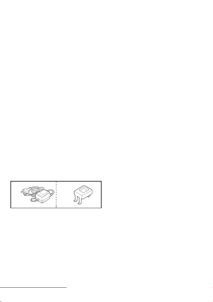
ACCESSORIES
1 AC adaptor......................................1 pc.
2 AC adaptor mounting plate ............1 pc.
: With 3 fixing screws
FEATURES
• Built-in interline transfer method 1/3"
CCD, approx. 320,000 picture elements
• Low smear, anti-blooming, low lag, no
burning and no geometric distortion
using the CCD solid state image device.
• 100% solid state components giving
excellent immunity to shock and
vibration
• Not subject to interference from
magnetic or electrostatic fields
• High sensitivity, minimum required
illumination of 0.31 lux with F2.0 lens
• Horizontal resolution, more than 400 TV
lines
• New backlight compensation function
(Active when using an auto-iris lens)
• Low power consumption and quick start
• Power supply: 12 V DC operation
(supplied AC adaptor)
• Built in Vari-focal (f=2.6 ~ 5.6 mm) auto
iris lens.
12
English 1
Page 3

PRECAUTIONS
In case of problem
Do not use the camera if smoke or a
strange odour comes from the unit, or if it
seems not to function correctly. Disconnect
the power cord immediately, and consult
your dealer (or a Sanyo Authorized Service
Centre).
Do not open or modify
Do not open the cabinet, as it may be
dangerous and cause damage to the unit.
For internal settings and repairs, consult
your dealer (or a Sanyo Authorized Service
Centre).
Do not put objects inside the unit
Make sure that no metal objects or
flammable substance get inside the camera.
If used with a foreign object inside, it could
cause a fire, short-circuits or damages.
If water or a liquid gets inside the camera,
disconnect the power cord immediately,
and consult your dealer (or a Sanyo
Authorized Service Centre). Be careful to
protect the camera from rain, sea water,
etc.
Be careful when handling the unit
To prevent damages, do not drop the
camera or subject it to strong shock or
vibration.
Install away from electric or
magnetic fields
If installed close to a TV, radio transmitter,
magnet, electric motor, transformer, audio
speakers the magnetic field they generate
will distort the image.
Protect from humidity and dust
To prevent damages to the camera, do not
install it where there is greasy smoke or
steam, where the dampness may get too
high, or where there is a lot of dust.
Protect from high temperatures
Do not install close to stoves, or other heat
generating devices, such as spotlights, etc.,
or where it could be subject to direct
sunlight, as that could cause deformation,
discoloration or other damages.
Be careful when installing close to the
ceiling, in a kitchen or boiler room, as the
temperature may raise to high levels.
Install where the temperature range will
stay between –10˚C and 50˚C.
(no condensation)
Cleaning
• Dirt can be removed from the cabinet
by wiping it with a soft cloth. To
remove stains, wipe with a soft cloth
moistened with a soft detergent
solution and wrung dry, then wipe dry
with dry soft cloth.
• Do not use benzine, thinner or other
chemical product on the cabinet, as that
may cause deformation and paint
peeling. Before using a chemical cloth,
make sure to read all accompanying
instructions. Make sure that no plastic
or rubber material comes in contact
with the cabinet for a long period of
time, as that may cause damage or
paint peeling.
ENGLISH
2 English
Page 4

PARTS NAMES
1 Video output connector (VIDEO OUT: BNC type)
Connect this connector to a device such as a VCR or monitor
1
2
5
6
8
1
1 Shorter screws: M3 x 4
2 Longer screws: M3 x 6
3 Camera mounting
screw hole:
1/4"-20 UNC
4
3
7
232
1
with a VIDEO IN connector.
2 12 V DC input terminal (12 V DC IN)
Connect DC connecting cord from the AC adaptor to the
12 V DC IN terminal on the camera.
3 External sync composite video signal input connector
Connect to this connector the synchronizing signal output
from a synchronizing signal device or the composite signal of
a video distributor.
4 Power indicator (POWER)
Comes on when the power to the camera is on.
5 Lens cover
This cover must be removed when adjusting the zoom
and/or the focus. (Refer to “LENS ADJUSTMENTS”.)
6 Focus ring
Loosen the knob on the focus ring then adjust it as required.
When finished, tighten the knob.
7 Zoom ring
Loosen the knob on the zoom ring then adjust it as required.
When finished, tighten the knob.
8 Camera installation bracket
The bracket can be fixed at the top or bottom of the
camera. When fixing the bracket, be sure to use the longer
screws and install the shorter screws on the opposite side to
seal the openings.
(VS IN: BNC type)
English 3
CAUTION:
When installing the camera support, select a location
that can support the total weight of the camera and
accessories.
Page 5

9 Camera setup section (under the cover)
This unit factory settings are as indicated below. However, if
due to installation conditions or environment the settings
may need to be modified for best results (see "SETTINGS").
To access the controls, remove the cover fixing screw, then
remove the cover.
9
a
OFF
BLC
b
VR401
L
E
V
E
L
LH
ON
LENS
DC
VIDEO
A. I.
Backlight compensation
a
switch (BLC)
Lens iris level volume
b
(LEVEL)
POWER SOURCE
Connect DC connecting cord from the AC adaptor to the
12V DC IN terminal on the camera.
Then, plug the AC adaptor into an AC outlet.
Control name Position
OFF
about centre
WARNING:
• This AC adaptor is specially conceived for this camera.
Never use another type of AC adaptor with this
camera, and do not use this AC adaptor to power
other types of cameras.
• Not for use with toys.
• Never try to disassemble or modify the AC adaptor.
4 English
Page 6

CONNECTIONS
(Video signal connections)
: VIDEO IN
: VIDEO OUT
(A)
Basic connection for monitoring or recording
The peripheral devices (VCR, monitor, lens, etc.) and
cables are sold separately.
Make the video signal connection between the camera and
the monitor or time lapse VCR.
Turn on the power of all the devices connected to the
camera.
When the power is connected to the camera, the POWER
indicator (A) will light. Adjust the picture on the monitor
using the Brightness and Contrast controls.
Coaxial cable type and maximum length
• Cable type RG-59U (3C-2V), 250 m maximum.
• Cable type RG-6U (5C-2V), 500 m maximum.
• Cable type RG-11U (7C-2V), 600 m maximum.
CAUTION:
• The RG-59U type cable should not be run through
electrical conduits or through the air.
• Using CCTV/Video-grade coaxial cable.
English 5
Page 7

SETTINGS
VR401
L
E
V
E
L
ON
OFF
BLC
LH
DC
VIDEO
A. I.
LENS
Backlight compensation setting
Set the BLC switch to the ON position, to engage the backlight
compensation function.
Note:
You will need to set the LEVEL (VR401) volume when shooting in
the conditions described below.
L (counterclockwise): To decrease the contrast
H (clockwise): To increase the contrast
• If shooting simultaneously in a dark room and through a bright
window.
• If the subject background is extremely bright or dark.
• If the brightness of the picture on the monitor is not correct.
LENS ADJUSTMENTS
OFF
BLC
VR401
LH
L
E
V
E
L
ON
3
1
After having installed the camera, adjust the lens zoom and
focus while looking at the image on the monitor screen.
1 Remove the lens cover by turning then pulling it as
illustrated.
2 Loosen the knob on the zoom ring then adjust it as
required by turning it towards T (zoom-in) or W
(zoom-out).
3 Loosen the knob on the focus ring then adjust it until the
image is clear by turning it towards N (near) or ∞
(infinity).
When the lens is properly adjusted, tighten the knob on
2
the zoom ring and the focus ring, then install the lens
cover to protect it.
6 English
Page 8

TROUBLESHOOTING
Before taking the camera for repairs, please check below to make sure that the camera is
used correctly. If it still does not perform correctly, please consult your dealer or a Sanyo
Authorized Service Centre.
No picture on the monitor screen
• Is the power turned on to all connected devices? Is the voltage correct?
• Are all the signal connecting cables correctly connected?
• Is the lighting sufficient?
The picture is not clear
• Is the monitor correctly adjusted?
• Is the lens focus correctly adjusted?
• Are the lens surfaces clean?
If there is dust or finger prints on the lens, the image quality will deteriorate. To clean the
lens use a soft cloth or a commercially available lens cleaning set.
SERVICE
This camera is a precision instruments and if treated with care, will provide years of
satisfactory performance. However, in the event of a problem, the owner is advised not to
attempt to make repairs or open the cabinet. Servicing should always be referred to your
dealer or Sanyo Authorized Service Centre.
English 7
Page 9

SPECIFICATIONS
Camera:
Scanning system : CCIR standard (625 TV lines, 25 frames/sec.)
Interlace : PLL 2:1 interlace
Image device : 1/3 inch solid state image device CCD
Effective picture elements : 512 (H) x 582 (V)
Minimum required illumination
Environmental conditions : Temperature: –10˚C ~ +50˚C
AC Adaptor:
Environmental conditions : Temperature: –10˚C ~ +50˚C
Picture elements : 542 (H) x 584 (V)
Synchronizing system : Internal sync/External sync (Automatic switching)
(incandescent lighting)
Backlight compensation : Manual ON/OFF switching, center zone light measuring
Power requirement : 12 V DC/130 mA
Power requirement : 220 – 230 V AC 50Hz
Power consumption : Approx. 3.0 W
Resolution : 400 TV lines horizontally, 400 TV lines vertically
Video output level : 1.0 Vp-p/75 ohms, composite
Video S/N ratio : More than 50 dB
Lens : F 2.0 ~ 2.7
Vari-focal lens : f = 2.6 ~ 5.6
Horizontal: Approx. 103˚ ~ 51˚
Vertical: Approx. 77˚ ~ 38˚
Diagonal: Approx. 128˚ ~ 64˚
: Scene: 0.31 lux, Image element: 0.016 lux
system (Active when using an auto-iris lens)
Gamma correction : γ = 0.45
Humidity: less than 90% (no condensation)
Power supply : 12 V DC (Supplied from AC adaptor)
Weight : Approx. 335 g
Humidity: less than 90 %
Weight : Approx. 440 g
8 English
Page 10

Dimensions: mm
8
18
146
11
95.5
1/4”–20 UNC
56
941.5
45
VIDEO OUT VS IN
12V DC IN
À
POWER
28
Approx. 1.8 m
75
Approx. 1.8 m
50
55
: mm
Features and specifications are subject to change without prior notice or obligations.
English 9
 Loading...