

Page 1
SERVICE MANUAL
FILE NO.
B/W CCD Camera
SPECIFICATIONS
Scanning system : CCIR standard (625 TV lines, 25 frames/sec.)
Interlace : PLL 2:1 interlace
Image device : 1/2 inch solid state image device CCD
Picture elements : 795 (Horizontal) x 596 (Vertical)
Effective picture elements : 752 (Horizontal) x 582 (Vertical)
Synchronizing system : Line lock/External sync (automatic switching)
Resolution : 560 TV lines horizontally, 350 TV lines vertically
Video output level : 1.0 Vp-p/75 W , composite
Video S/N ratio : More than 50 dB
Minimum required illumination : Approx. 0.02 lux with a F 1.2 lens,
(incandescent lighting) Approx. 0.03 lux with a F 1.4 lens
Backlight compensation : Manual ON/OFF switching, zone light measuring system
(Active when using an auto-iris lens)
Electronic iris function : Manual ON/OFF switching
Electronic iris range : 0.02 lux to 10,000 lux (F1.2, lens)
0.03 lux to 15,000 lux (F1.4, lens)
Flange-back : 12.5 mm ± 0.8 mm
Gamma correction : g = 0.45
Lens mount : CS mount (or C mount with the supplied adaptor)
Environmental conditions : Temperature: -10 °C ~ + 50 °C
Humidity: less than 90 % (no condensation)
Power supply : 24 V AC, (±4 V) 50 Hz
Power consumption : 3.1 W (with auto iris lens)
2.4 W (without auto iris lens)
Weight : Approx. 330 g (without lens)
VCB-3574IRP
(Product Code : 117 061 24)
(South East Asia)
(Europe)
CONTENTS
DISASSEMBLY, ADJUSTMENT, PARTS LIST.....FILE1
CIRCUIT DIAGRAMS
OVERALL WIRING, CA-1 CIRCUIT ...........FILE2
CA-2 CIRCUIT ............................................FILE3
CA-3 CIRCUIT ............................................FILE4
CA-4 CIRCUIT ............................................FILE5
CA-5 CIRCUIT ............................................FILE6
PRODUCT SAFETY NOTICE
The components designated by a symbol ( ! ) in this schematic diagram designates components whose value are of
special significance to product safety. Should any component designated by a symbol need to be replaced, use only the
part designated in the Parts List. Do not deviate from the resistance, wattage, and voltage ratings shown.
NOTE : 1. Parts order must contain model number, part number, and description.
2. Substitute parts may be supplied as the service parts.
3. N. S. P. : Not available as service parts.
Design and specification are subject to change without notice.
L72H4/XE
REFERENCE No. SM5310037
Page 2
SERVICE MANUAL
FILE NO.
B/W CCD Camera
SPECIFICATIONS
Scanning system : CCIR standard (625 TV lines, 25 frames/sec.)
Interlace : PLL 2:1 interlace
Image device : 1/2 inch solid state image device CCD
Picture elements : 795 (Horizontal) x 596 (Vertical)
Effective picture elements : 752 (Horizontal) x 582 (Vertical)
Synchronizing system : Line lock/External sync (automatic switching)
Resolution : 560 TV lines horizontally, 350 TV lines vertically
Video output level : 1.0 Vp-p/75 Ω, composite
Video S/N ratio : More than 50 dB
Minimum required illumination : Approx. 0.02 lux with a F 1.2 lens,
(incandescent lighting) Approx. 0.03 lux with a F 1.4 lens
Backlight compensation : Manual ON/OFF switching, zone light measuring system
(Active when using an auto-iris lens)
Electronic iris function : Manual ON/OFF switching
Electronic iris range : 0.02 lux to 10,000 lux (F1.2, lens)
0.03 lux to 15,000 lux (F1.4, lens)
Flange-back : 12.5 mm ± 0.8 mm
Gamma correction : γ = 0.45
Lens mount : CS mount (or C mount with the supplied adaptor)
Environmental conditions : Temperature: -10 °C ~ + 50 °C
Humidity: less than 90 % (no condensation)
Power supply : 24 V AC, (±4 V) 50 Hz
Power consumption : 3.1 W (with auto iris lens)
2.4 W (without auto iris lens)
Weight : Approx. 330 g (without lens)
VCB-3574IRP
(Product Code : 117 061 24)
(South East Asia)
(Europe)
CONTENTS
1. DISASSEMBLY ....................................2
2. BOARD LOCATION .............................3
3. ADJUSTMENT .....................................4
4. PARTS LIST .........................................6
SCHEMATIC DIAGRAM
PRODUCT SAFETY NOTICE
The components designated by a symbol ( ! ) in this schematic diagram designates components whose value are of
special significance to product safety. Should any component designated by a symbol need to be replaced, use only the
part designated in the Parts List. Do not deviate from the resistance, wattage, and voltage ratings shown.
NOTE : 1. Parts order must contain model number, part number, and description.
2. Substitute parts may be supplied as the service parts.
3. N. S. P. : Not available as service parts.
Design and specification are subject to change without notice.
L72H4/XE
REFERENCE No. SM5310037
Page 3
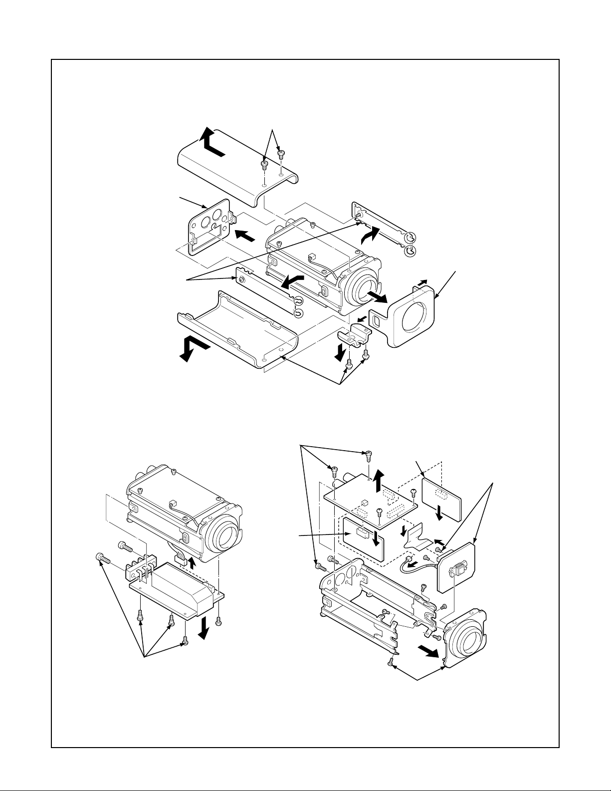
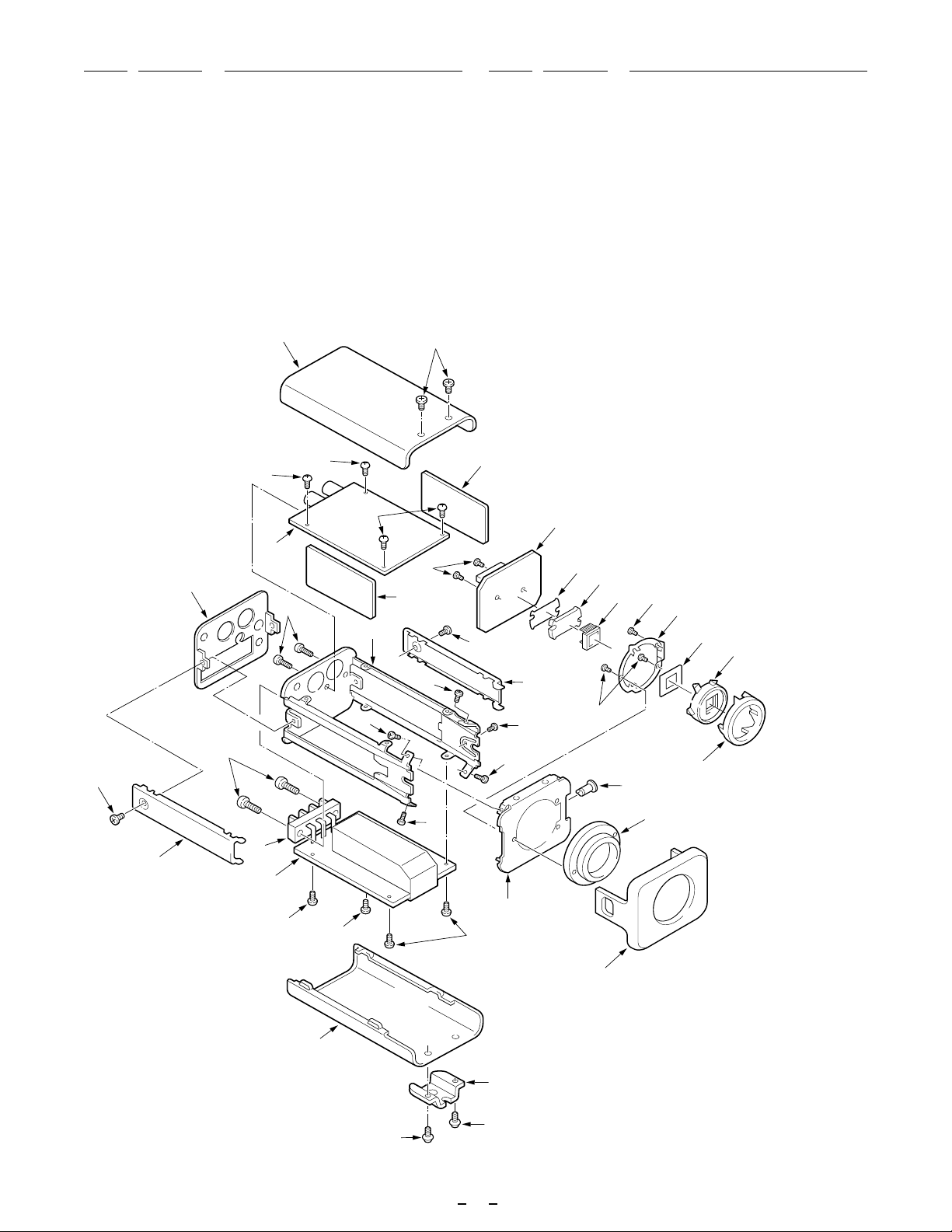
1. DISASSEMBLY
2. Remove the rear panel.
3. Remove the two screws,
and then pull out the top cabinet.
1. Loosen the two screws,
and then remove the left
and right side panels.
4. Remove the two screws, and then remove
the bracket and pull out the bottom cabinet.
7. Remove the six screws, then remove
the CA-2/CA-3/CA-4 board assemblies
and the FPC, and disconnect the connector.
CA-3 board
CA-2 board
CA-4
board
5. Remove the front panel.
9. Remove the two
screws, and then
remove the CA-1
board assembly.
CA-5 board
6. Remove the six screws, and then
disconnect the CA-5 board assembly
connector from the CA-2 board assembly.
CA-1 board
8. Remove the five screws, and then
remove the lens mount bracket.
-2-
Page 4

2. BOARD LOCATION
TP101
TP102
CA-1 board (Side A)
VR201
VR203
SUB
RGL
Abbr.
TP202
SUB
RGL
Abbr.
TP201
VR204
TP301
CT301
CA-3 board (Side A)
VR401
SW401
SW402
VR502
CA-2 board (Side B)
TP501
TP502
CN206
SW403
CA-4 board (Side A)
CA-2 board
CA-3 board
CA-5 board
CA-4 board
VR501
CA-1 board
CA-5 board (Side A)
-3-
Page 5
3. ADJUSTMENT
3-1. ADJUSTMENT PREPARATION
1. Set the ITE gray scale chart II(γ =0.45) to the viewer.
2. Set the angle of adjustment control (VR) before starting
adjustment at the center or temporary adjustment (nearly
adjusted) unless specified.
3. Set the trigger signal of oscilloscope to VIDEO OUT, and
apply H sync unless specified.
4. Set the operating condition of the camera (switch settings
inside the side panel) as follows in adjusting unless specified.
E.l./BLC switch (SW402): "OFF" position
Auto iris switch (SW401): "DC" position
5. The VIDEO OUT connector connect to a video monitor terminated in 75 Ω input impedance.
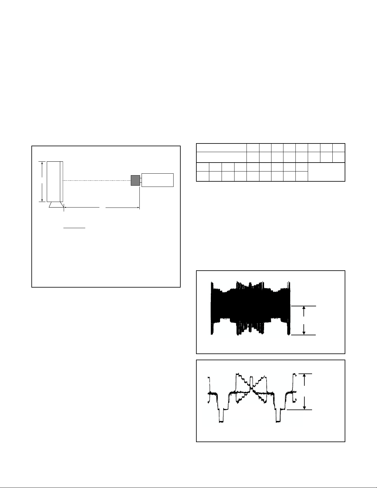
3,100 K viewer
CCD camera
H
L
2
(H + h)
L = × f 12.5 mm
H× h
L: Distance from CS mount to pattern (mm)
H: Pattern height (mm)
f: Lens focal length (standard 12 mm)
h: Height (4.8 mm) of CCD imaging surface
CS mount surface
3-4. SUB Voltage Adjustment
Adjustment location: VR201 (CA-2)
Measuring location: TP102 (CA-1)
Measuring equipment: Digital voltmeter
Subject: No designation
Adjusting method:
1. Read SUB voltage from the abbreviation described on the
side A of CA-1 board.
2. Adjust with VR201 to the adjustment value.
Note:
Note that the adjustment value depends on CCD imager.
When installing a new CCD, read the abbreviation described
on the rear side of CCD and write it to the board.
SUB voltage value ± 0.1 V (below figure)
E
VSUB abbreviation
SUB voltage (V)
P
N
10.0
10.5
Q
11.0R11.5
6.0
S
12.0
f
6.5G7.0
T
12.5
U
13.0
h
7.5J8.0
V
14.0
13.5
W
K
8.5
L
9.0
m
9.5
3-5. AGC LEVEL ADJUSTMENT
Adjustment location: VR203 (CA-2)
Measuring location: TP202 (CA-2), VIDEO OUT
Measuring equipment: Oscilloscope
Subject: Gray scale chart
Adjusting method:
1. Adjust the lens aperture so that the waveform level of TP202
is 400 ± 50 mVp-p.
2. Adjust with VR203 so that the waveform level is 800 ± 10
mVp-p during video output.
Note : The video monitor should be an under-scan TV.
3-2. Power Supply Voltage Adjustment
Adjustment location: VR501 (CA-5)
Measuring location:
Measuring equipment: Digital voltmeter
Subject: No designation
Adjusting method:
1. Adjust with VR501 to 5.00 ± 0.05 V DC.
TP502 (CA-5)
3-3. Oscillation Control Voltage Adjustment
Adjustment location: CT301 (CA-3)
Measuring location: TP301 (CA-3)
Measuring equipment: Digital voltmeter, Standard signal
generator (for external sync)
Subject: No designation
Adjusting method:
1. Input the standard signal for external sync to CN206.
2. Adjust with CT301 to 3.00 ± 0.05 V.
400 ± 50 mVp-p
TP202
800 ± 10 mVp-p
VIDEO OUTPUT
-4-
Page 6
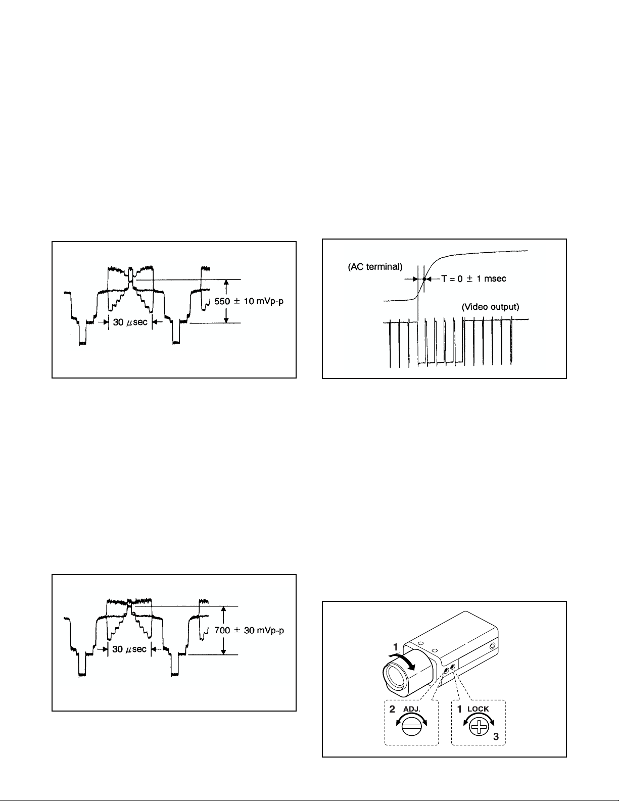
3-6. Auto Iris Level Adjustment
Adjustment location: SW401, SW402, VR401 (CA-4)
Measuring location: VIDEO OUT
Measuring equipment: Oscilloscope
Subject: Gray scale chart
Preparation:
1. Auto iris switch (SW401) : “DC” position
BLC switch (SW402) : “OFF” position
2. Attach the automatic iris lens, and then adjust the distance
between the camera and the subject so that the gray scale
waveform width is 30 µsec. (Refer to the figure below.)
Adjusting method:
1. Turn VR401 clockwise as far as it will go. (The white level
will become distorted.)
2. Turn VR401 counterclockwise untill the waveform level is
550 ± 10 mVp-p during video output.
3-8. Line Phase Adjustment
Adjustment location: VR502 (CA-5)
Measuring location: VIDEO OUT, 24 V AC terminals
Measuring equipment: Oscilloscope
Subject: Gray scale chart
Preparation:
1. Set the oscilloscope synchronization to vertical synchronization.
2. Connect the oscilloscope probe to the right side of the 24 V
AC terminals, and then connect the probe GND to the left
side of the 24 V AC terminals.
Adjusting method:
1. Turn VR502 to adjust so that the phase difference between
the leading edge of the vertical synchronization signal of
the video output and the zero-cross point of the 24 V AC
line waveform is 0 ± 1 msec.
VIDEO OUTPUT
3-7. Backlight Compensation Adjustment
Adjustment location: VR204 (CA-2), SW402
Measuring location: VIDEO OUT
Measuring equipment: Oscilloscope
Subject: Gray scale chart
Preparation:
1. BLC switch (SW402) : “ON” position
2. Attach the automatic iris lens, and then adjust the distance
between the camera and the subject so that the gray scale
waveform width is 30 µsec. (Refer to the figure below.)
Adjustment method:
1. Adjust with VR204 so that the waveform level is 700 ± 30
mVp-p during video output.
2. Return the BLC switch (SW402) to the “OFF” position.
3-9. Flange-back Adjustment
Adjustment location: Flange back adj. screw
Measuring location: Monitor display
Measuring equipment: Video monitor
Subject: Siemens star chart
Preparation:
1. Attach the zoom lens.
Adjusting method:
1. Using a + screwdriver, loosen the FLANGE BACK LOCK
screw. Set the zoom lens to the maximum telephoto position, and set the focus using on the lens.
2. Set the zoom lens to the maximum wide angle position, and
set the focus using the FLANGE BACK ADJ. screw.
3. Repeat steps 2. and 3. until the image stays in focus when
changing from a telephoto shot to a wide angle shot.
When the setting is complete, tighten the FLANGE BACK
LOCK screw.
VIDEO OUTPUT
-5-
Page 7
4. PARTS LIST
CABINET & CHASSIS PARTS
1 613 159 9369 DEC INDICATOR
2 613 156 4015 COVER BOTTOM
3 412 051 6007 SPECIAL SCREW-3X4
4 613 159 2797 MOUNTING
5 411 126 4702 SCR PAN+SW+W 3X6
6 411 164 7703 SCR TRS+IN TW 2X5
7 613 156 3971 CABINET FRONT
8 613 186 2548 COMPL PWB,CA-5
9 412 054 3805 SPECIAL SCREW-2.0X4.0
10 613 185 3782 COVER SIDE-L
11 613 185 3775 COVER SIDE-R
12 411 126 1404 SCR S-TPG BIN 2X4
13 411 023 4201 SCR S-TPG PAN 3X10
14 613 186 2517 COMPL PWB,CA-2
LOCATION PARTS NO. DESCRIPTIONLOCATION PARTS NO. DESCRIPTION
15 613 186 2524 COMPL PWB,CA-3
16 613 185 4413 COMPL PWB,CA-4
17 411 021 0809 SCR S-TPG BIN 2X6
18 613 185 4383 COMPL PWB,CA-1
19 613 158 6369 SPACER INSULATOR
20 613 156 4374 HOLDER CCD
21 409 441 3807 IC ICX249AL-7 (IC101)
22 613 156 4091 MOUNTING,LENS
23 613 161 8350 CAM
24 613 156 4114 SLIDE
25 613 156 4695 HOUSING CCD
26 613 156 4442 SPRING PLATE
27 411 125 8503 SCR PAN PCS 2X4
28 613 156 4411 SPACER
29 645 004 9347 TERMINAL,BOARD (CN502)
30 411 045 2407 SCR PAN+SW 3X10
2
6
3
15
6
6
18
14
17
1
16
13
N.S.P.
12
12
30
9
11
9
12
9
19
27
20
21
23
27
26
28
25
24
10
L72H4/US
29
12
22
8
N.S.P.
6
6
6
7
2
4
5
5
6
Page 8

ELECTRICAL PARTS
Note:
1. Materials of Capacitors and Resistors are abbreviated as follows ;
Resistors Capacitors
MT-FILM Metallized Film Resistor MT-POLYEST Metallized Polyester Capacitor
MT-GLAZE Metallized Glaze Resistor MT-COMPO Metallized Composite Capacitor
OXIDE-MT Oxide Metallized Film Resistor TA-SOLD Tantalum Solid Capacitor
AL-SOLID Aluminum Solid Capacitor
NP-ELECT Non-Polarized Electrolytic Capacitor
OS-SOLID Aluminum Solid Capacitors with Organic
Semiconductive Electrolytic Capacitor
2. Tolerance of Capacitor (10pF over) and Resistor are noted with follow symboles.
F ............1% G ............2% J ............5% K ............10%
M ..........20% N ..........30% Z ..........+80% ~ -20%
3. Capacitors
µ
F P : pF
U :
4. Inductors
µ
H MH : mH
UH :
5. N.S.P. : Not available as service parts.
LOCATION PARTS NO. DESCRIPTION LOCATION PARTS NO. DESCRIPTION
COMPL PWB,CA-1
613 185 4383
DL-ELECT Double Layered Electrolytic Capacitor
(CONNECTOR)
CN101 645 007 7074 SOCKET,FPC 20P (N.S.P)
Q1001 405 090 4905 TR 2SC4452-4
(SEMICONDUCTORS)
Q1002 405 100 3201 TR 2SA1763
Q1003 405 100 3201 TR 2SA1763
Q1004 405 090 4905 TR 2SC4452-4
Q1006 405 045 8200 TR 2SK443-6-TB
Q1007 405 079 6302 TR 2SC4399-5
(INTEGRATED CIRCUITS)
IC102 409 366 9700 IC CXD1267AN
IC103 409 331 5003 IC TC74AC04FS
(DIODES)
D1001 407 113 5609 DIODE DSH015
D1002 407 113 5609 DIODE DSH015
D1003 407 113 5609 DIODE DSH015
D1004 407 113 5609 DIODE DSH015
D1005 407 113 5609 DIODE DSH015
D1006 407 113 5609 DIODE DSH015
(CAPACITORS)
C1001 403 164 0204 CERAMIC 0.1U Z 25V
C1002 403 164 0204 CERAMIC 0.1U Z 25V
C1003 403 164 0204 CERAMIC 0.1U Z 25V
C1004 403 164 0204 CERAMIC 0.1U Z 25V
C1005 403 164 0204 CERAMIC 0.1U Z 25V
C1006 403 164 0204 CERAMIC 0.1U Z 25V
C1007 403 285 6406 TA-SOLID 1U M 35V
C1008 403 164 0204 CERAMIC 0.1U Z 25V
C1009 403 164 0204 CERAMIC 0.1U Z 25V
C1011 403 145 9905 CERAMIC 22P J 50V
C1012 403 155 1500 CERAMIC 180P J 50V
C1013 403 164 0204 CERAMIC 0.1U Z 25V
C1016 403 164 0204 CERAMIC 0.1U Z 25V
C1018 403 175 4505 ELECT 47U M 6.3V
C1019 403 285 5003 TA-SOLID 1U M 25V
C1021 403 285 4402 TA-SOLID 3.3U M 16V
C1022 403 175 4109 ELECT 22U M 16V
C1023 403 285 4808 TA-SOLID 3.3U M 20V
(RESISTORS)
R1001 401 105 0702 MT-GLAZE 100K JA 1/16W
R1002 401 105 8005 MT-GLAZE 1M JA 1/16W
R1003 401 105 8005 MT-GLAZE 1M JA 1/16W
R1006 401 105 0306 MT-GLAZE 10 JA 1/16W
R1007 401 105 0306 MT-GLAZE 10 JA 1/16W
R1008 401 105 0306 MT-GLAZE 10 JA 1/16W
R1009 401 105 4502 MT-GLAZE 390 JA 1/16W
R1011 401 105 0405 MT-GLAZE 100 JA 1/16W
R1012 401 105 3406 MT-GLAZE 27K JA 1/16W
R1013 401 105 2201 MT-GLAZE 180K JA 1/16W
R1014 401 105 4601 MT-GLAZE 3.9K JA 1/16W
R1015 401 105 7909 MT-GLAZE 0.000 ZA 1/16W
R1016 401 105 3307 MT-GLAZE 2.7K JA 1/16W
COMPL PWB,CA-2
613 186 2517
(SEMICONDUCTORS)
Q2003 405 077 3402 TR 2SC4211-6
OR 405 047 5900 TR 2SD1622-S
Q2004 405 047 6006 TR 2SD1622-T
Q2005 405 077 3402 TR 2SC4211-6
Q2006 405 077 3402 TR 2SC4211-6
Q2007 405 077 2207 TR 2SA1622-6
Q2008 405 077 3402 TR 2SC4211-6
Q2009 405 077 2207 TR 2SA1622-6
(INTEGRATED CIRCUITS)
IC201 409 302 5308 IC CXD1255Q
IC202 409 183 2007 IC CXD1159Q
IC203 409 281 3906 IC CXA1310AQ
IC204 409 142 2000 IC LA6358NM
IC207 409 155 7900 IC TC7S02F
IC208 409 155 8006 IC TC7S04F
IC209 409 155 8006 IC TC7S04F
IC211 409 137 9007 IC TC4S81F
(DIODES)
D2001 407 065 3906 LED SLP-135B-51,
D2002 407 070 9702 ZENER DIODE DZD11Y
D2004 407 070 9702 ZENER DIODE DZD11Y
D2005 407 070 9702 ZENER DIODE DZD11Y
D2006 407 113 5609 DIODE DSH015
D2007 407 113 5609 DIODE DSH015
D2008 407 113 5609 DIODE DSH015
D2009 407 113 5609 DIODE DSH015
D2011 407 113 5609 DIODE DSH015
(VARIABLE RESISTORS)
VR201 645 003 6781 VR,SEMI,47K N
VR203 645 003 8648 VR,SEMI,1K N
VR204 645 003 6781 VR,SEMI,47K N
(INDUCTORS)
L2001 645 003 9386 INDUCTOR,10U J
L2002 645 003 9386 INDUCTOR,10U J
L2003 645 003 9522 INDUCTOR,33U J
L2004 645 003 9522 INDUCTOR,33U J
L2005 645 007 6855 INDUCTOR,1.5U J
L2006 645 007 6664 INDUCTOR,6.8U J
(CAPACITORS)
C2001 403 175 3300 ELECT 47U M 16V
C2002 403 248 9703 ELECT 10U M 16V
C2003 403 285 4006 TA-SOLID 4.7U M 10V
C2004 403 155 1807 CERAMIC 0.01U K 25V
C2005 403 164 0204 CERAMIC 0.1U Z 25V
C2006 403 157 2901 CERAMIC 47P J 50V
7
Page 9

LOCATION PARTS NO. DESCRIPTION LOCATION PARTS NO. DESCRIPTION
C2008 403 258 4200 ELECT 22U M 6.3V
C2012 403 164 0204 CERAMIC 0.1U Z 25V
C2013 403 276 7405 TA-SOLID 10U M 6.3V
C2014 403 285 3603 TA-SOLID 4.7U M 6.3V
C2015 403 164 0204 CERAMIC 0.1U Z 25V
C2016 403 157 2901 CERAMIC 47P J 50V
C2017 403 157 2901 CERAMIC 47P J 50V
C2018 403 155 1807 CERAMIC 0.01U K 25V
C2019 403 258 4200 ELECT 22U M 6.3V
C2022 403 157 2901 CERAMIC 47P J 50V
C2023 403 285 6901 TA-SOLID 22U M 6.3V
C2024 403 155 1807 CERAMIC 0.01U K 25V
C2025 403 157 2901 CERAMIC 47P J 50V
C2026 403 285 7304 TA-SOLID 2.2U M 16V
C2027 403 285 7304 TA-SOLID 2.2U M 16V
C2028 403 207 0307 CERAMIC 1U Z 16V
C2029 403 164 0204 CERAMIC 0.1U Z 25V
C2031 403 157 3106 CERAMIC 56P J 50V
C2032 403 285 5003 TA-SOLID 1U M 25V
C2033 403 155 1807 CERAMIC 0.01U K 25V
C2034 403 285 7502 TA-SOLID 0.1U M 35V
C2035 403 145 9905 CERAMIC 22P J 50V
C2036 403 145 9905 CERAMIC 22P J 50V
C2037 403 248 9703 ELECT 10U M 16V
C2038 403 248 9703 ELECT 10U M 16V
C2039 403 157 3601 CERAMIC 100P J 50V
C2041 403 155 1807 CERAMIC 0.01U K 25V
C2042 403 155 1807 CERAMIC 0.01U K 25V
C2043 403 258 4200 ELECT 22U M 6.3V
C2044 403 157 3601 CERAMIC 100P J 50V
C2045 403 157 2505 CERAMIC 27P J 50V
C2046 403 155 1807 CERAMIC 0.01U K 25V
C2048 403 175 0606 ELECT 100U M 6.3V
C2049 403 276 7405 TA-SOLID 10U M 6.3V
C2051 403 164 0204 CERAMIC 0.1U Z 25V
C2052 403 164 0204 CERAMIC 0.1U Z 25V
C2055 403 164 0204 CERAMIC 0.1U Z 25V
C2056 403 164 0204 CERAMIC 0.1U Z 25V
C2078 403 113 3805 CERAMIC 1000P K 50V
C2079 403 164 0204 CERAMIC 0.1U Z 25V
C2081 403 164 0204 CERAMIC 0.1U Z 25V
C2082 403 276 7405 TA-SOLID 10U M 6.3V
C2084 403 157 2901 CERAMIC 47P J 50V
C2085 403 258 4200 ELECT 22U M 6.3V
C2086 403 068 0409 CERAMIC 0.1U Z 25V
C2087 403 172 6106 CERAMIC 270P J 50V
(RESISTORS)
R2002 401 105 0405 MT-GLAZE 100 JA 1/16W
R2003 401 105 0405 MT-GLAZE 100 JA 1/16W
R2004 401 166 9508 MT-FILM 4.7K DU 1/16W
R2005 401 166 3100 MT-FILM 22K DU 1/ 16W
R2006 401 167 0702 MT-FILM 15K DU 1/ 16W
R2007 401 167 1709 MT-FILM 47K DD 1/ 16W
R2009 401 166 3209 MT-FILM 39K DD 1/ 16W
R2011 401 167 0306 MT-FILM 10K DU 1/ 16W
R2012 401 166 3209 MT-FILM 39K DD 1/16W
R2013 401 166 9508 MT-FILM 4.7K DU 1/16W
R2014 401 166 3209 MT-FILM 39K DD 1/16W
R2015 401 105 0603 MT-GLAZE 10K JA 1/16W
R2016 401 177 2703 MT-GLAZE 6.8 JA 1/16W
R2017 401 105 7909 MT-GLAZE 0.000 ZA 1/16W
R2018 401 105 0603 MT-GLAZE 10K JA 1/16W
R2019 401 105 4205 MT-GLAZE 33K JA 1/16W
R2021 401 105 2805 MT-GLAZE 2.2K JA 1/16W
R2022 401 105 7909 MT-GLAZE 0.000 ZA 1/16W
R2024 401 105 2805 MT-GLAZE 2.2K JA 1/16W
R2026 401 105 7909 MT-GLAZE 0.000 ZA 1/16W
R2027 401 105 2805 MT-GLAZE 2.2K JA 1/16W
R2028 401 105 2805 MT-GLAZE 2.2K JA 1/16W
R2029 401 105 2805 MT-GLAZE 2.2K JA 1/16W
R2031 401 105 8005 MT-GLAZE 1M JA 1/16W
R2032 401 105 0603 MT-GLAZE 10K JA 1/16W
R2034 401 037 5004 MT-GLAZE 0.000 ZA 1/10W
R2035 401 167 0306 MT-FILM 10K DU 1/16W
R2036 401 167 0702 MT-FILM 15K DU 1/16W
R2038 401 037 5004 MT-GLAZE 0.000 ZA 1/10W
R2039 401 037 5004 MT-GLAZE 0.000 ZA 1/10W
R2041 401 166 8105 MT-FILM 1K DU 1/16W
R2043 401 105 4205 MT-GLAZE 33K JA 1/16W
R2044 401 105 6001 MT-GLAZE 5.6K JA 1/16W
R2045 401 166 8105 MT-FILM 1K DU 1/16W
R2046 401 166 7108 MT-FILM 390 DU 1/16W
R2047 401 105 2805 MT-GLAZE 2.2K JA 1/16W
R2048 401 166 8105 MT-FILM 1K DU 1/16W
R2049 401 166 3100 MT-FILM 22K DU 1/16W
R2051 401 105 0504 MT-GLAZE 1K JA 1/16W
R2052 401 105 1501 MT-GLAZE 1.5K JA 1/16W
R2053 401 105 3307 MT-GLAZE 2.7K JA 1/16W
R2054 401 167 0306 MT-FILM 10K DU 1/16W
R2055 401 166 3209 MT-FILM 39K DD 1/16W
R2056 401 105 0702 MT-GLAZE 100K JA 1/16W
R2057 401 105 0603 MT-GLAZE 10K JA 1/16W
R2058 401 105 0504 MT-GLAZE 1K JA 1/16W
R2059 401 105 6001 MT-GLAZE 5.6K JA 1/16W
R2061 401 105 0405 MT-GLAZE 100 JA 1/16W
R2062 401 105 0603 MT-GLAZE 10K JA 1/16W
R2063 401 105 0603 MT-GLAZE 10K JA 1/16W
R2064 401 105 6407 MT-GLAZE 68 JA 1/16W
R2065 401 105 0504 MT-GLAZE 1K JA 1/16W
R2068 401 166 7306 MT-FILM 470 DU 1/16W
R2069 401 037 5004 MT-GLAZE 0.000 ZA 1/10W
R2070 401 113 4402 MT-GLAZE 75 JA 1/16W
R2071 401 105 5400 MT-GLAZE 47K JA 1/16W
R2072 401 105 4205 MT-GLAZE 33K JA 1/16W
R2073 401 105 0504 MT-GLAZE 1K JA 1/16W
R2074 401 166 9508 MT-FILM 4.7K DU 1/16W
R2075 401 166 7306 MT-FILM 470 DU 1/16W
R2076 401 113 9506 MT-GLAZE 620K JA 1/16W
(CONNECTORS)
CN201 645 007 6503 PLUG,2P (N.S.P)
CN202 645 007 7074 SOCKET,FPC 20P (N.S.P)
CN203 645 008 5444 PLUG,18P (N.S.P)
CN204 645 008 5437 PLUG,16P (N.S.P)
CN205 645 004 9231 SOCKET,BNC 1P (N.S.P)
CN206 645 004 9231 SOCKET,BNC 1P (N.S.P)
(MISCELLANEOUS)
636 032 8907 SPACER
COMPL PWB,CA-3
613 186 2524
(SEMICONDUCTOR)
Q3001 405 078 7003 TR 2SC4397
(INTEGRATED CIRCUITS)
IC301 409 285 2202 IC LC9105B-705
IC302 409 330 9606 IC TC7SHU04FU
IC303 409 330 9606 IC TC7SHU04FU
IC304 409 251 0300 IC TC7W04F
IC305 409 051 3402 IC TC4066BF
IC306 409 341 3402 IC NJM2257M
(DIODE)
D3001 407 113 5609 DIODE DSH015
(VARIABLE CAPACITOR)
VC301 407 160 4709 VA MA366(E)-SAN1
(TRIMMER)
CT301 645 004 2829 TRIMMER,20PF
(INDUCTORS)
L3001 645 003 9546 INDUCTOR,47U J
L3002 645 007 6855 INDUCTOR,1.5U J
(CAPACITORS)
C3001 403 207 0307 CERAMIC 1U Z 16V
C3002 403 174 6708 NP-ELECT 4.7U M 16V
C3003 403 155 1807 CERAMIC 0.01U K 25V
C3004 403 155 1807 CERAMIC 0.01U K 25V
C3005 403 155 1807 CERAMIC 0.01U K 25V
C3006 403 285 7205 TA-SOLID 3.3U M 10V
C3007 403 164 0204 CERAMIC 0.1U Z 25V
C3008 403 155 1807 CERAMIC 0.01U K 25V
C3009 403 157 1805 CERAMIC 9P D 50V
C3011 403 113 3805 CERAMIC 1000P K 50V
C3013 403 164 0204 CERAMIC 0.1U Z 25V
C3014 403 285 3603 TA-SOLID 4.7U M 6.3V
C3015 403 145 9905 CERAMIC 22P J 50V
C3017 403 157 1805 CERAMIC 9P D 50V
C3018 403 113 3805 CERAMIC 1000P K 50V
8
Page 10

LOCATION PARTS NO. DESCRIPTION
C3019 403 113 3805 CERAMIC 1000P K 50V
C3020 403 164 0204 CERAMIC 0.1U Z 25V
C3021 403 113 3805 CERAMIC 1000P K 50V
C3022 403 207 0307 CERAMIC 1U Z 16V
C3024 403 281 5205 CERAMIC 0.22U Z 16V
C3025 403 113 3805 CERAMIC 1000P K 50V
C3026 403 164 0204 CERAMIC 0.1U Z 25V
C3028 403 113 3805 CERAMIC 1000P K 50V
C3029 403 215 0900 CERAMIC 390P J 50V
C3031 403 113 3805 CERAMIC 1000P K 50V
(RESISTORS)
R3001 401 105 4205 MT-GLAZE 33K JA 1/16W
R3002 401 105 7503 MT-GLAZE 82K JA 1/16W
R3003 401 105 4700 MT-GLAZE 39K JA 1/16W
R3004 401 105 4700 MT-GLAZE 39K JA 1/16W
R3006 401 105 7909 MT-GLAZE 0.000 ZA 1/16W
R3008 401 105 5905 MT-GLAZE 560 JA 1/16W
R3009 401 167 1709 MT-FILM 47K DD 1/16W
R3011 401 105 6605 MT-GLAZE 6.8K JA 1/16W
R3012 401 167 0306 MT-FILM 10K DU 1/16W
R3014 401 105 7909 MT-GLAZE 0.000 ZA 1/16W
R3016 401 105 8005 MT-GLAZE 1M JA 1/16W
R3017 401 105 0702 MT-GLAZE 100K JA 1/16W
R3018 401 105 0504 MT-GLAZE 1K JA 1/16W
R3019 401 105 0702 MT-GLAZE 100K JA 1/16W
R3020 401 105 0504 MT-GLAZE 1K JA 1/16W
R3021 401 105 7909 MT-GLAZE 0.000 ZA 1/16W
R3022 401 105 7404 MT-GLAZE 8.2K JA 1/16W
R3023 401 105 5301 MT-GLAZE 4.7K JA 1/16W
R3024 401 105 2805 MT-GLAZE 2.2K JA 1/16W
R3025 401 113 8202 MT-GLAZE 51K JA 1/16W
R3026 401 105 0702 MT-GLAZE 100K JA 1/16W
R3027 401 105 6001 MT-GLAZE 5.6K JA 1/16W
R3028 401 105 6001 MT-GLAZE 5.6K JA 1/16W
R3029 401 105 6001 MT-GLAZE 5.6K JA 1/16W
R3031 401 167 1709 MT-FILM 47K DD 1/16W
R3032 401 105 0702 MT-GLAZE 100K JA 1/16W
R3045 401 105 7909 MT-GLAZE 0.000 ZA 1/16W
(CONNECTOR)
CN301 645 007 7203 SOCKET,18P (N.S.P)
COMPL PWB,CA-4
613 185 4413
(SEMICONDUCTORS)
Q4003 405 015 8704 TR 2SC2812-L6
Q4004 405 015 8704 TR 2SC2812-L6
Q4005 405 015 8704 TR 2SC2812-L6
Q4006 405 002 6706 TR 2SA1179-M6
Q4007 405 002 6706 TR 2SA1179-M6
Q4008 405 018 2006 TR 2SC3396
Q4009 405 015 8704 TR 2SC2812-L6
Q4011 405 015 8704 TR 2SC2812-L6
(INTEGRATED CIRCUITS)
IC401 409 051 2900 IC TC4053BF
IC402 409 142 2000 IC LA6358NM
IC403 409 039 6302 IC NJM2903M
IC404 409 155 7702 IC TC4S66F
(DIODES)
D4002 407 004 8009 DIODE DSB015
(VARIABLE RESISTORS)
VR401 645 004 7244 VR,SEMI,10K S
(CAPACITORS)
C4001 403 069 1702 CERAMIC 1000P K 50V
C4002 403 069 1702 CERAMIC 1000P K 50V
C4003 403 069 1702 CERAMIC 1000P K 50V
C4004 403 285 4907 TA-SOLID 0.47U M 25V
C4005 403 285 7205 TA-SOLID 3.3U M 10V
C4006 403 068 0409 CERAMIC 0.1U Z 25V
C4007 403 175 3300 ELECT 47U M 16V
C4008 403 172 6502 NP-ELECT 0.47U M 50V
C4011 403 068 0409 CERAMIC 0.1U Z 25V
C4012 403 285 4006 TA-SOLID 4.7U M 10V
C4013 403 068 0409 CERAMIC 0.1U Z 25V
C4014 403 207 0307 CERAMIC 1U Z 16V
C4015 403 068 0409 CERAMIC 0.1U Z 25V
LOCATION PARTS NO. DESCRIPTION
(RESISTORS)
R4005 401 037 5400 MT-GLAZE 1K JA 1/10W
R4006 401 038 6406 MT-GLAZE 4.7K JA 1/10W
R4008 401 164 7803 MT-FILM 2.7K DU 1/10W
R4009 401 038 3504 MT-GLAZE 330 JA 1/10W
R4011 401 038 3504 MT-GLAZE 330 JA 1/10W
R4012 401 037 5806 MT-GLAZE 1M JA 1/10W
R4013 401 038 0800 MT-GLAZE 22K JA 1/10W
R4014 401 038 7700 MT-GLAZE 5.6K JA 1/10W
R4015 401 038 6406 MT-GLAZE 4.7K JA 1/10W
R4016 401 038 6406 MT-GLAZE 4.7K JA 1/10W
R4017 401 038 3702 MT-GLAZE 33K JA 1/10W
R4018 401 037 6704 MT-GLAZE 1.2K JA 1/10W
R4019 401 037 8005 MT-GLAZE 15K JA 1/10W
R4021 401 037 5004 MT-GLAZE 0.000 ZA 1/10W
R4022 401 037 5004 MT-GLAZE 0.000 ZA 1/10W
R4026 401 037 5608 MT-GLAZE 10K JA 1/10W
R4027 401 038 6406 MT-GLAZE 4.7K JA 1/10W
R4028 401 037 5400 MT-GLAZE 1K JA 1/10W
R4029 401 037 5806 MT-GLAZE 1M JA 1/10W
R4031 401 038 6406 MT-GLAZE 4.7K JA 1/10W
R4032 401 037 5608 MT-GLAZE 10K JA 1/10W
R4033 401 037 5004 MT-GLAZE 0.000 ZA 1/10W
R4034 401 038 0800 MT-GLAZE 22K JA 1/10W
R4035 401 037 5608 MT-GLAZE 10K JA 1/10W
R4036 401 164 7407 MT-FILM 1.8K DU 1/10W
SW401 645 033 1404 SWITCH,SLIDE 4P-2T,
SW402 645 002 0551 SWITCH,SLIDE 2P-3T,
(CONNECTORS)
CN401 645 007 7197 SOCKET,16P (N.S.P)
CN402 645 004 9293 SOCKET,4P (N.S.P)
COMPL PWB,CA-5
613 186 2548
(SEMICONDUCTORS)
Q5001 405 015 8704 TR 2SC2812-L6
Q5002 405 015 8704 TR 2SC2812-L6
Q5003 405 002 6706 TR 2SA1179-M6
Q5004 405 047 5900 TR 2SD1622-S
OR 405 047 6006 TR 2SD1622-T
Q5005 405 015 8704 TR 2SC2812-L6
Q5006 405 002 6706 TR 2SA1179-M6
Q5007 405 015 8704 TR 2SC2812-L6
Q5008 405 048 4605 TR 2SD1816-S
Q5009 405 048 0805 TR 2SB1216S
OR 405 048 1000 TR 2SB1216T
(INTEGRATED CIRCUITS)
IC501 409 196 7006 IC FA7612N
IC502 409 167 7202 IC NJM2406F
(DIODES)
D5001 407 010 0707 DIODE SB05-05CP
D5002 407 071 7707 ZENER DIODE DZD6.8Y
D5003 407 071 8902 ZENER DIODE DZD9.1Y
D5004 407 071 8902 ZENER DIODE DZD9.1Y
D5005 407 006 0001 DIODE ERA84-009
D5006 407 004 8009 DIODE DSB015
D5007 407 071 7707 ZENER DIODE DZD6.8Y
D5008 407 004 8009 DIODE DSB015
D5009 407 004 8009 DIODE DSB015
D5011 407 103 0300 DIODE DBB08B
D5012 407 008 6209 DIODE MA153
D5013 407 008 6209 DIODE MA153
D5014 407 008 6209 DIODE MA153
D5015 407 008 6209 DIODE MA153
D5016 407 173 1108 PHOTO COUPLE TLP181-GB
(VARIABLE RESISTORS)
VR501 645 003 8648 VR,SEMI,1K N
VR502 613 002 1557 SEMI VR, 10K
(INDUCTORS)
L5001 645 004 9194 INDUCTOR,560UH
L5002 645 003 9386 INDUCTOR,10U J
L5003 645 021 0235 INDUCTOR,100U
(TRANSFORMER)
T5001 636 032 1762 TRANS,STEP UP
(CAPACITORS)
C5001 403 333 2701 ELECT 330U M 16V
9
Page 11

LOCATION PARTS NO. DESCRIPTION LOCATION PARTS NO. DESCRIPTION
C5002 403 069 5601 CERAMIC 0.01U K 50V
C5003 403 345 6100 ELECT 47U M 25V
C5004 403 337 6002 ELECT 10U M 35V
C5005 403 207 0505 CERAMIC 0.47U Z 16V
C5006 403 207 0505 CERAMIC 0.47U Z 16V
C5007 403 207 0505 CERAMIC 0.47U Z 16V
C5008 403 345 6100 ELECT 47U M 25V
C5009 403 337 6002 ELECT 10U M 35V
C5010 403 345 4809 TA-SOLID 33U M 6.3V
C5011 403 337 6002 ELECT 10U M 35V
C5012 403 207 0505 CERAMIC 0.47U Z 16V
C5013 403 337 2103 ELECT 100U M 10V
C5014 403 337 6002 ELECT 10U M 35V
C5015 403 069 5601 CERAMIC 0.01U K 50V
C5016 403 337 6002 ELECT 10U M 35V
C5017 403 069 5601 CERAMIC 0.01U K 50V
C5018 403 345 6100 ELECT 47U M 25V
C5019 403 094 8400 OS-SOLID 15U M 25V
C5021 403 069 5601 CERAMIC 0.01U K 50V
C5022 403 285 6307 TA-SOLID 0.22U M 35V
C5023 403 069 5601 CERAMIC 0.01U K 50V
C5024 403 285 6307 TA-SOLID 0.22U M 35V
C5025 403 285 4303 TA-SOLID 1U M 16V
C5026 403 023 4404 CERAMIC 330P J 50V
C5027 403 094 8400 OS-SOLID 15U M 25V
C5028 403 026 7501 CERAMIC 470P J 50V
C5029 403 222 3802 ELECT 470U M 50V
C5031 403 076 8909 CERAMIC 2200P K 1K
C5032 403 076 8909 CERAMIC 2200P K 1K
C5033 403 114 5204 POLYESTER 0.01U K 250V
C5034 403 026 7501 CERAMIC 470P J 50V
C5035 403 069 5601 CERAMIC 0.01U K 50V
C5036 403 337 6002 ELECT 10U M 35V
C5037 403 114 5204 POLYESTER 0.01U K 250V
C5038 403 105 9501 CERAMIC 1000P J 50V
(RESISTORS)
R5001 401 165 0209 MT-FILM 22K DU 1/10W
R5002 401 038 0701 MT-GLAZE 2.2K JA 1/10W
R5003 401 038 3801 MT-GLAZE 330K JA 1/10W
R5004 401 038 0701 MT-GLAZE 2.2K JA 1/10W
R5005 401 037 9200 MT-GLAZE 1.8K JA 1/10W
R5006 401 038 3603 MT-GLAZE 3.3K JA 1/10W
R5007 401 038 3702 MT-GLAZE 33K JA 1/10W
R5008 401 037 5707 MT-GLAZE 100K JA 1/10W
R5009 401 037 5707 MT-GLAZE 100K JA 1/10W
R5011 401 037 5400 MT-GLAZE 1K JA 1/10W
R5012 401 037 5608 MT-GLAZE 10K JA 1/10W
R5013 401 038 9308 MT-GLAZE 68K JA 1/10W
R5014 401 037 5707 MT-GLAZE 100K JA 1/10W
R5015 401 038 3702 MT-GLAZE 33K JA 1/10W
R5016 401 038 7700 MT-GLAZE 5.6K JA 1/10W
R5017 401 037 5400 MT-GLAZE 1K JA 1/10W
R5018 401 038 3702 MT-GLAZE 33K JA 1/10W
R5019 401 038 7502 MT-GLAZE 56 JA 1/10W
R5021 401 038 3504 MT-GLAZE 330 JA 1/10W
R5022 401 156 8702 OXIDE-MT 0.68 JA 1/2W
R5023 401 037 5400 MT-GLAZE 1K JA 1/10W
R5024 401 038 3702 MT-GLAZE 33K JA 1/10W
R5025 401 037 8005 MT-GLAZE 15K JA 1/10W
R5026 401 037 7909 MT-GLAZE 1.5K JA 1/10W
R5027 401 037 6803 MT-GLAZE 12K JA 1/10W
R5028 401 037 5608 MT-GLAZE 10K JA 1/10W
R5029 401 038 0701 MT-GLAZE 2.2K JA 1/10W
R5031 401 037 5400 MT-GLAZE 1K JA 1/10W
R5032 401 037 5400 MT-GLAZE 1K JA 1/10W
R5033 401 037 9101 MT-GLAZE 180 JA 1/10W
R5034 401 038 3504 MT-GLAZE 330 JA 1/10W
R5035 401 164 9708 MT-FILM 15K DU 1/10W
R5036 401 037 9408 MT-GLAZE 180K JA 1/10W
(CONNECTORS)
CN501 645 007 7005 PLUG,7P (N.S.P)
(MISCELLANEOUS)
613 156 4404 SPACER INSULATOR
ACCESSORIES
9001 636 009 7841 LENS CAP
9102 613 186 2906 INSTRUCTION MANUAL
9202 645 004 9262 PLUG,4P (N.S.P)
9203 613 172 5218 ACCESSORY CS-ADOPTOR
9205 645 030 7294 CORE,FERRITE (Clamping core B)
9206 645 030 8055 CORE,FERRITE
OR 645 032 7001 CORE,FERRITE (Clamping core A)
Clamping core A
Clamping core B
PACKING MATERIALS
9001 613 188 2607 CARTON CASE INNER
9002 613 182 9343 CUSHION BAG
FLEXIBLE FLAT CABLE
J1001 636 025 0079 FFC,47 20 1.0 (CA1-CA2)
10
Page 12

May/’99/1200 MI Printed in Japan
SANYO Electric Co., Ltd.
Osaka, Japan
Page 13

VCB-3574IRP
BLOCK DIAGRAMS,CIRCUIT DIAGRAMS &
PRINTED WIRING BOARDS
TABLE OF CONTENTS
OVERALL WIRING
CA-1 CIRCUIT
CA-1 CIRCUIT WAVEFORMS
CA-1 BOARD (SIDE A & B)
CA-2 CIRCUIT
CA-2 BOARD (SIDE A & B)
IC203 BLOCK DIAGRAM
CA-2 CIRCUIT WAVEFORMS
CA-3 CIRCUIT
CA-3 BOARD (SIDE A & B)
CA-4 CIRCUIT
CA-4 BOARD (SIDE A & B)
CA-5 CIRCUIT
CA-5 BOARD (SIDE A & B)
Page
L72H4/XE 95MI
REFERENCE No. SM5310037
Page 14

OVERALL WIRING
123456789101112131415
J
I
H
G
F
E
D
C
B
A
Page 15

J
I
H
G
F
E
D
C
B
A
CA-1 BOARD (SIDE A)
CA-1 BOARD (SIDE B)
WAVEFORM
TEST
LOCATION
1V/div
IC101-17
0.1µs/div
RG
0.1µs/div
H∅ 1, H∅2
1V/div
IC101-18,19,20
WF-CA1-L72H4US
LH∅ 1
CA-1 CIRCUIT
WAVEFORMWAVEFORM
TEST
LOCATION
CA-1 CIRCUIT WAVEFORM
IC101-3
5V/div
50µs/div
5V/div
50µs/div
V∅ 2
IC101-6
V∅ 1
TEST
LOCATION
IC101-1
5V/div
50µs/div
V∅4
5V/div
50µs/div
V∅ 3
123456789101112131415
IC101-2
Page 16

CA-2 CIRCUIT
123456789101112131415
J
I
H
G
F
E
D
C
B
A
Page 17

J
I
H
G
WAVEFORM
F
E
D
C
B
WF-CA2-L72H4US
A
TEST
LOCATION
WAVEFORM
TEST
LOCATION
CA-2 CIRCUIT WAVEFORM
WAVEFORM
1V/div
10ms/div
IC201-34
s/div
1V/div
50
IC203-25, 30
VD
CLP1, CLP2
IC201-35
0.2V/div
IC203-27
s/div
1V/div
50
s/div
20
HD
IRIS OUT
2V/div
IC201-5, 9
1V/div
IC203-29
s/div
50
XV1, XV2
s/div
50
BLK
IC201-4, 8
0.5V/div
IC203-32
s/div
2V/div
50
s/div
20
XV3, XV4
VIDEO OUT
2V/div
IC201-10, 11
s/div
1V/div
0.1
IC201-32
s/div
50
XSG1,
XSG2
CK
TEST
LOCATION
IC203-4
s/div
1V/div
50
SYNC
IC203-8
s/div
0.2V/div
20
OPOUT
γ CLP
γ IN
AGC OUT
AGC CONT
OUT
17
10
11
12
16
14
IC203-12
OPIN −
18
-
s/div
0.2V/div
20
+
AGC OUT
OPIN+
19
AGC
+
1V/div
IC203-20, 21
DET OUT
13
BLK
CLP1
-
s/div
0.1
SHD1,SHD2
Vcc2
31
s/div
0.2V/div
20
IC203-22, 23
VIDEO
32
DRIVE
SYNC
BLK
SETUP
WC
CLP1
CCD OUT
SAG
1
γ 2
GND2
2
29
30
4
5
6
7
BLK
CLP1
SYNC
SETCONT
WCCONT
DRIVER IN
CA-2 BOARD (SIDE A) CA-2 BOARD (SIDE B)
AGC MAX
20
SHD2
21
SHD1
-
+
γ 1
IC203 BLOCK DIAGRAM (CXA1310AQ)
24
SHP
25
CLP2
CLP2 S/H S/H S/H
23
PG
CLP2 S/H S/H
22
DATA
26
GND3
BLK CLP1
27
IRIS
15
Vcc1
8
γ OUT
9
LINEAR
28
IRISCLP
3
GND1
123456789101112131415
Page 18

CA-3 BOARD (SIDE A)
CA-3 BOARD (SIDE B)
CA-3 CIRCUIT
123456789101112131415
J
I
H
G
F
E
D
C
B
A
Page 19

J
I
H
G
F
E
D
C
B
A
CA-4 BOARD (SIDE A)
CA-4 BOARD (SIDE B)
CA-4 CIRCUIT
123456789101112131415
Page 20

CA-5 CIRCUIT
123456789101112131415
J
I
H
G
F
E
D
C
B
A
Page 21

J
I
H
G
F
E
D
C
B
A
CA-5 BOARD (SIDE A)
CA-5 BOARD (SIDE B)
123456789101112131415
 Loading...