


INSTRUCTION MANUAL
CCTV Sysytem Management Software
VA-SW5000

CONTENTS
FOREWORD . . . . . . . . . . . . . . . . . . . . . . . . . . . . . . 3
MAIN FUNCTIONS. . . . . . . . . . . . . . . . . . . . . . . . . . 4
SETUP
BASIC PROCEDURES FOR STARTING UP THE
SYSTEM. . . . . . . . . . . . . . . . . . . . . . . . . . . . . . . . . . 9
[REQUIRED SETTINGS FOR NETWORK
CONNECTIONS . . . . . . . . . . . . . . . . . . . . . . . . . . . . 10
INSTALLING THE SOFTWARE . . . . . . . . . . . . . . . 12
OPERATION
DISPLAY WINDOW CONFIGURATION . . . . . . . . . 23
USER LEVELS AND OPERATION MENUS . . . . . . 24
STARTING UP/CLOSING AND LOGGING IN
AND OUT . . . . . . . . . . . . . . . . . . . . . . . . . . . . . . . . . 25
b
Starting up the software. . . . . . . . . . . . . . . . . 25
b
Log in . . . . . . . . . . . . . . . . . . . . . . . . . . . . . . . . 25
b
Logging out . . . . . . . . . . . . . . . . . . . . . . . . . . . 26
b
Exiting the software . . . . . . . . . . . . . . . . . . . . 26
MONITORING WINDOW LAYOUT . . . . . . . . . . . . . 27
b
Window structure and functions of
each window component . . . . . . . . . . . . . . . . 27
b
Menu bar functions. . . . . . . . . . . . . . . . . . . . . 29
b
Control panel. . . . . . . . . . . . . . . . . . . . . . . . . . 30
b
Creating and deleting DVR tags . . . . . . . . . . 31
●●●● Creating DVR tags (connecting DVRs) . . . 31
●●●● Deleting DVR tags (disconnecting DVRs) . 31
DISPLAY SCREEN PATTERNS . . . . . . . . . . . . . . . 32
b
Multi screen display . . . . . . . . . . . . . . . . . . . . 32
●●●● Multi screen display pattern. . . . . . . . . . . . 32
●●●● Switching to a multi screen display. . . . . . 32
b
Quad screen display. . . . . . . . . . . . . . . . . . . . 33
●●●● Quad screen display pattern . . . . . . . . . . . 33
●●●● Switching to a quad screen display. . . . . . 33
●●●● Displaying multiple quad screens in order 33
b
Single screen display
(channel specify window). . . . . . . . . . . . . . . . 34
b
Full screen function . . . . . . . . . . . . . . . . . . . . 34
●●●● Switching to full screen mode . . . . . . . . . . 34
●●●● Returning to standard mode . . . . . . . . . . . 34
MONITORING LIVE IMAGES . . . . . . . . . . . . . . . . . 35
USING THE [CENTRALIZED SURVEILLANCE]
FUNCTION . . . . . . . . . . . . . . . . . . . . . . . . . . . . . . . . 36
b
NETWORK CONFIGURATION. . . . . . . . . . . . . . . 6
OPERATING ENVIRONMENT. . . . . . . . . . . . . . . . . 7
MASTER COMPUTER INITIAL SETTINGS . . . . . . 15
b
Set up the computer as the master computer . . . .
b
Register DVRs and check their connections. . . . .
SLAVE COMPUTER INITIAL SETTINGS . . . . . . . . 20
PLAYING BACK RECORDED IMAGES . . . . . . . . . 38
RECORDING MONITORED IMAGES . . . . . . . . . . . 40
b
Normal recording (manual recording). . . . . . 40
b
Timer recording. . . . . . . . . . . . . . . . . . . . . . . . 41
b
Alarm recording . . . . . . . . . . . . . . . . . . . . . . . 42
USING THE CAMERA CONTROL FUNCTIONS. . . 43
SEARCHING FOR RECORDED IMAGES. . . . . . . . 45
b
Search menu . . . . . . . . . . . . . . . . . . . . . . . . . . 45
b
Basic image search operations . . . . . . . . . . . 46
1
[ALARM SEARCH] . . . . . . . . . . . . . . . . . . . . . 47
●●●● Alarm log search function . . . . . . . . . . . . . 49
2
[ALARM THUMBNAIL SEARCH] . . . . . . . . . . 52
3
[TIME/DATE SEARCH] . . . . . . . . . . . . . . . . . . 54
4
[ARCHIVE AREA SEARCH] . . . . . . . . . . . . . . 55
5
[MOTION DETECTION SEARCH] . . . . . . . . . 57
DOWNLOADING RECORDED IMAGES. . . . . . . . . 59
COPYING RECORDED DATA TO THE
ARCHIVE AREA . . . . . . . . . . . . . . . . . . . . . . . . . . . 61
15
18
English – 1 –

CONTENTS
SETTINGS
SETTING DVR OPERATING CONDITIONS . . . . . . 63
b
[DVR INFO SETUP] menu. . . . . . . . . . . . . . . . 63
b
Using the [DVR INFO SETUP] menu . . . . . . . 65
REGISTERING SYSTEM MANAGEMENT
INFORMATION . . . . . . . . . . . . . . . . . . . . . . . . . . . . 67
b
[SYSTEM MANAGEMENT] menu . . . . . . . . . . 67
●●●● Menus required for initial settings. . . . . . . 68
b
Menu screen display method. . . . . . . . . . . . . 69
b
Window layouts and common functions . . . 70
●●●● Registering a new entry . . . . . . . . . . . . . . . 71
●●●● Adds a new registration by
copying existing information. . . . . . . . . . . 71
●●●● Change the registration details.. . . . . . . . . 72
●●●● Deletes a registration . . . . . . . . . . . . . . . . . 72
●●●● Prints a registration list. . . . . . . . . . . . . . . . 73
●●●● Importing and exporting registration
information. . . . . . . . . . . . . . . . . . . . . . . . . . 74
1
[USER MENAGER] . . . . . . . . . . . . . . . . . . . . . 75
●●●● Setting user information . . . . . . . . . . . . . . . 76
2
[USER GROUP MANAGER] . . . . . . . . . . . . . . 77
●●●● Setting user group information . . . . . . . . . 78
●●●● User group setting example . . . . . . . . . . . . 79
3
[DVR MANAGER] . . . . . . . . . . . . . . . . . . . . . . 80
●●●● Adds a DVR. . . . . . . . . . . . . . . . . . . . . . . . . . 81
●●●● Check the DVR connection. . . . . . . . . . . . . 82
●●●● Set the camera information. . . . . . . . . . . . . 84
4
[DVR GROUP MANAGER] . . . . . . . . . . . . . . . 85
●●●● Adds a new DVR group. . . . . . . . . . . . . . . . 86
5
[LANGUAGE/DATE FORMAT SET]. . . . . . . . 87
6
[PRESERVATION SET] . . . . . . . . . . . . . . . . . 88
7
[SYSTEM LOG MANAGER] . . . . . . . . . . . . . . 89
●●●● Sets the display conditions.. . . . . . . . . . . . 90
8
[STATUS MANAGER]. . . . . . . . . . . . . . . . . . . 91
9
[PRESERVATION DATA MANAGER] . . . . . . 92
●●●● Backing up saved data . . . . . . . . . . . . . . . . 92
●●●● Restoring backed up data. . . . . . . . . . . . . . 93
●●●● Deleting saved data. . . . . . . . . . . . . . . . . . . 94
F
[ALARM LIST DISPLAY] . . . . . . . . . . . . . . . . 95
●●●● Sets the display conditions.. . . . . . . . . . . . 96
G
[NOTICE OF ALARM SETUP LIST] . . . . . . . . 97
●●●●
Adds a new alarm notification recipient. . . . . . .
●●●● Setting e-mail accounts . . . . . . . . . . . . . . . 99
●●●● Editing the notification text. . . . . . . . . . . . . 100
H
[COLLECTION OF ALARM SETUP LIST] . . . 101
●●●● Adds a new alarm collection interval. . . . . 101
I
[PC MANAGER] . . . . . . . . . . . . . . . . . . . . . . . 102
●●●● Changing the registration information for
computers . . . . . . . . . . . . . . . . . . . . . . . . . . 103
●●●● Deleting a computer registration . . . . . . . . 103
98
J
[OPTION SET]. . . . . . . . . . . . . . . . . . . . . . . . . 104
K
[FIRMWARE UPDATE] . . . . . . . . . . . . . . . . . . 105
●●●● Viewing the DVR firmware version
information . . . . . . . . . . . . . . . . . . . . . . . . . 105
●●●● Updating the firmware for the DVRs.. . . . . 106
SETTING THE MONITORING CONTROL PANEL
DISPLAY FORMAT . . . . . . . . . . . . . . . . . . . . . . . . . 107
b
[CENTRALIZED SURVEILLANCE SET] menu . . . .
b
Menu screen display method. . . . . . . . . . . . . 107
1
[DISPLAY PATTERN SET] . . . . . . . . . . . . . . . 108
●●●● Setting the quad screen pattern. . . . . . . . . 108
●●●● Setting 6/9/13/16-screen
multi screen patterns . . . . . . . . . . . . . . . . . 109
2
[SEQUENCE PATTERN SET]. . . . . . . . . . . . . 110
DOWNLOAD INFORMATION MANAGEMENT AND
AUTOMATIC MODE SETTINGS . . . . . . . . . . . . . . . 111
b
[DOWNLOAD DATA MANAGER] menu. . . . . 111
b
Menu screen display method. . . . . . . . . . . . . 111
1
[DOWNLOAD DATA LIST] . . . . . . . . . . . . . . . 112
●●●● Normal playback . . . . . . . . . . . . . . . . . . . . . 113
●●●● Synchronized/time offset playback . . . . . . 114
2
[DOWNLOAD PATTERN REGISTRATION]. . 115
●●●● Adding a new download pattern . . . . . . . . 116
3
[DOWNLOAD SCHEDULE SET] . . . . . . . . . . 117
●●●● Setting a download schedule. . . . . . . . . . . 118
107
–2– English

FOREWORD
The “VA-SW5000” CCTV System Management Software (hereinafter referred to as the “Software”) is
management software for use with CCTV monitoring systems.
Management functions, monitoring functions and archiving functions
The software includes all of the functions that are required for the operation of monitoring systems, so that
data for monitoring digital video recorders (DVRs) can be controlled by the system operator at a central
location as well as at the separate computers connected to each DVR.
●All that is required is installation of the software on the accessory CD-ROM into a computer on the network.
DVRs can be linked together on an IP network to create a CCTV monitoring system that is easier than more
convenient to use.
●The basic functions of a DVR such as monitoring, recording and playback of live images, searching for
images setting DVR operating conditions can all be carried out by remote from the user's computer.
●The users that can access the system and data for DVRs on the network can all be centrally controlled from
a master computer. User and DVR registration data can be set freely as desired by the system
administrator, and the management methods can also be individually customized, so that precise system
operation that meets the needs of the administrator user is possible.
●Up to a maximum of 256 DVRs (4096 monitoring cameras) can be connected at once, so that the system
also has excellent expandability.
8 PCs &
256 DVRs
(4096 Cameras)
Monitoring
Monitoring
Monitoring
VA-SW5000VA-SW5000
Archive
Archive
Archive
ManagementManagement
English – 3 –

MAIN FUNCTIONS
The functions that are provided with this software are organized into the three basic areas of management
functions, monitoring functions and archiving functions to suit the needs of both the monitoring location and
the administrator user.
● Management functions
The CCTV monitoring system management software includes a variety of functions for offering support for system
administration.
Monitoring equipment remote
☞
setting function
The settings for the DVRs and cameras that are
connected to the network can be easily set and changed
at the computer. Almost all functions that can be set at
the DVR itself can also be set remotely, so that it is not
necessary to go to the setup location itself to make the
settings.
Screen design that emphasizes
☞
ease of operation
The setting screens utilize the high resolution of
Windows to provide easy-to-understand menu and
command layouts. In addition, a more comfortable
working environment is provided by enhancing ease of
operation, so that related items can be grouped together
if necessary and data that has already been registered
can be referred to.
User management system that
☞
emphasizes safety
Because this is management software for a monitoring
system, emphasis has been given to all aspects of
system security. Operating permissions for each user
can be set to one of four levels, and the user's level is
checked when the password is entered, so that
maximum security is ensured.
Log function for recording
☞
operating status
Operations that are used in the running of a CCTV
monitoring system such as registering connected
equipment, changing settings and playing back of alarms
are recorded in a sequential log file, so that the operating
status can be accurately ascertained.
Data import/export functions
☞
Data such as DVR setting information, lists of all
connected DVRs, registered user lists and the various
log files can be imported and exported in various data
formats. This makes it possible to work with the data in
many ways, such as processing using Excel to create
reference documents that can be printed out and sent to
an administrator, for instance.
Comprehensive data
☞
management functions
Information such as the setup location and who is in
charge at that place can be freely set for all of the
connected DVRs and cameras, so that finding out what
equipment is set up where and who is in charge of it can
be easily understood simply by looking at the computer
screen. In addition, a variety of different management
lists can be displayed, so that the operation of the overall
system can be managed with great efficiency.
Group management function
☞
DVRs and users can be freely grouped, which is very
convenient for monitoring range settings and data
management.
–4– English

MAIN FUNCTIONS
● Monitoring functions
A complete monitoring environment has been provided for the user who is monitoring the network to be able to carry out
all operations with efficiency.
Monitoring image multi-display
☞
function
DVRs that are linked via the network can be freely
selected and up to a maximum of 16 images can be
monitored at once in a multi screen display. And up to a
maximum of 8 computers can be used for accessing the
network, so that 128 channels of images can be
monitored simultaneously.
Wide variety of screen display
☞
patterns
Several different screen patterns can be displayed, from
a single screen up to a 16-screen multi screen. In
addition, any screen can be switched to be displayed as
a full screen with a single click, so that the monitoring
screen area can be used to its fullest extent when
viewing images.
Convenient centralized
☞
monitoring panel function
This function allows camera images from multiple DVRs
to be freely combined and displayed. Required images
can be monitored centrally on a single screen regardless
of the setup locations of the DVRs and monitoring
cameras.
Camera control functions
☞
If the connected DVRs and cameras are compatible with
PTZ (Pan Tilt Zoom), a variety of controls such as
presets, iris adjustment and automatic panning can be
carried out from a computer terminal.
● Archive functions
A full complement of image searching and downloading functions are provided in order to provide support for image data
verification and storage management.
Recorded image search
☞
function
A variety of searching functions are provided to let you
quickly search for and find the data you want from among
large quantities of image data that has been recorded in
multiple DVRs. Alarm images can be searched for
directly using the [ALARM SEARCH] and [ALARM
THUMBNAIL SEARCH] functions. [MOTION
DETECTION SEARCH] can be used to search for
images showing movement. And [TIME/DATE SEARCH]
can be combined with the above search functions to
enable speedy image searching with no wasted time.
Download data management
☞
functions
Downloaded data is stored automatically as files
according to the settings specified by this software. Data
to be played back can be extracted quickly from a list of
saved files without having to search manually through the
saving destination.
Download information listing
☞
function
All download information is stored in a central location on
the master computer, so that you can view the entire
download history in a single list and easily select
downloaded images for playback.
English – 5 –
NETWORK CONFIGURATION
The CCTV monitoring system that uses this software consists of DVRs, monitoring cameras and computer
terminals that are used for remote monitoring. All devices in the system are connected through a dedicated
local area network (LAN) or via the Internet.
● Applicable DVR models
The following DVRs manufactured by SANYO can be used in this system.
Different models can be used together in the same network configuration with no problems.
6-channel models : DSR-3506, DSR-3506P
●
9-channel models : DSR-3709, DSR-3709P, DSR-5009P
●
16-channel models : DSR-3716, DSR-3716P, DSR-5016, DSR-5016P
●
If 6-channel model DVRs is connected, you should update the firmware for these DVRs to a version that is
compatible with this software.
● Connection capacity
The number of devices that can be connected simultaneously is as follows.
DVRs: Maximum of 256
●
Monitoring cameras: Maximum of 4096 (16-channel × 256)
●
Computers: Maximum of eight (one master, seven slave) (Up to a maximum of 99 computers can be registered.)
●
Master and slave computers
A master computer is a computer that acts as a server for controlling the whole network system. When the system
is started up, a single computer is designated as the master computer, and all registration information and
collected management data is stored centrally on this computer. In contrast, slave computers allow general users
to access the network but they are not equipped with control functions, and more than one slave computer can be
added if required.
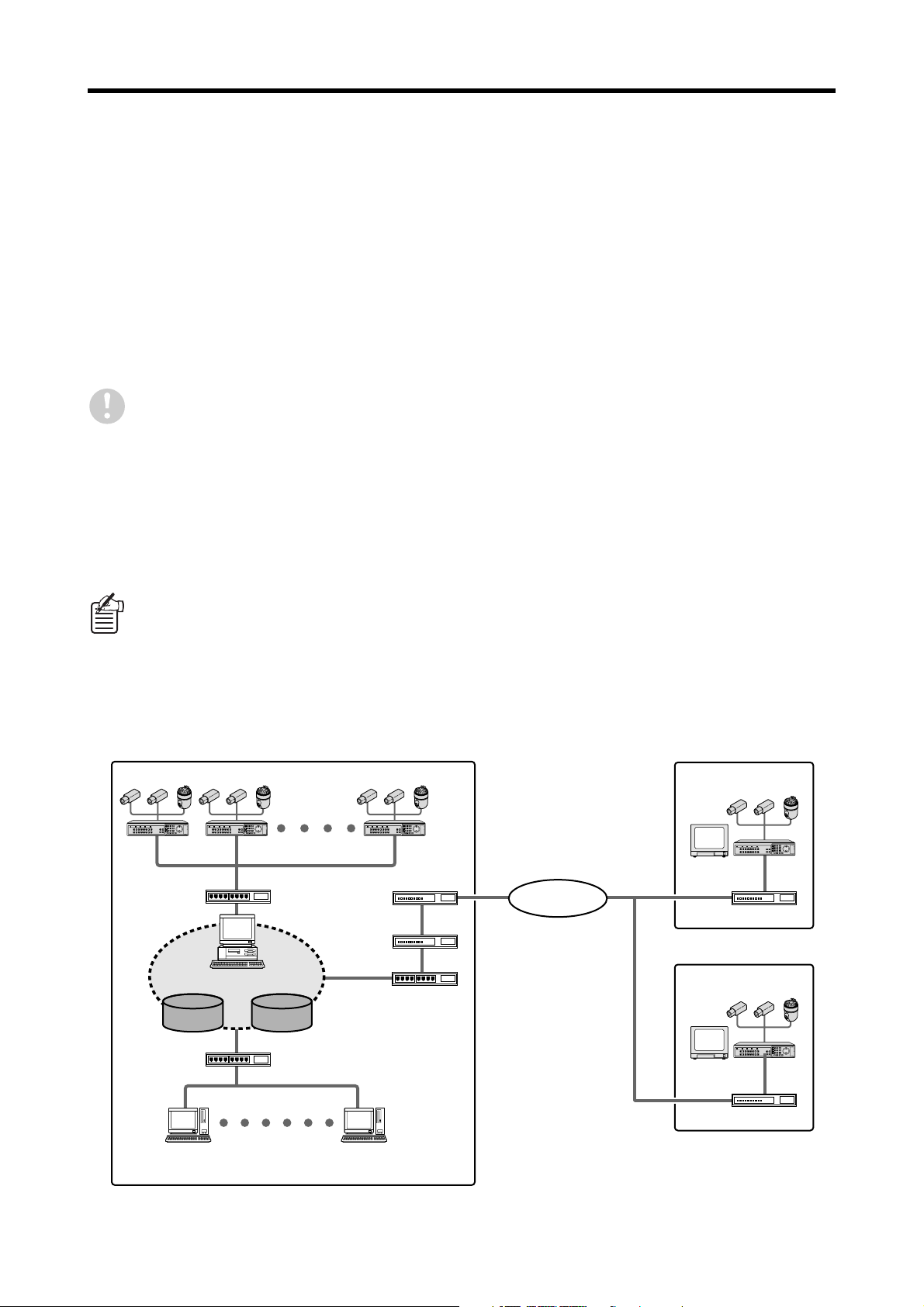
Network connection example
Remote location A
DVR-1 DVR-2 DVR-10
Hub
Master computer
DATA ID/PASS
Router
Firewall
Internet
Remote location B
Hub
DVR-12
Router
DVR-13
Hub
Slave computer (1)
Router
Slave computer (7)
–6– English

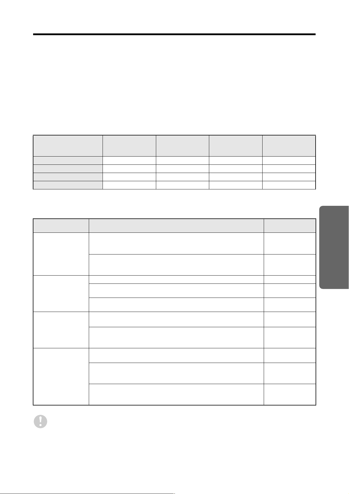
OPERATING ENVIRONMENT
The network operating environment is as follows. The master computer has high loads placed on it because it
acts as the server for the system. Check the required specifications carefully.
Master computer Slave computer
OS
CPU
RAM
VIDEO
MONITOR
HDD
LAN PORT
NET WORK
OTHERS
Windows 2000 Professional (SP4)
Windows XP Professional
Pentium 4 - 3.4 GHz or faster Pentium 4 - 3 GHz
[RECOMENDED: Pentium 4 - 3.4 GHz]
512 MB or more [RECOMENDED: 1024 MB]
XGA (1024 × 768pixel) 16-bit color, DirectX 9.0 or above
[Recommended graphics cards]
ATI RADEON9000 series or later
nVidia GeForce 4 series or later
Quadro 4 series or later
Matrox Millennium P series or later
(On-board video is not recommended.)
XGA (1024 × 768 pixel) 16-bit color
System setup area:120MB System setup area:120MB
Data save area:2GB or above -
100Mbps × 1
[RECOMENDED:1Gbps × 1]
Computer side
LAN: 100Mbps [RECOMENDED:1Gbps]
●
Internet: 1.5Mbps (Downstream) [RECOMENDED: 5Mbps]
●
DVR side
LAN: 10Mbps [RECOMENDED:100Mbps]
●
Internet: 1.5Mbps (Upstream) [RECOMENDED: 5Mbps]
●
CD-ROM Drive (for Software Install)
E-mail account × 1
(SMTP/POP)
100Mbps × 1
-
Even if the above operating environment conditions are satisfied, images may not display correctly if
synchronizing signal distortion occurs.
Windows® is a trademark, or registered trademark of Microsoft Corporation in the United States and/or other countries.
Pentium® is a trademark or registered trademark of Intel Corporation or its subsidiaries in the United States and other
countries.
English – 7 –

SETUP
This section will deal firstly with the procedures for setting up and
running a CCTV monitoring system using the “VA-SW5000” CCTV
system management software. Administrator users should follow the
procedures given here to ensure that all network connections and
initial settings are carried out correctly.
SETUP CONTENTS
BASIC PROCEDURES FOR STARTING UP THE SYSTEM. . . . . P9
REQUIRED SETTINGS FOR NETWORK CONNECTIONS. . . . . P10
SETUP
INSTALLING THE SOFTWARE. . . . . . . . . . . . . . . . . . . . . . . . . . P12
MASTER COMPUTER INITIAL SETTINGS. . . . . . . . . . . . . . . . . P15
SLAVE COMPUTER INITIAL SETTINGS . . . . . . . . . . . . . . . . . . P20
– 8 – English

BASIC PROCEDURES FOR
STARTING UP THE SYSTEM
This section explains the standard procedures for starting up the system. In particular, the Setup section of
this manual is comprised of pages that explain the following procedures, so that you can check the detailed
explanations given on the corresponding pages when carrying out work.
1111
Connecting devices by configuring network settings. (P.10)
Check the operating environment and the device configuration, and connect the DVRs and
computers to the network. Make the following settings beforehand when making network
connections.
Set the IP addresses for the computers.
●●●●
Make the [NETWORK SET] settings for the DVRs.
●●●●
2222
Install this software into the computers. (P.12)
Run the installation CD and follow the instructions that appear on the screen to install the software.
3333
Make the initial settings for the master computer. (P.15)
Run the software at the master computer and follow the instructions that appear on the screen to
make the following initial settings.
Set up the computer as the master computer.
●●●●
(Display language, date format, slave region and IP address settings)
Register a user as the administrator user.
●●●●
Register DVRs.
●●●●
Carry out the operations in [DVR CONNECTION CHECK].
●●●●
Once these initial settings have been completed, it will then be possible to carry out all operations
from the master computer.
4444
Register users. (P.75)
Use [USER MANAGER] in the [SYSTEM MANAGEMENT] menu to register the users that may use
this system. When a user is registered, the user can use their specified [USER ID] and
[PASSWORD] to log into the system from a computer on the network.
5555
Make the settings for the slave computers. (P.20)
Set up the other computers as slave computers.
(Display language, date format, slave region and IP address settings)
6666
Make detailed system settings.
The administrator user can make and change settings that relate to the system operating conditions
and to individual items of registration information in order to create a uniquely customized
management system.
[DVR INFO SETUP] (P.63)
●●●●
[SYSTEM MANAGEMENT] (P.67)
●●●●
[CENTRALIZED SURVEILLANCE SET] (P.107)
●●●●
[DOWNLOAD DATA MANAGER] (P.111)
●●●●
English – 9 –
REQUIRED SETTINGS FOR
NETWORK CONNECTIONS
When using this software over a network connection, you should make the following settings before using the
computers or DVRs.
●●●● Set the IP addresses for the computers.
Set the IP addresses that correspond to the various operating systems for the computers being used.
Double-click [Network and Internet
1
Connections] in [Control Panel].
The [Network and Internet Connections] window will
be displayed.
Click [Local Area Connections].
2
The [Local Area Connections] window will be
displayed, and the settings for the LAN card
(Ethernet adapter) being used will appear in the
[LAN or High-Speed Internet] column.
Right-click on the LAN card
3
(Ethernet adapter) being used, and
then select [Properties (R)] from the
pop-up menu.
The [General] tab window in the [Local Area
Connection Properties] window will be displayed.
Check that [Internet Protocol (TCP/
4
IP)] is selected in the [This
connection uses the following items
(O)] box.
If [Internet Protocol (TCP/IP)] is not selected, select
it.
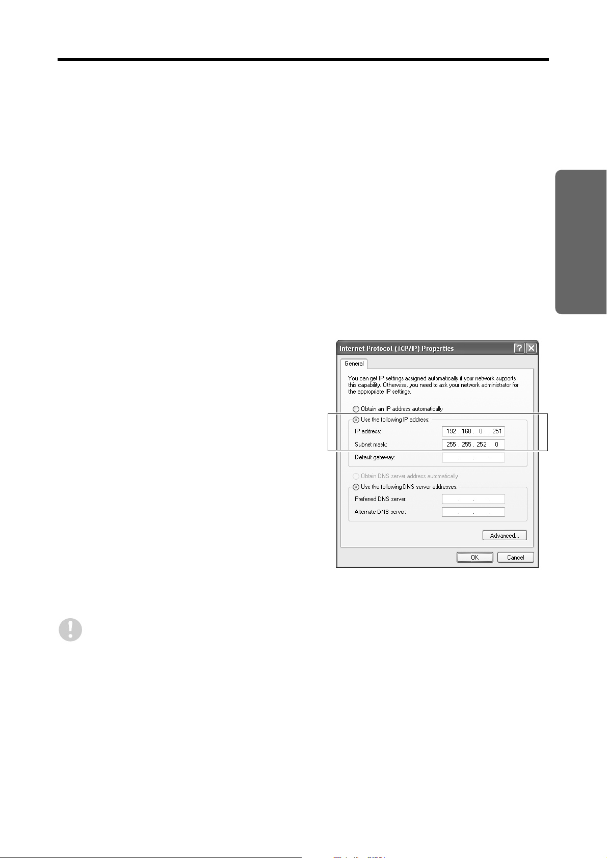
Click [Properties (R)].
5
The [General] tab window in the [Internet Protocol
(TCP/IP) Properties] window will be displayed.
Select [Use the following IP
6
address:] and then type in the IP
address and the subnet mask.
SETUP
If you make the LAN cable connection and IP address settings while the software is already running,
communication problems may occur. If you change these settings after the software has been installed,
exit the software before changing the settings.
– 10 – English
REQUIRED SETTINGS FOR NETWORK CONNECTIONS
●●●● Make the network settings for the DVRs.
Change the following settings in the [NETWORK SET] menu in accordance with the network connection being used.
Refer to the manual for the DVR for details on the setting method.
[NETWORK CONTROL]:
●●●●
Set to “ON (NETWORK)”.
[IP ADDRESS/SUBNET MAK/GATEWAY]:
●●●●
If the DVR is connected via a LAN, set so that the
DVR is in the same segment as the computer.
[PORT]:
●●●●
Normally this setting should be left at “00080”.
[ID/PASSWORD]:
●●●●
The setting method will vary depending on the model
of DVR.
<For the DSR-5009P, DSR-5016 and DSR-5016P>
Make the settings in [USER ID SET].
<For all other models>
Normally the settings should be left at their defaults.
Change the settings only if necessary.
The [IP ADDRESS], [PORT] and [PASSWORD]
setting for ID3 (or the [USER ID] and
[PASSWORD] settings for level 4 in the [USER
ID SET] window) are required when checking
the connection of the DVR, so make a note of
the settings so that you do not forget them.
<NETWORK SET>
NETWORK CONTROL : ON(NETWORK)
NETWORK STATUS : ON
IP ADDRESS : 192.168. 0. 1
SUBNET MASK : 255.255.255. 0
GATEWAY : 0. 0. 0. 0
PORT : 00080
ID : PASSWORD (4-8)
ID1 : 1111--- ID2 : 2222--- ID3 : 3333----
The setting window will vary depending
on the model of DVR.
(The window examples shown are
for the DSR-3700 series.)
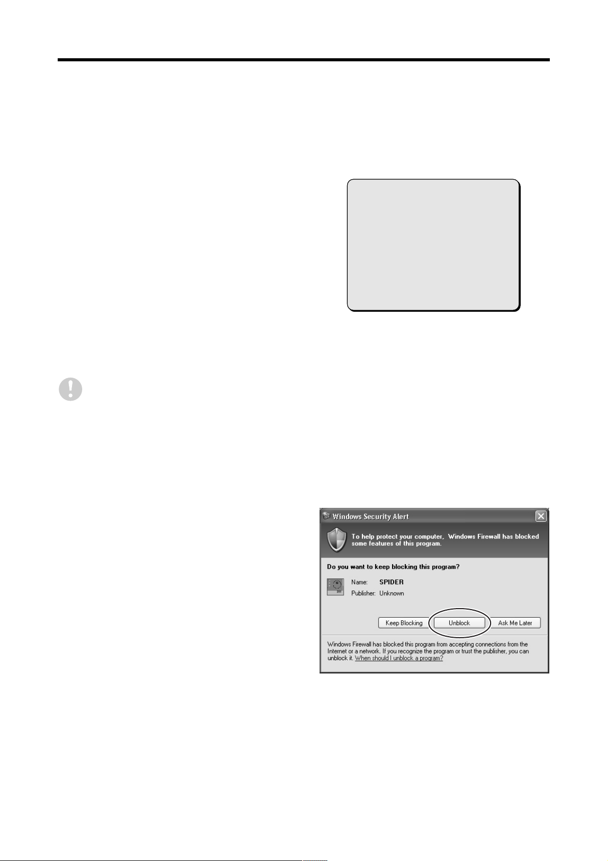
●●●● Disable the firewall function.
If the firewall function of Windows XP or some other
firewall software has been installed and enabled, it may
block communication with the DVR and the system will
not operate correctly. When using this software, be sure
to disable the firewall settings.
Furthermore, Windows XP SP2 is provided with a
standard firewall function. A confirmation window for
checking the firewall settings will be displayed each time
the software is run, so select [Unblock] so that
communication from the DVR will not be blocked.
English – 11 –
INSTALLING THE SOFTWARE
Install the “VA-SW5000” CCTV system management software to the computer that is connected to the
network. It is recommended that you run the installation program and follow he prompts that are displayed on
the screen to install the software.
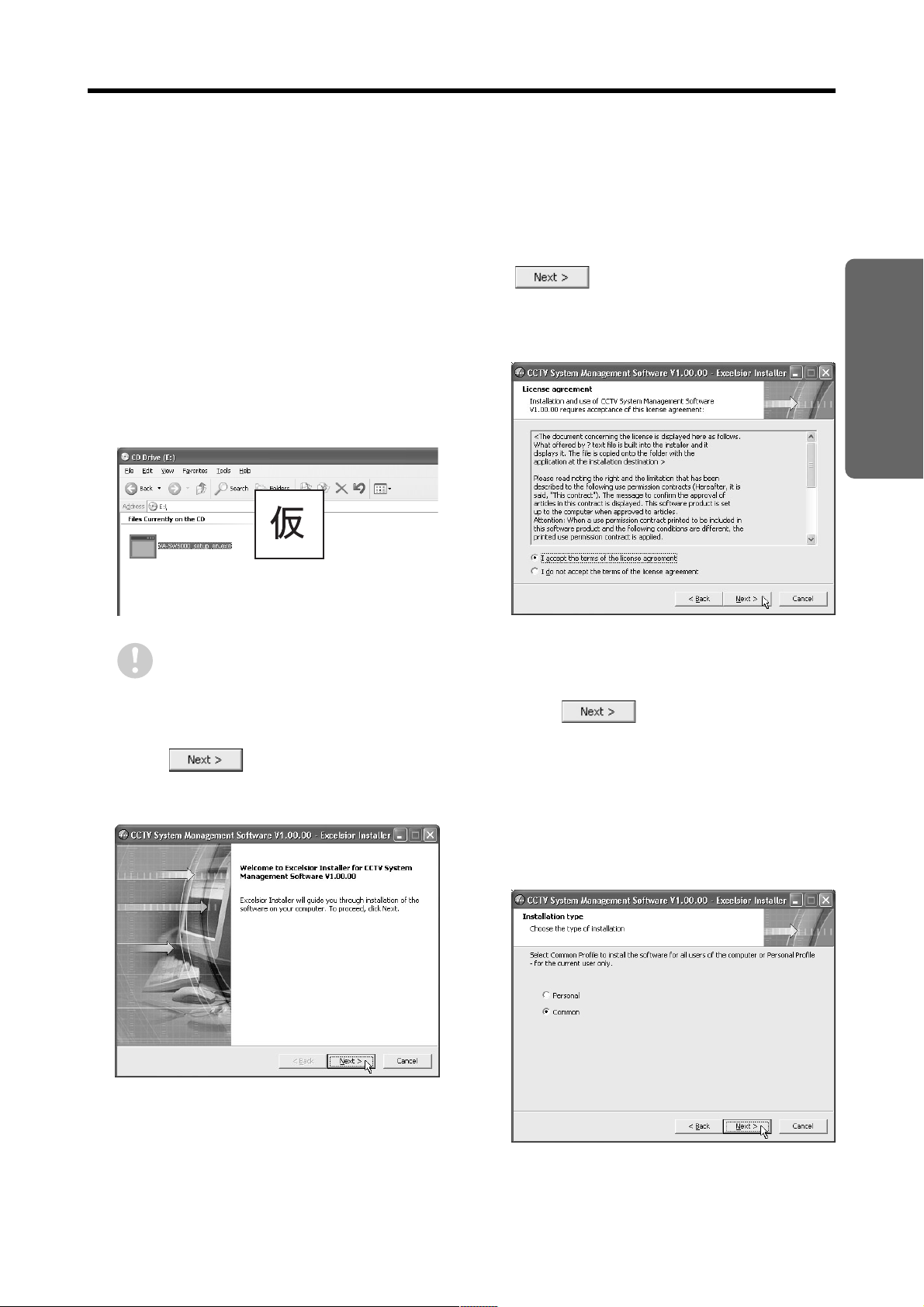
Insert the software installation CD
1
into the CD-ROM drive of the
computer and start the installation
program.
Double-click
2
“VA-SW5000_setup_en.exe”.
Installation will start and the [Welcome] window will
be displayed.
If an older version of the software has
already been installed, the system will not
run correctly. Follow the instructions in
the displayed message to uninstall the
old software. (P.14)
Click in the [Welcome]
3
window.
The [License Agreement] window will be displayed.
Select [I accept…] and click
4
window.
Be sure to check the terms of the License
Agreement carefully.
Select the type of installation in the
5
[Installation type] window and then
click .
[Personal]:
●●●●
The users that can use the software on this
computer will be limited to the user that is
currently installing the software.
[Common] (Default setting):
●●●●
All registered users will be able to use the
software on this computer, with no limits on
users.
in the [License Agreement]
SETUP
– 12 – English
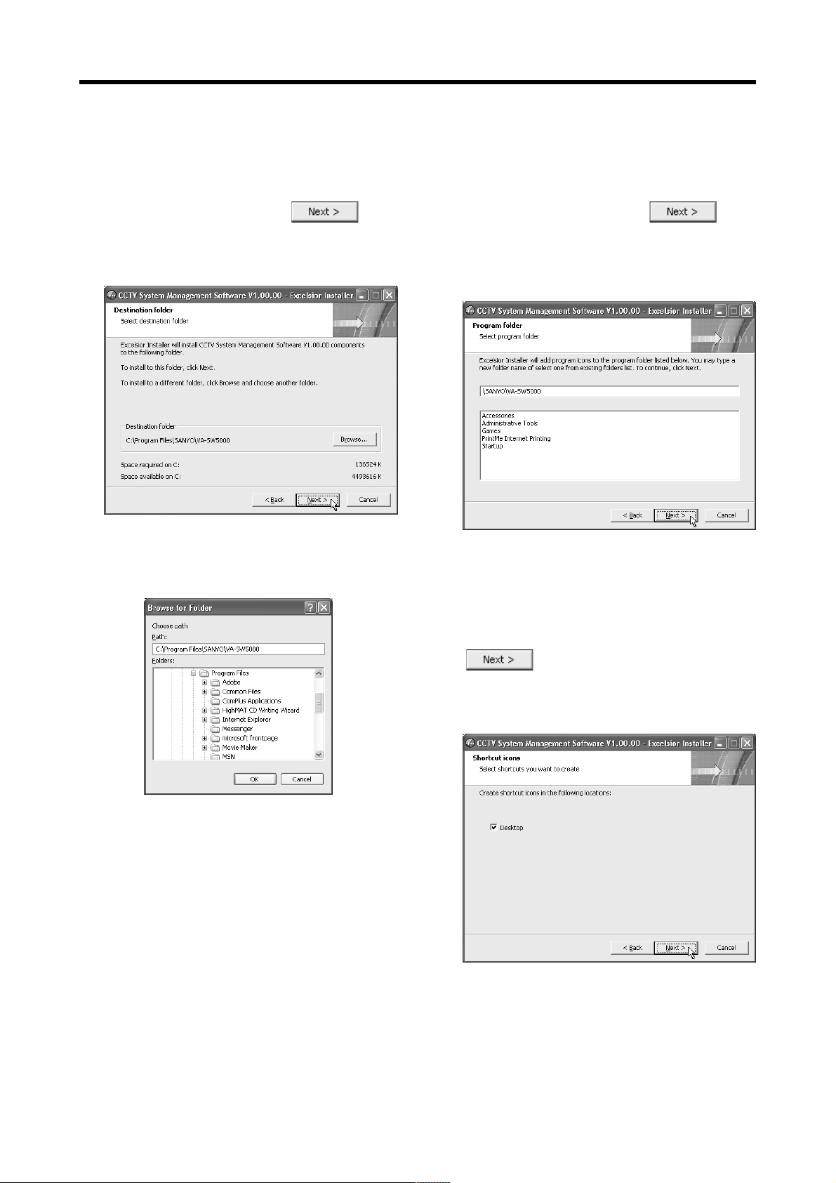
INSTALLING THE SOFTWARE
Specify the folder for installing the
6
software in the [Destination folder]
window and then click .
If there are no particular problems with the default
location, such as with capacity, accept the default
location and then click [Next].
If you would like to change the destination folder for
installing the software to a folder that is different from
the default location, click [Browse…] and select the
folder to be used for the installation.
Select the name of the program
7
folder in the [Program folder]
window and then click .
Normally you should accept the default folder
without changing it. If you would like to change the
program folder, type the folder name into the box, or
select an existing folder from the list underneath.
In the [Shortcut icons] window,
8
select whether or not you would like
a shortcut icon to appear on the
computer's desktop, and then click
.
If you do not want a shortcut icon to appear on the
computer's desktop, unselect the [Desktop] check
box.
English – 13 –
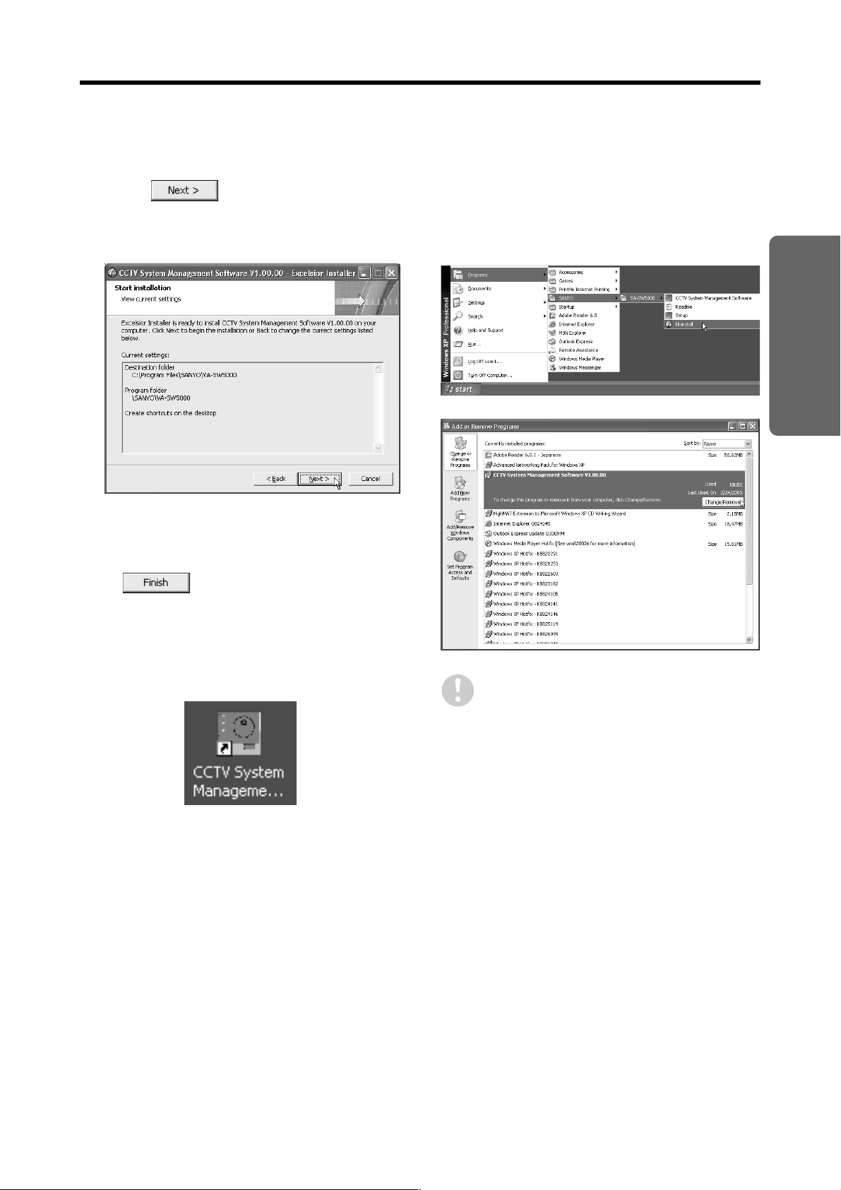
INSTALLING THE SOFTWARE
At the [Start installation] window,
9
click .
Installation of the software will begin, and a progress
bar showing the installation progress will appear in
the [Installing] window.
When the [Installation completed]
10
message is displayed, click
.
Installation will then be complete, and CCTV
System Management Software will appear under
Programs in the Start menu. If you selected a
shortcut icon to be created in step 8, a shortcut
icon for the software will also appear on the
desktop.
<Uninstalling the software>
To uninstall (delete) this software, select [Start]
[Programs] → [SANYO] → [VA-SW5000] → [Uninstall],
or double-click [Add or Remove Programs] in the Control
Panel, select [CCTV System Management Software] and
then uninstall it.
SETUP
Some files that were created previously may
still remain even after the software has been
uninstalled. If this is the case, delete the
installation folder (default setting: C:\program
Files\SANYO\VA-SW5000).
– 14 – English
MASTER COMPUTER INITIAL
SETTINGS
After the software has been installed, you then need to make some initial settings the first time the software is
run. If the system has been newly created, you will first need to specify a single computer as the master
computer, and then make the default settings in “Master Computer Setup” and “Registering DVRs and
Checking Connections”.
bbbbSet up the computer as the master computer
When the software is run for the first time, the “SetUp” application software will be run at the same time and the windows
containing the initial settings that need to be made will be displayed in sequence. Follow the instructions that appear on
the screen to carry out the setup.
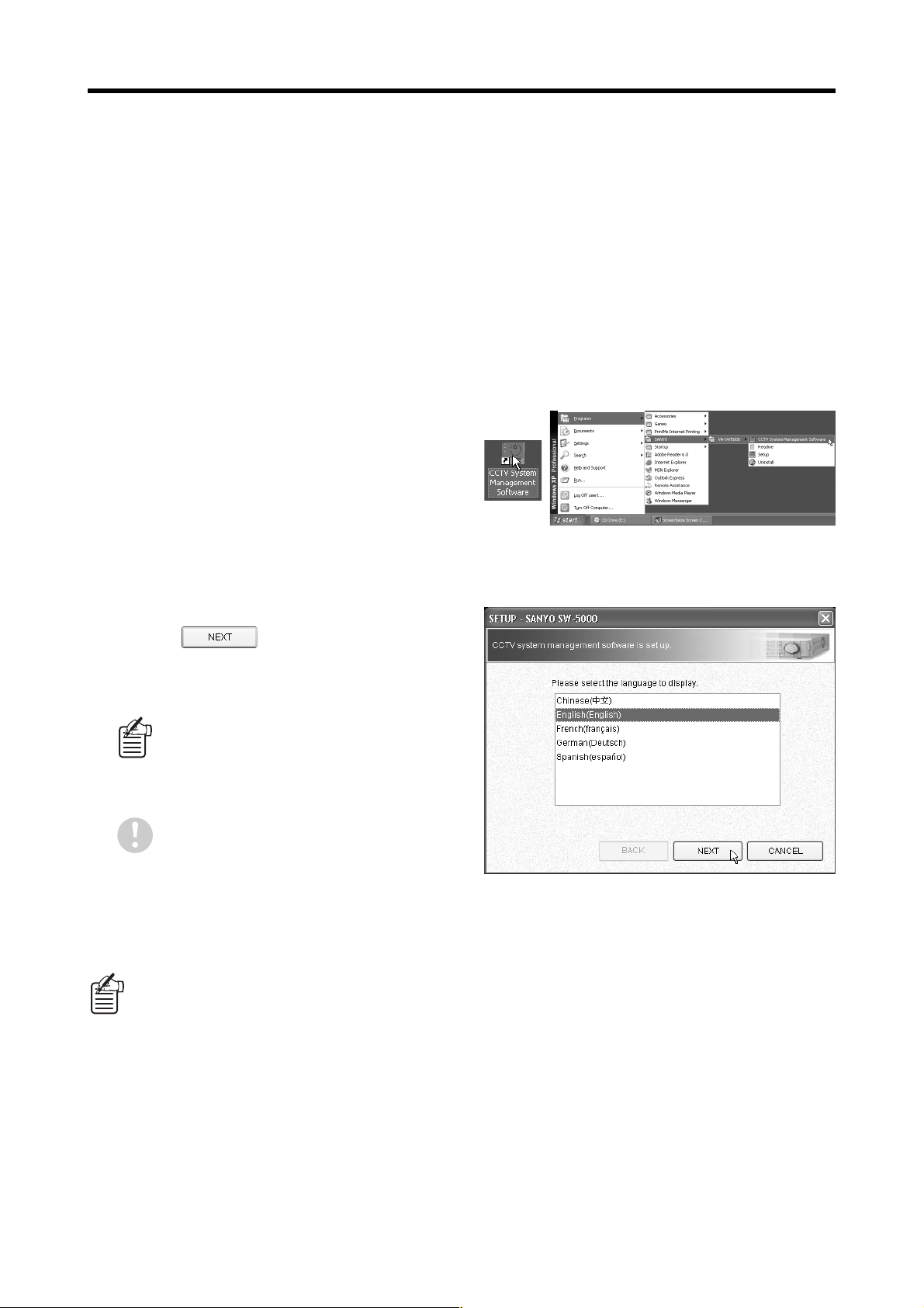
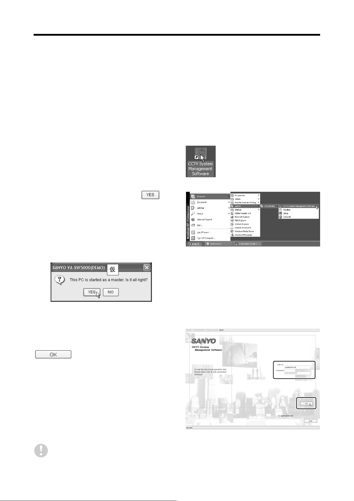
Start the software.
1
Double-click the shortcut icon on the Desktop, or
select [Programs] → [SANYO] → [VA-SW5000] →
[CCTV System Management Software] from the
Start menu to run the software and display the setup
screen.
Select the display language.
2
Select the display language for the software and
then click .
Displayed languages:
Chinese, English, French, German, Spanish
The display language and the date format
in the next window can be changed later
using [LANGUAGE/DATE FORMAT SET]
in the [SYSTEM MANAGEMENT] menu.
(P.87)
The appropriate fonts for a selected
language must be installed into the
computer, otherwise that language will
not be displayed correctly.
If you click [CANCEL] in any of the windows while carrying out setup, the setup application software
●●●●
will close and the display will return to the computer’s desktop. You can repeat the setup operations
from the beginning again when the software is restarted.
Even after all of the setup operations at the master computer have been completed, you can run the
●●●●
“SetUp” application independently from the computer’s Start menu to redo the setup at any time. If you
run the “SetUp” application while the software is already running, any changes that you make will be
applied the next time the software is started up.
If the computer is running Windows XP SP2 as its operating system, a confirmation window for
●●●●
checking the firewall settings will be displayed the first time the software is run, so select [Unblock] to
disable the firewall so that communication from the DVR will not be blocked. (P.11)
English – 15 –
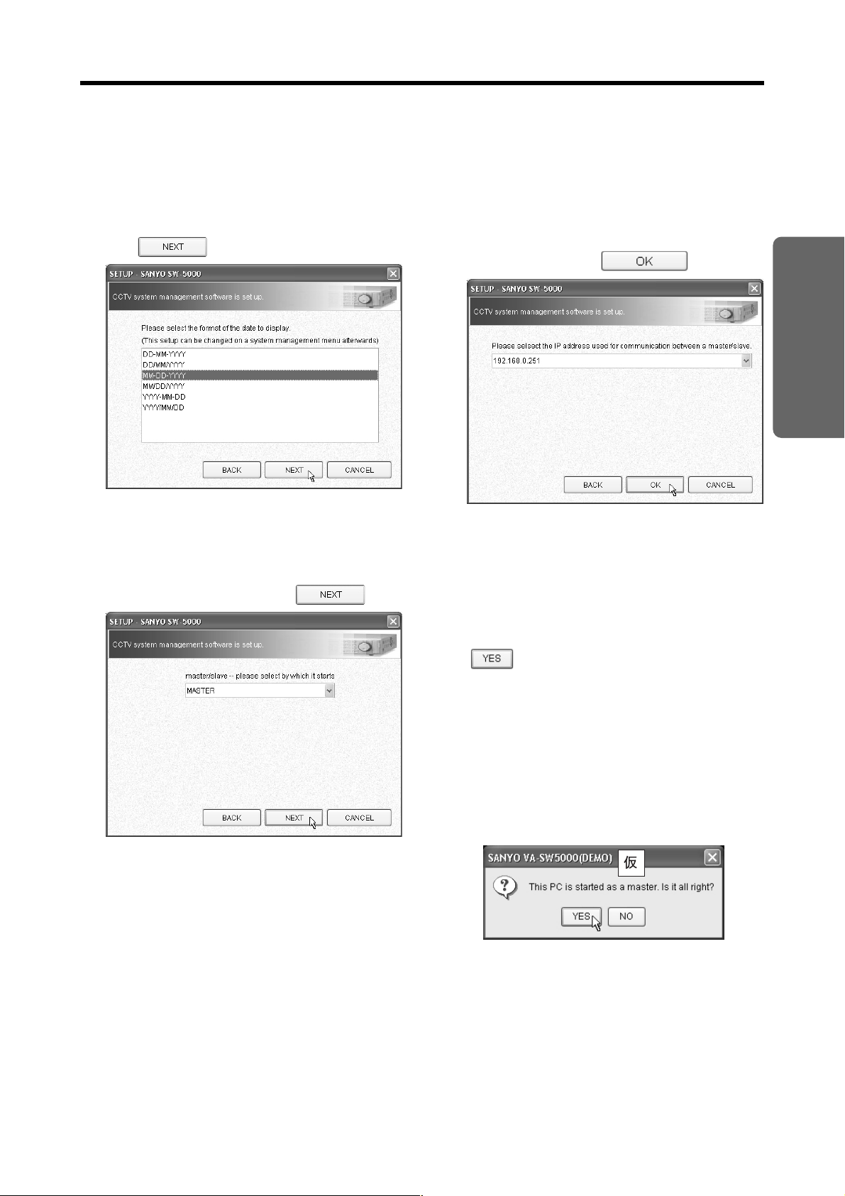
MASTER COMPUTER INITIAL SETTINGS
Select the date format.
3
Set the display format or the date within the
software.
Select from one of the six display patterns and then
click .
Select the startup designation
4
([MASTER]/[SLAVE]) for the
software.
Select “MASTER” and then click .
Select the IP address for connecting
5
to the network.
The IP addresses for all of the computer's LAN ports
will be displayed. Select the IP address to be used
for connecting to the slave computers across the
network and then click .
Master computer startup
6
confirmation
A startup confirmation dialog box will be displayed.
This dialog box will always be displayed when the
software is started up on the master computer,
regardless of initial settings. You should always click
SETUP
unless you want to do something such as
change which computer is to be the master
computer.
[YES]:
●●●●
The computer will then restart as the master
computer, and the administrator user registration
dialog box will then be displayed.
[NO]:
●●●●
The startup will be halted and the software will
close.
– 16 – English
MASTER COMPUTER INITIAL SETTINGS
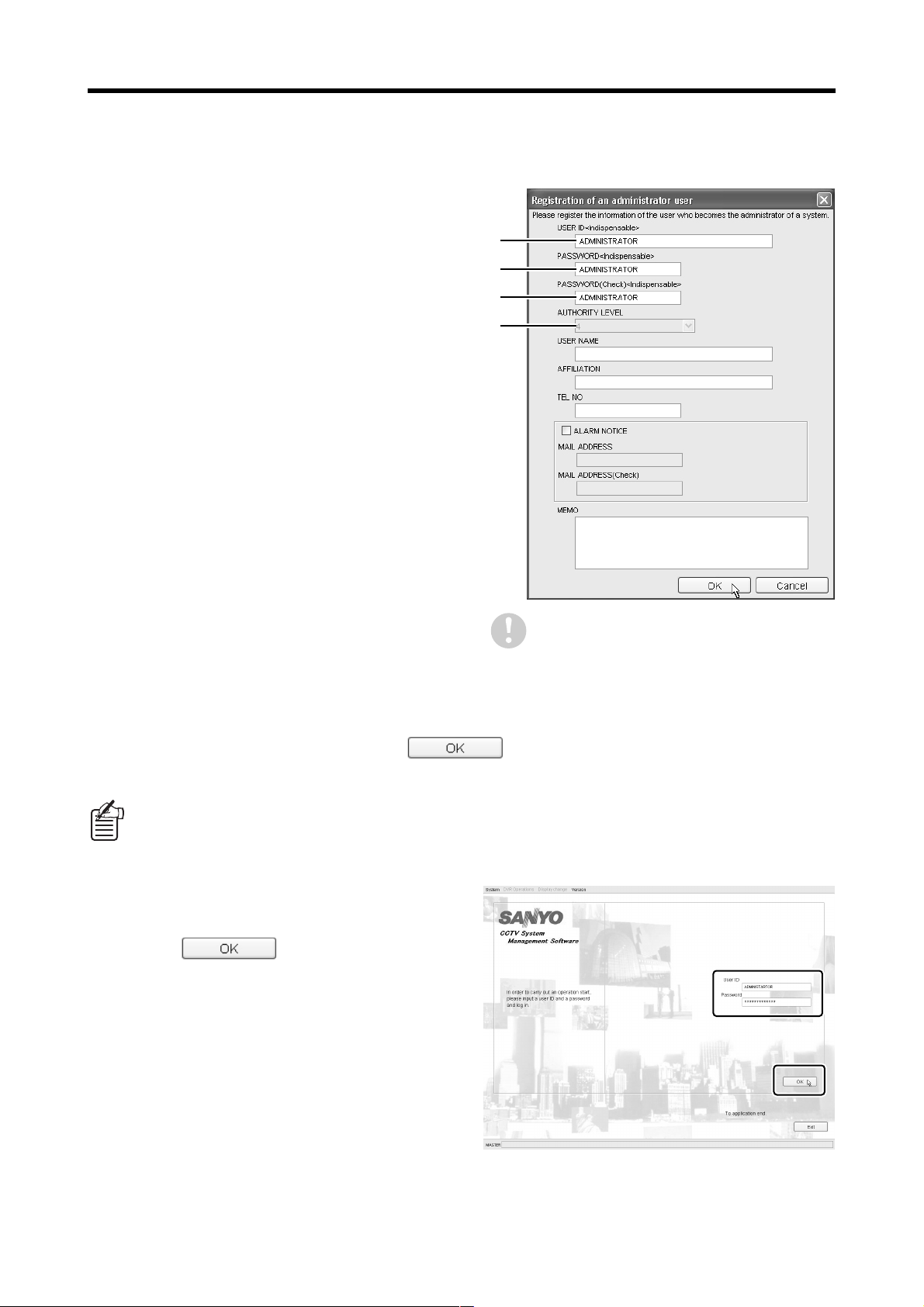
Register the administrator user
7
information
Next, enter the required information for the
administrator user in the [Registration of an
administrator user] dialog box.
You can use [USER MANAGER] in the [SYSTEM
MANAGEMENT] menu to add and change user
registration information, but you are required to enter
something for [USER ID] and [PASSWORD] when
making the initial settings. Refer to [USER
MANAGER] in the [SYSTEM MANAGEMENT] menu
for details. (P.75)
[USER ID]
1
Enter the ID to use for identifying the user. This
ID cannot be changed later.
It can consist of a combination of up to 16
single-byte alphanumeric characters. It may not
consist of only numerals.
[PASSWORD]
2
In the [PASSWORD] box, enter the password for
user authentication when the software is started.
Up to 16 single-byte alphanumeric characters can
be entered.
[PASSWORD (Check)]
3
This checks the password. Re-enter the same
password that you entered in step
[AUTHORITY LEVEL]
4
The user level for the administrator user will be
automatically set to “4”.
....
1
2
3
4
This dialog box will be displayed each time
2
.
the software is restarted, until the
administrator user registration has been
completed.
After entering all the required information, click to end the setup. You will then be able to log in to the
system using the master computer.
The information that has been registered for the master computer during setup is automatically registered
in [PC MANAGER] in the [SYSTEM MANAGEMENT] menu.
Log in.
8
The login window will be displayed. Enter the [User
ID] and [Password] that were registered earlier and
then click .
English – 17 –
MASTER COMPUTER INITIAL SETTINGS
bbbbRegister DVRs and check their connections
The setup for the master computer will be complete and you can now log in to the system, but in order to actually view
images, you must now register DVRs and check their connections. These operations can be carried out at any time, but it
is recommended that you carry them out all at once when the software is started up for the first time.
The following section explains the basic procedure for registering DVRs and checking their connections. Refer to [DVR
MANAGER] in the [SYSTEM MANAGEMENT] menu for details. (P.80)
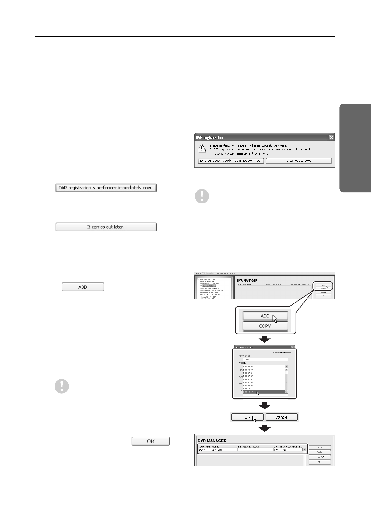
Select the DVR registration
1
procedure.
No DVRs are registered in the system yet while the
initial settings are being made, so this dialog box is
displayed to ask you how you would like to register
the DVRs.
Select [DVR registration is performed immediately
now.] and proceed to the explanation.
●●●●
The procedure will jump to the [DVR MANAGER]
window. Following the instructions in the [INFO]
dialog box to register DVRs and check their
connections.
●●●●
The dialog box will close and the display will
switch to the monitoring window, but nothing will
be displayed in the window because no DVRs
have been registered yet.
This dialog box will be displayed each time
the software is restarted, until DVR
registration has been completed.
SETUP
Register DVRs.
2
Click in the [DVR MANAGER]
window to display the [DVR INFO SETUP] dialog
box, and then enter the required information for the
DVR. The required details that must be entered to
register a DVR are [DVR NAME] and [MODEL].
(P.81)
[DVR NAME]:
●●●●
These will appear in all menus and monitoring
windows as the name of the DVR for system
administration.
It can consist of up to 16 single-byte
alphanumeric characters.
An error message will be displayed
●●●●
if the [DVR NAME] already exists.
The [DVR NAME] that is registered
●●●●
cannot be changed later.
[MODEL]:
●●●●
Select the DVR model from the list box.
After entering the details, click .
The DVR will be registered and the registration
information will be displayed in the [DVR
MANAGER] list.
– 18 – English
MASTER COMPUTER INITIAL SETTINGS
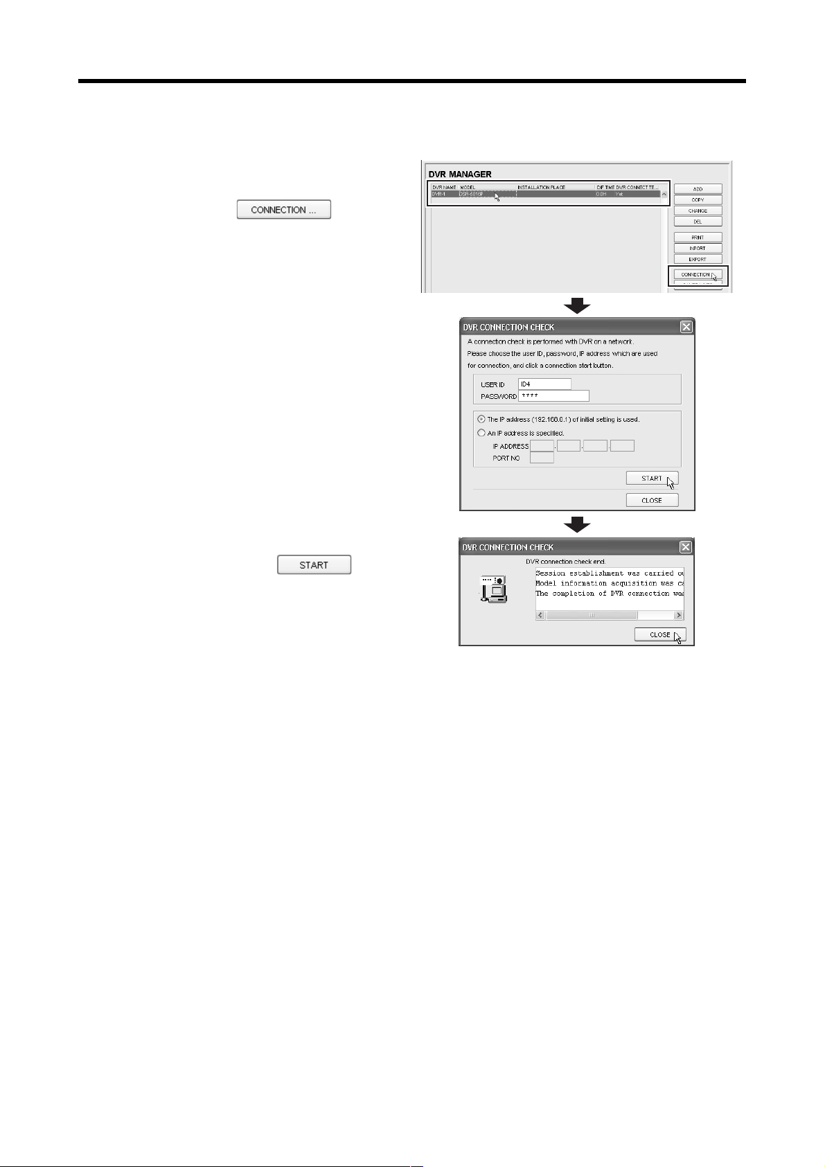
Check the DVR connection.
3
Click the DVR name in the [DVR MANAGER] list to
select it, and then click .
The [DVR CONNECTION CHECK] dialog box will be
displayed. Enter the following setting values for the
DVR. (P.82)
[USER ID]
●●●●
[PASSWORD]
●●●●
[IP ADDRESS]
●●●●
[PORT]
●●●●
aaaaEnter the user ID and password
The method of entering these will vary as follows
depending on the model of DVR.
<For the DSR-5009P, DSR-5016 and DSR-5016P>
Enter the user ID and password that were registered
for level 4 at the DVR using [USER ID SET].
<For all other models>
The user ID will be fixed at “ID3”. (It cannot be
re-entered.) Enter the password that was registered
for user level 3 at the DVR using [NETWORK SET].
After entering the details, click .
Connection to the DVR will start, and if the
connection is completed normally, the message
“DVR connection check end.” will be displayed.
This connection operation will result in the creation
of a menu file (DVR setting information) on the
computer that contains the DVR management
information, and it will then be possible to monitor
images from that DVR and to change the DVR's management information.
Register all DVRs.
4
Repeat the operations in steps 2 and 3 to register and check the connections for all DVRs that are to be used.
* This completes the initial settings, and the single administrator user can now freely access all DVRs from the master
computer. After this, you can set up additional registrations for users to carry out monitoring operations and connect
additional computers to the system as required.
To register a user:
●●●●
Use [USER MANAGER] in the [SYSTEM MANAGEMENT] menu to register additional users that may use this system.
User registration will set a [USER ID] and [PASSWORD] that users must use to log in to the system. (P.75)
To add more computers:
●●●●
Set up the other computers as slave computers. (See next page.)
English – 19 –
SLAVE COMPUTER INITIAL
SETTINGS
If more than one computer is connected to the system, make the initial settings for the master computer first,
and then make the initial settings for the slave computers. In the same way as for the master computer, the
settings windows will be displayed in sequence when the software is started up, so follow the on-screen
instructions to complete the settings.
Steps 1 to 3 are the same as the corresponding master computer setup procedures. (P.15)
Start the software.
1
Select the display language.
2
Select the date format.
3
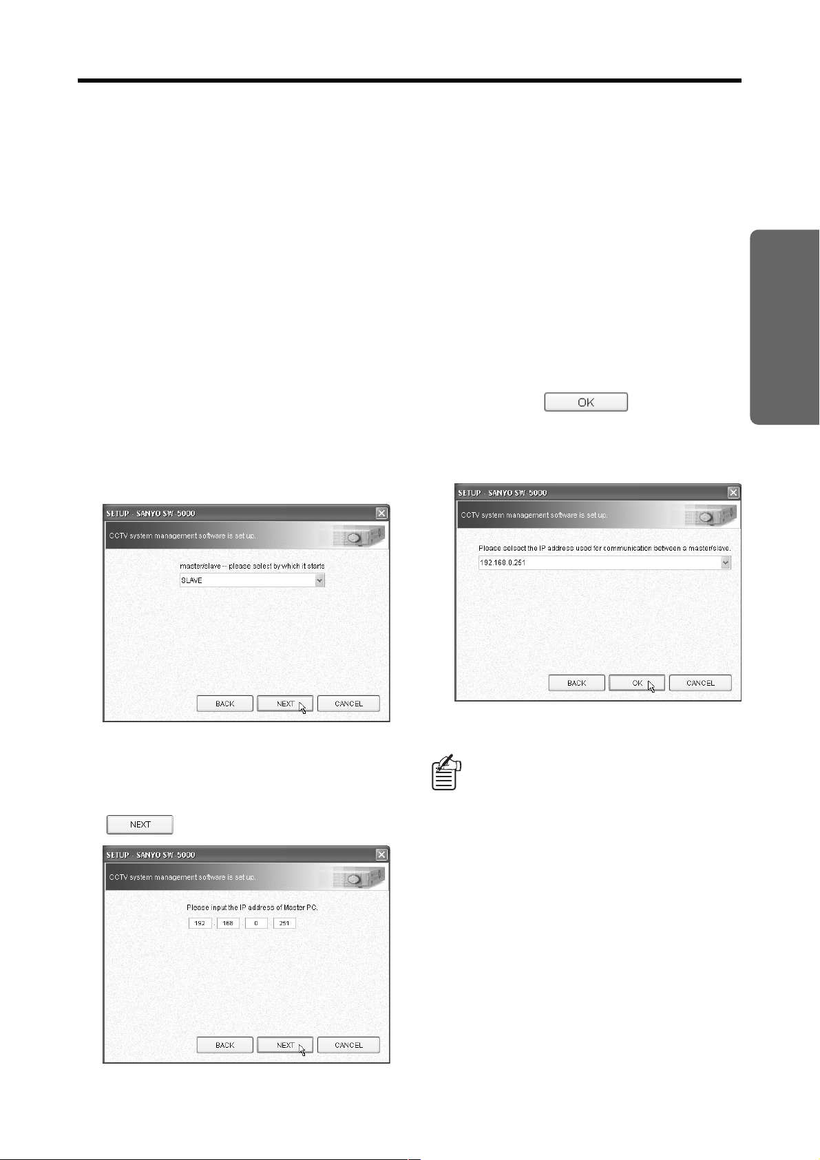
Select the startup designation
4
([MASTER]/[SLAVE]) for the
software.
Select “SLAVE” and then click [NEXT].
Select the IP address for connecting
6
to the network.
The IP addresses for all of the computer's LAN ports
will be displayed. Select the IP address to be used
for connecting to the master computer across the
network.
When you click , the setup will be
complete and the display will switch back to the login
window.
To log in, enter the [USER ID] and [PASSWORD]
that have been set for the administrator user. (P.76)
SETUP
Enter the IP address for the master
5
computer.
Enter the IP address that was registered in the initial
settings for the master computer and then click
.
The information that has been registered
●●●●
for the slave computer during setup is
automatically registered in [PC
MANAGER] in the [SYSTEM
MANAGEMENT] menu.
Up to 98 slave computers can be
●●●●
registered, and up to seven can be
connected to the system at the same time.
If the computer is running Windows XP
●●●●
SP2 as its operating system, a
confirmation window for checking the
firewall settings will be displayed the first
time the software is run, so select
[Unblock] to disable the firewall so that
communication from the DVR will not be
blocked. (P.11)
– 20 – English

MEMO
. . . . . . . . . . . . . . . . . . . . . . . . . . . . . . . . . . . . . . . . . . . . . . . .
. . . . . . . . . . . . . . . . . . . . . . . . . . . . . . . . . . . . . . . . . . . . . . . .
. . . . . . . . . . . . . . . . . . . . . . . . . . . . . . . . . . . . . . . . . . . . . . . .
. . . . . . . . . . . . . . . . . . . . . . . . . . . . . . . . . . . . . . . . . . . . . . . .
. . . . . . . . . . . . . . . . . . . . . . . . . . . . . . . . . . . . . . . . . . . . . . . .
. . . . . . . . . . . . . . . . . . . . . . . . . . . . . . . . . . . . . . . . . . . . . . . .
. . . . . . . . . . . . . . . . . . . . . . . . . . . . . . . . . . . . . . . . . . . . . . . .
. . . . . . . . . . . . . . . . . . . . . . . . . . . . . . . . . . . . . . . . . . . . . . . .
. . . . . . . . . . . . . . . . . . . . . . . . . . . . . . . . . . . . . . . . . . . . . . . .
. . . . . . . . . . . . . . . . . . . . . . . . . . . . . . . . . . . . . . . . . . . . . . . .
. . . . . . . . . . . . . . . . . . . . . . . . . . . . . . . . . . . . . . . . . . . . . . . .
. . . . . . . . . . . . . . . . . . . . . . . . . . . . . . . . . . . . . . . . . . . . . . . .
. . . . . . . . . . . . . . . . . . . . . . . . . . . . . . . . . . . . . . . . . . . . . . . .
English – 21 –

OPERATION
This section explains the normal screen operating methods, and is
mainly directed toward the general user. Use this section to become
fully familiar with the required operating methods for carrying out
monitoring tasks, including monitoring, recording and playback, and
other available functions also. The on-screen operations that can be
carried out will be limited by the user level that has been set for the
user.
OPERATION CONTENTS
DISPLAY WINDOW CONFIGURATION. . . . . . . . . . . . . . . . . . . . P23
USER LEVELS AND OPERATION MENUS . . . . . . . . . . . . . . . . P24
STARTING UP/CLOSING AND LOGGING IN AND OUT . . . . . . P25
MONITORING WINDOW LAYOUT. . . . . . . . . . . . . . . . . . . . . . . . P27
DISPLAY SCREEN PATTERNS. . . . . . . . . . . . . . . . . . . . . . . . . . P32
MONITORING LIVE IMAGES. . . . . . . . . . . . . . . . . . . . . . . . . . . . P35
USING THE [CENTRALIZED SURVEILLANCE] FUNCTION . . . P36
PLAYING BACK RECORDED IMAGES . . . . . . . . . . . . . . . . . . . P38
RECORDING MONITORED IMAGES . . . . . . . . . . . . . . . . . . . . . P40
USING THE CAMERA CONTROL FUNCTIONS . . . . . . . . . . . . . P43
SEARCHING FOR RECORDED IMAGES . . . . . . . . . . . . . . . . . . P45
DOWNLOADING RECORDED IMAGES . . . . . . . . . . . . . . . . . . . P59
COPYING RECORDED DATA TO THE ARCHIVE AREA. . . . . . P61
OPERATION
– 22 – English
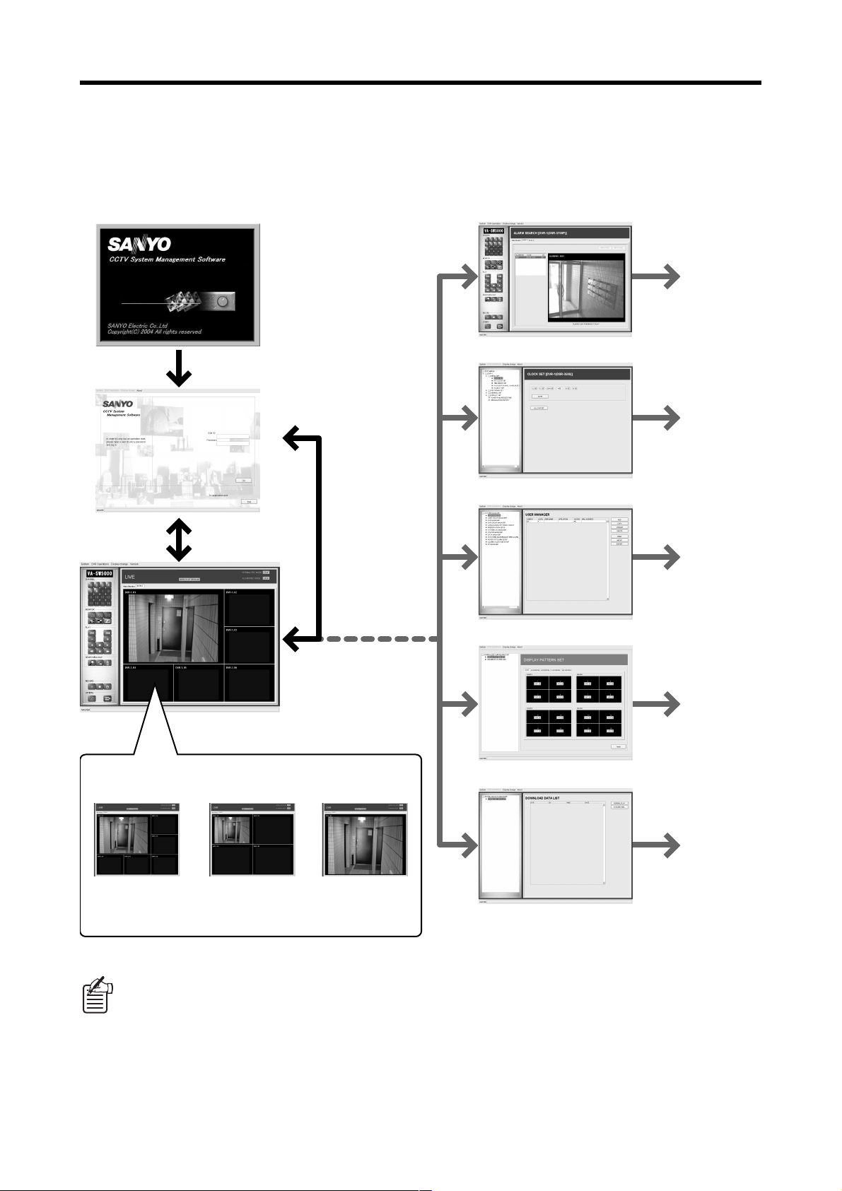
DISPLAY WINDOW CONFIGURATION
When the software is started up, the login window first appears, and then the monitoring window is displayed.
This system is comprised of several different types of window for carrying out searches and management
operations in addition to the monitoring window, and you can switch the window to whichever window is
required.
(P.45)
Startup window
Login window
(P.25)
SURVEILLANCE window
(P.27)
Search window
(P.57)
DVR INFO SETUP window
(P.61)
SYSTEM MANAGEMENT window
(P.93)
Display window patterns (P.32)
1 Multi screen 2 Quad screen 3 Single screen
(6/9/13/
16-screen
multi screen)
The windows that can be displayed will be limited by the user level that has been set for the user.
●●●●
Each main menu window has a hierarchical structure consisting of sub-menus and their related dialog
●●●●
boxes.
If you select [System] →→→→ [MINIMIZE] on the menu bar, the window will be minimized and store on the
●●●●
taskbar.
This software puts a high processing load on the computer, so it is recommended that you do not run
other applications at the same time.
English – 23 –
CENTRALIZED SURVEILLANCE SET window
(P.97)
DOWNLOAD DATA MANAGER window
USER LEVELS AND OPERATION
MENUS
The user levels for all users who operate the computers can be set to one of four levels. The user level is
verified by means of the password that is entered when the user logs in, and the operation menus that the
user can use are limited depending on the user level.
The user IDs and passwords are set by the administrator user using [USER MANAGER] in the [SYSTEM
MANAGEMENT] menu. (P.76)
●●●● Comparison of user levels
System
Monitoring
User level
1 (Monitoring user)
2 (Playback user)
3 (Recording user)
4 (Administrator user)
1
operations
F ×××
FF××
FFF×
FFFF
●●●● Operation menus for each user level
Playback
2
operations
Recording
3
operations
m: Operations allowed ×: Operations not allowed
4
management
operations
Type of operation Operation menu
Monitoring
1
operations
Playback
2
operations
Recording
3
operations
System
4
management
operations
Operations connected to monitoring live images, such as setting DVR
●
channels and switching window layouts
Registering channels in [Centralized Surveillance]
●
Display language and date format selection
●
Viewing of the [STATUS MANAGER] window
●
Playback operations for recorded images Monitoring window
●
Searching through recorded images and viewing and playback of
●
searched images
Saving operations for recorded images, such downloading and
●
copying to archive area
Normal recording using manual operations
●
“ON/OFF” setting for timer recording operations
●
Viewing download information and playback of downloaded images [DOWNLOAD
●
[DVR INFO SETUP] (Setting DVR operating conditions) [DVR INFO
●
Setting and viewing management information for running the system,
●
such as DVR information and user information
Setting display pattern for [Centralized Surveillance] [CENTRALIZED
●
Operation
window
Monitoring window
[SYSTEM
MANAGEMENT]
window
Search window
Monitoring window
Monitoring window
DATA MANAGER]
window
SETUP] window
[SYSTEM
MANAGEMENT]
window
SURVEILLANCE
SET] window
OPERATION
Up to a maximum of 64 users can be registered. More than one user can be set for each user level, but the
same user or administrator user cannot be logged in more than once at the same time.
– 24 – English
STARTING UP/CLOSING AND
LOGGING IN AND OUT
For normal operation, make the following settings beforehand so that the various users can start up the
software and log into the system.
Install the software into the computer and make the specified initial settings.
●●●●
The administrator user should set the user level, [USER ID] and [PASSWORD] for each user that uses the
●●●●
system.
bbbbStarting up the software
Either of the following methods can be used to start up the software.
Double-click the shortcut icon on the computer
1
desktop.
Alternatively, select “CCTV System Management
2
Software” from [Programs] in the Start menu.
<Starting up at the master computer>
When the software is started up at the master
computer, the startup confirmation dialog box will be
displayed at first. You should always click
unless you want to do something such as change
which computer is to be the master computer.
[YES]:
●●●●
The computer will be started up as the master
computer.
[NO]:
●●●●
The startup will be halted and the software will
close.
1
2
If the software is running normally, the login window will be displayed and registered users can then log in.
bbbbLog in
When logging into the system after the software has
started up, enter the [User ID] and [Password] for the
registered user into the login window and then click
. If the [User ID] and [Password] are
entered correctly, the display will then switch to the
monitoring window.
If the [Password] is entered incorrectly, an error message
will be displayed, so re-enter the password.
If the [User ID] matches the user ID of a user that has already logged into the system, an error message
●●●●
will be displayed.
Only one administrator user may be logged into the system at any one time.
●●●●
English – 25 –

STARTING UP/CLOSING AND LOGGING IN AND OUT
bbbbLogging out
To log out of the system, select [LOGOUT] from the
[System] pull-down menu. The window that is currently
being displayed will close and the display will return to
the login window.
The next time the same user logs in, the same
connections and display status that the user
was using immediately before they logged
out last time will be restored.
bbbbExiting the software
To exit the software, click at the bottom of the login window.
To exit the software after logging into the system, first log out of the system to return to the login window and then exit the
software.
If a problem such as a frozen screen occurs, do not forcibly exit the software by any means other than that
described above. If you forcibly exit the software, unexpected problems may occur. Always be sure to
return to the login window before exiting the software.
OPERATION
– 26 – English
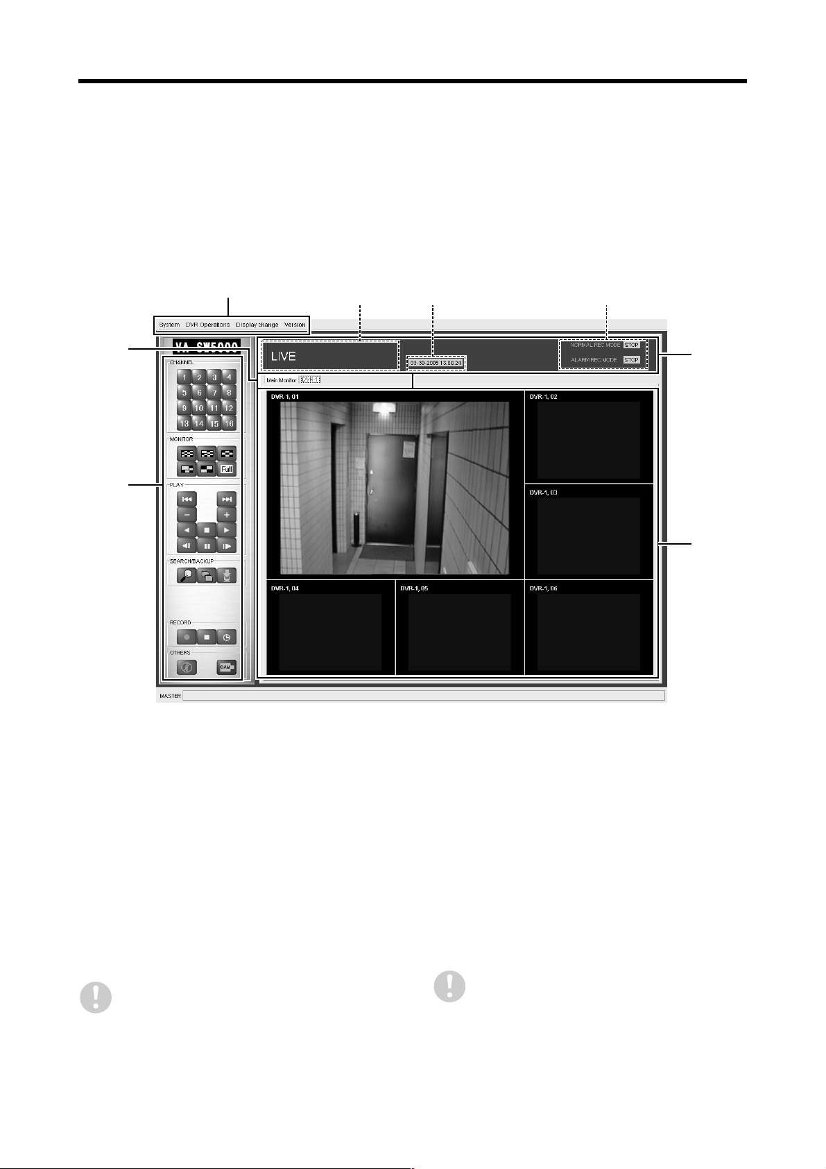
MONITORING WINDOW LAYOUT
After you log into the system using the software, the first window that is displayed is the monitoring window. In
addition to monitoring images, this window is used for basic monitoring user-level operations such as
recording and playback. In addition, this window can be used as a starting point for switching to other
operation and setting windows.
bbbbWindow structure and functions of each window component
4
3
2
21
3
1
5
(The example shows a 6-screen multi screen.)
Operating mode display
1
This shows the operating status and clock time for the DVRs.
Image mode:
1
This shows the image mode for the images that
are currently being displayed.
[LIVE]: Live images
●●●●
[PLAY]: Playback images
●●●●
Time:
2
This shows the time at the DVR in accordance
with the image mode.
In live mode: Current date and time
●●●●
In playback mode: Recording date and time
●●●●
The date display format can be changed using
the [DATE FORMAT] setting.
English – 27 –
Recording/playback mode:
3
This shows the operating status for recording or
playback.
Recording:
●●●●
The DVR recording status for each recording
mode is displayed at all times. (P.40)
Playback:
●●●●
During playback operation, the recording area
and playback speed (playback mode) for the
playback images are displayed. (P.38)
This DVR information is not displayed during
[Centralized Surveillance] display.
MONITORING WINDOW LAYOUT
Menu bar (P.29)
2
This lets you specify various software commands.
When you click on a menu in the menu bar, a pulldown menu is displayed. Click on a specific
command in the menu to select it.
Control panel (P.30)
3
Buttons corresponding to commands that are used
most frequently are arranged on the control panel.
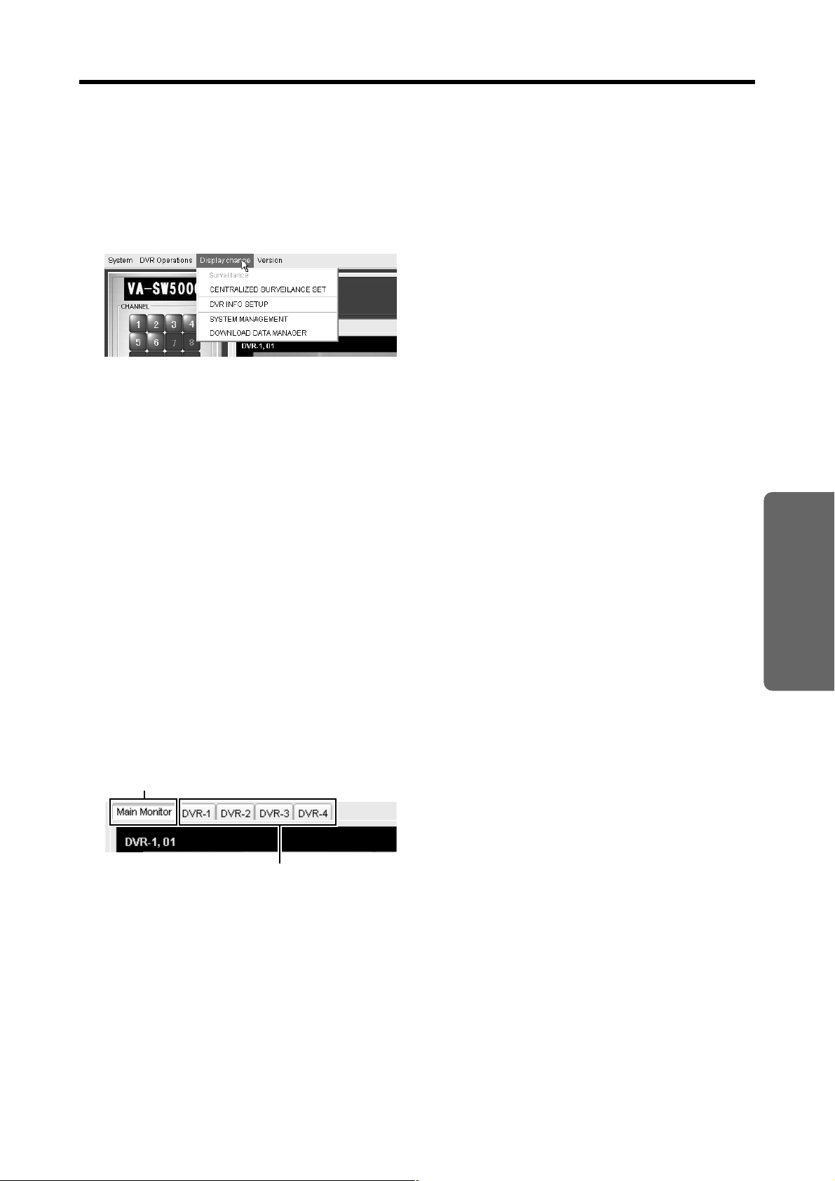
DVR tags (P.31)
4
This displays the DVRs that are currently connected
in the form of tags. Operations such as live image
monitoring and image recording and playback can
be carried out for the DVRs that are displayed as
tags.
When you click on a tag to select it, the display
●
switches to images from that DVR.
When a new tag is created, the initial display
●
becomes a multi screen display, but the display
pattern can be freely switched.
The DVR that is currently selected (for which
●
images are currently being displayed) is indicated
by an orange line marking the top of the tag.
The [Main Monitor] tag at the left side of the
●
window is always displayed to enable you to
switch to [Centralized Surveillance]. (P.36)
Image display area
5
Live images and playback images are displayed
here.
Normally this displays images from a single DVR.
●
You can use the control panel or the menu bar to
switch to 4-screen and multi screen displays.
When using the [Centralized Surveillance]
●
function, you can combine images from different
DVR channels.
The DVR name and camera name appear on-
●
screen in the top-left corner of each display
screen.
Channels that correspond to the following are
●
displayed as black screens.
Channels with no input signal
●●●●
Channels which have their images set to be
●●●●
masked
Channels with no DVR or camera connected
●●●●
OPERATION
Selected tag
(Orange line marking the top)
Currently connected DVRs
– 28 – English

MONITORING WINDOW LAYOUT
bbbbMenu bar functions
1 2 3 4
The menu bar at the top of the window contains four
menus. When you click on a menu, a list of commands is
displayed in a pull-down menu, and you can use these
commands to switch windows and carry out other
operations.
Menu bar
<Menu> <Command details> <User level>
System
1
LOGOUT Logs out and returns to login window (All levels OK)
●●●●
MINIMIZE Minimizes the window and stores it on the taskbar. (All levels OK)
●●●●
DVR Operations
2
DVR CONNECTION Displays the DVR connection dialog box (All levels OK)
●●●●
DVR DISCONNECTION Displays the DVR disconnection dialog box (All levels OK)
●●●●
●●●●
●●●●
●●●●
●●●●
●●●●
●●●●
●●●●
●●●●
●●●●
●●●●
●●●●
●●●●
●●●●
●●●●
●●●●
●●●●
●●●●
●●●●
●●●●
(✱✱✱✱)
PLAY
REV PLAY
STOP
STILL
PREVIOUS
NEXT
SPEED UP
SPEED DOWN
FORWORD SKIP
REVERSE SKIP
MULTI
COPY
DOWNLOAD
RECORD
REC STOP
TIMER
(✱✱✱✱)
(✱✱✱✱)
(✱✱✱✱)
(✱✱✱✱)
(✱✱✱✱)
(✱✱✱✱)
(✱✱✱✱)
(✱✱✱✱)
((✱✱✱✱)
(✱✱✱✱)
(✱✱✱✱)
(✱✱✱✱)
(✱✱✱✱)
(✱✱✱✱)
(✱✱✱✱)
SELECT CHANNEL
AUDIO PLAY
Camera control
(✱✱✱✱)
(✱✱✱✱)
Playback operation buttons (P.30) (Level 2 and higher)
Switches to quad screen/multi screen/full screen (All levels OK)
Copies images to archive area (Level 2 and higher)
Downloads images (Level 2 and higher)
Starts manual recording (Level 3 and higher)
Stops manual recording (Level 3 and higher)
Switches timer recording ON and OFF (Level 3 and higher)
(✱✱✱✱)
Selects the display channel (switches to single screen) (All levels OK)
Switches audio playback ON and OFF (playback channel) (Level 2 and higher)
Switches the camera control function ON and OFF (All levels OK)
Display change
3
SURVAILLANCE Returns to monitoring window (All levels OK)
●●●●
CENTRALIZED
●●●●
SURVEILLANCE SET
DVR INFO SETUP Switches to the [DVR INFO SETUP] window (Level 4 only)
●●●●
SYSTEM MANAGEMENT Switches to the [SYSTEM MANAGEMENT] window (All levels OK)
●●●●
DOWNLOAD DATA
●●●●
MANAGER
Version
4
Homepage Displays the related website (All levels OK)
●●●●
Show Version Displays the software version (All levels OK)
●●●●
Commands indicated by (✱✱✱✱) can also be selected from the control panel. (See next page.)
●●●●
The buttons that can be operated by the user are limited depending on the user level. The numbers in
●●●●
Switches to the [CENTRALIZED SURVEILLANCE SET]
window
Switches to the [DOWNLOAD DATA MANAGER] window
(Level 4 only)
(Level 3 and higher)
brackets are the user levels for each command. (1: Monitoring user, 2: Playback user, 3: Recording
user, 4: Administrator user)
English – 29 –

MONITORING WINDOW LAYOUT
bbbbControl panel
Basic operations such as specifying channels, selecting windows, playback and recording, as well as displaying the
search and save windows, can be carried out simply by clicking the control panel buttons.
Channel select buttons (All levels OK)
1
~ : Selects the display channel (switches to single screen)
Window layout select buttons (All levels OK)
2
1
: Switches to 16-screen
multi screen display
: Switches to 13-screen
multi screen display
: Switches to 9-screen
multi screen display
Playback operation buttons (Level 2 and higher)
3
: Skips to previous event
: Switches to 6-screen
multi screen display
: Switches to quad screen
display
: Switches to full screen
display
: Playback
2
3
4
6
5
: Skips to next event
: Increases playback
speed
: Decreases playback
speed
: Reverse playback
Search button (Level 3 and higher)
4
: Selects the search menu
Save operation buttons (Level 2 and higher)
5
: Copies images to archive area
: Downloads image data
Recording operation buttons (Level 3 and higher)
6
: Starts manual recording
: Stops manual recording
: Switches timer recording ON and OFF
Audio playback button (Level 2 and higher)
7
: Switches audio playback ON and OFF (playback channel)
Camera control button (All levels OK)
8
: Switches the camera control function ON and OFF
: Stop
: Advances frame to
previous image
: Advances frame to next
image
: Pause
OPERATION
7
8
Control panel commands can also be selected from the menu bar (except for search commands).
●●●●
The buttons that can be operated by the user are limited depending on the user level. The numbers in
●●●●
brackets are the user levels for each button. (1: Monitoring user, 2: Playback user, 3: Recording user, 4:
Administrator user)
– 30 – English

MONITORING WINDOW LAYOUT
bbbbCreating and deleting DVR tags
aaaaCreating DVR tags (connecting DVRs)
Connect a DVR by the following procedure in order to watch live images or playback images from the DVR. When a DVR
is connected, the tag for the DVR will be displayed.
Click [DVR Operations] on the menu
1
bar, and then select [DVR
CONNECTION] from the pull-down
menu.
The [DVR CONNECTION] dialog box will be
displayed, and the DVRs that can be connected will
be displayed in a list.
Select a DVR from the list of DVRs in
2
the dialog box and click .
This completes the connection. A tag for the
specified DVR will be added and the monitoring
images from the DVR will be displayed on the screen
in a multi screen format.
If you would like to specify more than one DVR for
monitoring, repeat the above steps to select the
other DVRs.
Create all of the DVR tags.
3
If you would like to specify more than one DVR for
monitoring, repeat the above steps to select the
other DVRs.
DVR tags can only be created for DVRs that
have already had their connections checked
by the procedure given in [DVR MANAGER]
(For administrator user). (P.82)
aaaaDeleting DVR tags (disconnecting DVRs)
When you select [DVR Operations] → [DVR
DISCONNECTION] from the menu bar, the [DVR
DISCONNECTION] dialog box will be displayed. All
DVRs that are currently connected will be displayed in
the dialog box, so select the DVR to be disconnected and
then click . The DVR will be disconnected
and the DVR tag will also be deleted.
English – 31 –

DISPLAY SCREEN PATTERNS
Live images and playback images that are currently being monitored can be displayed in one of three formats
that you can select, either in multi screen, quad screen or a single screen (by specifying channels). The
various screen patterns can be changed freely using the control panel and the menu bar.
bbbbMulti screen display
Images from all of the cameras connected to a DVR can be displayed simultaneously in a multi screen containing up to a
maximum of 16 multi screens. The basic window of this software also displays this type of screen as the initial screen
when a new DVR tag is created.
aaaaMulti screen display pattern
There are four different patterns of multi screen available: 6-screen, 9-screen, 13-screen and 16-screen multi screens.
However, it is not possible to display more screens than the number of DVR channels that are connected, so the screen
patterns that can be selected will be limited as follows depending on the model of DVR.
For 6-channel models: 6-screen multi screen
●●●●
For 9-channel models: 6/9-screen multi screens
●●●●
For 16-channel models: 6/9/13/16-screen multi screens
●●●●
CH1 CH2
CH3
CH4 CH5 CH6
6-screen multi screen 9-screen multi screen
CH1 CH2 CH3
CH4 CH5
CH6 CH7 CH8 CH9
CH10 CH11 CH12 CH13
13-screen multi screen
The camera images that are displayed in each screen of the multi screen will be arranged automatically
●●●●
in order of the channel numbers.
If the number of channels is greater than the number of screens that have been specified, images from
●●●●
the channel numbers that are larger than the number of screens will not be displayed. For example, if
images from a 16-channel DVR are being displayed in a 9-screen multi screen, channels 10 to 16
cannot be viewed.
CH1 CH2 CH3
CH4 CH5 CH6
CH7 CH8 CH9
CH1 CH2 CH3 CH4
CH5 CH6 CH7 CH8
CH9 CH10 CH11 CH12
CH13 CH14 CH15 CH16
16-screen multi screen
OPERATION
aaaaSwitching to a multi screen display
Click the multi screen display buttons ( / / / ) on the control panel or select [DVR Operations] →
[MULTI] from the menu bar to select the multi screen.
– 32 – English

DISPLAY SCREEN PATTERNS
bbbbQuad screen display
If you would like to enlarge the images so that they are larger than the multi screen size, you can set the display to a quad
screen.
aaaaQuad screen display pattern
Camera images from a single DVR are displayed in groups of four channels at once. Because the images are displayed in
groups of four channels in order of channel numbers, the images will be separated into several windows depending on the
number of channels for the DVR.
aaaaSwitching to a quad screen display
Click the quad screen display button ( ) on the control panel or select [DVR Operations] → [MULTI] → [Quad] from
the menu bar to select the multi screen.
aaaaDisplaying multiple quad screens in order
The first channels that are displayed are [QUAD 1] (CH01 – 04). Click the quad screen display button ( ) to display
the next four screens in the sequence.
<For 6-channel models>
CH1 CH2
CH3 CH4
QUAD1 QUAD2
<For 9-channel models>
CH1 CH2
CH3 CH4
QUAD1 QUAD2 QUAD3
<For 16-channel models>
CH5 CH6
CH1 CH2
CH5 CH6
CH7 CH8
CH9 CH1
CH2 CH3
CH1 CH2
CH3 CH4
QUAD1 QUAD2 QUAD3
CH5 CH6
CH7 CH8
English – 33 –
CH9 CH10
CH11 CH12
CH13 CH14
CH15 CH16
QUAD4

DISPLAY SCREEN PATTERNS
bbbbSingle screen display (channel specify window)
You can specify a single channel from all the cameras that are connected to the DVR and view the images from that
channel in a single screen.
Click a channel select button on the control panel or select [DVR Operations] → [Select Channel] from the menu bar to
select a channel (CH01-CH16).
Channel numbers that are greater than the number of DVR channels cannot be selected.
bbbbFull screen function
When full screen mode is selected, display items such as the menu bar and the control panel will be remove so that the
live images or playback images that are currently being displayed can be viewed in the maximum available screen area.
aaaaSwitching to full screen mode
Click on the control panel or select [DVR
Operations] → [MULTI] → [Full Screen] from the
menu bar.
<Standard mode> <Full screen mode>
aaaaReturning to standard mode
While in full screen mode, double-click the mouse
pointer on the screen. Either the left or right mouse
button can be clicked.
OPERATION
Operations such as switching screens cannot be carried out while in full screen mode. To change
●●●●
something like the DVR being monitored or the number of displayed screens, first return to standard
mode and then make the change.
The quad screen automatic switching function that is set using [SEQUENCE PATTERN SET] in the
●●●●
[CENTRALIZED SURVEILLANCE SET] window will also work in full screen mode.
– 34 – English

MONITORING LIVE IMAGES
The normal procedure for viewing live images in the monitoring window is as follows.
This operation lets you view images from all channels that are connected to a single DVR.
If you would like to combine images from more than one DVR in the display, use the [Centralized
Surveillance] function. (See next page.)
1/2/4
3
Create the DVR tags.
1
To view live images from a DVR, first you must
connect the DVR and create a DVR tag. (P.31)
Select the DVR.
2
Select the DVR tag to display the images from the
specified DVR.
Select the display screen pattern.
3
The display screen pattern can be freely selected
from either the control panel or the menu bar. (P.32)
Switching the DVR being monitored
4
Click the tag of the desired DVR to switch to
displaying images from that DVR on the screen.
English – 35 –

USING THE [CENTRALIZED
SURVEILLANCE] FUNCTION
[Centralized Surveillance] is a function for specifying DVRs and channels and registering the images that you
would like to emphasize and the display pattern to use for monitoring them.
You can switch to the [Centralized Surveillance] window simply by clicking the [Main Monitor] tag.
●●●●
Up to 16 channels can be registered for [Centralized Surveillance] regardless of the model of DVR.
●●●●
This window differs from the normal monitoring window in that images from more than one DVR can be
●●●●
combined and displayed in the same window.
●●●● Registering channels in [Centralized Surveillance]
The procedure for registering channels in [Centralized Surveillance] is as follows.
First, select a DVR tag to display live
1
images from a DVR that you would
like to register.
The screen display pattern can be set to either a
single screen or a quad screen or multi screen, but
you should set it so that the images from all
registered channels can be displayed on the screen.
Right-click the images from the
2
channels to be registered.
The [to add Main Monitor] command will pop up over
the images.
Click the [to add Main Monitor]
3
command.
The [Select Channel] dialog box will be displayed.
Channels that have already been registered will be
displayed in the dialog box in order of registration in
addition to the specified channel.
You can use the buttons in the dialog box
to change the registration order and to
delete registrations. (See next page.)
Click .
4
The specified channel will be registered in
[Centralized Surveillance] and the dialog box will
close.
You can repeat the same operations to register up to a
maximum of 16 channels.
OPERATION
The same channel cannot be registered more than once.
●●●●
If the number of channel registrations exceeds the limit of 16, the last channel that you tried to register
●●●●
will appear 17th in the list without a consecutive registration number. The 17th registration will be
deleted automatically when the dialog box is closed, so if you would like this channel to be registered,
change the registration order or delete another registration so that the desired channel will be included
in the list of registered channels. (See next page.)
– 36 – English

USING THE [CENTRALIZED SURVEILLANCE]
FUNCTION
●●●● Viewing [Centralized Surveillance]
If you click the [Main Monitor] tag in the monitoring window, the display will change to the images for the channels that
have been registered in [Centralized Surveillance].
The operations for switching the screen display
●●●●
pattern (multi screen/quad screen/single screen)
are the same as for the normal monitoring screen.
The image layouts for each screen pattern will
●●●●
follow the order that the channels were registered.
With [Centralized Surveillance], screen switching
●●●●
operations such as multi screen selection and
quad screen display are applied to all 16 channels.
If the number of channels that have been
●●●●
registered on the panel is less than the number of
screens for quad screen and multi screen display,
the message “No registration” will be displayed in
screens for which no channel has been allocated.
To return to normal monitoring images, click a
●●●●
DVR tag.
[Centralized Surveillance] display example
(6-screen multi screen)
●●●● Changing registration details in [Centralized Surveillance]
You can use the following buttons in the [Select Channel] dialog box in order to freely change the registration details.
1
If you select a channel in the list and then click one of
these buttons, the selected channel will move up or
down in the registration order. When the registration
order is changed, the image layout in the quad
screens and multi screens will also change.
2
If you select a channel in the list and then click this
button, the registration for the selected channel will be
deleted. When a registration is deleted, all
registrations after the deleted registration will move up
by one in the registration order.
(Delete button)
3
This confirms the changes and deletions and applies
the changes to [Centralized Surveillance].
4
You can click this to cancel the changes before [OK]
has been clicked.
(Movement buttons)
1
2
43
You can also use [CENTRALIZED SURVEILLANCE SET] (For administrator user) to make [Centralized
Surveillance] settings such as changing the image layout pattern to a desired pattern and setting the
automatic mode for switching screens during quad screen display. (P.107)
English – 37 –

PLAYING BACK RECORDED
IMAGES
Recorded images from a specified DVR can be played back freely.
Recording operations at the DVR (such as timer recording and alarm recording) will be completely unaffected
by any playback operations.
●●●● Switching to playback images
Click the playback operation button in live mode or select [DVR Operations] → [PLAY] from the menu bar to switch
the images from the DVR that is currently being displayed to playback mode.
☞☞☞☞ Display window during playback
The display window can be a single screen, quad screen or multi screen display when switching to playback
mode. In addition, you can also switch the screen display while playback is in progress.
You cannot switch to playback mode from the centralized control panel.
☞☞☞☞ Recording mode for playback images
All images including normal recording, timer recording and alarm recording images are played back in event
groups in order starting from the earliest recording date, regardless of the recording mode. The recording
mode for playback images is displayed in the operating mode display.
☞☞☞☞ Playback start point
When recorded images are played back for the first time, playback starts from the first image that was
recorded, but second and subsequent playbacks will continue on from the point where the previous playback
session ended.
If the DVR is reset or if the software is exited and then restarted, playback will once again start
from the first recorded image.
☞☞☞☞ Playback of audio recordings
If audio has been recorded by the DVR, it can be played back together with the images.
☞☞☞☞ Playback mode display
The recording area for the playback images and the playback speed will be displayed in the operating mode
display while playback is in progress.
Recording area (AREA):
●●●●
[NORMAL], [ALARM], [PRE ALARM]
Playback speed (SPEED):
●●●●
[PLAY], [REV PLAY], [CUE], [REVIEW], [SLOW], [STILL]
●●●● Returning to live images
Click the playback operation button in playback mode or select [DVR Operations] → [STOP] from the menu bar to
switch the images from the DVR that is currently being displayed to live mode.
OPERATION
– 38 – English

PLAYING BACK RECORDED IMAGES
●●●● Playback mode operations
Playback operations are carried out using the operation
buttons in the monitoring window.
Operating mode display
Control panel
1
9
3 4
5
7
2
6
8
●●●● To play back images:
Click (6).
●●●● To play back images in reverse:
Click (5).
To adjust the speed of playback (or reverse playback):
●●●●
You can adjust the speed of playback (or reverse playback)
in steps by clicking (
(or reverse playback) is in progress.
To pause playback:
●●●●
Click (
progress to pause playback.
If you click this button once more while the images are
paused, playback (or reverse playback) will resume.
Alternatively, you can click the playback (or reverse
playback) button directly to resume.
To skip alarm playback events:
●●●●
Click (
playback or while playback is paused. Playback will then skip
to the previous or next alarm event.
To carry out frame advance:
●●●●
Click (
Forward or reverse frame advance (one image at a time) will
be carried out.
To stop playback:
●●●●
Click (9). Playback will stop and the display will switch
to live mode.
To play back audio recordings:
●●●●
Click (
and off.
Switching playback channels is also possible depending on
the model of DVR.
<For models other than DSR-5009P, DSR-5016 and DSR-5016P>
OFF ON (Playback)
) while playback (or reverse playback) is in
F
) or (2) during playback or reverse
1
) or (8) while playback is paused.
7
) to toggle playback of audio recordings on
G
) or (3) while playback
4
F
<For the DSR-5009P, DSR-5016 and DSR-5016P>
G
Playback operations can also be selected using the [DVR Operations] command on the menu bar.
English – 39 –
OFF
●●●●
●●●●
1CH playback 2CH playback 1+2CH playback
You cannot change to reverse playback or
change the playback speed while playback of
audio recordings is in progress.
Audio recordings cannot be played back during
reverse playback.

RECORDING MONITORED IMAGES
Images that are being monitored can be recorded onto the hard disk inside the DVR.
There are three recording modes that are available: Normal recording, timer recording and alarm recording.
●●●●
Recording of images is carried out for the DVR as a whole, and so it is not possible to specify individual
●●●●
channels for recording. However, in the case of alarm recording, it is possible to make special recordings of
channels where an alarm has been detected.
The recording mode is displayed in the operating mode display while recording is in progress.
●●●●
bbbbNormal recording (manual recording)
This manually records live images that are being monitored.
Monitor images in live mode.
1
It does not matter if the images are being monitored
in a single screen, quad screen or multi screen.
Normal recording cannot be carried out in
[Centralized Surveillance].
To start recording, click on the
2
control panel.
Alternatively, select [DVR Operations] → [RECORD]
from the menu bar.
The [NORMAL REC MODE] display in the operating
mode display will switch from “STOP” to
“RECORDING” and recording will start.
Operating mode display
If the specified DVR is currently carrying
out timer recording (if the operating mode
display is “TIMER REC”), normal
recording cannot be carried out.
To stop recording, click on the
3
control panel.
Alternatively, select [DVR Operations] → [REC
STOP] from the menu bar.
The [NORMAL REC MODE] display in the operating
mode display will switch from “RECORDING” to
“STOP” and recording will stop.
OPERATION
– 40 – English

RECORDING MONITORED IMAGES
bbbbTimer recording
Monitored images can be recorded automatically by setting a timer reservation.
Make the timer settings.
1
The administrator user should use [TIMER SET] in
the [DVR INFO SETUP] menu to preset the timer
operating conditions.
Click on the control panel.
2
Alternatively, select [DVR Operations] → [TIMER]
from the menu bar.
This operation will start the timer recording function,
and recording of monitored images will start
automatically once the setting time is reached.
The timer recording operation status is indicated by
[NORMAL REC MODE] in the operating mode
display.
[TIMER WAIT]: Timer recording is at standby.
●●●●
[TIMER REC]: Timer recording is in progress.
●●●●
If [ALARM REC MODE SET] in the [DVR
INFO SETUP] menu is set to [OLY AL-REC
ON TMR], alarm recording will be carried
out automatically after the timer setting
time has been reached, so timer
operations are not necessary in this case.
Operating mode display
To cancel timer recording operation
3
While timer recording is at standby, click on
the control panel once more or reselect [DVR
Operations] → [TIMER] from the menu bar.
The [NORMAL REC MODE] display in the operating
mode display will switch from “TIMER WAIT” to
“STOP” and timer recording operation will stop.
English – 41 –

RECORDING MONITORED IMAGES
bbbbAlarm recording
Alarm recording is the automatic recording of alarm images of something such as an intruder.
An alarm is detected when an input signal is received from a motion sensor or an external device (such as a door switch or
infrared sensor).
●●●● To carry out alarm recording
If the alarm recording operation conditions have been preset using [DVR INFO SETUP], the DVR will start alarm recording
automatically when an alarm is detected. No monitoring window operations are required at all.
Alarm recording settings are made by the administrator user by using the following commands in the [DVR INFO SETUP]
menu.
[ALARM REC MODE SET]:
●●●●
Sets detailed alarm recording conditions. This menu is also used to carry out alarm recording. Alarm recording is
different from normal recording because it is possible to record only the images from the camera (channel) where the
alarm was detected.
[ALARM OPERATION SET]:
●●●●
This sets whether or not alarm images are forcibly displayed on the monitor that is connected to the DVR when alarm
recording has started.
[MOTION SENSOR SET]:
●●●●
This sets the alarm detection conditions for the motion sensor.
●●●● Operating mode display
The [ALARM REC MODE] display in the operating mode
display lets you check the alarm recording operation
status.
[ALARM REC]: Alarm recording in progress
●●●●
[STOP]: Alarm recording stopped
●●●●
Operating mode display
●●●● To view alarm recording images
Alarm recording images can be viewed during normal playback, and also by using the search function to specify alarm
events. (P.45)
OPERATION
– 42 – English

USING THE CAMERA CONTROL
FUNCTIONS
If the connected DVRs and cameras are compatible with camera control functions, the monitoring cameras
can be operated by remote from a user's computer.
●●●● Switching to the camera control panel
Display the live images for the camera to be controlled in a single screen.
1
Camera control operations cannot be carried out while a quad screen or multi screen is being displayed or while
playback is in progress.
Click on the control panel.
2
Alternatively, select [DVR Operations] → [Camera
control] from the menu bar. The control panel will
switch to the camera control panel, and the cameras
for the DVR that is currently having its images
displayed on the screen can then be controlled.
To control cameras, connect to the DVR with a
user level of ID3 (or Level 4). If other users are
currently connected to the same DVR, camera
control operations cannot be carried out.
Normal control panel Camera control panel
The section enclosed in will change.
●●●● Returning to the normal control panel
Click on the control panel or select [DVR Operations] → [Camera Control] from the menu bar.
English – 43 –

USING THE CAMERA CONTROL FUNCTIONS
●●●● Camera control panel
Camera selection:
1
These select the channel to be operated.
Camera direction:
2
Pan/tilt operations can be carried out in eight directions.
SPEED:
3
Control speed selection:
Setting value: 1 – 7 (the higher the number, the faster the speed)
ZOOM/FOCUS/IRIS:
5
4
Zoom/focus/iris switching
–/+:
5
These adjust the zoom, focus and iris in plus or minus directions.
AF:
6
Automatic focus adjustment
Preset positions:
7
Sets and retrieves preset positions.
Preset memory:
8
Registers the current camera position.
SEQ/PAN/TOUR:
9
Sets automatic sequence/panning and tour modes.
Recording operations:
F
Starts and stops manual recording.
Timer recording:
G
Switches timer recording ON and OFF
Audio playback:
H
Switches audio playback ON and OFF and switches the playback
channel (Cannot be used while camera control is being used.)
Camera control:
I
Switches camera control ON and OFF.
1
2
3
4
5
6
7
8
9
F
H
OPERATION
G
I
– 44 – English

SEARCHING FOR RECORDED
IMAGES
You can search for specified images from the image data that has been recorded in the recording areas for
the DVRs.
bbbbSearch menu
The following five search menus are available depending on the purpose of the search.
Recording area to search in
Reference
page
P.47
P.52
P.54
P.55
P.57
[ALARM
1
SEARCH]
[ALARM
2
THUMBNAIL
SEARCH]
[TIME/DATE
3
SEARCH]
[ARCHIVE
4
AREA
SEARCH]
[MOTION
5
DETECTION
SEARCH]
Menu
Normal
recording
area
(✱✱✱✱)
T
T
(✱✱✱✱)
FF
TT
(✱✱✱✱)
FFF
Alarm
recording
area
F
F
Archive
area
T
T
T
F
Contents
Searches for and plays back images
in a list from the alarm recording
area.
Images in the alarm recording area
are displayed as thumbnails
(reduced images) during searching
and playback.
Lets you specify a date and time to
search for and play back images
from the normal recording area and
the alarm recording area.
Lets you use a list to search for and
play back archive data images that
have been saved in the archive
area.
Lets you search for and play back
images that contain movement
detected by a motion sensor. The
recording area and the recording
date and time can be specified.
F: Included in search ×: Not included in search
Search menu operations are limited to administrator/recording/playback users.
●●●●
Search screens and operating methods indicated by (✱✱✱✱) vary depending on the model of DVR.
●●●●
For the DSR-5009P, DSR-5016 and DSR-5016P models of DVR, the alarm log search function combines
●●●●
alarm search and alarm thumbnail search. (P.49)
English – 45 –

SEARCHING FOR RECORDED IMAGES
bbbbBasic image search operations
Select a DVR tag to display live
1
images from a DVR that you would
like to search.
It does not matter if the images are being monitored
in a single screen, quad screen or multi screen.
Click on the control panel.
2
The menu folder for the specified DVR will be
displayed in the [SEARCH MENU] dialog box. When
you click the button, the five search menus in the
folder will be displayed in a list.
Select a search menu and then click
3
The display will switch to the specified search
window.
Search for the images.
4
Refer to the respective pages for explanations of the
operations in each window.
The images searched for will be displayed as still
images in the preview window.
.
Click a displayed image in the
5
preview window.
The display will change to the monitoring window
and the searched images will be played back.
Normal playback operations can be used after
playback starts. (P.39)
It is not possible for multiple computers to simultaneously carry out searches on the same DVR.
●●●●
Searching operations cannot be carried out in [Centralized Surveillance].
●●●●
Channel selection, switching to a quad screen or multi screen, image downloading and copying,
●●●●
camera control and audio playback cannot be carried out while a search window is being displayed.
If the search does not find any relevant no image data, the message “IMAGES NOT FOUND” will be
●●●●
displayed.
If you use playback operations in the search window by clicking the playback button on the control
●●●●
panel directly instead of clicking an image in the preview window, the searched images will not be
played back; instead images will be played back in live mode (normally playback will start from the
point where the previous playback ended).
OPERATION
– 46 – English

SEARCHING FOR RECORDED IMAGES
[ALARM SEARCH] (For administrator/recording/playback users)
1
Alarm events that have been recorded in the alarm recording area of the DVR are displayed in a list.
<Alarm event list>
This list displays eight alarm events at a time in order starting from the most recent event.
●●●●
The display details include alarm number, recording date and time and the channel where the alarm occurred.
●●●●
If the number of events to be displayed exceeds eight, you can use the or
●●●●
buttons to switch back and forth between display pages.
Alarm search uses this list as a basis for carrying out searching and playback, but the screen operations will
vary slightly depending on the model of DVR.
aaaaFor models other than the DSR-5009P, DSR-5016 and DSR-5016P
Specify an alarm event in the list to search for and play back images.
Page select buttonsPage select buttons
1
Click an alarm event in the list to
1
specify it.
The image at the start of the specified alarm event
will be displayed as a still image in the preview
window.
Click a displayed image in the
2
preview window.
The display will switch to the monitoring window and
the specified alarm event will be played back in a
single screen. Normal playback operations can be
used after playback starts.
2
English – 47 –

SEARCHING FOR RECORDED IMAGES
aaaaFor the DSR-5009P, DSR-5016 and DSR-5016P
Specify an alarm event in the list to search for and play back images.
You can also directly specify an alarm number to use for searching and playback.
Page select buttonsPage select buttons
1 23
4
1
2
Specify an alarm event.
1
You can click an alarm event in the list to specify it,
or you can directly enter the alarm number.
The image at the start of the specified alarm event
will be displayed as a still image in the preview
window.
Click a displayed image in the
2
preview window.
The display will switch to the monitoring window and
the specified alarm event will be played back in a
single screen. Normal playback operations can be
used after playback starts.
<Specifying an alarm number>
Use either of the following two methods to specify an
alarm number, and then click (
Enter the alarm number directly in [SEARCH
●
START ALARM NO] (
1
).
3
Use the alarm log search function to specify an
OPERATION
●
alarm number.
Click (
information in the [ALARM LOG SEARCH] dialog
box. You can use this log information to specify
the alarm number. (P.49)
When an alarm number is specified, the
●●●●
alarm event list will also be automatically
updated, so you can freely select playback
events from the list regardless of the alarm
number that has been specified.
If you click [SEARCH] while the alarm
●●●●
number is blank, the most recent alarm
event number will be set automatically.
<Specifying a channel number>
).
If you specify a channel number to search, enter the
channel number in [CHANNEL] (
(3).
The initial setting is “- -”, and this means that all
channels will be searched.
) to display a list of recording
2
) and then click
4
– 48 – English

SEARCHING FOR RECORDED IMAGES
aaaaAlarm log search function
This displays all the recording information for a DVR in a list separately for each channel. The display window can be
switched to one of four levels by selecting tags. If you specify a search range in any of the windows and then click
, the alarm numbers within the search range will be displayed automatically in the [SEARCH START
ALARM NO] column in the alarm search window.
If there is more than one alarm event within the range specified, the alarm number for the most recent alarm event will
●
be set.
If there are no alarm events within the range specified, all alarm events will be displayed and the alarm number for the
●
oldest or most recent alarm event will be set.
1
2
3
4
5
1Display condition switching tag
You can select one of four display patterns: [MONTH],
[WEEK], [DAY] and [TIME].
2Display period
This is the display range for the information on the
screen.
3Display units
The display units on the horizontal axis change
depending on the selected tag. If you click on the
screen, you can specify alarms by the respective
display units.
[MONTH] (Default display):
●●●●
Recording information for the selected month is
displayed in units of one day, from the first day to
the last day.
[WEEK]:
●●●●
Recording information for the selected week is
displayed in units of one weekday from Sunday
through to Saturday. Each weekday is divided up
into four time zones, so you n also see at what time
of the day the recordings were made.
[DAY]:
●●●●
Recording information for the selected day is
displayed in units of 1 hour from midnight until the
following midnight.
[TIME]:
●●●●
The selected hour is displayed in divisions of
minutes.
4Recording information
Recording information is displayed using colors.
Blue: Normal recording
●●●●
Red: Alarm recording
●●●●
5Page change buttons
These switch the display to the previous or next page
depending on the tag selected.
At the point where the alarm log search window
changes, all tag windows show the latest information
for that day, so switch the alarm log to the display for
the period that you would like to refer to.
[MONTH]: To previous month/To next month
●●●●
[WEEK]: To previous week/To next week
●●●●
[DAY]: To previous day/To next day
●●●●
[TIME]: To previous hour/To next hour
●●●●
English – 49 –

SEARCHING FOR RECORDED IMAGES
<Example of alarm log search window display and operation>
The range of the recording information that is selected in each tag is applied to the information displayed even when you
switch a tag, and so as the following display example shows, you can switch to [MONTH] → [WEEK] → [DAY] → [TIME] to
gradually narrow down the range selected.
Display example by month
1
First the [MONTH] tag was clicked to display the recording information for the month of December 2004.
From looking at this, an alarm was recorded by CH04 on the 7th. If “07” is clicked to specify the range and then the
[WEEK] tag is clicked, the next window is displayed.
Display example by week
2
This displays the recording information for the week that was specified as the range to examine in the “Month”
window.
The 7th of December specified in the “Month” window was a Tuesday, and this window shows that there was an
alarm event recorded during both the six-hour period starting from midday on that day, and also during the six-hour
period following it. If you select the third time zone for “TUE” on the third line and switch to the “Day” display, you see
the following.
OPERATION
– 50 – English

SEARCHING FOR RECORDED IMAGES
Display example by day
3
This displays the recording information for 7th December (Tuesday) in units of one hour.
When looking at the details by hour, alarms were recorded in the “13th”, “18th” and “19th” hours. If you select the “13”
range, detailed information for the 13th hour will be displayed.
Display example by hour
4
When looking at the details by minute, it shows that alarms were recorded at “13:36” and at “13:38”.
For example, if you specify “36” and then click , the alarm number for the alarm that was generated at
13:36 on Tuesday 17th December 2004 will be set automatically in the [SEARCH START ALARM NO] column of the
alarm search window.
English – 51 –

SEARCHING FOR RECORDED IMAGES
[ALARM THUMBNAIL SEARCH] (For administrator/recording/playback users)
2
The alarm events that are recorded in the alarm recording area of the DVR will be displayed as a list of
thumbnails in the preview window.
<Thumbnail display>
The thumbnails are displayed in groups of nine thumbnails in order starting from the newest. The images that
●●●●
are displayed are the first still images in the event, and are displayed together with the alarm number.
If the number of thumneils to be displayed exceeds nine, you can use the or
●●●●
buttons to switch back and forth between display images.
Alarm thumbnail search lets you check the actual images by means of thumbnails while searching and playing
back the alarms, but the screen operations will vary slightly depending on the model of DVR.
aaaaFor models other than the DSR-5009P, DSR-5016 and DSR-5016P
Specify an alarm event by thumbnail to search for and play back images.
Click a thumbnail in the preview window to select it. The display will switch to the monitoring window and the
specified alarm event will be played back in a single screen. Normal playback operations can be used after
playback starts.
Page select buttonsPage select buttons
OPERATION
– 52 – English

SEARCHING FOR RECORDED IMAGES
aaaaFor the DSR-5009P, DSR-5016 and DSR-5016P
Specify an alarm event by thumbnail to search for and play back images.
The thumbnails that are displayed in the preview window switch when you use the page select buttons, but you can also
enter an alarm number directly to display thumbnails.
Click on a thumbnail in the preview window to select it. The display will switch to the monitoring window and the specified
alarm event will be played back in a single screen. Normal playback operations can be used after playback starts.
Page select buttonsPage select buttons
1 23
4
<Specifying an alarm number>
Use either of the following two methods to specify an
alarm number, and then click (
images for the specified alarm event will be displayed as
thumbnails.
Enter the alarm number directly in [SEARCH
●●●●
START ALARM NO] (
Use the alarm log search function to specify an
●●●●
alarm number.
Click (
information in the [ALARM LOG SEARCH] dialog box.
You can use this log information to specify the alarm
number. (P.49)
●●●●
●●●●
) to display a list of recording
2
When an alarm number is specified, the
thumbnail display will also be automatically
updated, so you can freely select playback
events from the thumbnails regardless of the
alarm number that has been specified.
If you click [SEARCH] while the alarm number is
blank, the most recent alarm event number will
be set automatically.
1
).
3
). The
English – 53 –
<Specifying a channel number>
If you specify a channel number to search, enter the
channel number in [CHANNEL] (
(3).
The initial setting is “- -”, and this means that all channels
will be searched.
) and then click
4

SEARCHING FOR RECORDED IMAGES
[TIME/DATE SEARCH] (For administrator/recording/playback users)
3
Specify the date and time to search for and play back recorded images. Normal recordings, timer recordings
and alarm recordings. You can search for and play back images from all images that have been recorded in
the normal recording area and alarm recording area, regardless of the recording mode.
1
2
Enter the date and time for the
1
images to search for in [SEARCH].
The recording start date and recording end date for
the DVR will be respectively displayed in [START]
and [END] at the top of [SEARCH]. Set the date and
time to search for within this range.
When the window is displayed, the start date and
time will be the initial display.
If the specified the date and time to
●●●●
search for are outside the range of the
recording time, the recording start
date and time or recording end date
and time will be substituted
automatically when the search begins.
The date and time setting order will
●●●●
vary depending on the [DATE
FORMAT] setting.
33
4
Click .
3
The image at the start of the specified alarm event
will be displayed as a still image in the preview
window.
If there are no images found for the
specified date and time, the images that
are closest in date and time to the
specified date and time will be displayed.
Click a displayed image in the
4
preview window.
The display will switch to the monitoring window and
the recorded images specified will be played back.
Normal playback operations can be used after
playback starts.
OPERATION
Specify [CHANNEL].
2
To specify a channel to search, enter the channel
number.
The initial setting is “- -”, and this means that all
channels will be searched.
– 54 – English

SEARCHING FOR RECORDED IMAGES
Bac
[ARCHIVE AREA SEARCH] (For administrator/recording/playback users)
4
This is a function for searching the archive area. The archive data that is saved in the archive area of the DVR
will be displayed in a list.
<Archive list>
Archive data appears in the list in groups of eight items in order starting from the newest.
●●●●
The display details include preview number, recording date and time and recording channel.
●●●●
If the number of items to be displayed exceeds eight, you can use the [PREV PAGE] or [NEXT PAGE] buttons to
●●●●
switch back and forth between display pages.
Backup area search uses this list as a basis for carrying out searching and playback, but the screen
operations will vary slightly depending on the model of DVR.
aaaaFor models other than the DSR-5009P, DSR-5016 and DSR-5016P
Specify the archive data to search for and play back from the list.
Bac
kup area usage
Backup area usage
capacity display
capacity display
1
Click the archive data in the archive
1
list to select it.
The first image of the archive data will be displayed
as a still image in the preview window.
Page select buttonsPage select buttons
Click a displayed image in the
2
preview window.
The display will switch to the monitoring window and
the specified archive data will be played back.
Normal playback operations can be used after
playback starts.
2
You can use the [CAPACITY] display at the
top of the window to check the total capacity
of the DVR’s [ARCHIVE AREA] and the
capacity that has already been used.
English – 55 –

SEARCHING FOR RECORDED IMAGES
Bac
aaaaFor the DSR-5009P, DSR-5016 and DSR-5016P
Select the archive data to search for and play back from the list.
You can also directly specify a preview number to use for searching and playback.
Bac
kup area usage
Backup area usage
capacity display
capacity display
1 2
3
1
Specify an alarm event.
1
Click the archive data in the list to select it, or enter
the preview number directly.
The image at the start of the specified archive data
will be displayed as a still image in the preview
window.
Click a displayed image in the
2
preview window.
The display will switch to the monitoring window and
the specified archive data will be played back in a
single screen. Normal playback operations can be
used after playback starts.
Page select buttonsPage select buttons
<Specifying a channel number>
If you specify a channel number to search, enter the
channel number in [CHANNEL] (
The initial setting is “- -”, and this means that all
channels will be searched.
You can use the [CAPACITY] display at the
top of the window to check the total capacity
and the of the DVR's [ARCHIVE AREA] and
the capacity that has already been used.
(2).
2
) and then click
3
OPERATION
<Specifying a preview number>
Enter the preview number directly in [SEARCH
) and then click
START PREVIEW NO] (
(
2
When a preview number is specified,
●●●●
the archive list display will also be
automatically updated, so you can
freely select playback data from the
archive list regardless of the preview
number that has been specified.
If you click [SEARCH] while the
●●●●
preview number is blank, the most
recent preview number will be set
automatically.
1
).
– 56 – English

SEARCHING FOR RECORDED IMAGES
[MOTION DETECTION SEARCH] (For administrator/recording/playback users)
5
The built-in motion sensor function of the DVR lets you search for and play back images that have movement
detected, based on the criteria you specify. The [MOTION DETECTION SEARCH] window lets you specify a
recording area and a recording date and time to restrict the range of the search for images that have motion
detected. You can search through all recording areas.
22
1
44
3
6
7
8
Specify [SEARCH FROM].
1
Enter the recording areas that are to be searched.
Available settings:
[ALARM] (Default setting)
●●●●
[NORMAL]
●●●●
[ALARM&NORMAL]
●●●●
[ARCHIVE]
●●●●
Specify [CHANNEL].
2
To specify a channel to search, enter the channel
number.
The initial setting is “- -”, and this means that all
channels will be searched.
Set [START] and [STOP].
3
This sets the date and time range for searching.
The recording start date and recording end date for
the DVR will be displayed, so make the setting within
this range.
If the specified the date and time to search
●●●●
for are outside the range of the recording
time, the recording start date and time or
recording end date and time will be
substituted automatically.
The date and time setting order will vary
●●●●
depending on the [DATE FORMAT] setting.
Click .
4
The image at the start of the search range will be
displayed as a still image in the preview window.
5
English – 57 –

SEARCHING FOR RECORDED IMAGES
Select [MOTION SENSOR SET].
5
If searching for images that have had movement
detected using the motion sensor function, select
this check box.
If the check box is selected to set the motion sensor,
the setting area for the motion detection point will be
displayed in the preview window as an 8 x 10 (H x
W) marquee box.
If not searching for images using motion sensor
settings, all images in the search range will be
played back. In this case, proceed to step 10.
Set the motion detection point.
6
Click the marquee box. The “.” in the center of the
box will change to a “#” and motion detection will be
set to “ON”. If you click the box once more, the
setting will be canceled. While looking at the preview
window, make the motion detection settings for the
required area.
Set [MOTION SENSOR LEVEL].
7
Set the sensitivity level for detecting movement on
the screen.
Setting values: OFF/01 – 10
(The smaller the number, the greater the sensitivity.)
Cancel [MOTION SENSOR SET].
9
Unselect the [MOTION SENSOR SET] check box to
clear the motion detection point setting box from the
preview window.
Click a displayed image in the
10
preview window.
The display will switch to the monitoring window
and playback will start from the start of the
recorded event where movement was detected.
Normal playback operations can be used after
playback starts.
Increase the setting value to avoid
detecting objects shaking because of the
wind or small amounts of movement.
Click .
8
The specified search area will become the target
area for searching for movement. The images with
movement detected will be displayed as still images
in the preview window.
If more than one recording event
containing images with movement is
found within the specified image range,
the newest of these recorded events will
be displayed in the preview window.
OPERATION
– 58 – English

DOWNLOADING RECORDED
IMAGES
Recorded images can be downloaded to the computer by specifying a DVR channel.
Download operations are carried out by setting a start point while playback is paused, and then specifying the
●●●●
number of images.
All images that can be played back can also be downloaded, regardless of the recording mode (normal
●●●●
recording, timer recording or alarm recording).
The saving destination for downloaded data can be specified by the administrator user using [PRESERVATION
●●●●
SET] in the [SYSTEM MANAGEMENT] menu. (P.92)
Display the live images from the
1
channel you would like to download
in a single screen.
Use the DVR tags and channel select buttons to
select the channel.
Switch to playback mode.
2
Click the playback button on the control panel or
select [DVR Operations] → [PLAY] from the menu
bar.
Determine the first image to be
3
downloaded and display it as a still
image.
Click the still button on the control panel or select
[DVR Operations] → [STILL] from the menu bar.
Click on the control panel.
4
Alternatively, select [DVR Operations] →
[DOWNLOAD] from the menu bar to display the
[DOWNLOAD] dialog box.
Still image displayed in a single screen
Specify the number of images to be
5
downloaded.
Enter the number of images to be downloaded as a
number in [HOW MANY] in the dialog box.
Values:
●●●●
<For the DSR-5009P, DSR-5016 and DSR-5016P>
1 – 40,000 images
<For all other models>
1 – 1000 images
Set the [AUDIO] setting.
6
Use the radio buttons in the dialog box to select
whether audio recordings are to be downloaded
together with the images or not.
Available settings:
[It downloads.]
●●●●
[Does not download.]
●●●●
English – 59 –
5
6
7

DOWNLOADING RECORDED IMAGES
Click .
7
Downloading of the specified images will start, and
the message “Please Wait!” will be displayed on the
screen. No other operations can be carried out while
downloading is in progress.
The destination folder for the download will
be set automatically as follows.
(Recorded data saving destination)\downld\
(DVR-ID)\(CH)\(Recording date and time)
Recorded data saving destination
●●●●
You can specify this using
[PRESERVATION SET] in the [SYSTEM
MANAGEMENT] menu.
DVR-ID:
●●●●
DVR ID for source DVR
CH:
●●●●
Channel number (01 – 16) specified for
downloading
Recording date and time:
●●●●
Recording date and time that the first
image being downloaded
Completion of download.
8
The message “Download was completed.” will be
displayed on the screen. After you click to
close the dialog box, the display will return to the live
images that were being displayed before the
download started.
The information and data that is downloaded from the DVR is centrally managed at the master computer,
so that the download information can be viewed in a list and the download data can be played back using
the [DOWNLOAD MANAGER] menu. In addition, downloads can be carried out at periodic intervals by
setting automatic mode for downloading. (P.111)
OPERATION
– 60 – English

COPYING RECORDED DATA TO THE
ARCHIVE AREA
The DVR's hard disk contains an archive recording area for saving images in addition to the normal recording
area and alarm recording area. In order to prevent images from being lost through overwriting, for instance,
you can copy images from other recording areas and save them in the archive area.
Display the live images from the
1
channel you would like to copy in a
single screen.
Use the DVR tags and channel select buttons to
select the channel.
Switch to playback mode.
2
Click the playback button on the control panel or
select [DVR Operations] → [PLAY] from the menu
bar.
Determine the first image to be
3
copied and display it as a still image.
Click the still button on the control panel or select
[DVR Operations] → [STILL] from the menu bar.
Still image displayed in a single screen
Click on the control panel.
4
Alternatively, select [DVR Operations] → [COPY]
from the menu bar to display the [THE COPY TO
ARC…] dialog box.
Specify the number of images to be
5
copied.
Enter the number of images to be copied in [Copy
number of images] in the dialog box.
Values:
●●●●
<For the DSR-5009P, DSR-5016 and DSR-5016P>
1 – 40,000 images
<For all other models>
1 – 1000 images
Click .
6
Copying of the specified images will start, and the
message “It is under copy....” will be displayed. No
other operations can be carried out while copying is
in progress.
Completion of copying.
7
The message “The copy to a backup domain was
completed.” will be displayed. After you click
to close the dialog box, the display will
return to the live images that were being displayed
before the copying started.
5
6
English – 61 –

SETTINGS
This section explains how to view the various settings and
management information for the administrator user such as DVR and
user registrations. This software is management software for a
monitoring system, and so it is equipped with a wide range of
functions for system operation and support to allow it to be used
effectively to cope with different administrator needs.
SETTING DVR OPERATING
CONDITIONS
SETTING DVR OPERATING CONDITIONS . . . . . . . . . . . . . . . . P63
REGISTERING SYSTEM MANAGEMENT INFORMATION . . . . P67
SETTING THE MONITORING CONTROL PANEL DISPLAY
FORMAT . . . . . . . . . . . . . . . . . . . . . . . . . . . . . . . . . . . . . . . . . . . P107
DOWNLOAD INFORMATION MANAGEMENT AND
AUTOMATIC MODE SETTINGS . . . . . . . . . . . . . . . . . . . . . . . . P111
SETTINGS
– 62 – English

SETTING DVR OPERATING
CONDITIONS
The [DVR INFO SETUP] menu is used to set the operating conditions for DVRs. Each of the menu settings is
normally carried out at the DVRs themselves, but if required, the settings can also be made and changed at
the computer.
This manual gives a brief description of the menus and the basic operating procedures. For more detail, refer
to the instruction manual that is provided with the DVR.
bbbb[DVR INFO SETUP] menu
Operations using this menu are limited to the administrator user.
Menu Contents
1 [CLOCK SET] Sets the DVR clock.
2 [EXT. CLOCK SET]
3 [TIMER PERIOD SET]
4 [SUMMER TIME SET] Sets the conditions for switching to summer time and back again.
[INITIAL SET]
5 [HOLIDAY SET]
6 [TITLE SET] Sets the camera titles to be displayed on the monitor.
1 [RECORDING AREA SET]
2 [RECORDING CONDITIONS SET]
3 [NORMAL REC MODE SET]
4 [PROGRAM REC SET]
5 [TIMER SET] Sets the operating conditions for timer recording.
6 [ALARM REC MODE SET]
[RECORDING SET]
7 [ALARM OPERATION SET]
8 [MOTION SENSOR SET]
1 [DISPLAY SET] Sets the information that is displayed on the monitor.
2 [BUZZER SET] Sets the warning buzzer that sounds when a problem occurs.
3 [RS-232C/RS-485 SET]
4 [HDD SET]
5 [SECURITY LOCK SET]
6 [NETWORK SET]
[GENERAL SET]
7 [NETWORK CONTROL SET] Sets the conditions for network control.
8 [USER ID SET]
Adjusts the setting time for external devices to match the DVR
setting time.
Divides a day into four time zones (used for functions such as
automatic sequencing).
Sets days that are to be monitored according to the conditions set
for Sundays, such as public holidays and commemorative holidays.
Assigns the capacities for each recording area and starts recording
again when recording has stopped because of a recording area
becoming full.
Sets overwrite recording operations and sets the standard value for
remaining space warning.
Sets the recording conditions for normal recording and timer
recording.
Sets combinations of cameras to be recorded, and sets each
individual recording rate.
Sets the recording conditions for alarm recording and pre-alarm
recording.
Sets the display method for images on the monitor while alarm
recording is in progress.
Sets the alarm detection conditions for the motion sensors that are
built into the cameras.
When operating the system using a system controller, makes the
interface settings at the DVR.
Displays the hard disk recording capacity, initializes the hard disk
and sets mirroring.
Displays the security lock setting details.
(Limited to DSR-5009P, DSR-5016 and DSR-5016P only)
Sets conditions for network connections and [PASSWORD] settings
for logging in.
Sets the [USER ID], [PASSWORD] and operating user levels at the
DVRs.
English – 63 –

SETTING DVR OPERATING CONDITIONS
bbbb[DVR INFO SETUP] menu (continued)
Menu Contents
1 [MULTI SCREEN SET]
2 [SEQUENCE SET] Sets automatic mode for switching channel images.
3 [MAIN MONITOR/MONITOR2 SET]
4 [MASK SET]
[DISPLAY SET]
5 [COLOR LEVEL SET] Sets the monitor color levels for each channel.
[POWER FAILURE/USED TIME]
[INITIALIZATION HISTORY] Displays the hard disk initialization history for the DVR.
1 [ROI SET] Sets the ROI.
2 [ALARM NOTICE SET] Sets alarm notification conditions by e-mail.
3 [PPP SET] Sets conditions for PPP connections.
4 [NTP SET]
[EXTEND SET]
Some of the menus that can be set and the window configurations will vary depending on the model of
●●●●
DVR.
If the IP address of a device on the network has changed, you will need to check the connection of the
●●●●
DVR once more.
If the same IP address is used for more than one DVR on the same network, it will not be possible to
●●●●
use this software to carry out control.
Sets the display positions for images from each channel in the
monitor's multi screen display.
Sets the channel for automatic switching based on clock cycle
settings.
Sets specified channels that are being monitored or played back so
that the images from those channels cannot be seen.
Displays DVR information such as power failure time, operating time
and firmware version.
Sets conditions for connecting to NTP servers.
– 64 – English
SETTINGS

SETTING DVR OPERATING CONDITIONS
bbbbUsing the [DVR INFO SETUP] menu
Display the initial [DVR INFO SETUP] window.
1
Select [Display change] → [DVR INFO SETUP] in the menu bar to display the initial [DVR INFO SETUP] window.
Select the DVR.
2
Select the DVR in the menu window at the left of the screen, and then click the button to display the setting menu
list in tree format.
The menus that are contained in each sub-folder are displayed in the same way when the button of the sub-folder
is clicked.
English – 65 –

SETTING DVR OPERATING CONDITIONS
Select the setting menu.
3
Double-click a setting menu from the list to display the specified setting window.
At this time, the current setting values from the DVR’s own menu file will be automatically loaded and displayed on the
screen.
Make the settings on the screen and then click .
4
The [CONFIRM] dialog box will be displayed. When you click , the setting details will be sent to the menu file
of the DVR and the file contents will be updated.
Only the administrator user (level 4) can carry out [DVR INFO SETUP] operations.
●●●●
When using the [DVR INFO SETUP] menu, the computer accesses the DVR at a user level of ID3.
●●●●
Because of this, if another user of the same level is already accessing the specified DVR, the message
“DVR is busy.” will be displayed and it will not be possible to carry out setting operations.
Some settings may cause the DVR to be rebooted automatically after the settings have been changed.
●●●●
In such cases, the “Processing” dialog box will be displayed and no screen operations will be possible
at the computer until the DVR has finished rebooting.
– 66 – English
SETTINGS

REGISTERING SYSTEM
MANAGEMENT INFORMATION
The management information that is required for running the CCTV monitoring system is registered in the
[SYSTEM MANAGEMENT] menu, so that the administrator can set a wide variety of operating conditions.
This registration information and the stored management data are centrally controlled at the master computer
so that it can be viewed in the management window.
bbbb[SYSTEM MANAGEMENT] menu
Basically it is a working menu for the administrator user, but some parts of the screen can be used by general users also.
Operating limits
Menu
[USER MENAGER]
1
[USER GROUP
2
MANAGER]
[DVR MANAGER]
3
[DVR GROUP
4
MANAGER]
[LANGUAGE/DATE
5
FORMAT SET]
[PRESERVATION
6
SET]
[SYSTEM LOG
7
MANAGER]
[STATUS
8
MANAGER]
[PRESERVATION
9
DATA MANAGER]
[ALARM LIST
10
DISPLAY]
[NOTICE OF ALARM
11
SETUP]
[COLLECTION OF
12
ALARM SETUP]
13 [PC MANAGER]
14 [OPTION SET]
[FIRMWARE
15
UPDATE]
(✱✱✱✱)
E: Can only be carried out from the master computer. F: Operations allowed ×: Operations not allowed
(✱): Operation is possible only if the model of DVR connected is DSR-5009P, DSR-5016 or DSR-5016P.
(✱✱✱✱)
4 3 2 1
Administrator
user
F ×××
F ×××
F ×××
F ×××
FFFF
E ×××
F ×××
FFFF
E ×××
F ×××
F ×××
F ×××
F ×××
E ×××
E ×××
Recording
user
Playback
user
Monitoring
user
Contents
Registers users who can log into
the system and manages user
information.
Sets registered users into groups.
Registers DVRs and checks their
connections, and manages DVR
information.
Sets registered DVRs into groups.
Selects the software display
language and the date format.
Sets the download destination
folder.
Displays lists of logging data
generated by the system.
Displays lists of registered DVRs
and computers and their statuses.
Archives, restores and deletes
saved data.
Displays alarm information in a list.
Sets the alarm detection function.
Sets the alarm collection cycle.
Manages computer information
generated by the system.
Sets hard disk management
conditions and audio buffers.
Updates DVR firmware.
Reference
page
P.75
P.77
P.80
P.85
P.87
P.88
P.89
P.91
P.92
P.95
P.97
P.101
P.102
P.104
P.105
English – 67 –

REGISTERING SYSTEM MANAGEMENT INFORMATION
aaaaMenus required for initial settings
The following items are required in order to use the system. When the system is started up, make the initial settings from
the master computer.
Menu
Administrator
●●●●
user registration
DVR registration [DVR MANAGER] [DVR INFO SETUP] [DVR NAME], [MODEL] P.18
●●●●
DVR connection
●●●●
checking
[USER MENAGER] [USER INFO SETUP] [USER ID],
[DVR MANAGER] [DVR CONNECTION
Setting/operation
menus
CHECK]
Required items to be
entered
[PASSWORD]
ー
Reference
page
P.17
P.19
– 68 – English
SETTINGS

REGISTERING SYSTEM MANAGEMENT INFORMATION
bbbbMenu screen display method
Use the menu bar to switch to the [SYSTEM MANAGEMENT] window.
1
When you select [Display change] → [SYSTEM MANAGEMENT] from the menu bar, the “USER MANAGER” window
will be displayed as the [SYSTEM MANAGEMENT initial window.
If no DVRs have been registered, the [DVR MANAGER] window will be forcibly displayed. Following
the message in the [INFO] dialog box to register DVRs.
Select the menu.
2
Select a menu in the menu window at the left of the screen to switch to the window for the specified menu.
English – 69 –

REGISTERING SYSTEM MANAGEMENT INFORMATION
bbbbWindow layouts and common functions
The window configurations vary depending on the menu, but the information management menu windows basically
consist of registration lists and operating buttons.
When you click on a button, a dialog box will be displayed, and you can use the dialog boxes to make detailed settings and
to carry out various operations. In addition, the registered information can be freely viewed in lists.
Registration list Operating buttons
The following buttons are used for standard operations in the [SYSTEM MANAGEMENT] menu. They appear in various
menu windows, but their operating methods are basically the same in all windows.
●●●●
Registers a new entry.
●●●●
Adds a new registration by copying existing
information.
●●●●
Change the registration details.
●●●●
Deletes a registration.
●●●●
Prints a registration list.
●●●●
Imports registration information from another file.
●●●●
Exports registration information to another file.
SETTINGS
– 70 – English

REGISTERING SYSTEM MANAGEMENT INFORMATION
* This section explains the operating procedures for the basic functions that are common to each window.
Follow these procedures in all menu windows.
(The window examples that are given for these explanations are all taken from the [DVR MANAGER]
window.)
aaaa Registering a new entry
2
3
Click .
1
A setting dialog box will be displayed.
Set the required management
2
information in the fields of the dialog
box.
The dialog box setting items will vary for each
window. Check the detailed explanations given for
each menu.
The setting items consist of required
items that must be entered in order to
make a registration, and also variable
items which can be set if needed.
The required items are marked in the
dialog box with a “*”.
1
aaaaAdds a new registration by copying existing
information.
When adding a new registration, you can copy the
information from an existing registration and use this as
the basis for the new registration while only changing the
items that are needed.
1
2
3
4
Select the information to be copied.
1
If you click a line in the registration list to select it, the
selected line will be highlighted in blue.
Click .
2
The registration information that was copied will be
displayed in the setting dialog box.
Edit the registration details.
3
Edit the required items using the copied information
as a reference.
Click .
3
A new registration will be added with the setting
details that were entered, and it will be displayed in
the registration list.
English – 71 –
Key registration information such as
[USER ID] and DVR name cannot be
copied from the original registration.
Enter the unique information for the
registration.
Click .
4
A new registration will be added with the setting
details that were entered, and it will be displayed in
the registration list.

REGISTERING SYSTEM MANAGEMENT INFORMATION
aaaaChange the registration details.
Select the registration to be
1
changed.
If you click a line in the registration list to select it, the
selected line will be highlighted in blue.
1
3
4
Click .
2
The current registration information will be displayed
in the setting dialog box.
2
aaaaDeletes a registration
Select the registration to be deleted.
1
If you click a line in the registration list to select it, the
selected line will be highlighted in blue.
1
3
Click .
2
The current registration information will be displayed
in the setting dialog box. Check if it is okay to delete
the registration.
2
Change the registration details.
3
Change the registration details as required.
Key registration information such as
[USER ID] and DVR name cannot be
changed.
Click .
4
The registration details will be changed and the
registration list will also be updated.
Click .
3
The registration details will be deleted and the
registration will also be removed from the
registration list.
For some menus, a confirmation dialog box
will be displayed before a registration is
deleted, to ask you if you are sure you would
like to delete the registration. In such cases,
check the dialog box message carefully, and
if it is okay to delete the registration, click
[OK].
Users, DVRs and computers that have
●●●●
been selected for deletion cannot be
deleted while they are still connected to
the system.
If the user or DVR that has been selected
●●●●
for deletion has been registered in a group,
the registration will also be deleted from
the group.
SETTINGS
– 72 – English

REGISTERING SYSTEM MANAGEMENT INFORMATION
aaaaPrints a registration list.
Click .
1
The print preview window will be displayed. Check
the printing details.
If they cross over to another page, you can use the
[PREV PAGE] or [NEXT PAGE] buttons to switch
the page.
Click in the preview
2
window.
The [Print] dialog box will be displayed.
1
Specify the printing conditions such
3
as the printing range, and then click
.
Printing will start.
The details in the [Print] dialog box will
●●●●
vary depending on the printer driver.
If no printer driver has been installed, an
●●●●
error message will be displayed and the
printing operation will be canceled.
3
2
English – 73 –

REGISTERING SYSTEM MANAGEMENT INFORMATION
aaaaImporting and exporting registration information
Registration information can be imported and exported as CSV files (comma-delimited text files). Use the import and
export operations when saving registration information as a CSV file or processing the data using another software
application.
<Importing procedure>
Click .
1
The import dialog box will be displayed.
Specify the file to be imported.
2
If you click , a file list will be displayed, so
you can select the file to be imported from this list.
2
3
4
Select [IMPORT OPTION].
3
Select what to do if the registration information being
imported already exists.
Available settings:
[When it overlaps, it replaces for the imported
●●●●
information.]
[The overlapping information is not imported.]
●●●●
<Exporting procedure>
Click .
1
The export dialog box will be displayed.
Specify the export destination file.
2
If you click , a file list will be displayed, so
you can specify the file to be exported from this list.
2
3
Click .
3
The registration information will be exported to the
specified file.
In either case, the information will be imported
directly if the information does not already exist.
Click .
4
The information will be imported from the specified
file.
Up to 100 registrations can be included in a single import or export operation.
●●●●
If an error is found in he data being imported, that data will be ignored and not imported.
●●●●
The language in the dialog box that is displayed when specifying a file will be the language that is set to
●●●●
be used by the operating system.
SETTINGS
– 74 – English

REGISTERING SYSTEM MANAGEMENT INFORMATION
[USER MENAGER] (For administrator user)
1
This is used for registering (or changing or deleting) information for users that can log into the system, and for
setting information for each user that is required for system management.
Up to a maximum of 64 users can be registered.
12
User management list
1
The basic information for each user that has been
registered in [USER INFO SETUP] can be displayed
in a list.
Display items:
[USER ID]
●●●●
[AUTHORITY LEVEL]
●●●●
[USER NAME]
●●●●
[AFFILIATION]
●●●●
[NOTICE]
●●●●
[MAIL ADDRESS]
●●●●
Operating buttons
2
The on-screen buttons can be used to carry out the
following operations.
●●●●
Registers a new user that can log in.
●●●●
Adds a new registration by copying existing
information.
●●●●
Changes a user's registration details.
(✱✱✱✱)
(✱✱✱✱)
●●●●
Deletes a registered user.
If the user that has been selected for
deletion has been registered in a user
group, the registration will also be
deleted from the user group.
●●●●
Prints the user management list.
●●●●
Imports user information from another file.
●●●●
Exports user information to another file.
Buttons indicated by “✱✱✱✱” are standard
functions in the [SYSTEM
MANAGEMENT] menu. Refer to the
explanations at the beginning of this
chapter for details on the operating
procedures. (P.71 – 74)
(✱✱✱✱)
(✱✱✱✱)
(✱✱✱✱)
(✱✱✱✱)
English – 75 –

REGISTERING SYSTEM MANAGEMENT INFORMATION
aaaaSetting user information
When you click , the [USER INFO SETUP] dialog box will be displayed. Enter the user information in
the various fields and then click . A new user will then be registered and they will be displayed in the user
management list.
[USER ID] (Required item)
1
Enter the ID to use for identifying the user for system
management.
It can consist of a combination of up to 16 single-byte
alphanumeric characters. It may not consist of only
numerals.
An error message will be displayed if
●●●●
the [USER ID] already exists.
Once the [USER ID] has been
●●●●
registered, it cannot be changed.
[PASSWORD] (Required item)
2
Enter the password that is to be used for user
authentication checks during logins to the system.
Up to 16 single-byte alphanumeric characters can be
entered.
[PASSWORD (Check)] (Required item)
3
This is the password confirmation box. Re-enter the
.
same password that you entered in
[AUTHORITY LEVEL] (Required item)
4
Select the user level. The operating range will be
limited by the user level that is set. (P.24)
Available settings:
1 (Administrator user), 2 (Playback user)
3 (Recording user), 4 (Monitoring user)
[USER NAME]
5
Enter the user's management name. Select a name
that make it easy for the administrator to specify the
user in management lists.
Up to 32 single-byte characters can be entered. (Double-byte characters can also be entered.)
[AFFILIATION]
6
Sets user affiliations (affiliated department or organizational name).
Up to 128 single-byte characters can be entered. (Double-byte characters can also be entered.)
[TEL NO.]
7
Enter the user’s contact telephone number.
A combination of up to 16 single-byte numerals and the “( )” and “-” characters can be entered.
[ALARM NOTICE]
8
If a user needs to be notified when an alarm is detected, select the check box and enter the contact e-mail address.
Re-enter the same e-mail address in the confirmation box.
A combination of up to 16 single-byte numerals and the “@” character can be entered as the e-mail address. An error
will occur if the e-mail address does not contain a “@”.
[MEMO]
9
Enter any memo information regarding the user if required.
Up to 256 single-byte characters can be entered.
(Double-byte characters can also be entered.)
2
1
2
3
4
5
6
7
8
9
Required items are indicated by “*”.
SETTINGS
– 76 – English

REGISTERING SYSTEM MANAGEMENT INFORMATION
[USER GROUP MANAGER] (For administrator user)
2
You can assign users that can log into the system into different groups for management purposes. When a
user group is set, the alarm notification function can be set for all users in the same group, or you can set the
same conditions for a range of DVRs that can be connected.
12
User group management list
1
This displays a list of the basic information for each
group that has been registered in [USER GROUP
SETUP].
Display items:
[USER GROUP NAME]
●●●●
[ALARM NOTICE]
●●●●
[COMMENT]
●●●●
Operating buttons
2
The on-screen buttons can be used to carry out the
following operations.
●●●●
Registers a user group.
●●●●
Adds a new user group by copying existing
information.
●●●●
Changes the registration details for user groups.
●●●●
Deletes a registered user group.
●●●●
Prints the user group management lists.
●●●●
Imports user group information from another file.
●●●●
Exports user group information to another file.
Buttons indicated by “✱✱✱✱” are standard
functions in the [SYSTEM
MANAGEMENT] menu. Refer to the
explanations at the beginning of this
chapter for details on the operating
procedures. (P.71 – 74)
(✱✱✱✱)
(✱✱✱✱)
(✱✱✱✱)
(✱✱✱✱)
(✱✱✱✱)
(✱✱✱✱)
English – 77 –

REGISTERING SYSTEM MANAGEMENT INFORMATION
aaaaSetting user group information
When you click , the [USER GROUP SETUP] dialog box will be displayed. Enter the user group
information in the various fields and then click . A new user group will then be registered and it will be
displayed in the user group management list.
[USER GROUP NAME] (Required item)
1
Enter the name for the user group.
Up to 16 single-byte characters can be entered.
(Double-byte characters can also be entered.)
If the user group name already exists,
●●●●
an error will occur.
The user group name cannot be
●●●●
changed later.
[COMMENT]
2
Enter an additional description for the group if
required.
Up to 128 single-byte characters can be entered.
(Double-byte characters can also be entered.)
[ALARM NOTICE]
3
Select this check box to make the same alarm
notification settings for all users in the group.
1
2
3
4
5
If no e-mail address has been set for a
user, they will not be included in the users
to be notified even if the alarm notification
setting is enabled.
[Registration user selection]
4
Selects and registers users to be affiliated with the
group.
<Registering a user>
The users that have been registered in [USER INFO
SETUP] will be displayed in the [USER LIST]. If you
specify a user and then click , the user will
be registered in the group and they will appear in the
[ENTRY USER] list.
<Deleting a user>
If you specify a user in the [ENTRY USER] list and
then click , the user will be deleted from
the group and they will also be removed from the list.
6
Required items are indicated by “*”.
SETTINGS
– 78 – English

REGISTERING SYSTEM MANAGEMENT INFORMATION
[Selection of connectable DVR]
5
To specify DVRs that can be connected for users in
the group, select the check box and then specify the
DVRs that can be connected.
Specifying DVRs can be done individually for each
DVR or by specifying a group of DVRs. Use the
following button operations to register the DVRs or
DVR groups that can be connected.
<Specifying by individual DVR>
The DVRs that have been registered in DVR INFO
SETUP] will be displayed in [DVR LIST]. If you specify
a DVR and then click , the DVR will appear
in the [ENTRY DVR] list.
Conversely, if you specify a DVR in the [ENTRY DVR]
list and then click , the registration will be
deleted and it will also be removed from the list.
<Specifying DVRs by group>
The DVR groups that have been registered using
[DVR GROUP SETUP] will be displayed in [DVR
GROUP LIST]. If you specify a DVR group and then
click , the DVR will appear in the [ENTRY
DVR GROUP] list.
Conversely, if you specify a DVR group in the [ENTRY
DVR GROUP] list and then click , the
registration will be deleted and it will also be removed
from the list.
[MEMO]
6
Enter any memo information regarding the user group
if required.
Up to 256 single-byte characters can be entered.
(Double-byte characters can also be entered.)
aaaaUser group setting example
In the above screen example, the following group
settings have been made.
The two users “USER1” and “USER2” have been
●
affiliated with the group called “USER-GROUP-1”.
The setting conditions for this group have been made
●
so that the alarm notification function has been set for
both of these users and the three DVRs “DVR-1/2/3”
can be connected to these users' computers.
English – 79 –

REGISTERING SYSTEM MANAGEMENT INFORMATION
[DVR MANAGER] (For administrator user)
3
This is used for registering (or changing or deleting) DVRs that are connected to the network, and for setting
information for each DVR that is required for system management. In addition, the connection checking
operations that are required for registered DVRs to be accessed can also be carried out in this window.
Up to a maximum of 256 DVRs can be registered.
12
DVR management list
1
The basic information for each DVR that has been
registered in [DVR INFO SETUP] can be displayed
in a list.
Display items:
[DVR NAME]
●●●●
[MODEL]
●●●●
[INSTALLATION PLACE]
●●●●
[DIF TIME]
●●●●
[DVR CONNECT TE...]
●●●●
Operating buttons
2
The on-screen buttons can be used to carry out the
following operations.
●●●●
Adds a DVR that can be connected.
●●●●
Adds a new DVR by copying existing information.
●●●●
Change the DVR registration details.
●●●●
Deletes a registered DVR.
(✱✱✱✱)
(✱✱✱✱)
(✱✱✱✱)
●●●●
Imports DVR information from another file.
●●●●
Exports DVR information to another file.
●●●●
Checks the DVR connection to the network.
●●●●
Sets information for cameras that are connected
to the DVRs.
Buttons indicated by “✱✱✱✱” are standard
functions in the [SYSTEM
MANAGEMENT] menu. Refer to the
explanations at the beginning of this
chapter for details on the operating
procedures. (P.71 – 74)
(✱✱✱✱)
(✱✱✱✱)
SETTINGS
●●●●
Prints the DVR management list.
(✱✱✱✱)
– 80 – English

REGISTERING SYSTEM MANAGEMENT INFORMATION
aaaaAdds a DVR.
When you click , the [DVR INFO SETUP] dialog box will be displayed. Enter the DVR information in the
various fields and then click . A new DVR will then be registered and it will be displayed in the DVR
management list.
[DVR NAME] (Required item)
1
Enter the ID to use for identifying the DVR for system
management.
Up to 16 single-byte alphanumeric characters can be
entered.
An error message will be displayed if
●●●●
the DVR name has already been used.
The following symbols cannot be used
●●●●
in DVR names.
\, /, *, ?, <, >, |
The DVR name that is registered cannot
●●●●
be changed later.
[MODEL] (Required item)
2
Select the model of DVR.
[INSTALLATION PLACE]
3
Enter the DVR setup location.
Up to 128 single-byte characters can be entered.
(Double-byte characters can also be entered.)
[ADMIN]
4
Enter the DVR administrator.
Up to 32 single-byte characters can be entered.
(Double-byte characters can also be entered.)
[PERSON IN CHARGE]
5
Enter the DVR supervisor.
Up to 32 single-byte characters can be entered.
(Double-byte characters can also be entered.)
[CONTACT TEL NO.]
6
Enter the telephone number of the contact for the
DVR.
A combination of up to 16 single-byte numerals and
the “( )”, “+” and “-” characters can be entered.
[MEMO]
7
Enter any memo information regarding the DVR if
required.
Up to 256 single-byte characters can be entered.
(Double-byte characters can also be entered.)
[DIF TIME]
8
If there is a time difference between the computer
where the software is being used and the DVR setup
location, enter the time difference.
Setting value: 0.0 – ±23.5 hours
1
2
3
4
5
6
7
8
Required items are indicated by “*”.
English – 81 –

REGISTERING SYSTEM MANAGEMENT INFORMATION
aaaaCheck the DVR connection.
Once the DVR registration has been completed, specify the IP address for the DVR to carry out the connection check.
This connection operation will result in the creation of a menu file (DVR setting information) on the computer that contains
the DVR management information, and it will then be possible to access that DVR and to change the DVR's management
information.
The DVR name will not be displayed in the connected DVR list or the menu lists in the various setting
menu windows until the connection check has been completed.
Select a DVR. (P.80)
1
Click the DVR name in the DVR management list to
select it. The selected line will be highlighted in blue.
Click . (P.80)
2
The [DVR CONNECTION CHECK] dialog box will be
displayed.
3
4
Enter the [USER ID] and
3
[PASSWORD].
Enter the following depending on the model of DVR.
5
For the DSR-5016, DSR-5016P and DSR-5009P
●●●●
Enter the user ID and password that were
registered by a level 4 user at the DVR using
[USER ID SET].
For all other models
●●●●
The user ID will be fixed at “ID3”. (It cannot be
re-entered.) Enter the user ID and password that
were registered by a level 3 user at the DVR
using [NETWORK SET].
Specify the IP address for the DVR.
4
The following two methods can be used to specify
the IP address. Use the radio buttons to select the
specifying method.
Available settings:
[The IP address (192.168.0.1) of initial setting
●●●●
is used.] :
For a DVR that has not yet been connected to the
network, “192.168.0.1” will be assigned
automatically as the initial IP address.
[An IP address is specified.] :
●●●●
For a DVR that is already connected to the
network, enter the address and port number
manually to specify the DVR.
When a registration is being changed, the IP
address and port number that have already been
set will be displayed automatically.
Click .
5
Connection to the specified DVR will start.
Connection operations cannot be carried
out in the following cases.
If the specified IP address overlaps
●●●●
with an IP address that is already
being used.
If another user is already connected to
●●●●
the DVR that you are trying to check
the connection for (including creation
of a DVR tag).
In addition, if connecting to a DVR via
a WAN, you may need to specify an IP
address that is different from the
network settings that have been made
at the DVR. Check the network
environment beforehand.
SETTINGS
– 82 – English

REGISTERING SYSTEM MANAGEMENT INFORMATION
Connection checking complete
6
The message “DVR connection check end.” will be
displayed in the [DVR CONNECTION CHECK]
dialog box, and the results of the connection check
will also be displayed in the log.
Close the [DVR CONNECTION
7
CHECK] dialog box.
Updating the [DVR MANAGER] list
8
The [DVR CONNECT TE...] column in the DVR
management list will be updated based on the
connection check results.
Display items:
[Finished]: Connected normally
●
[Yet]: Not connected or connection error
●
When a connection check is carried out,
●●●●
the camera titles that have been set at the
DVR will be automatically set in [CAMERA
NAME] in [CAMERA INFO]. Once the
connection has been checked, any
changes that are made to the camera title
will not be applied to the system. (P.84)
For the DSR-5016, DSR-5016P and
●●●●
DSR-5009P, if the USER ID is changed at
the DVR after the connection has been
checked, check the connection again by
following the messages which are
displayed on the screen.
7
8
English – 83 –

REGISTERING SYSTEM MANAGEMENT INFORMATION
aaaaSet the camera information.
You can set camera information such as camera name and setup location separately for each DVR channel.
Select a DVR. (P.80)
1
Click the DVR name in the [DVR MANAGER] list to
select it. The selected line will be highlighted in blue.
Click . (P.80)
2
The [CAMERA INFO SETUP] dialog box will be
displayed. The channel numbers for each model of
DVR will be displayed in a list in the dialog box.
Click the specified channel ([CH])
3
and then click .
A separate setting dialog box for each channel will
be displayed.
3
1
3
Enter the camera information.
4
[CAMERA NAME] (Required item)
1
Enter the camera name for system management.
Up to 20 single-byte characters can be entered.
[MAKER]
2
Enter the camera manufacturer.
[MODEL]
3
Enter the model of camera.
[INSTALLATION PLACE]
4
Enter the DVR setup location. Up to 128
single-byte characters can be entered.
(Double-byte characters can also be entered.)
[PTZ] (Required item)
5
Select whether the camera control function can
be used or not.
Available settings:
[USABLE]: Can be used
●●●●
[MEMO]
6
Enter any memo information regarding the camera if required. Up to 256 single-byte characters can be entered.
(Double-byte characters can also be entered.)
When a DVR connection check is carried out, the camera titles that have been set at the DVR will
●●●●
be automatically set as the initial values in [CAMERA NAME]. Note that if the [CAMERA NAME] has
already been set in this menu before the connection is checked, the setting details at the DVR will
be overwritten.
The camera information that is set here is used to independently manage each camera that is
●●●●
connected to a DVR, so that the setting information will not be immediately applied to the DVR, or
changes that are made at the DVR itself will not be automatically updated.
2
3
4
5
6
5
[NOT USABLE]: Cannot be used
●●●●
Required items are indicated by “*”.
SETTINGS
Click .
5
The entered camera information will be registered.
The number of cameras for which the camera names are registered using these settings is displayed in
the [CAMERA REG NUMBER] column of the [STATUS MANAGER] window.
– 84 – English

REGISTERING SYSTEM MANAGEMENT INFORMATION
[DVR GROUP MANAGER] (For administrator user)
4
The DVRs that are connected to the network can be divided into different groups for management purposes.
When a DVR group has been set, you can specify DVRs by groups when specifying which DVRs a user can
connect to.
1
DVR group management list
1
This displays a list of the basic information for each
DVR group that has been registered in [DVR
GROUP SETUP].
[DVR GROUP NAME]
●●●●
[COMMENT]
●●●●
Operating buttons
2
The on-screen buttons can be used to carry out the
following operations.
●●●●
Adds a new DVR group.
●●●●
Adds a new DVR group by copying existing
information.
●●●●
Changes the registration details for DVR groups.
●●●●
Deletes a registered DVR group.
(✱✱✱✱)
(✱✱✱✱)
(✱✱✱✱)
2
English – 85 –
●●●●
Prints the DVR group management lists.
●●●●
Imports DVR group information from another file.
●●●●
Exports DVR group information to another file.
Buttons indicated by “✱✱✱✱” are standard
functions in the [SYSTEM
MANAGEMENT] menu. Refer to the
explanations at the beginning of this
chapter for details on the operating
procedures. (P.71 – 74)
(✱✱✱✱)
(✱✱✱✱)
(✱✱✱✱)

REGISTERING SYSTEM MANAGEMENT INFORMATION
aaaaAdds a new DVR group.
When you click , the [DVR GROUP SETUP] dialog box will be displayed. Enter the DVR group
information in the various fields and then click . A new DVR group will then be registered and it will be
displayed in the DVR group management list.
[DVR GROUP NAME] (Required item)
1
Enter the name for the DVR group.
Up to 16 single-byte characters can be entered.
(Double-byte characters can also be entered.)
If the DVR group name already exists,
●●●●
an error will occur.
The DVR group name that is registered
●●●●
cannot be changed later.
[COMMENT]
2
Enter an additional description for the group if
required.
Up to 128 single-byte characters can be entered.
(Double-byte characters can also be entered.)
The registered details will be displayed in the
[COMMENT] column of the DVR group management
list.
[REGISTRATION DVR SELECTION]
3
Selects and registers the DVR to be affiliated with a
group. Use the buttons in the dialog box to display the
DVR to be affiliated with the group in the [ENTRY
DVR] list.
1
2
3
4
Required items are indicated by “*”.
<Registering a DVR>
The DVR names and models that have been
registered in [DVR INFO SETUP] will be displayed in
[DVR LIST]. If you specify a DVR and then click
, the DVR will be registered in the group
and it will appear in the [ENTRY USER] list.
<Deleting a DVR>
If you specify a user in the [ENTRY DVR] list and then
click , the DVR will be deleted from the
group and it will also be removed from the [ENTRY
DVR] list.
[MEMO]
4
Enter any memo information regarding the DVR group
if required.
Up to 256 single-byte characters can be entered.
(Double-byte characters can also be entered.)
SETTINGS
– 86 – English

REGISTERING SYSTEM MANAGEMENT INFORMATION
[LANGUAGE/DATE FORMAT SET]
5
You can use this window to change the display language and the date format that were selected in the initial
settings.
1
2
3
4
Select the display language.
1
English and the other languages that can be
selected will be displayed together in a list. Click a
displayed language to select it.
Displayed languages:
Chinese, English, French, German, Spanish
The appropriate fonts for a selected
language must be installed into the
computer, otherwise that language will
not be displayed correctly.
Select the date format.
2
Select one of the following six patterns.
Available settings:
DD-MM-YYYY, DD/MM/YYYY
MM-DD-YYYY, MM/DD/YYYY
YYYY-MM-DD, YYYY/MM/DD
Click .
3
This completes the settings.
Setting detail display
4
The details that have been set will be displayed for
reference at the bottom of the window.
The setting details will be applied to
●●●●
the actual screen display after the
software is exited and then restarted.
If the settings have been changed
●●●●
several times without the software
being restarted, the last settings that
were made will be applied when the
software is restarted.
English – 87 –

REGISTERING SYSTEM MANAGEMENT INFORMATION
[PRESERVATION SET] (Limited to administrator user/master computer)
6
This manages the accumulated recording data and different types of system management data centrally at
the master computer. This window lets you set folders for storing this data. The software sets standard saving
destination folders beforehand to make it easier to manage data, but you can freely select other saving
destination folders.
1
2
1Recording data saving destination
setting
This sets the saving destination folders for recorded
data such as download data, alarm data and system
logs.
Initial setting:
RecData (Recorded data saving destination folder)
alarm (Alarm data saving destination folder)
dwonload
syslog (System log saving destination folder)
When you click , the folder
selection dialog box will be displayed, so select the
saving destination folder and then click
●●●●
●●●●
●●●●
●●●●
●●●●
(Download data saving destination folder)
.
These setting menus are used at the master computer. The setting operations can be carried out at other computers
too, but when the computer is operating as a slave computer, the changed settings will not be applied to the system.
Set the saving destination folders for recorded data and system management data so that they are separate from
each other. If you set the same folder for both, an error will be displayed when you click the [APPLY] button.
If a saving destination folder is changed, the data that is currently saved in the existing folder will all be moved to
the new folder. The dialog box will be displayed and it will not be possible to carry out window operation while the
data is being moved.
When moving of the data is finished, the original folder will be deleted, but if it is not deleted normally, you should
delete it manually.
The language in the dialog box that is displayed when selecting a folder will be the language that is set to be used
by the operating system.
2System management data saving
settings
This sets the saving destination folder for system
management data such as user information and DVR
information.
Initial setting:
SysData
(System management data saving destination folder)
When you click , the folder
selection dialog box will be displayed, so select the
saving destination folder and then click
.
SETTINGS
– 88 – English

REGISTERING SYSTEM MANAGEMENT INFORMATION
[SYSTEM LOG MANAGER] (For administrator user)
7
All system logs that are generated by the user computers (logging data generated by the system) are
automatically accumulated and saved at the master computer. This window lets you specify and view the
system logging conditions that are saved at the master computer.
Note that if the master computer is changed, the system logs that have been saved in the original master
computer will not be retained.
1
2
System log list
1
The saved system logs will be displayed in order
starting from the oldest.
The system logs consist of the following information.
Date
1
Time
2
Type of log ([Error]/[Setup]/[Operation])
3
Terminal name (computer host name)
4
User name
5
DVR name
6
Channel number
7
Message (event details)
8
Parameters (message attribute information)
9
All logs are displayed based on the
●●●●
details that have been set in the
[SYSTEM MANAGEMENT] menu. (If no
setting has been made, “-” will be
displayed.)
Parameters may be displayed as
●●●●
garbage characters depending on the
combination of setting values and
display language.
Operating buttons
2
On-screen button selections can be used to carry
out the following window operations.
●●●●
Switches pages if the display extends past a
single screen.
●●●●
Sets the display conditions.
●●●●
Prints the system log list that is displayed on the
screen.
●●●●
Exports the system log that is displayed on the
screen to a separate file.
Buttons indicated by “✱✱✱✱” are standard
functions in the [SYSTEM
MANAGEMENT] window. Refer to the
explanations at the beginning of this
chapter for details on the operating
procedures. (P.73 – 74)
/
(✱✱✱✱)
(✱✱✱✱)
English – 89 –

REGISTERING SYSTEM MANAGEMENT INFORMATION
aaaaSets the display conditions.
The system logs will not be displayed at the point where the [SYSTEM LOG MANAGER] window switches, because the
display conditions will not be set at that time.
To display the system logs, first click . The [CONDITION SETUP] dialog box will be displayed. Set the
display conditions and then click to display the system logs according to the conditions that have been
specified.
The display conditions that have been set will be saved until the user logs out.
<Displaying all logs (Initial setting)>
Click without adding any filter settings.
If filter conditions have already been set, you can click [CONDITION C...] to clear the filter conditions so that all logs are
displayed.
<Adding filter conditions to the display>
Set the filter conditions and then click .
Time period
1
To set a period of time to display, select the check box
and then enter the start date and end date (year,
month and day). Enter the date in the date format that
has been set using [LANGUAGE/DATE FORMAT
SET].
1
If the start date is omitted, the system
logs will be backed up starting from the
first entry in the log, and if the end date is
omitted, the system logs will be backed
up until the last entry in the log.
[EVENT TYPE]
2
Select from “[no conditions]” or “[Error]/[Setup]/
[Operation]”.
[PC]
3
Select “[no conditions]” or select the computer to be
registered from the list.
[USER]
4
Select “[no conditions]” or select the user name to
be registered from the list.
[DVR]
5
Select “[no conditions]” or select the DVR-ID to be
registered from the list.
[CAMERA]
6
Select “[no conditions]” or select the channel (CH01
– CH16) from the list.
2
3
4
5
6
Condition clear button
SETTINGS
– 90 – English

REGISTERING SYSTEM MANAGEMENT INFORMATION
[STATUS MANAGER]
8
The current running statuses of the DVRs and computers that are registered on the system will be displayed
in a list. The displayed statuses are the information that was current at the point when you switched to the
[STATUS MANAGER] window.
1
2
1DVR status
Displays the statuses for all DVRs that are registered.
Of these, the DVRs that have a user connected are
displayed in blue.
Display items:
[DVR NAME]
●●●●
[MODEL]
●●●●
[CAMERA REG NUMBER]
●●●●
Number of cameras that have information
registered in [DVR MANAGER].
[ALARM NUM]
●●●●
Cumulative number of alarms for DVRs that have
been set using [ALARM LIST DISPLAY].
2User computer status
Displays the statuses for all computers that are
registered. Of these, the master computer is displayed
in blue.
Display items:
[PC]:
●●●●
Host name registered in [PC MANAGER].
[IP ADDRESS]:
●●●●
IP address registered in [PC MANAGER].
[STATUS]:
●●●●
Connection statuses for the registered computers.
[MASTER]: Connected as master computer
[SLAVE]: Connected as slave computer
[DOWN]: Not connected
The computer connection status can also be
viewed in the [PC MANAGER (For
administrator user)] window. (P.102)
English – 91 –

REGISTERING SYSTEM MANAGEMENT INFORMATION
Data siz
[PRESERVATION DATA MANAGER] (Limited to administrator user/master computer)
9
The image data, log data and alarm data that have been saved in the users' computers can be backed up,
restored and deleted using this window. The display switches to the various operating windows when a tag is
selected.
aaaaBacking up saved data
When backing up saved data to other media, click the [BACKUP] tag to switch to the backup window, and then carry out
the backup operations.
Folder select button
Folder select button
1
2
3
4
Specify the backup destination
1
folder.
When you click , a list of folders
will be displayed, so select the backup destination
folder.
Create separate backup folders for
●●●●
each type of data.
If you specify an external device such
●●●●
as a CD or DVD as the backup
destination. You will need to have a
driver or software application installed
that will access the drive, and it needs
to be mounted as a drive.
Select the type of data.
2
Click a radio button to select the type of data.
Available settings:
[IMAGE DATA], [LOG DATA], [ALARM DATA]
Data siz
Data size display range
Set the time period.
3
Enter the start date and end date (year, month and
day). Enter the date in the date format that has been
set using [LANGUAGE/DATE FORMAT SET].
If the start date is omitted, the system
logs will be backed up starting from the
first entry in the log, and if the end date is
omitted, the system logs will be backed
up until the last entry in the log.
Click .
4
The data size for the setting conditions will be
displayed as a reference. Change the setting
conditions if required.
Click .
5
The operation confirmation dialog box will be
displayed. If you click , the specified data
will be backed up.
e display range
5
SETTINGS
– 92 – English

REGISTERING SYSTEM MANAGEMENT INFORMATION
Data siz
aaaaRestoring backed up data
If the data that is saved in the computer becomes corrupted, for instance, you can restore the backed-up data to its
original folder. Click the [RESTORE] tag to switch to the restore window, and then carry out the following operations. The
setting procedures for each item are the same as for the backup operations.
Folder select button
Folder select button
1
2
3
4
Specify the folder to restore from.
1
When you click , a list of folders
will be displayed, so select the folder to be read.
When specifying the folder to restore
from, specify a folder that was used to
back up files by means of the backup
function.
Select the type of data.
2
Set the time period.
3
Data siz
Data size display range
e display range
5
Check the data size.
4
Click .
5
The operation confirmation dialog box will be
displayed. If you click , the specified data
will be restored.
English – 93 –

REGISTERING SYSTEM MANAGEMENT INFORMATION
Data siz
aaaaDeleting saved data
To delete data that has been saved in the computer, click the [DEL] tag to switch to the delete window, and then carry out
the following operations. The setting procedures for each item are the same as for the backup operations.
1
2
3
Select the type of data.
1
Set the time period.
2
Check the data size.
3
Click .
4
The operation confirmation dialog box will be
displayed. If you click , the specified data
will be deleted.
Data siz
e display rangeData size display range
4
– 94 – English
SETTINGS

REGISTERING SYSTEM MANAGEMENT INFORMATION
[ALARM LIST DISPLAY] (For administrator user)
F
The alarm information that has been generated by each DVR is automatically accumulated and saved at the
master computer by means of the alarm collection function. This window lets you specify and view the alarm
information conditions that are saved at the master computer.
Note that if the master computer is changed, the alarm information that have been saved in the original
master computer will not be retained.
1
2
Alarm list
1
The saved alarm information will be displayed in
order starting from the oldest.
The alarm list consists of the following information.
Date
1
Time
2
Type of alarm
3
DVR name
4
Channel number
5
All information is displayed based on the
details that have been set in the [SYSTEM
MANAGEMENT] menu. (If no setting has
been made, “–” will be displayed.)
Operating buttons
2
On-screen button selections can be used to carry
out the following window operations.
●●●●
Switches pages if the display extends past a
single screen.
●●●●
Sets the display conditions.
●●●●
Prints the alarm list that is displayed on the
screen.
●●●●
Exports the alarm information that is displayed on
the screen to a separate file.
Buttons indicated by “✱✱✱✱” are standard
functions in the [SYSTEM
MANAGEMENT] menu. Refer to the
explanations at the beginning of this
chapter for details on the operating
procedures. (P.73 – 74)
/
(✱✱✱✱)
(✱✱✱✱)
English – 95 –

REGISTERING SYSTEM MANAGEMENT INFORMATION
aaaaSets the display conditions.
The alarm list will not be displayed at the point where the alarm list display window switches, because the display
conditions will not be set at that time.
To display the alarm list, first click . The [CONDITION SETUP] dialog box will be displayed. Set the
display conditions and then click to display the alarm list according to the conditions that have been
specified.
The display conditions that have been set will be saved until the user logs out.
<Displaying all logs (Initial setting)>
Click without adding any filter settings.
If filter conditions have already been set, you can click [CONDITION C...] to clear the filter conditions so that all logs is
displayed.
<Adding filter conditions to the display>
Set the filter conditions and then click .
[PERIOD]
1
To set a period of time to display, select the check box
and then enter the start date and end date (year,
month and day). Enter the date in the date format that
has been set using [LANGUAGE/DATE FORMAT
SET].
1
If the start date is omitted, the system logs
will be backed up starting from the first
entry in the log, and if the end date is
omitted, the system logs will be backed up
until the last entry in the log. However, if
the check box is selected, neither the start
point and end point can be omitted.
[EVENT TYPE]
2
Select “[no conditions]” or “[ALARM]”.
[DVR]
3
Select “[no conditions]” or select the DVR-ID to be
registered from the list.
[CAMERA]
4
Select “[no conditions]” or select the channel (CH01
– CH16) from the list.
2
3
4
Condition clear button
SETTINGS
– 96 – English

REGISTERING SYSTEM MANAGEMENT INFORMATION
[NOTICE OF ALARM SETUP LIST] (For administrator user)
G
When an alarm is generated, you can have e-mail messages containing the alarm information sent to
specified users. This setting involves setting the alarm notification function.
This menu is only available for the DSR-5009P, DSR-5016 and DSR-5016P models of DVR.
●●●●
If a DVR registration is deleted or the model of DVR is changed using [DVR MANAGER], the alarm
●●●●
notification settings for that DVR will be automatically deleted.
1
Alarm notification setting list
1
The alarm notification recipient information for each
DVR that has been registered using the mail
notification settings can be displayed in a list.
[DVR]
●●●●
[USER]
●●●●
[USER GROUP]
●●●●
Operating buttons
2
The on-screen buttons can be used to carry out the
following operations.
●●●●
Adds a new alarm notification recipient.
●●●●
Adds a new alarm notification recipient by
copying existing information.
●●●●
Changes the registration details for an alarm
notification recipient.
(✱✱✱✱)
(✱✱✱✱)
2
English – 97 –
●●●●
Deletes an alarm notification recipient that has
been registered.
●●●●
Sets the mail server for sending alarm notification
e-mail messages.
●●●●
Edits the standard text that is used for e-mail
messages.
Buttons indicated by “✱✱✱✱” are standard
functions in the [SYSTEM
MANAGEMENT] menu. Refer to the
explanations at the beginning of this
chapter for details on the operating
procedures. (P.71 – 72)
(✱✱✱✱)

REGISTERING SYSTEM MANAGEMENT INFORMATION
aaaaAdds a new alarm notification recipient.
When you click , the [NOTICE OF ALARM SETUP] dialog box will be displayed. Specify the DVR, set
the alarm notification destination and then click . A new alarm notification recipient will be added and it will
be displayed in the alarm notification setting list.
Specified DVR (Required item)
1
Sets the alarm notification destinations for each DVR.
The names of the DVRs that have already been
registered and connected using [DVR MANAGER] will
be displayed as a list in the menu, so select a DVR
from the list. This operation is only available for the
DSR-5009, DSR-5016 and DSR-5016P.
Alarm notification recipient
2
You can specify either a single user or a user group as
the alarm notification recipient. Use the radio buttons
to make a selection, and then select a notification
recipient from the respective list.
Available settings:
[USER]:
●●●●
The users that have been set as alarm notification
recipients in [USER MANAGER] will be displayed in
a list.
[USER GROUP]:
●●●●
The user groups that have been set as alarm
notification recipients in [USER GROUP
MANAGER] will be displayed in a list.
1
2
– 98 – English
SETTINGS

REGISTERING SYSTEM MANAGEMENT INFORMATION
aaaaSetting e-mail accounts
This sets the mail server connection settings for alarm notification e-mails to be sent.
When you click , the [ACCOUNT SETUP] dialog box will be displayed. Make the settings and then click
.
You can also set mail receiving settings here so that registrations can be deleted if the e-mail messages do not arrive at
their destinations.
<E-mail transmission settings>
[SEND MAIL SERVER ADDRESS (SMTP)]
1
[PORT NO] (Initial setting: 25)
2
[AUTH ON/OFF]
3
To have the e-mail messages authenticated when
they are sent, select the check box and then select the
method of authentication.
Available settings:
[POP Before SMTP]:
●●●●
Use POP authentication settings without change.
[SMTP AUTH]:
●●●●
Set the account name and password.
<Mail receiving settings>
[RECV MAIL SERVER ADDRESS (POP3)]
4
[PORT NO] (Initial setting: 110)
5
[ACCOUNT]
6
[PASSWORD]
7
[MAIL ADDRESS]
8
When you click [OK], the connection to
the mail server will be verified to check
whether the settings are correct or not. If
connection to the mail server is not
possible, an error message will be
displayed and the settings will be invalid.
1
2
3
4
5
6
7
8
English – 99 –
 Loading...