

Page 1

INSTRUCTION MANUAL
INSTRUCTION MANUAL
Network Archiving Software
VA-SW2000
Network Archiving Software
VA-SW2000
Page 2

CONTENTS
FEATURES .......................................................2
ACCESSORIES.................................................2
SYSTEM REQUIREMENTS..............................3
■ Server Computer (Image Server) ...............3
■ Client Computer..........................................3
■ Monitoring Cameras...................................3
■ Connection to Image Server....................... 3
NETWORK CONNECTION............................... 4
NETWORK CONFIGURATION
EXAMPLE ......................................................... 5
■ When a Single Network Camera is
Connected..................................................5
■ When Four Cameras are Connected to a
Network Video Server................................. 5
■ When Two Network Cameras and a
Network Video Server (with Four Cameras)
are Connected............................................5
SYSTEM CONFIGURATION AND IMAGE
SERVER............................................................6
INSTALLING THE SOFTWARE .......................7
■ Installing the Archiving Software ................7
■ Installing the JPEG2000 Plug-in............... 11
■ Uninstalling the Network Archiving
System Software ...................................... 11
FUNCTIONS OF EACH CAMSET MAIN
WINDOW ELEMENT.......................................12
NETWORK CAMERA SERVER
SETTINGS.......................................................14
A If “CAMERA” is selected as the CAMERA
TYPE setting ............................................. 15
B If “SERVER” is selected as the CAMERA
TYPE setting ............................................. 17
FUNCTIONS OF EACH CAMERA No.
WINDOW ELEMENT.......................................19
FUNCTIONS OF EACH CAMERA SET
WINDOW ELEMENT.......................................20
FUNCTIONS OF EACH RECORDING
MODE SET WINDOW ELEMENT...................22
■ Alarm Recording.......................................24
FUNCTIONS OF EACH LOCAL
SERVER SET WINDOW ELEMENT...............25
FUNCTIONS OF EACH IMAGE SERVER
WINDOW ELEMENT.......................................27
■ Main Window............................................27
FUNCTIONS OF EACH PARTITION
SETTING WINDOW ELEMENT ...................... 28
PARTITION SETTINGS .................................. 29
■ Deleting Recorded Data ...........................29
CLIENT COMPUTERS.................................... 30
NETWORK ARCHIVING SYSTEM
SETTINGS.......................................................31
FUNCTIONS OF EACH SYSTEM
WINDOW ELEMENT.......................................32
FIELD MENU OPERATIONS..........................35
FUNCTIONS OF EACH SEARCH
WINDOW ELEMENT.......................................36
SEARCHING FOR IMAGES............................37
SAVING IMAGES............................................38
PLAYING BACK SAVED IMAGES.................39
FUNCTIONS OF EACH ALARM
WINDOW ELEMENT.......................................40
PLAYING BACK AND SAVING ALARM
IMAGES...........................................................41
■ Saving Images ..........................................41
■ Playing Back Saved Images.....................42
MENU SCREEN FLOWCHART
(For Administrator only)................................43
OPENING AND CLOSING THE MENU
WINDOW (For Administrator only) ...............44
MENU WINDOW SETTINGS ..........................45
(For Administrator only)
A CLOCK SET Settings ................................45
B RECORDING AREA INFORMATION
Checking....................................................45
C RECORDING CONDITION SET Settings..45
D RECORDING MODE SET Settings...........46
E TIMER SET Settings..................................49
F ALARM NOTICE SET Settings..................50
G CAMERA SET Settings .............................51
SYSTEM WINDOW FLOWCHART
(For Administrator only)................................53
OPENING AND CLOSING THE SYSTEM
WINDOW (For Administrator only) ...............54
SYSTEM WINDOW SETTINGS
(For Administrator only)................................55
A NETWORK SET Settings ..........................55
B USER PROPERTY SET Settings .............. 56
C CAMERA PROPERTY LIST Display.........59
USER LEVELS................................................60
NETWORK CAMERA/VIDEO
SERVER PPP CONNECTIONS ......................61
PPP CONNECTION SETTINGS......................62
■ When PPP Connections are
Not Possible..............................................63
MODEM CONNECTIONS................................64
ARCHIVING SOFTWARE
SPECIFICATIONS...........................................65
English
1
Page 3

FEATURES
ACCESSORIES
The VA-SW2000 archiving software is an
application software that lets you record
JPEG2000 images from network cameras and
network video servers onto the hard drive of a
computer, and to play back these recorded
images.
The computer that the VA-SW2000 software is
installed on becomes an “image server”, so that
the images that have been recorded on that
computer can be displayed as live images or
recorded images by other computers that are
also connected to the network (client computers).
● JPEG2000 images from up to a maximum of
16 cameras can be recorded simultaneously.
In addition, the recording condition can be set
individually as desired for each camera that is
connected.
● Via the network, up to a maximum of 16 users
on client computers can access the recorded
images for recording and playing back. In
addition, the access for users can be
controlled by means of passwords.
● The image server can simultaneously record
images while processing access requests for
recording and playback from client
computers.
● Recording and playback images can be
viewed in a single-screen or up to a 16screen split screen display. In addition, both
live images and playback images can be
displayed as required.
● Normal playback and alarm recording are
both available, and you can set parameters
such as the recording rate and resolution for
both types of recording. You can also set
recording to take place in real time or as timelapse recording as required.
● An alarm notification function is also
available, so that if an alarm is triggered at
one of the cameras on the network, an
electronic alarm playback message with a
single alarm image attached can be sent to
up to five designated e-mail addresses.
● Hardware key (USB type)
Note: The hardware key must be inserted
into the USB port in order to use this
software.
2
English
Page 4

SYSTEM REQUIREMENTS
The system requirements for the network archiving system are as follows.
■ Server Computer (Image Server)
● Specifications/computer
CPU: Pentium
Memory: 256 MB or more (512 MB recommended)
Operating System: Windows
The operating system that can be used will vary depending on the number of client computers that
are connected. Check the system configuration that you are using and also check the terms of your
Microsoft software license and select an operating system that complies with the conditions of use
for your license.
Ports: USB port (Ver. 1.1 or later)
■ Client Computer
● Specifications/computer
CPU: Pentium
Memory: 128 MB or more (256 MB recommended)
Operating System: Windows
● Browser: Internet Explorer Ver. 5.5, Service Pack 2 or later
■ Monitoring Cameras
JPEG2000-compatible network camera (VCC-WB2000/VCC-WB2000P) or camera that is compatible
with the network video server (VSP-SV2000/VSP-SV2000P)
®
III 800 MHz or higher (Pentium 4, 2 GHz recommended)
®
2000 Server / Professional / XP Professional
LAN port (2 or more recommended)
®
III 800 MHz or higher
(Pentium 4, 2 GHz recommended)
®
98 SE / Me / 2000 / XP
■ Connection to Image Server
● Between camera and image server
Network: LAN
No. of connections: Maximum 16 channels
● Between client computer and image server
Network: LAN or Internet
No. of connections: Maximum 16
Administrator: 1
•
General users: Maximum 15
•
Microsoft and Windows are trademarks, or registered trademarks of Microsoft Corporation in the United
States and/or other countries.
Intel and Pentium are trademarks or registered trademarks of Intel Corporation or its subsidiaries in the
United States and other countries.
English
3
Page 5
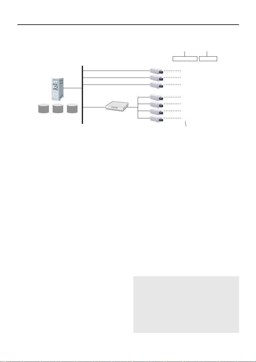
NETWORK CONNECTION
Two different types of unit can be connected to the network archiving system: network cameras and
network video servers.
Server Computer
(Image server)
Camera image dataCamera image data
IP address
IP address
IP address
Network video server
2
IP address
1 Network camera
Each network camera is connected directly to
the image server.
2 Network video server
Normal monitoring cameras are connected to
the image server via a network video server.
Up to a maximum of four monitoring cameras
can be connected to a single network video
server.
3 Camera number
This is a number that is assigned to each
camera for use in the system. Up to a
maximum of 16 cameras can be connected to
the network archiving system, so that camera
numbers from 1 to 16 are available, but the
numbers cannot be duplicated.
4 Camera ID
This is an identifier that the image server uses
to specify cameras. The camera IDs may not
be duplicated within the network archiving
system.
•
Camera IDs consist of five alphanumeric
characters.
The IDs consist of a basic ID (4 characters)
and a serial number (0 to 3). When a basic
ID is registered, the network camera or
network video server automatically assigns
the serial number.
3
1
Network camera
Monitoring camera
(Setting examples)
☞ For network cameras
Basic ID entered: CCAM → Camera ID:
CCAM0
☞ For a network video server
Basic ID entered: SCAM → Camera ID:
SCAM0 (1 to 3)
•
The Administrator registers camera IDs
at the image server.
When a camera is connected to the
network, the Administrator registers the
camera ID using the network archiving
software (Camset).
•
Camera IDs cannot be changed by
general users.
Camera IDs are camera identifiers. They
are not specific to any particular camera
unit, so if a particular camera has a
problem and needs to be replaced, you do
not need to change the camera ID.
Note: If your system requires protection
from power outages, you should use
an uninterrupted power supply
(UPS). If running the system for
extended periods, it is also
recommended that you periodically
shut the system down and restart it
in order to ensure more stable
system operation.
Camera number Camera ID
1 CCAMO
2 DCAMO
3 ECAMO
4 SCAM0
5 SCAM1
6 SCAM2
7
Maximum 16
4
SCAM3
4
English
Page 6
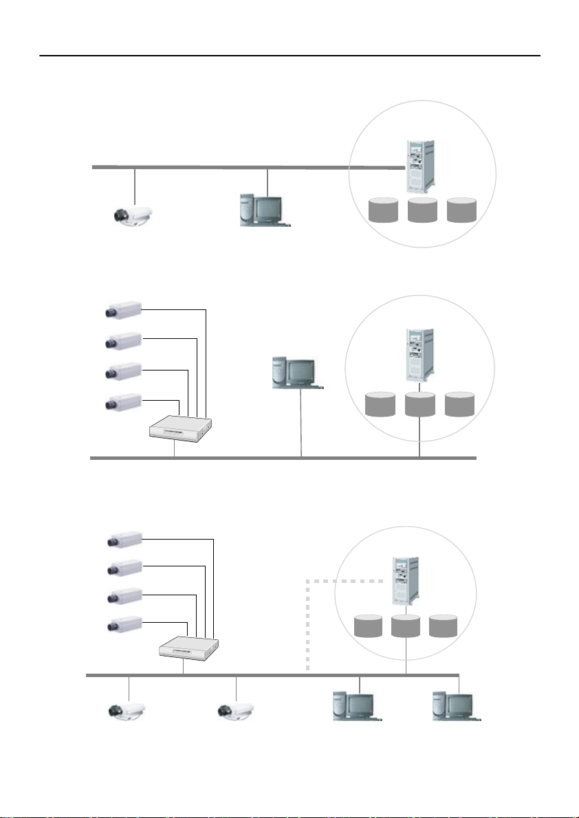
NETWORK CONFIGURATION EXAMPLE
■ When a Single Network Camera is Connected
Server computer
(Image server)
LAN
Camera image dataCamera image data
Network camera
■ When Four Cameras are Connected to a Network Video Server
Monitoring camera
Monitoring camera
Monitoring camera
Monitoring camera
LAN
Client computer
Client computer
Network
video server
Server computer
(Image server)
Camera image dataCamera image data
■ When Two Network Cameras and a Network Video Server (with Four
Cameras) are Connected
Monitoring camera
Server computer
(Image server)
Camera image dataCamera image data
LAN
English
Monitoring camera
Monitoring camera
Monitoring camera
Network
video server
Network camera Network camera
Client computer Client computer
5
Page 7
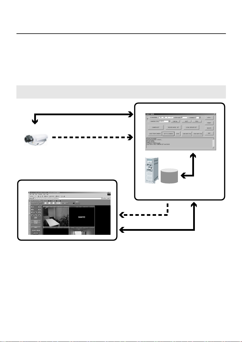
SYSTEM CONFIGURATION AND IMAGE
SERVER
In order to use this system, you need to install the network archiving software to the computer that is to
be used as the image server, and you need to install the JPEG2000 plug-in to the computers that are to
be used as the client computers.
After installing the software for this system, you can then set the recording conditions for the network
cameras and video server from the image server, and record images onto the image server.
The client computers can be used to view, search and play back images that have been recorded by the
image server.
Note: The speed of recording and viewing live/playback images is dependent on factors such
as the network environment and the computer performance.
2 Server computerSettings
1 Camera
Live images
3 Client computer
(Operation of each component)
1 Camera
This captures the images being monitored.
2 Server Computer
•
CamSet
This is a utility for setting the connection
parameters for the camera and the image
server.
•
Image server
This records the image data that is
transmitted from the cameras based on the
conditions that have been set.
(Image server)
Live images
Settings
3 Client computer
This is used as a viewing terminal to monitor,
search and play back live images and also
images that have been recorded by the image
server.
6
Settings
English
Page 8
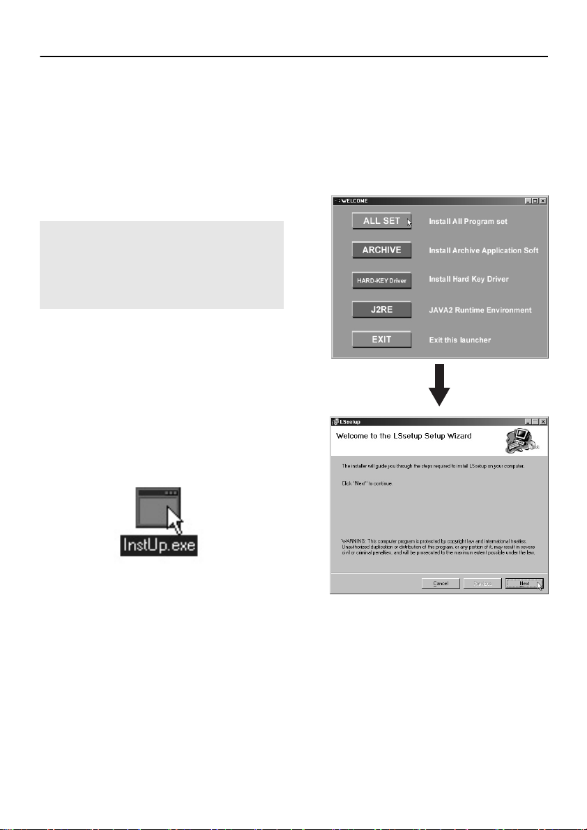
INSTALLING THE SOFTWARE
In order to use the network archiving system, you need to install the archiving software onto the image
server, and the JPEG2000 plug-in onto the client computers respectively.
2
■ Installing the Archiving Software
The archiving software consists of the following
three programs: recording software, a hardware
key driver, and J2RE (Java 2 Runtime). You
should normally select “ALL SET” so that all
three software programs are installed together.
Note: Checking for Java 2 Runtime
Before installing the software, check if
Java 2 Runtime has already been
installed on the image server. If Java 2
Runtime Ver. 1.4 or later has already
been installed, you must uninstall it.
JAVA is a trademark or registered trademark of
Sun Microsystems, Inc. in the United States of
America and other countries.
1
Place the system disk for the
archiving software into the CD-ROM
drive of the image server, and then
run ‘‘InstUP.exe’’.
The “WELCOME” window will be displayed.
Click [ALL SET] in the ‘‘WELCOME
window’’.
The installation will start, and the setup
window will be displayed.
English
Archive application software
•
(ARCHIVE)
This records JPEG2000 images.
Hardware key driver
•
(HARD-KEY Driver)
After installing the hardware key driver,
be sure to insert the accessory hardware
key into the USB port of the image server.
Java Runtime Environment (J2RE)
•
This installs Java 2 Runtime Ver. 1.3.
7
Page 9
INSTALLING THE SOFTWARE
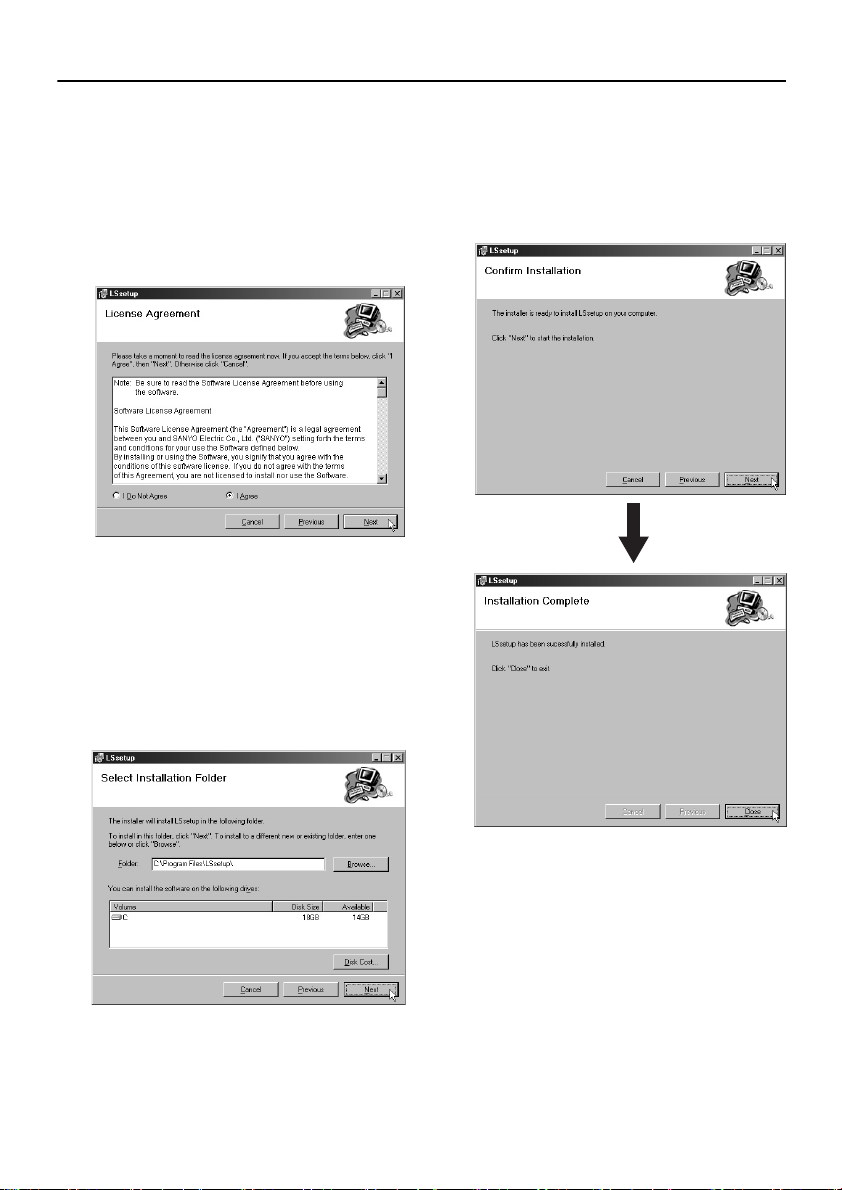
3
Click [Next] in the “ Welcome to the
LSsetup Setup Wizard” window (to
install the archive application
software).
The license agreement conditions will be
displayed. After reading the conditions
carefully, select “I Agree” if you agree to the
conditions, and then click [Next].
4
Click [Next] in the “ Select
Installation Folder” window.
Normally you should not change the default
settings. If you would like to change the
destination folder for installation of the
software, type the new folder into the box, or
click [Browse] and select the destination
folder.
5
Click [Next] in the “ Confirm
Installation” window.
Installation will then start and the progress
meter will show how far the installation has
progressed. Once the installation is
complete, click [Close].
8
English
Page 10
INSTALLING THE SOFTWARE
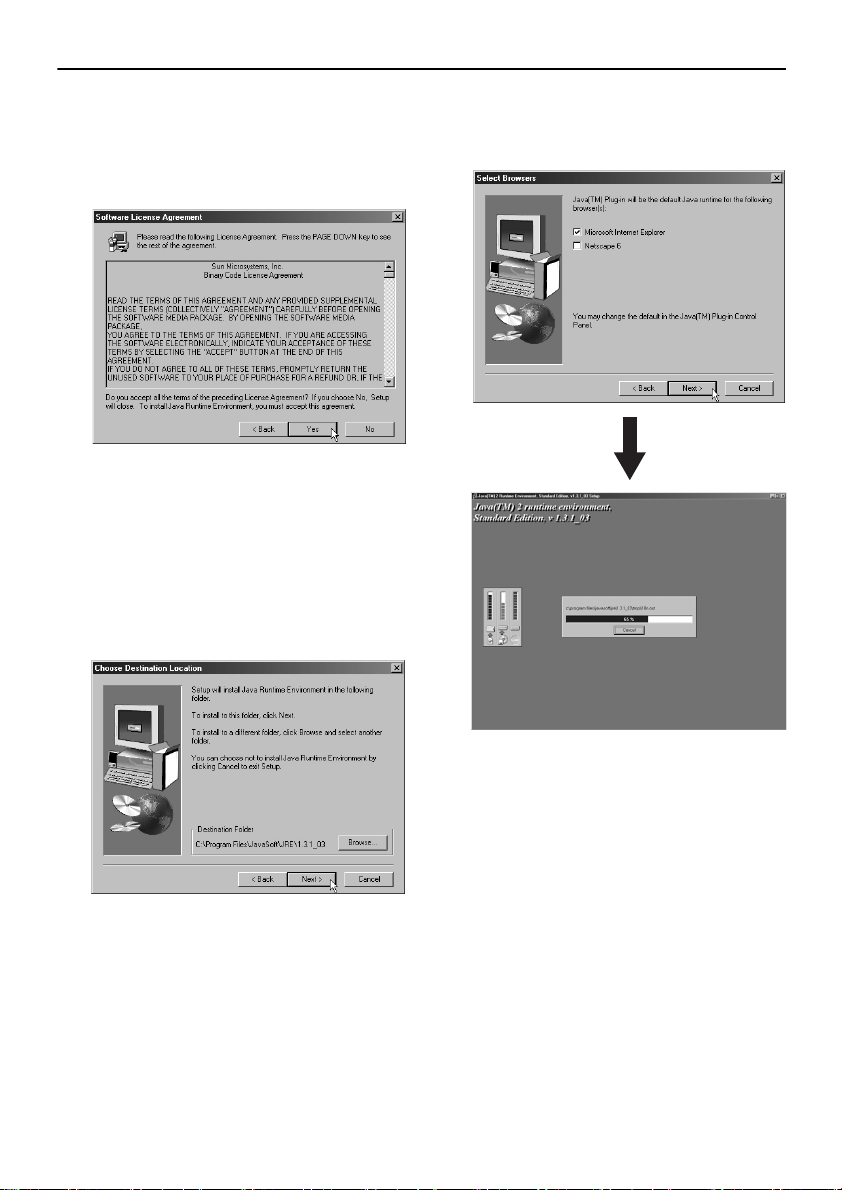
6
After this, installation of the J2RE
software starts.
The license agreement conditions will be
displayed. After reading the conditions
carefully, click [Yes].
7
Click [Next] in the “ Choose
Destination Location” window.
Normally you should not change the default
settings. If you would like to change the
destination folder for installation of the
software, type the new folder into the box, or
click [Browse] and select the destination
folder.
8
Click [Next] in the “ Select
Browsers” window.
Installation of the J2RE software will start.
English
9
Page 11
INSTALLING THE SOFTWARE
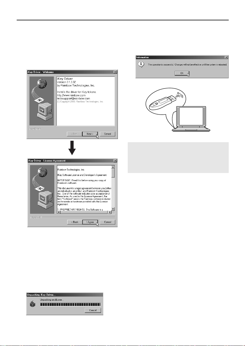
9
After this, installation of the
hardware key driver starts.
When the “iKey Driver - Welcome”
1
window is displayed, click [Next].
At the “iKey Driver - License Agreement”
2
window, click [I Agree].
11
Insert the accessory hardware key
into the USB port of the image
server.
Then click [OK].
Note: If you remove the hardware key while
the software is running, recording
will stop. To resume recording,
reinsert the hardware key and then
restart the image server.
12
After the installation is completed,
restart the image server. The
“ Camset” and “ LSsetup” shortcut
icon will appear on the desktop.
Double-click each icon.
10
The progress meter will show how
far the installation has progressed.
Once the installation is complete
and a message box is displayed,
click [OK].
When all software programs have been
installed, a message will be displayed
prompting you to restart the computer.
10
English
Page 12
INSTALLING THE SOFTWARE
■ Installing the JPEG2000 Plug-in
Install the JPEG2000 plug-in onto the client
computers from the CD-ROM. Refer to the
documentation provided with the network camera
or video server for instructions on installing the
plug-in.
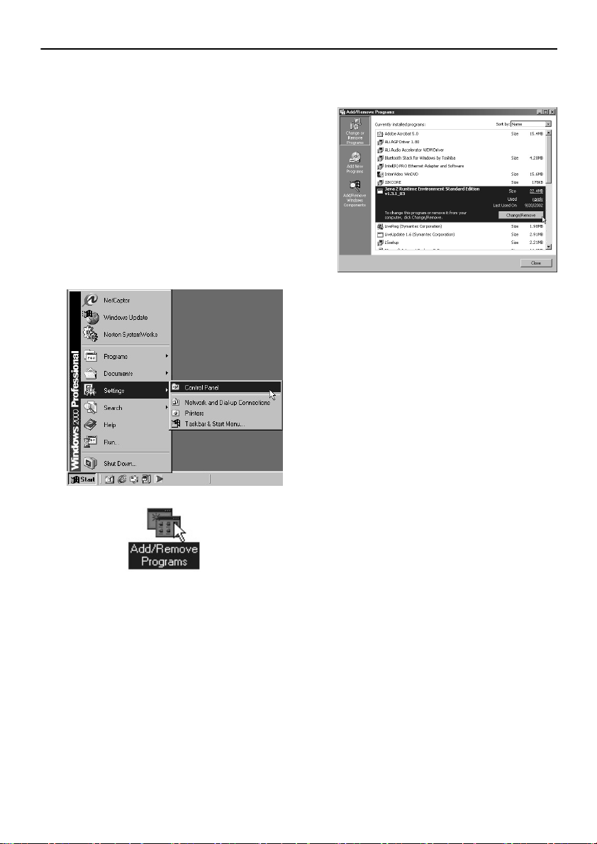
■ Uninstalling the Network
Archiving System Software
1
Click [Start] and then click [Control
Panel]. Then double-click the “ Add/
Remove Programs” icon.
2
Remove Java 2 Runtime, LSsetup
and the ikey driver.
3
Delete any data that has been stored
on the image server.
Delete the directories (cam1 to 16) that
•
have been created in the drive (example:
drive D) that has been specified in the
partition settings.
Delete the “C:/Program File/LSsetup/”
•
folder. If you changed the installation
destination folder, then delete the folder
with the path that was specified.
English
11
Page 13
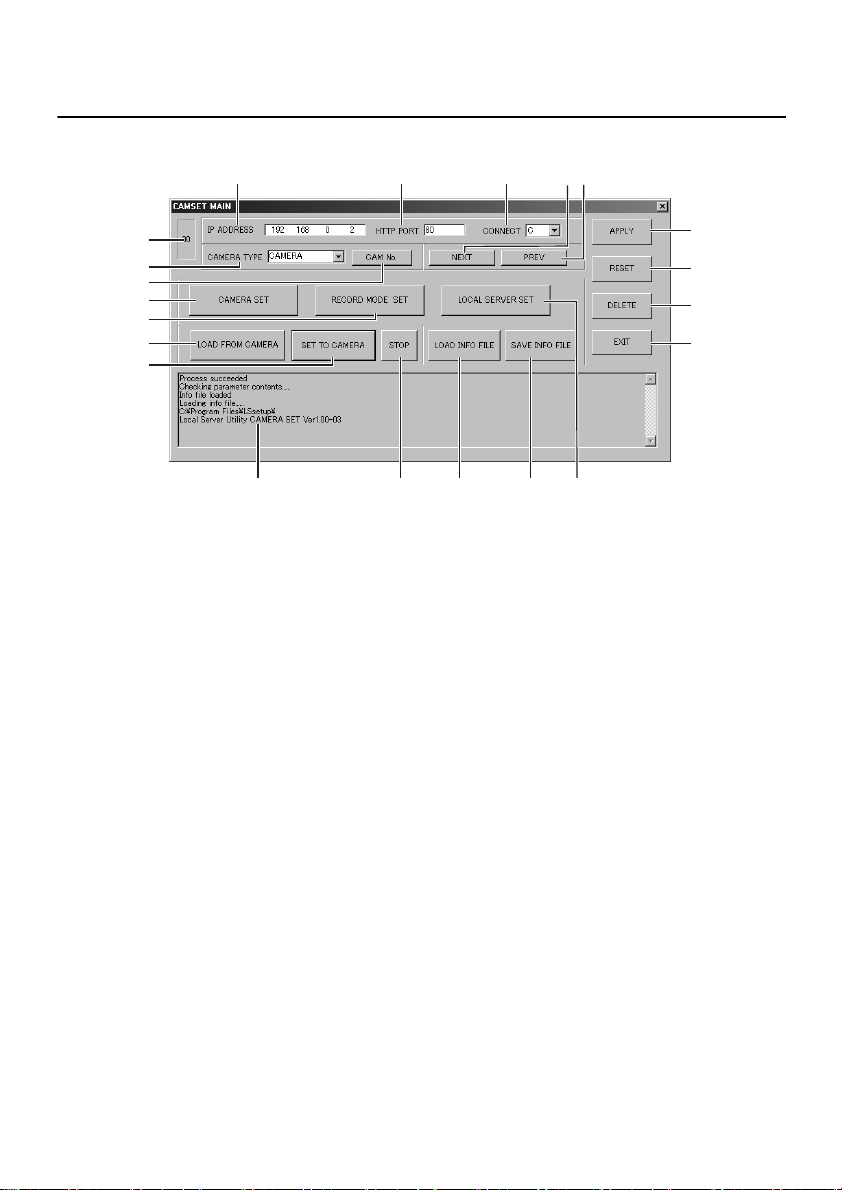
FUNCTIONS OF EACH CAMSET MAIN WINDOW
ELEMENT
Click “ Camset” shortcut icon on the desktop.
2 3
4
7
8
1
5
6
9
F
H
I
Q K L
1 Table number (00 – 15)
This shows the number of the table that is
being operated.
With Camset, information for a single camera
is stored by itself separately, and up to a
maximum of 16 tables can be edited, one for
each camera connected. The configuration
files in all tables can all be retrieved and
saved together.
2 IP ADDRESS
This is the IP address for the camera.
3 HTTP PORT (Default setting: 80)
This is the port number for the camera.
The default setting should normally be left as
it is.
4 CONNECT (Default setting: C)
This shows whether the camera can be
accessed by the image server.
Available settings:
•
C: Access to the camera is possible.
Access to the camera is not possible.
•
N:
•
If the camera is connected to the
Internet via a dial-up connection
and so the IP address is not fixed
•
If the camera is behind a firewall
and cannot be accessed directly
J
5 CAMERA TYPE
(Default setting: CAMERA)
This selects the type of camera that is
connected.
Available settings:
•
CAMERA: Network camera
•
SERVER: Network video server
6 CAM No. (p. 19)
When you click this button, the “CAMERA
No.” window is displayed.
7 NEXT
When you click this button, the display moves
to the next table. Use this when you have
finished making the settings for one camera
and you would like to make the settings for
the next camera.
If the next table has not been created yet,
•
the message “No next camera, create new
camera?” will be displayed. Click [Yes] to
create a new table.
If the table number is “15”, you cannot
•
move to the next table.
M
N
O
P
G
12
English
Page 14

FUNCTIONS OF EACH CAMSET MAIN WINDOW ELEMENT
8 PREV
When you click this button, the display moves
to the previous table.
If the table number is “00”, you cannot move
to the previous table.
Note: If using either the [NEXT] or [PREV]
operations, make sure that the [SET
TO CAMERA] operations have been
carried out correctly first in order to
ensure that no mismatches occur in
the setting information between the
camera and the configuration file.
9 CAMERA SET (p. 20)
When you click this button, the “CAMERA
SET” window is displayed.
If “SERVER” is selected as the CAMERA
TYPE setting, a warning message will be
displayed and the “CAMERA SET” window
will not be displayed.
F RECORD MODE SET (p. 22)
When you click this button, the “RECORDING
MODE SET” window is displayed.
G LOCAL SERVER SET (p. 25)
When you click this button, the “LOCAL
SERVER SET” window is displayed.
H LOAD FROM CAMERA
When you click this button, the camera setting
information is loaded into the table that is
currently being edited.
The IP address and HTTP port number for
•
the camera must be set correctly.
I SET TO CAMERA
When you click this button, the setting
information in the table is applied to the
camera.
The IP address and HTTP port number for the
camera must be set correctly.
J STOP
When you click this button, saving and
applying of camera setting information is
halted.
K LOAD INFO FILE
When you click this button, the contents of the
configuration file are loaded into the table.
L SAVE INFO FILE
When you click this button, the contents of the
table are all saved into the configuration file.
The contents of the table cannot be saved
into the configuration file in the following
cases.
If camera numbers are duplicated
•
If camera IDs have not been set or are
•
overlapping
Before saving information to the configuration
file, check the information in the table that is
being edited and make any corrections that
may be required.
M APPLY
When you click this button, the values that
have been typed in are applied to the table.
When this button is clicked, only the table
values that are currently in the memory are
overwritten. They are not yet applied to the
camera or saved in the configuration file at
this point.
N RESET
When you click this button, the settings are
returned to their previous settings.
This is only possible before [APPLY] is
clicked.
O DELETE
When you click this button, the configuration
table that is currently being edited is deleted.
P EXIT
When you click this button, Camset ends and
the main window closes.
Note: If you click [EXIT] when the contents
of the table have been changed but
they have not yet been applied to the
camera, the warning message “ Did
not Set Parameters to Camera, OK?”
will be displayed. If the changes have
also not been saved to the
configuration file, the warning
message “ Not Saved to Param File,
Exit OK?” will be displayed.
Q Log window
This displays messages showing the results
of operations.
English
13
Page 15
NETWORK CAMERA SERVER SETTINGS
Set the IP addresses.
1
Before double-clicking the shortcut icon
for the Camset network archiving system,
set the unique IP addresses for the cameras
that are connected to the image server.
Note: IP addresses cannot be set using the
Camset network archiving system.
Open the setting page for each
camera to make the settings.
2
Check the connections.
Connect the network cameras to the image
server, and check that the cameras can be
accessed using the image server.
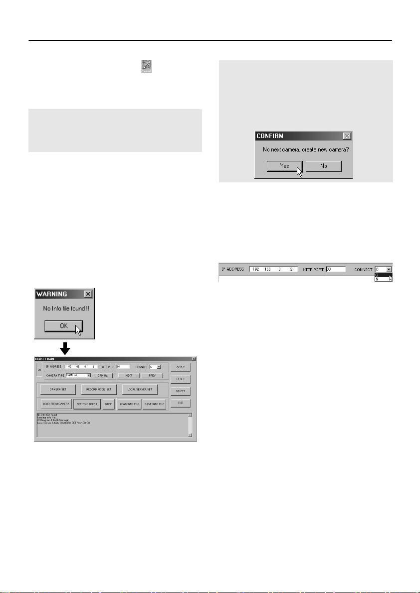
3
Double-click the “ Camset” shortcut
icon on the desktop.
A “No Info file found!!” message box will be
displayed. Click [OK] to display the
“CAMSET MAIN” window. This window is
the “00” configuration file.
Note: To load a different configuration file,
click [NEXT]. The CONFIRM dialog
box will be displayed with the
message “ No next camera, create
new camera?” , so click [Yes] to load
another configuration file.
Type in the IP address for the
4
camera with the default settings,
select “ C” or “ N” from the
“ CONNECT” drop-down list box,
and then click [APPLY].
5
Select the CAMERA TYPE setting.
Select “CAMERA” or “SERVER” from the
drop-down list box.
14
English
Page 16
NETWORK CAMERA SERVER SETTINGS
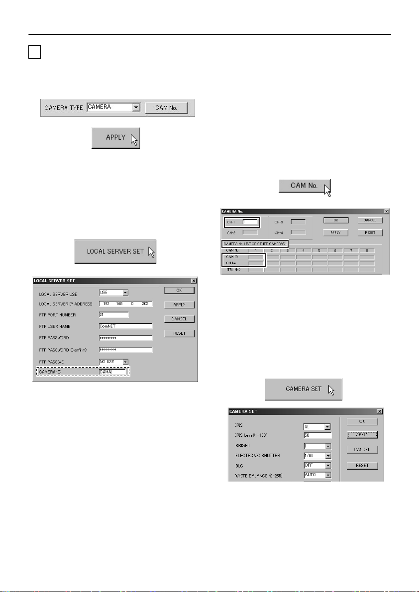
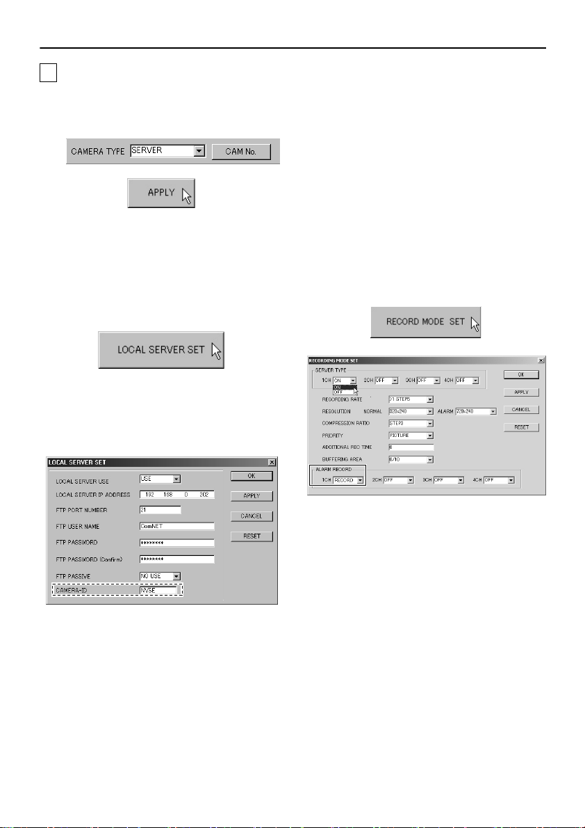
AIf “ CAMERA” is selected as the CAMERA TYPE setting
1
Select “ CAMERA” and then click
[APPLY].
2
Click [LOCAL SERVER SET].
The “LOCAL SERVER SET” window will be
displayed. Use this window to make the
settings for server. For further details, refer
to “FUNCTIONS OF EACH LOCAL
SERVER SET WINDOW ELEMENT”.
(p. 25)
4
Click [CAM No.].
The “CAMERA No.” window will be
displayed. While referring to “CAMERA No.
LIST OF OTHER CAMERAS”, type in a
camera number in the “CH-1” box that does
not overlap with an existing camera number.
The ID corresponding to the “CAMERA-ID”
entry in the “LOCAL SERVER SET” window
will be displayed in the “CAM ID” column.
(p. 26)
5
Click [APPLY] and close the
window.
6
Click [CAMERA SET].
The “CAMERA SET” window will be
displayed. Make the camera settings, and
then click [APPLY] and close the window.
(p. 20)
3
Type in a 4-character camera ID in
the “ CAMERA-ID” box, click
[APPLY] and then close the “ LOCAL
SERVER SET” window.
English
15
Page 17
NETWORK CAMERA SERVER SETTINGS
☞
Copying camera setting information
Camera settings are normally made in the
“CAMERA SET” window, but you can also
copy existing camera settings and apply them
to other cameras.
1
Click [LOAD FROM CAMERA].
The information for the camera that has
already been set will be loaded. It may
take several seconds for this information
to load.
2
Click [CAMERA SET].
The “CAMERA SET” window will be
displayed. Change any information that is
necessary, and then click [APPLY] and
close the window.
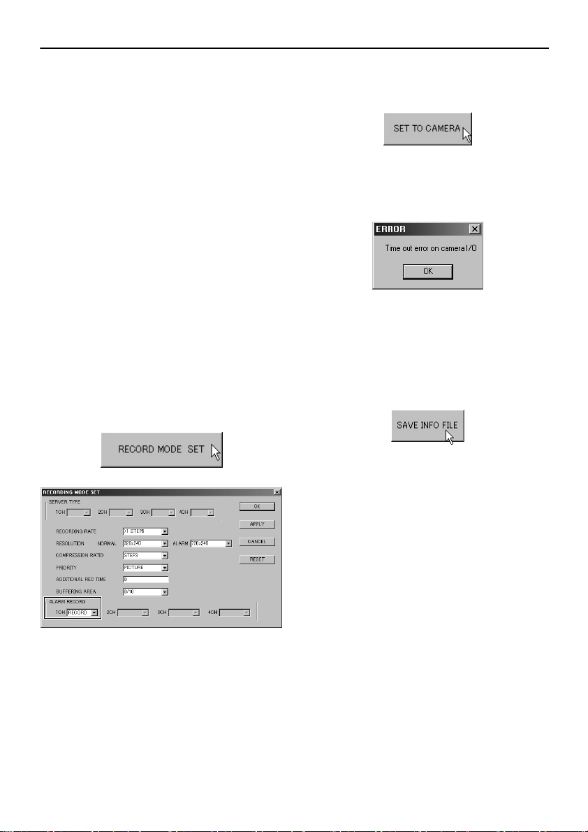
Click [RECORD MODE SET].
7
The “RECORDING MODE SET” window will
be displayed. Set the items that are required
for recording. (p. 22)
☞
If alarm recording is to be carried out
Change the setting in the drop-down list
box for “1CH” in the “ALARM RECORD”
box to “RECORD”, and then click
[APPLY] and close the window.
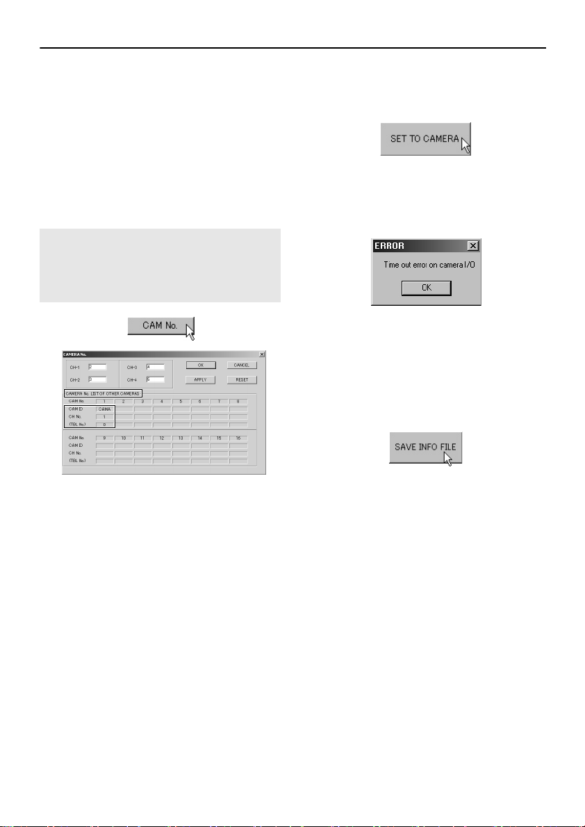
Click [SET TO CAMERA].
8
The setting information will be applied to the
camera.
It may take several seconds for the
information to set. If the camera is not
connected correctly, the following error
message will be displayed.
Click [SAVE INFO FILE].
9
The setting information will be saved in the
configuration file.
If saving setting information into other
configuration files, repeat the above
procedure.
16
English
Page 18
NETWORK CAMERA SERVER SETTINGS
BIf “ SERVER” is selected as the CAMERA TYPE setting
1
Select “ SERVER” and then click
[APPLY].
2
Click [LOCAL SERVER SET].
The “LOCAL SERVER SET” window will be
displayed. Use this window to make the
settings for server. For further details, refer
to “FUNCTIONS OF EACH LOCAL
SERVER SET WINDOW ELEMENT”.
(p. 25)
3
Type in a 4-character camera ID in
the “ CAMERA-ID” box, click
[APPLY] and then close the “ LOCAL
SERVER SET” window.
4
Click [RECORD MODE SET].
The “RECORDING MODE SET” window will
be displayed. Use the drop-down list boxes
to set whichever of the four “SERVER
TYPE” channels that is displaying camera
images to “ON”, and change any other
settings that may be required. For details,
refer to the “RECORDING MODE SET”
window. (p. 22)
If alarm recording is to be carried out,
•
change the setting in the drop-down list
box for “CH” in the “ALARM RECORD”
box to “RECORD”, and then click
[APPLY] and close the window.
English
17
Page 19
NETWORK CAMERA SERVER SETTINGS
Click [CAM No.].
5
The “CAMERA No.” window will be
displayed. While referring to “CAMERA No.
LIST OF OTHER CAMERAS”, type in the
camera numbers in the “CH-1” to “CH-4”
boxes that do not overlap with existing
camera numbers.
The ID corresponding to the “CAMERA-ID”
entry in the “LOCAL SERVER SET” window
will be displayed in the “CAM ID” column.
(p. 26)
Note: The “ SERVER TYPE” in the
“ RECORDING MODE SET” window
must be set to “ ON” to be able to
type a camera number into the
corresponding boxes.
7
Click [SET TO CAMERA].
The setting information will be applied to the
camera.
It may take several seconds for the
information to set. If the camera is not
connected correctly, the following error
message will be displayed.
Click [SAVE INFO FILE].
8
The information that is recorded in the
configuration file for the image server will be
saved.
If saving setting information into other
configuration files, repeat the above
procedure.
6
Click [APPLY] and close the
window.
18
English
Page 20
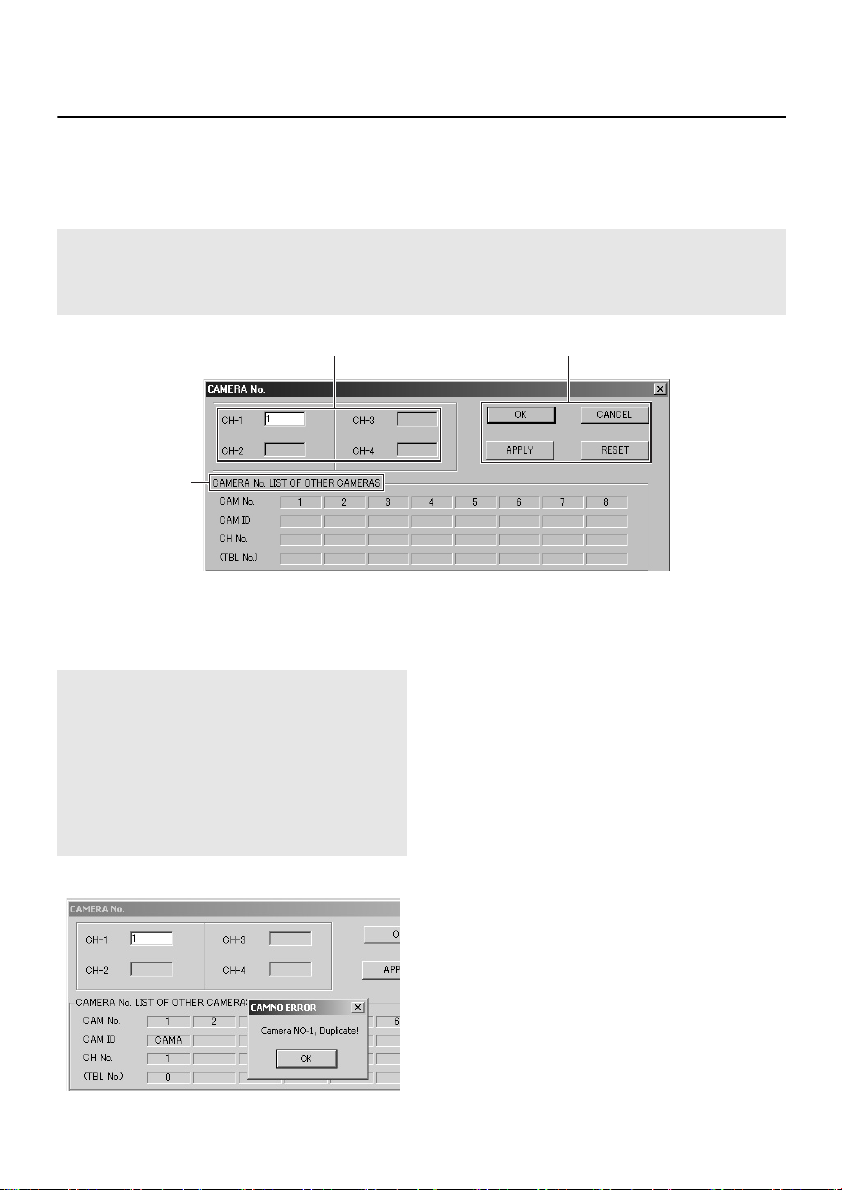
FUNCTIONS OF EACH CAMERA No. WINDOW
ELEMENT
This window lets you assign numbers (1 to 16) to each channel for the cameras that are connected to
the image server. These numbers are used for system administration purposes.
Click [CAM No.] in the “ CAMSET MAIN” window.
Note: If assigning a camera number to a network camera, only “ CH-1” can be set. For a
network video server, the channels that can be set are the available channels (up to a
maximum of four) in which the camera connection is set to “ ON” in the “ RECORDING
MODE SET” window.
1 3
2
1 Camera number settings
Type the camera numbers into the camera
number boxes.
Note: For example, if a camera setting has
been made for “ CAM No. 1” in the
“ CAMERA No. LIST OF OTHER
CAMERAS” box and you then set
“ CH-1” to “ 1” , the settings will
overlap and the “ CAMNO ERROR”
message box will be displayed. The
duplicated setting will not be applied
even if you click [OK].
English
2 CAMERA No. LIST OF OTHER
CAMERAS
This shows the camera numbers that have
already been set in other tables.
CAM ID: This shows the ID that was
•
CH No.: For network cameras, “1”
•
(TBL No.): This shows the number for the
•
typed into the “CAMERA-ID”
box in the “LOCAL SERVER
SET” window.
(CH) is displayed, and for
network video servers, 1 – 4
(CH) is displayed.
corresponding table in the
“CAMSET MAIN” window.
3 Table settings
These buttons function in the same way as
the buttons
CAMERA SET WINDOW ELEMENT”. (p. 21)
in “FUNCTIONS OF EACH
F
19
Page 21
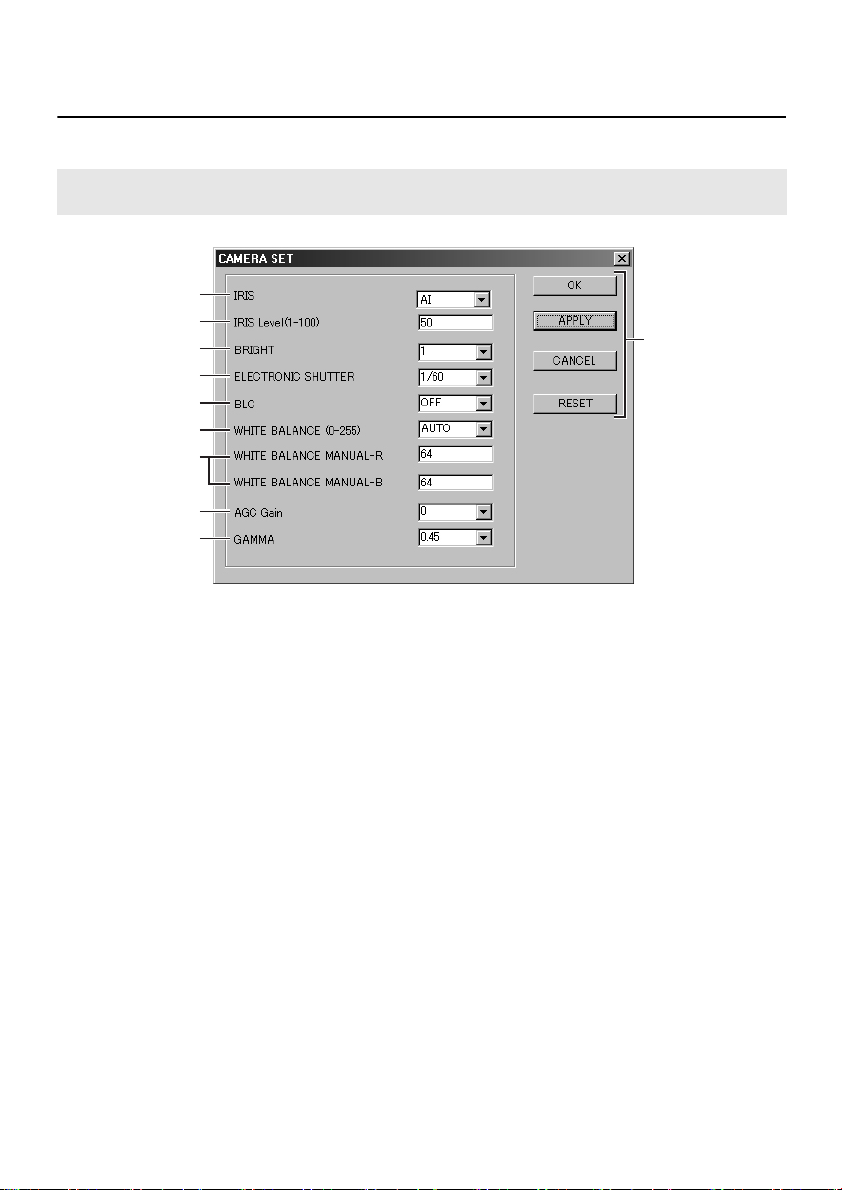
FUNCTIONS OF EACH CAMERA SET WINDOW
ELEMENT
This window lets you make detailed settings that determine the camera operating parameters.
Note: If “ SERVER” is selected as the CAMERA TYPE setting, a warning message will be
displayed and the “ CAMERA SET” window will not be displayed.
1
2
3
4
5
6
7
8
9
F
1 IRIS (Default setting: AI)
Select the iris setting from the drop-down list
box.
Available settings:
•
AI: Automatic iris
Electronic iris
•
EI:
2 IRIS Level (Default setting: 50)
Type the iris level in the text box. The larger
the value, the greater the iris level.
Available settings: 1 to 100
3 BRIGHT (Default setting: 1)
Select the image brightness from the dropdown list box. The brightness can be set to
one of five levels, and the higher the value,
the brighter the images.
Available settings: 1 to 5
4 ELECTRONIC SHUTTER
(Default setting: 1/60)
This setting can be changed when IRIS is set
to “AI”.
Select the electronic shutter speed (8 speeds)
from the drop-down list box.
Available settings:
1/60, 1/100, 1/250, 1/500, 1/1000, 1/2000,
1/4000, 1/10000 sec.
5 BLC (Default setting: OFF)
Select the backlight correction function from
the drop-down list box.
Available settings:
•
OFF: Backlight correction is not
•
MULTI: Multiple point photometry;
•
CENTER: Center focus photometry;
carried out.
backlight correction is
calculated from the whole
image.
backlight correction is
calculated based on the center
of the image.
20
English
Page 22

FUNCTIONS OF EACH CAMERA SET WINDOW ELEMENT
6 WHITE BALANCE
(Default setting: AUTO)
Select the white balance (automatic color
temperature correction) from the drop-down
list box.
Available settings:
AUTO: Automatic white balance; the
•
INDOOR: This setting is for when the
•
OUTDOOR: This setting is for when the
•
MANUAL: Manual white balance; this
•
white balance is adjusted
automatically to obtain correct
colors even if the light source
changes.
camera is being used indoors
under fluorescent lighting.
camera is being used
outdoors under natural
sunlight.
can be used when the
“AUTO” setting does not give
correct color reproduction.
7 WHITE BALANCE MANUAL-R/B
(Default setting: 64)
This is used when “WHITE BALANCE” is set
to “MANUAL”. Type in the color sensitivity
level for red (R) or blue (B) in the text box.
Available settings: 0 to 255
8 AGC Gain (Default setting: 0)
This sets the image capture sensitivity. Select
the AGC (automatic gain control) gain level
from the drop-down list box. If the images are
too dark, increase the gain level.
Available settings: –6dB, 0, +6dB, +9dB,
OFF
9 GAMMA (Default setting: 0.45)
Select the gamma correction value (signal
correction value/contrast for natural images)
from the drop-down list box.
Available settings: 1, 0.8, 0.6, 0.45, 0.3
Note: Refer to the documentation provided
with the network cameras for details
on settings for other cameras. In
addition, other settings such as
those for motion sensors that can
only be made at the camera itself
should basically be made first before
any other settings are made.
When you change the settings in this
setting window, always make sure
that the changed settings are
updated in the camera window also.
F Table settings
OK
•
The data that has been typed in is applied
to the table that is currently being edited,
and the window closes.
APPLY
•
The data that has been typed in is applied
to the table that is currently being edited,
but the window does not close.
CANCEL
•
The data that has been typed in is
discarded, and the window closes. (This is
only possible before [APPLY] is clicked.)
RESET
•
The data that has been typed in is
discarded, and the previous table settings
are restored. (This is only possible before
[APPLY] is clicked.)
English
21
Page 23

FUNCTIONS OF EACH RECORDING MODE SET
WINDOW ELEMENT
This window lets you set the camera recording parameters.
Click [RECORDING MODE SET] in the “ CAMSET MAIN” window.
1
2
3
4
5
6
7
8
1 Channel connection settings
If the camera type is a network video server,
you can set the connection (ON/OFF) to the
image server for each channel (CH1 to CH4)
in the “SERVER TYPE” drop-down list boxes.
(You cannot change any settings here if the
camera is a network camera.)
2 RECORDING RATE
Select the recording rate (image transmission
speed) from the drop-down list box.
Available settings: 0.1 to 1.0, >1 STEP 1 to
>1 STEP 5
Note: The transmission speed may be
limited by the conditions of the
network environment that is being
connected to.
3 RESOLUTION
Select the resolutions for both normal
recording and alarm recording from the dropdown list boxes.
The higher the resolution, the greater the
volume of data transferred.
Available settings:
•
NORMAL: 720x480, 720x240, 640x480,
320x240, 160x120
(Default setting: 320x240)
•
ALARM: 720x480, 720x240
(Default setting: 720x240)
9
22
English
Page 24

FUNCTIONS OF EACH RECORDING MODE SET WINDOW ELEMENT
4 COMPRESSION RATIO
Select the compression ratio for image data
that is used by the image processing circuit
for each recording mode from the drop-down
list boxes.
Available settings: STEP 1 to STEP 5
The compression ratio setting can be set
to one of five steps, from STEP 1 (high) to
STEP 5 (low). If a higher compression ratio
is used, the volume of image data
becomes smaller (the amount of image
deterioration becomes greater) but the
transmission speed becomes faster.
5 PRIORITY
Select the priority mode for recording from the
drop-down list box.
Available settings:
PICTURE: Recording is carried out at high
•
TIME: Recording is carried out at
•
quality.
normal quality.
(The duration for recording
alarm data is shorter.)
6 ADDITIONAL REC TIME
When an alarm occurs, images are recorded
by the image server in accordance with the
alarm memory area of the camera, but you
can extend the recording time by typing in an
additional time in seconds.
Available settings: 0 to 300 sec.
7 BUFFERING AREA
Select the ratio for allocating pre-alarm
recording and post-alarm recording space in
the camera’s alarm memory area from the
drop-down list box.
Example 0/10
Post-alarm recording area
Pre-alarm recording area
Available settings: 0/10, 1/9, 2/8, 3/7, 4/6,
When setting the pre-alarm recording
•
area (the setting range is from 1/9 to 5/
5), the compression ratio and resolution
that have been set as the alarm
recording conditions will also be applied
to normal recording and will be fixed at
those settings, so that it will not be
possible to change the compression
ratio and resolution for normal
recording.
If the “ BUFFERING AREA” setting is
•
something other than “ 0/10” (if a prealarm recording area has been set), the
following checks will be carried out
automatically when [OK] or [APPLY] is
clicked.
Are the RESOLUTION settings for
☞
normal and alarm recording the
same?
If they are different, a warning message
is displayed, and the RESOLUTION
setting for alarm recording is adopted
for both kinds of recording.
5/5
☞ Does the COMPRESSION RATIO
setting match the PRIORITY setting?
If the settings are not as follows, a
warning message is displayed and the
settings are forcibly adjusted.
PRIORITY (PICTURE)
•
COMPRESSION RATIO (STEP 5)
PRIORITY (TIME)
•
COMPRESSION RATIO (STEP 2)
English
23
Page 25

FUNCTIONS OF EACH RECORDING MODE SET WINDOW ELEMENT
8 ALARM RECORD
Select the alarm recording function setting for
the camera from the drop-down list box.
Available settings:
•
RECORD: The alarm recording function is
•
OFF: The alarm recording function is
enabled.
disabled.
9 Table settings
These buttons function in the same way as
button
F in “FUNCTIONS OF EACH
CAMERA SET WINDOW ELEMENT”. (p. 21)
■ Alarm Recording
This system allows two modes of recording to be
carried out. These modes are normal recording
and alarm recording. Normal recording is the
default mode; alarm recording starts
automatically when an outside intruder triggers
an alarm.
Alarm recording consists of “pre-alarm
recording” which records the images
immediately before an alarm occurs, and “post-
alarm recording” which records the images
immediately after the alarm occurs.
The following two types of alarm detection can be
used by the cameras.
•
Detection by means of an external alarm
sensor
This uses a response from a sensor such as
an infrared sensor to input external alarm data
to the camera.
•
Detection by means of a motion sensor
This uses the motion detection function that
has been set at the camera to automatically
detect any movement in the images being
recorded.
Note: The alarm detection functions of the
camera cannot be set or changed at
the image server.
24
English
Page 26

FUNCTIONS OF EACH LOCAL SERVER SET
WINDOW ELEMENT
This lets you set the attribute information (such as IP address and port number) for the image server.
Click [LOCAL SERVER SET] in the “ CAMSET MAIN” window.
1
2
3
4
5
6
7
8
9
1 LOCAL SERVER USE
Select whether the image server is to be used
or not from the drop-down list box.
Available settings:
NO USE: Not used
•
USE: Used
•
Note: If “ USE” is selected, a special mode
will be activated so that direct
connections between the browser
and network cameras and video
servers can only be made by the
Administrator (ID3). Refer to the
documentation provided with the
network camera or video server for
details on browser connections.
2 LOCAL SERVER IP ADDRESS
Type in the IP address for the image server in
the text box.
English
3 FTP PORT NUMBER
Type in the FTP (File Transfer Protocol) port
number for the image server in the text box.
Normally you should type in “21”.
4 FTP USER NAME
(Default setting: ComNET)
Type in the FTP username in the text box.
5 FTP PASSWORD
Type in the FTP password in the text box.
(The password can be up to 16 characters in
length. The password entered is casesensitive.)
25
Page 27

FUNCTIONS OF EACH LOCAL SERVER SET WINDOW ELEMENT
6 FTP PASSWORD (Confirm)
Re-enter the FTP password in the text box to
confirm it.
If the two passwords are different, the
message “PassWord Not Match” will be
displayed when you click [APPLY].
7 FTP PASSIVE
(Default setting: NO USE)
If the FTP connection is in passive mode, set
to “USE”. However, this should normally be
set to “NO USE”.
Available settings:
•
NO USE: Not used
•
USE: Used
Note: The use or non-use of passive mode
will vary depending on the network
configuration of the image server.
This is set to “ USE” if the camera
images cannot be seen at the image
server.
8 CAMERA-ID
This is a 4-character camera title that is
displayed for convenience at the user
terminal.
Note: If the CAMERA-ID is less than 4
characters, or if it is the same as the
CAMERA-ID that has already been
set for another camera, a warning
message will be displayed and [OK]
and [APPLY] will not work.
If you enter any more than four
characters, the extra characters will
be ignored.
9 Table settings
These buttons function in the same way as
button
CAMERA SET WINDOW ELEMENT”. (p. 21)
in “FUNCTIONS OF EACH
F
26
English
Page 28

FUNCTIONS OF EACH IMAGE SERVER
WINDOW ELEMENT
■ Main Window
When you double-click the shortcut icon on the desktop, the main window for the archiving
software will open.
The main window contains a variety of different confirmation and checking functions in the one window,
but some of the menus that are available to the user are restricted during normal system operations. As
a result, items and menus that are not described in this instruction manual cannot be used.
Note: The functions in this window cannot be used when the color of the characters in the
menu bar is gray.
21 3 4
Record indicator
1
FTP indicator
SILS indicator
Lights blue while the image server is in
operation, and lights red when the image
server is stopped.
Frame rate
2
English
now Date/Time
3
Shows the current date and time.
Start/Stop
4
These buttons are used to start and stop
server functions (recording, FTP and SILS).
Start: Click to start an operation.
•
Stop: Click to stop an operation.
•
Note: ‘‘WSftpd’’ and
‘‘C:\WINNT\system32\cmd.exe’’ will
also be run when the main window is
opened. These are not directly
related to settings, but they must not
be closed.
27
Page 29

FUNCTIONS OF EACH PARTITION SETTING
WINDOW ELEMENT
The hard disk recording areas are set according to the recording mode to be used. This window is used
to set the normal recording area and the alarm recording area.
Click on [Setting] in the menu bar and then select [Partition] from the drop-down list box. The “Partition”
window will then open.
Note: Settings cannot be carried out using
the menu bar while recording is
stopped.
1 2
3
4
Return
1
Click to return to the main menu.
Refresh
2
Click to refresh the window with the latest
information.
HDD Capacity
3
Shows the amount of free space on all hard
disk drives separately for each drive.
Count of Connected Camera
4
Shows the number of cameras that are
connected to the image server.
Image Record Partition
5
Setting box for hard disk partitions.
28
5
English
Page 30

PARTITION SETTINGS
Set the recording areas by following the procedure below.
1
Specify the drive. (Image Record
Drive)
Select the drive from the drop-down list box.
Refer to the “System Information” box in the
window for details on the amount of free space
available on each drive.
2
Set the total size of the recording area.
(Size of Data Area)
Set the size of the recording area from the
drop-down list box.
Available settings: Units of 1 Gbyte
3
Set the size of the alarm recording
area. (Alarm area)
Select the percentage of the total recording
area that is to be allocated as the alarm
recording area from the drop-down list box.
The size of the normal recording area automatically becomes the amount left over when the size of
the alarm recording area is deducted from the size of the total recording area.
Available settings: 0 to 99%
4
Confirm the number of cameras that are being used for recording. (Count of
Camera)
Refer to “Count of Connected Camera” in the “System Information” box and set the number of
cameras that are being recorded by the image server.
5
Apply the partition settings.
Click [Make] to apply the partition settings for the image server.
■ Deleting Recorded Data
If you click [Data Clear], all recorded data will be deleted. In addition, if you click [All Clear], the partition
settings will be deleted.
Note: When selecting the drive to use for recording, it is recommended that you do not select
the “ C” drive if this drive is also being used as the system drive. If selecting the “ C”
drive as the drive to use for recording, make sure that there is sufficient free space
available on the drive to allow the system to operate stably.
English
29
Page 31

CLIENT COMPUTERS
Images that are recorded onto the image sever and live images can be viewed, searched and played
back by client computers. The user levels for accessing client computers on the network are divided into
two levels: “Administrator” and “General user”. The user levels are recognized during login according
to the username and password entered. Refer to page 60 for further details on user levels.
2 Server computerSettings
1 Camera
3 Client computer
(For Administrator)
Live images
Live images
Settings
(Image server)
Settings
(For General user)
30
English
Page 32

NETWORK ARCHIVING SYSTEM SETTINGS
Start the image server.
1
2
Start the computer’s web browser.
Browser: Internet Explorer Ver. 5.5,
•
Operating system: Windows 98 SE / Me /
•
3
Type the image server’s IP address
into the browser’s location bar and
press [Enter].
Example: http://192.168.0.202/
4
Type the username and password
into the verification window as
shown below, and then click [OK].
Once the username and password have
been verified, the language selection
window will be displayed.
User Name: ADMINISTRATOR
•
Password: ADMINISTRATOR
•
Service Pack 2 or later
2000 / XP
5
Select the language and then click
[OK].
The system window will then be displayed.
Note: To discontinue receiving images
from the image server, be sure to
click the network disconnect button.
Note:
The default settings for the username and
•
password are as shown above. Refer to
page 55 for instructions on changing the
password. The username cannot be
changed.
If you click [CLEAR], the settings that
•
have been typed in will be cleared.
If you type in an incorrect username or
•
password, a message will be displayed,
so type in the correct details.
For system security, you should change
•
the password periodically.
English
31
Page 33

FUNCTIONS OF EACH SYSTEM WINDOW ELEMENT
The user can display images from the image server in the system window, and also carry out operations
such as monitoring and recording live images and playing back alarm recording images.
9 F
1
2
3
4
5
6
7
8
1 Control panel
These buttons can be used when images
have been recorded by the image server.
•
Alarm skip buttons (B C)
•
Speed buttons (D E)
D: If clicked during normal playback, the
playback speed decreases as follows
each time the button is clicked.
1/2, 1/5, 1/10, 1/20, 1/50 (relative
speed)
E: If clicked during normal playback, the
playback speed increases as follows
each time the button is clicked.
2, 5, 10, 20, 50 (relative speed)
•
Reverse playback button (F)
•
Stop button (G)
•
Playback button (H)
Note: After a search has been carried
out, the playback button can be
used to play back images from the
set time onward.
•
Frame advance buttons (I, K)
•
Pause button (J)
•
Skip to top button ( )
G
2 Search setting button (SEARCH)
Used to search and play back recorded
images by date.
3 Alarm list display button (ALARM)
Used to display the alarm conditions in list
form.
4 Menu setting display button (MENU
SETTING) (p. 43)
Used to display and set time and recording
area information. This button can only be
used by an Administrator. It is not displayed
when general users are logged in.
5 System setting window display
button (SYSTEM) (p. 53)
Used to set network and user information.
This button can only be used by an
Administrator. It is not displayed when
general users are logged in.
6 Previous window display button
(BACK)
When clicked, the display changes to the
previously-displayed window.
32
English
Page 34

FUNCTIONS OF EACH SYSTEM WINDOW ELEMENT
7 Mode select buttons (AUTO/FINE)
Images from the image server are
compressed into JPEG2000 format and are
displayed as live images. These mode select
buttons are used to select whether the
transmitted images are adjusted
automatically to the resolution that best suits
the performance of the computer being used
to view the images, or whether the resolution
is set to fine quality regardless of the
computer’s performance.
AUTO: Image resolution is automatically
•
Note: The image resolution will vary
FINE: Images are displayed at fine
•
adjusted in accordance with the
computer’s performance (default
setting).
according to the computer’s
performance. If this may be a
problem, you should change the
setting to “ FINE” . However, the
display speed may become
slower when “ FINE” is selected.
resolution.
8 Network disconnect button
Click this button to close the connection
between the computer and the image server.
“SANYO NETWORK ARCHIVING SYSTEM,
THE UNIT IS DISCONNECTED!” will be
displayed, and the camera will be
disconnected from the network.
9 Window setting buttons
Select the desired settings from the dropdown list boxes and then click the [SET]
button.
BA D EC
A Split screen number setting
(SCREEN)
Select the number of split screens to be
displayed in the image area.
Available settings: 1, 4, 9, 16
(Split screens)
B Window select button (CH)
The numbers in the drop-down list box
correspond to each split screen window.
The selected channel (CH) number is
displayed in the left part of the title bar for
the respective window.
Available settings: 1 to 16
C Camera number select button
(CAMERA)
This selects the camera number. The
camera numbers displayed are the
numbers that have been set in the “CAM
No.” window of the Camset software.
Available settings: 1 to 16
D Image mode select button (MODE)
This selects the image mode for
displaying images in the image areas.
LIVE: Monitoring of live (camera)
•
•
images
PLAY: Playback of recorded images
E SET button
Click to accept the current settings.
F
Alarm detection check button (ALARM)
This button lets you check alarm images that
have not been played back.
AB
A Alarm display
Normally these are all grayed out. When
an alarm is detected, they illuminate
orange in order starting from the right side,
and the number of the camera where the
alarm was detected is displayed. When a
button is clicked, the corresponding alarm
playback screen is displayed. (p. 41)
B Remaining alarm playback display
If there are more than three alarms that
have not yet been played back, the i
button lights red. If there are less than two
alarms in the alarm list with a playback
history of “1”, this button remains black.
Note:
Once an alarm has been played
back, the corresponding indicator
is removed from the alarm
detection check buttons. (p. 41)
English
33
Page 35

FUNCTIONS OF EACH SYSTEM WINDOW ELEMENT
G Live & playback image area
This area is used to display live images and
playback images. A maximum of 16 windows
can be set. The camera information that has
been set in the “CAMERA SET” window is
displayed in the title bars of each window.
A B C D E
A Channel number
B Camera ID
This shows the 5-character ID that has
been set in the “LOCAL SERVER SET”
window of the image server.
C Camera title
This shows the title that has been set in
the “CAMERA SET” window.
D Date and time
This shows the date and time that has
been set at the image server.
E Image mode
This shows “LIVE” or “PLAY”.
Note: The camera information display in
the title bar is abbreviated when
there are many split-screen
windows open.
Title bar functions
•
When characters are displayed in white:
Recording is stopped
•
When characters are displayed in yellow:
Recording is in progress
•
When the title bar is green:
The window is active (The settings made using
the window setting buttons 9 are applied to
the active window.)
F
F Image area
When the “ SANYO” characters in the
middle of the screen are white:
No network camera or video server is
•
connected
No images could be found for search
•
playback.
When the “ SANYO” characters in the
middle of the screen are red:
No images are being sent from the
•
image server.
34
English
Page 36

FIELD MENU OPERATIONS
If you move the mouse pointer over an image in a window in the image
display area and click the right mouse button, a pop-up menu is displayed.
This menu lets you select operations such as displaying image information
and recording and saving images.
“Live” is displayed during playback mode
1
Displaying image information (Info)
If you click “Info”, the information for the
current camera is displayed in the window.
Click [OK] to clear the information display.
Note: Refer to the “ RECORDING MODE
SET” window at the image server for
details on the values for
ResolutionLevel, CompressionRatio
and FrameRate.
2
Changing the image mode (Live /
Play)
If you click “Live” or “Play”, the following
display appears. Click [OK] to clear the
display.
“Play” is displayed during live image
•
mode (“LIVE” is displayed in the title bar).
If you click “Play”, the image mode
changes to playback mode.
•
(“PLAY” is displayed in the title bar). If you
click “Live”, the image mode changes to live
image mode.
3
Selecting recording (Rec / Stop)
(For Administrator only)
This function can only be used by an
Administrator. It is not displayed when
general users are logged in.
If recording by the corresponding camera
•
is stopped, “Rec” is displayed. If you click
“Rec”, recording starts at the image
server.
When recording starts, the
☞
characters in the title bar change to
yellow.
If recording by the corresponding camera
•
is in progress, “Stop” is displayed. If you
click “Stop”, recording stops at the image
server.
When recording stops, the
☞
characters in the title bar change to
white.
English
35
4
Saving images (Save (S))
Click “Save (S)” at the window that is
displaying the image to be saved. The
image save dialog box will be displayed.
Check the saving location and filename, and
then click [Save]. The image that was
displayed at the point where the window
was clicked will be saved.
Page 37

FUNCTIONS OF EACH SEARCH WINDOW
ELEMENT
Click [SEARCH] in the “ SYSTEM”
window.
1 2 3
1 MONTH
Used to select the month for images to be
searched.
2 DAY
Used to select the day for images to be
searched.
3 YEAR
Used to select the year for images to be
searched.
4 TIME
Used to select the time for images to be
searched.
5 SEARCH button
Searching for the specified images starts
when this button is clicked.
4
F9
6 Time interval setting buttons ( , )
If you click the or button when
searching for images at an exact recording
time, a time interval will be displayed. For
example, if you select “5” and then click
[SEARCH], images recorded at 5-minute
5
6
7
8
G
intervals will be displayed in the image
display.
Available settings:
0 to 99 (Default setting: 0 mins.)
Note: Images are searched within a range
of 30 minutes of the specified time,
and the closest matching image
within that time is displayed. If no
matching images are found,
“ SANYO” is displayed.
7 Image display
When [SET] is clicked, the search window or
the images being searched are displayed.
8 SET button
Click [SET] when an image is displayed in the
image display. Playback will then start from
the displayed image. Use the Control panel to
control playback operations in this window.
9 COPY TO
Type in the path to the folder for saving
images that have been searched for into the
text box.
F TIME (MIN.)
Type in the length of recording time for
images to be copied into the text box. The
length of recording time starts from the time
specified for searching for images.
G COPY button
Once the copy destination and length of
recording time have been typed in, click this
button to start saving the images.
36
English
Page 38

SEARCHING FOR IMAGES
■ To search for images recorded by
camera 2 at 2.50 p.m. on 1
September 2002
1
Use the window setting buttons to
make the following settings.
A SCREEN: 4 (Set the desired number of
split-screen windows)
B CH: 2 (Set the desired display channel)
C CAMERA: 2 (Search condition)
When you click [SET], the title bar for the
CH 2 window will change to green.
A B C
2
Click [SEARCH].
The “SEARCH” window will be displayed.
3
Set “ MONTH” to “ 9” , “ DAY” to “ 1” ,
“ YEAR” to “ 2002” and “ TIME” to
“ 14:50” , and then click [SEARCH].
The image that was searched for will be
displayed.
Searching when you do not know the
☞
exact time
If you set the time interval to an interval
such as 10 minutes and then click
[SEARCH], searching will be carried out
of images recorded at 10 minute
intervals starting from the time specified.
English
37
4
Click [SET].
The display will change to a 4-screen split
screen, and playback will start. If you would
like the playback images to be displayed in
a single screen, move the mouse pointer
over the playback window and click the left
mouse button.
Page 39

SAVING IMAGES
Images that have been searched for can be
copied to a specified folder on the computer.
1
Search for an image and display it in
the image display.
2
Set the copying conditions as
described below.
•
COPY TO: Type in the path to the copy
•
TIME: Type in the length of
3
Click [COPY].
The images will be copied to the specified
destination folder. A message box will be
displayed while copying is in progress.
destination folder. (Create a
special folder to hold the
images.)
recording time for the images
to be copied (units: minute).
4
A dialog box asking about file
downloading will be displayed. Click
“ Save this file to disk” , and then
click [OK].
Save the file in the folder specified in step 2.
Note:
•
The time required for copying will be
longer than the length of recording time
for the images being copied.
•
If an error occurs while copying is in
progress, the following message box will
be displayed.
Note:
•
Several filenames will be created for the
images being copied, so you should
create a special folder to hold the images.
•
When copying additional images, delete
any existing data from the copy
destination folder before copying the
images.
38
English
Page 40

PLAYING BACK SAVED IMAGES
Select the folder (e.g. TEST) that
1
contains the saved images.
2
Double-click the saved HTML file.
3
Open the Image Viewer.
When you click [View], the copied images
will be played back.
When playback is finished, the “Finished”
message box will be displayed.
English
39
Page 41

FUNCTIONS OF EACH ALARM WINDOW
ELEMENT
1
2
3
4
5
6
Alarm title for each respective camera
1
ALARM LIST CAMERA 1:
Alarm list for camera 1
Note: When the alarm list for another
camera is displayed, “ CAMERA 1”
will change to “ CAMERA 2” or
something similar depending on
the camera number.
2 Alarm list display
This shows the alarm details.
Image display
3
When you select an item in the alarm list, an
alarm image is displayed here.
SET button
4
If you select alarm information from the alarm
list, the image is displayed in the image
display. When you click [SET], the specified
alarm images are played back. Use the
Control panel to control playback operations
in this window.
COPY TO
5
Type in the path to the copy destination folder
into the text box.
COPY button
6
Once the copy destination folder has been
typed in, click this button to start saving the
images.
40
English
Page 42

PLAYING BACK AND SAVING ALARM IMAGES
When alarm information is recorded by the image
server, the system’s alarm detection check
buttons change to orange and the camera
number is displayed. (p. 33)
1
Click [ALARM].
“ALARM LIST CAMERA” is displayed.
2
Select an alarm item in the alarm list
display.
An alarm image will be displayed in the
image display.
■ Saving Images
Alarm images can be copied to a specified copy
destination folder on the computer.
1
Select an alarm to be saved from the
alarm list, and display the alarm
image in the image display.
3
Click [SET].
The display will change to a split screen,
and playback will start. If you would like the
playback images to be displayed in a single
screen, move the mouse pointer over the
playback window and click the left mouse
button.
Note:
When an alarm is played back, the “ 1”
•
(not played back) in the right column of
the alarm list display will change to a “ 0”
(played back), and the alarm detection
check button will no longer appear
orange.
Alarm detection is dependent on the
•
detecting functions of the connected
cameras. The alarm detection settings
cannot be changed at either the image
server or a client computer.
English
2
Type in the path to the copy
destination folder in the “COPY TO”
text box.
3
Click [COPY].
The images will be copied to the specified
destination folder. A message box will be
displayed while copying is in progress.
Note: The time required for copying will be
longer than the length of recording
time for the images being copied.
41
Page 43

PLAYING BACK AND SAVING ALARM IMAGES
4
A dialog box asking about file
downloading will be displayed. Click
“ Save this file to disk” , and then
click [OK].
Save the file in the folder specified in step 2.
■ Playing Back Saved Images
1
Select the folder (e.g. TEST) that
contains the saved images.
2
Double-click the saved HTML file.
3
Open the Image Viewer.
When you click [View], the copied images
will be played back.
When playback is finished, the “Finished”
message box will be displayed.
Note:
•
Several filenames will be created for the
images being copied, so you should
create a special folder to hold the images.
•
When copying additional images, delete
any existing data from the copy
destination folder before copying the
images.
42
English
Page 44

MENU SCREEN FLOWCHART
Menu settings can only be carried out by an Administrator. Log in at
Administrator user level in order to change menu settings.
Click [MENU SETTING] to open the “MENU” window.
(For Administrator only)
MENU window
G
Setting camera filming
conditions (p. 51)
A
Setting the clock (p. 45)
B
Recording area information (p. 45)
C
Setting recording conditions
and deleting recording data (p. 45)
D
Setting recording conditions (p. 46)
E
Setting timer conditions (p. 49)
English
43
F
Setting addresses for alarm
notification messages (p. 50)
Page 45

OPENING AND CLOSING THE MENU WINDOW
(For Administrator only)
3
1
2
1
Log in at Administrator level, and
display the system window.
Note: If the [MENU SETTING] and
[SYSTEM] buttons are not displayed,
check that the web browser address
is for Administrator. (p. 31)
2
Click [MENU SETTING 1].
The “MENU” window will be displayed.
BACK: When clicked, the live image/
playback area is displayed.
44
3
Click on a menu 3.
A setting window will be displayed for you to
make any settings that are required.
4
To close a setting window, click
[BACK 2].
The live image/playback area is displayed.
English
Page 46

MENU WINDOW SETTINGS
(For Administrator only)
A CLOCK SET Settings
This lets you set the date and time for the image
server. The setting time is synchronized for all
cameras that are connected to the image server.
Select the settings from the drop-down list boxes,
and then click [SET].
When the date is changed, the day of the week is
updated automatically.
B RECORDING AREA
INFORMATION Checking
The hard disk of the image server contains the
normal recording area and the alarm recording
area. This setting window shows the sizes of
each recording area (partition) that were set by
default by the archiving software.
1
2
3
1 TOTAL CAPACITY
This is a reference value that shows the total
capacity of the image server’s hard disk.
2 NORMAL RECORDING AREA
This shows the percentage of the image
server’s total hard disk capacity that has been
allocated as the normal recording area.
3 ALARM RECORDING AREA
This shows the percentage of the image
server’s total hard disk capacity that has been
allocated as the alarm recording area.
C RECORDING CONDITION SET
Settings
These settings control the actions to take when a
recording area becomes full. In addition, you can
also use this window to delete data that has
already been recorded.
1
2
3
4
1 NORMAL RECORDING AREA
OVERWRITE
This sets whether images recorded in the
normal recording area are to be overwritten
by new recordings when the area becomes
full, or whether recording is to be stopped.
2 ALARM RECORDING AREA
OVERWRITE
This sets whether images recorded in the
alarm recording area are to be overwritten by
new recordings when the area becomes full,
or whether recording is to be stopped.
3 NORMAL RECORDING AREA
This lets you set when images that have been
recorded in the normal recording area are to
be deleted.
4 ALARM RECORDING AREA
This lets you set when images that have been
recorded in the alarm recording area are to be
deleted.
English
45
Page 47

MENU WINDOW SETTINGS (For Administrator only)
■ Setting the Normal Recording
Area to Overwrite
Select “ON” in the “NORMAL RECORDING
AREA OVERWRITE” drop-down list box, and
then click [SET].
Available settings:
•
•
Set “ALARM RECORDING AREA OVERWRITE”
in the same way.
When the normal recording area becomes
ON:
full, the images in the normal recording
area are automatically overwritten starting
from the first images recorded.
When the normal recording area becomes
OFF:
full, recording stops.
■ Deleting Normal Recording Area
Images Recorded at a Certain
Date and Time
1
Select the “ MONTH” (e.g. “ 8” ),
“ DAY” (e.g. “ 30” ) and “ YEAR” (e.g.
“ 2002” ) settings from the drop-down
list boxes, and select the “ TIME”
setting (e.g. “ 12:30” ).
2
Click [DELETE].
3
A dialog box will be displayed. Click
[OK].
All images that have been recorded up until
the specified date and time will be deleted.
D RECORDING MODE SET
Settings
This window lets you set the recording conditions
for the normal recording area and the alarm
recording area separately for each camera. The
following explanation uses camera 1 as an
example.
1
2
3
1 CAMERA
If you would like to know the setting
conditions for other cameras, select the
camera number from this drop-down list box
and then click [LOAD]. The conditions for the
specified camera will then be displayed.
If the specified camera does not exist, a
dialog box will be displayed. If this happens,
select another camera number from the dropdown list box.
If you would like to delete all recorded
•
images, you do not need to specify a date
and time. Simply click [ALL DELETE]. A
dialog box will be displayed, so click [OK].
You can delete images that have been
•
recorded in the alarm recording area in
the same basic way.
Recording and refreshing of images will
•
be paused while images recorded on a
specific date are being deleted. The time
taken to delete the images will become
longer when there are more images to
delete.
46
English
Page 48

MENU WINDOW SETTINGS (For Administrator only)
2 Normal recording area setting menu
● RECORDING RATE
Select the recording rate from the dropdown list box.
Available settings:
0.1, 0.2 to 0.9, 1.0, >1 STEP1 to
>1 STEP5
If the desired setting value is less than 1
•
FPS, the available settings are between
“0.1” and “1.0”.
If the desired setting value is 1 FPS or
•
more, the available settings are
between “>1 STEP 1” and “>1 STEP 5”.
● RECORDING TIME
The recording time displayed is calculated
automatically based on conditions such as
the total hard disk capacity, the number of
cameras connected and the recording
rate. The display time is given as a
reference.
● RESOLUTION
Select the resolution from the drop-down
list box. The higher the resolution, the
greater the volume of data transferred.
Available settings:
720 x 480, 720 x 240, 640 x 480,
320 x 240, 160 x 120
The default setting is determined by the
camera settings made using the Camset
software.
● COMPRESSION RATIO
Select the compression ratio for the image
data from the drop-down list box.
Available settings:
STEP 1 (high) to STEP 5 (low)
Note: The compression ratio setting can
be set to one of five steps, from
STEP 1 (high) to STEP 5 (low). If a
higher compression ratio is used,
the volume of image data
becomes smaller (the amount of
image deterioration becomes
greater) but the transmission
speed becomes faster.
3 Alarm recording area setting menu
● ALARM MODE
Select the alarm recording method using
the select buttons and the check box.
Available settings:
OFF: Alarm recording is not
•
RECORD: Alarm recording is carried
•
NOTICE: E-mail notifications are sent
•
● RESOLUTION
Select the resolution using the select
buttons. The higher the resolution, the
greater the volume of data transferred.
Available settings: 720 x 480, 720 x 240
● COMPRESSION RATIO
Select the data compression ratio using
the select buttons.
Available settings:
TIME, PICTURE QUALITY
● ADDITIONAL RECORDING TIME
When an alarm is triggered, alarm images
are recorded at the image server
depending on the alarm recording area of
the camera. You can extend the alarm
recording time by typing in an additional
recording time in this text box.
Available settings: 0 to 300 (seconds)
● PRE/POST RECORDING
Select the ratio between the sizes of the
pre-alarm recording area and post-alarm
recording area from the drop-down list
box. The number to the left represents the
pre-alarm recording area, and the number
to the right represents the post-alarm
recording area.
Available settings:
0/10, 1/9, 2/8, 3/7, 4/6, 5/5
carried out.
out.
when an alarm is triggered.
English
47
Page 49

MENU WINDOW SETTINGS (For Administrator only)
■ Setting the Normal Recording
Area Based on Camera 2
Conditions
1
Select “ 2” from the “ CAMERA”
drop-down list box, and then click
[LOAD].
The camera information for camera 2 will be
displayed.
2
Change the normal recording area
settings as required.
The following recording conditions can be
•
set based on the information displayed for
camera 2.
RECORDING RATE
•
RECORDING TIME
•
RESOLUTION
•
COMPRESSION RATIO
•
3
Click [SET].
The recording conditions will then be set for
the specified camera.
Change the normal recording area and
alarm recording area settings for other
cameras using the same procedure.
■ Pre-alarm Recording
Pre-alarm recording is the recording of the
images immediately before an alarm is triggered.
Post-alarm recording is the recording of images
immediately after an alarm is triggered.
Note: When a pre-alarm recording area has
been set, the resolution and
compression ratio that have been set
as alarm recording conditions will
also be applied to normal recording
and will be fixed at those settings. As
a result, you will not be able to
change the resolution and
compression ratio settings for
normal recording.
Note:
The following conditions will be set or
changed automatically as a direct result of
any changes made to the recording
conditions. A confirmation message box
will be displayed, so click [OK] to apply the
changes.
•
If the camera type is a network video
server
The same recording conditions will be
applied to all other channels.
•
If the “ PRE/POST RECORDING” ratio is
set to something other than “ 0/10”
The resolution and compression ratio that
have been set for the alarm recording area
will also be applied to the normal recording
area.
48
English
Page 50

MENU WINDOW SETTINGS (For Administrator only)
E TIMER SET Settings
This window lets you set timer recording conditions for each camera.
1
2
3
Example: To set timer recording based on recording conditions for camera 3
1
Select camera 3 as the camera for
setting timer recording from the dropdown list box, and then click [LOAD].
Note: If timer recording has already been
set for the selected camera, the timer
setting conditions will be displayed.
If it is not necessary to make the
settings based on the setting
conditions for another camera, you
do not need to click [LOAD].
2
Make the timer settings.
Select the required settings from the
“WEEK”, “START” and “STOP” drop-down
list boxes respectively.
Available settings:
DLY, MON, TUE, WED, THU, FRI, SAT, SUN
DLY: Timer recording operates every day
during the specified time period.
Note:
If “ DLY” is selected, the timer settings for
•
specific days of the week are ignored.
The “ DLY” setting takes priority over
•
settings for specific days.
You cannot make more than one timer
•
setting for a single given day.
If the recording rate, resolution and
•
compression ratio have been set,
recording will stop momentarily until the
settings have been applied.
3
Select the check boxes for the timer
settings to be activated, and then
click [SET].
Set the timer recording conditions for other
cameras in the same way.
English
49
Page 51

MENU WINDOW SETTINGS (For Administrator only)
F ALARM NOTICE SET Settings
E-mail messages containing alarm information and a single attached image can be sent to specified
e-mail addresses. Up to five e-mail addresses can be specified.
Example: To send alarm information and an alarm image as an alarm notification
1
Select the check box in the left
column of the window.
2
Type the e-mail address into the
“ MAIL ADDRESS” text box.
3
Select the check box (ATTACH
IMAGE) in the right column of the
window.
When this check box is selected, an alarm
image can be attached to the e-mail
message.
Note:
•
The alarm image sent is the first image
that is recorded immediately after the
alarm is triggered.
•
When using alarm notification, make sure
that “ SMTP SERVER” and “ FROM
ADDRESS” have been set in the
“ NETWORK SET” window. (p. 55)
•
If you would only like to send the alarm
information to somebody, do not select
the “ ATTACH IMAGE” check box. The
alarm information consists of the camera
number, the camera title and the date and
time the alarm was triggered.
4
Click [SET].
50
English
Page 52

MENU WINDOW SETTINGS (For Administrator only)
G CAMERA SET Settings
This window lets you change the settings for the cameras that are connected to the image server. The
Camset default settings are displayed, and they can be changed as required.
1
Displayed automatically
2
3
4
5
6
7
8
9
F
G
1 CAMERA
If you would like to know the setting
conditions for other cameras, select the
camera number from this drop-down list box
and then click [LOAD]. The conditions for the
specified camera will then be displayed.
If the specified camera does not exist, a
dialog box will be displayed. If this happens,
select another camera number from the dropdown list box.
English
2 CAMERA TITLE
This is a name that is used to identify the
camera to a user of the image server. Type in
a name of up to 32 alphanumeric characters
in length.
3 IRIS (Default setting: AI)
Select the iris setting from the drop-down list
box.
Available settings: AI: Automatic iris
EI: Electronic iris
4 IRIS LEVEL (Default setting: 50)
Use the and buttons to select the iris
level. The larger the value, the greater the iris
level.
Available settings: 1 to 100
51
Page 53

MENU WINDOW SETTINGS (For Administrator only)
5 BRIGHT
Select the image brightness from the dropdown list box. The higher the value, the
brighter the images.
Available settings: 1 to 5
6 ELECTRONIC SHUTTER
This setting can be changed when IRIS is set
to “AI”. Select the electronic shutter speed
from the drop-down list box.
Available settings:
1/60, 1/100, 1/250, 1/500, 1/1000, 1/2000,
1/4000, 1/10000
7 BLC
Select the backlight correction function from
the drop-down list box.
Available settings:
•
OFF: Backlight correction is not
carried out.
•
MULTI: Multiple point photometry;
backlight correction is
calculated from the whole
image.
•
CENTER: Center focus photometry;
backlight correction is
calculated based on the center
of the image.
8 WHITE BALANCE
Select the white balance method from the
drop-down list box.
Available settings:
•
AUTO: Automatic white balance; the
•
INDOOR:
•
OUTDOOR: This setting is for when the
•
MANUAL:
white balance is adjusted
automatically to obtain
correct colors even if the light
source changes.
This setting is for when the
camera is being used indoors
under fluorescent lighting.
camera is being used
outdoors under natural
sunlight.
Manual white balance; this
can be used when the
“AUTO” setting does not give
correct color reproduction.
9 WHITE BALANCE R/B
This is used when “WHITE BALANCE” is set
to “MANUAL”.
Use the R (red) or B (blue) button to select
the color sensitivity level
Available settings: 0 to 255
F AGC GAIN
This sets the image capture sensitivity. Select
the AGC (automatic gain control) gain level
from the drop-down list box. If the images are
too dark, increase the gain level.
Available settings:
–6dB, 0, +6dB, +9dB, OFF
G GAMMA
Select the gamma correction value (signal
correction value/contrast for natural images)
from the drop-down list box.
Available settings: 1, 0.8, 0.6, 0.45, 0.3
■ Making Settings Based on
Camera 2 Conditions
1
Select “ 2” from the “ CAMERA”
drop-down list box, and then click
[LOAD].
The camera information for camera 2 will be
displayed.
2
Change the settings as required.
Refer to the explanation for “CAMERA SET”
for details on setting conditions.
3
Click [SET].
The setting conditions for the specified
camera will be applied.
Make the settings for other cameras in the
same way.
Refer to the documentation provided with
the network cameras for details on settings
for cameras.
52
English
Page 54

SYSTEM WINDOW FLOWCHART
System settings can only be carried out by an Administrator. Log in at
Administrator user level in order to change system settings.
Click [SYSTEM] to open the “SYSTEM” window.
(For Administrator only)
SYSTEM window
A
NETWORK SET Settings (p. 55)
B
USER PROPERTY SET Settings (p. 56)
C
Properties for Cameras in the
Network (p. 59)
English
53
Page 55

OPENING AND CLOSING THE SYSTEM WINDOW
(For Administrator only)
2
1
Log in at Administrator level, and
display the system window.
Note: If the [MENU SETTING] and
[SYSTEM] buttons are not displayed,
check that the web browser address
is for Administrator. (p. 31)
2
Click [SYSTEM].
The “SYSTEM” window will be displayed.
BACK: When clicked, the live image/
playback area is displayed.
54
3
Click on a menu.
A setting window will be displayed for you to
make any settings that are required.
4
To close a setting window, click
[BACK].
The live image/playback area is displayed.
English
Page 56

SYSTEM WINDOW SETTINGS
A NETWORK SET Settings
This window lets you change basic settings related to the network.
1
2
3
4
(For Administrator only)
1 ADMINISTRATOR
ID: “ADMINISTRATOR” is displayed
•
automatically.
PASSWORD: If you would like to change
•
the password, type in the
new password. The
password can also be
changed when the network
archiving system is started
up.
2 BAND LIMIT
Select the upper bandwidth limit available to
general users from the drop-down list box.
Available settings: 0.1 to 30.0
3 SMTP SERVER
Type in the URL/IP address for the SMTP
server to be used for sending notification email messages when an alarm is triggered.
4 FROM ADDRESS
Type in the e-mail address for the sender of
the notification e-mail messages when an
alarm is triggered.
Note: If you change any of the above
settings, be sure to click [SET]
afterwards.
■ Changing the Password
1
Type the new password into the
“ PASSWORD” text box.
2
Click [SET].
A dialog box will be displayed. Type the new
password once more into the text box, and
then click [SET].
If the two passwords that you typed in
match, the password will be changed.
Note: If the two passwords are different, a
message box will be displayed. Click
[OK] and then re-enter the new
passwords.
English
55
Page 57

SYSTEM WINDOW SETTINGS (For Administrator only)
B USER PROPERTY SET Settings
This window lets you set the properties for general users that are connected to the network. In addition,
you can display individual information (user IDs) and login conditions for all users that are connected.
1
2
1 USER NUMBER SET
Select the upper limit for the number of users
that can simultaneously connect to the image
server from the drop-down list box.
Available settings: 1 to 15
2 USERS LIST
If registering a new user, set the “USER ID”
and “PASSWORD” for that user.
•
USER ID:
•
PASSWORD: The password can be up to
Type in a name of up to 16
uppercase alphanumeric
characters in length.
16 characters in length. The
password entered is casesensitive.
3 SET button
Click this button when all settings have been
made.
4 DELETE
Click this button to delete a user from the user
list.
5 User list display
The Administrator can check the access
conditions for general users.
•
NOT LOGIN: User is not logged in
•
LOGIN: User is logged in
3
4
5
56
English
Page 58

SYSTEM WINDOW SETTINGS (For Administrator only)
■ Registering a New User ID for a General User 6
1
Select “ 6” from the “ USER NUMBER
SET” drop-down list box.
2
Type “ ID6” into the “ USER ID” text
box.
3
Type “ 6666” into the “ PASSWORD”
text box, and then click [SET].
The password confirmation dialog box will
be displayed.
4
Type the same password (“6666” )
into the confirmation text box, and
then click [SET].
If the two passwords that you typed in
match, the password entered will be
cleared, so close the dialog box.
5
When the “ USER PROPERTY SET”
window is closed and then reopened, user ID6 will appear in the
user list.
If the passwords do not match
☞
The “Password Mismatch!” message box will
be displayed. Click [OK] and then re-enter the
passwords.
English
57
Page 59

SYSTEM WINDOW SETTINGS (For Administrator only)
■ Changing the User ID and
Password for General User 5
1
Click “ 5: ID5...” in the user list.
2
Change the “ USER ID” from “ ID5” to
“ SAN6” .
3
Change the password to “ SS66” and
then click [SET].
The password confirmation dialog box will
be displayed.
4
Type the same password (“SS66” )
into the confirmation text box, and
then click [SET].
If the two passwords that you typed in
•
match, the password entered will be
cleared, so close the dialog box.
Note: When registering a general user
number in the “ USER NUMBER SET”
drop-down list box, the following
message box will be displayed if that
user number has already been
registered. If this happens, select a
user number that has not yet been
registered.
■ Deleting the Registration for
General User 5
11
1
Click “ 5: ID5...” in the user list.
2 3
5
When the “ USER PROPERTY SET”
window is closed and then reopened, the user ID will be changed
to “ SAN6” .
58
2
Click [DELETE].
A delete confirmation dialog box will be
displayed. Click [OK].
The registration for user “5: ID5...” will then
be deleted.
English
Page 60

SYSTEM WINDOW SETTINGS (For Administrator only)
C CAMERA PROPERTY LIST Display
This window shows the properties of all of the cameras that are connected to the image server.
1 2 3 4 5
No.: Camera number
1
ID: Camera ID
2
RATE: Shows the “RECORDING RATE”
3
setting from the “RECORDING
MODE SET” window.
English
COMP.: Shows the “COMPRESSION
4
SIZE: Shows the “RESOLUTION”
5
RATIO” setting from the
“RECORDING MODE SET”
window.
setting from the “RECORDING
MODE SET” window.
59
Page 61

USER LEVELS
The users that can access this system across the network are divided into “Administrator” and “General
User”. The user levels are recognized during login according to the username and password entered.
Administrator
(Image server administrator)
No. of settings 1 Maximum 15
Setting method The username and password are
Permissions The Administrator can log into the
Main operating
menus
preset at the time of shipment from the
factory.
<Default settings>
•
Username: ADMINISTRATOR
•
Password: ADMINISTRATOR
The password can be changed using
the “PASSWORD CHANGE” option in
either the language selection window
or the “NETWORK SET” window after
logging in.
The username cannot be changed.
image server from an administrator’s
terminal, and can set, change and
delete all settings related to cameras
and users.
● Window settings
● Viewing live images
● Recording
● Playback
● “SEARCH” window operations
● Alarm list window operations
● “MENU SETTING” window
operations
● “SYSTEM” window operations
The Administrator can change the
usernames and passwords as
required using the “USER
PROPERTY SET” window. (p. 56)
General users can log into the image
server from a user’s terminal, and can
view images and also change settings
within their permission level.
● Window settings
● Viewing live images
● Playback
● “SEARCH” window operations
● Alarm list window operations
Not displayed
General user
(View user)
60
English
Page 62

NETWORK CAMERA/VIDEO SERVER PPP
CONNECTIONS
When an alarm is triggered, a PPP connection is established automatically and the alarm event images
are transmitted to the image server with the specified IP address. Set up this connection as shown
below.
Network camera
(Alarm in)
Server computer
(Image server)
Camera image dataCamera image data
Connection to ISP
via telephone line
Modem
Internet
English
61
Page 63

PPP CONNECTION SETTINGS
1
Make the PPP settings for the
network camera or video server.
Refer to the documentation provided with
the network camera or video server for
details on PPP settings.
2
Set up the modem.
For a video server, set pin 2 of the
communication/terminal select switch at the
rear of the unit to “MODEM”. For a camera,
set pin 1 of the PC/MODEM select switch at
the rear of the camera to the “PC” setting.
Then turn off the power, wait about three
seconds and turn the power back on again.
3
Click [PPP] in the main menu for the
network camera or video server.
The “PPP SET” initial window will be
displayed.
4
Select “ USE” from the “ PPP USE”
drop-down list box.
5
Type in the telephone number, login
ID and password for the access
point to use for the connections.
6
Issue the required commands for
controlling the modem.
Issue a command that starts with “AT” and
is followed by the command required by the
modem’s manufacturer to switch flow
control to software flow control. Refer to
“MODEM CONNECTIONS” for details.
(p. 64)
7
Once all the settings have been
completed, click [SET].
8
Type the following address into the
browser’s location bar and press
[Enter].
The “PPP SET” window will be displayed.
Type in the IP address for the currently
connected device in place of the
“192.168.0.2” portion.
9
PPP settings
62
1
2
3
TWO IMAGE MODE:
1
If “ON” is selected, only two images will
be sent immediately after an alarm is
triggered.
DATA SIZE:
2
If “TWO IMAGE MODE” is set to “OFF”,
use this to select the data size for alarm
images.
Available settings:
16, 12, 8, 4, 2, 1, 0.5MB
English
Page 64

PPP CONNECTION SETTINGS
Note:
If “ TWO IMAGE MODE” is set to
•
“ ON” , the “ DATA SIZE” cannot be
set.
For network cameras, 1 MB and 0.5
•
MB can be selected, but for video
servers, the minimum that can be
selected is 2 MB.
3 BUFFERING AREA:
Select the ratio for allocating pre-alarm
recording and post-alarm recording
space.
Available settings:
(PRE/POST) 0/10, 5/5
10
Click [SET].
11
Set the image server’s IP address.
When setting the IP address for the image
server, a separate executable file is
required. You should first copy the
“Camset.exe” file from the root folder of the
CD-ROM to the computer.
After copying the “CamsetEN.exe” file, run
it. The “CAMSET MAIN” window will be
displayed. Select “LOCAL SERVER SET”
and then set the IP address for the image
server. (p. 12 and p. 25)
■ When PPP Connections are Not
Possible
It may not be possible to make PPP connections
under certain network configuration settings.
Example 1: NETWORK SET
When the image server is in a subnet range of an
Ethernet terminal and the IP address for the
network camera or video server is as shown
below.
Note: If the image server’s IP address is set
to “ 192.168.0.3 – 254” , PPP
connections will not be possible.
Example 2: WIRELESS LAN SET
If the image server is in a subnet range of a
wireless LAN and the IP address for the network
camera or video server is as shown below.
Note: If the image server’s IP address is set
to “ 192.168.1.3 – 254” , PPP
connections will not be possible.
The IP address for the image server will be a
global IP address that can be accessed publicly
via the Internet. Because of this, setting a private
IP address in the “NETWORK SET” or
“WIRELESS LAN SET” will avoid the problem of
not being able to make PPP connections.
English
63
Page 65

MODEM CONNECTIONS
The modem should be an RS-232C external
•
modem that is compatible with the command
set devised by Hayes Corporation of the
United States.
Large volumes of data may be transmitted
•
depending on the alarm settings, so a highspeed modem using a protocol such as V.90
should be used.
Note: The maximum receiving speed for
the V.90 protocol is 56 Kbps, but the
transmission speed is 33.6 Kbps.
Because of this, the maximum
transmission speed for alarm data
from a camera or the video server will
be 33.6 Kbps, even for modems that
use the V.90 protocol.
The cameras and video server can only use
•
software (Xon/Xoff) flow control. In may cases,
the modems may be set up to use hardware
(RTS/CTS) flow control. In such cases, you will
need to use AT command settings to change
the modem settings to software flow control.
Modem commands consist of a single line
•
starting with the letters “AT”, followed by the
commands as shown below. Generally you
should issue an “AT&K4” command to switch
to software flow control, but this may vary
depending on the product. Refer to the
specifications for the modem being used for
further details on this.
MODEM: INITIALIZECOMMAND AT&K4
64
English
Page 66

ARCHIVING SOFTWARE SPECIFICATIONS
No. of camera connections Maximum 16 channels
No. of simultaneous user accesses Max. 16 users
Recording frame rate Max. 120 fps
Frame rate 0.1 to 30 fps (15 steps)
Recording time Determined by hard disk capacity
Resolution 720 x 480, 720 x 240, 640 x 480, 320 x 240,
Quality (Compression ratio) STEP 1 to STEP 5
Timer recording Specified by time or weekday
Overwriting Normal recording area: ON/OFF
Alarm sensor Set at camera
Alarm recording Alarm recording area 0 to 99%
Additional recording area Set within range of 0 to 300 seconds
Quality (Compression ratio) Recording time priority/Picture quality priority
Resolution 720 x 480/720 x 240
Alarm
notification
Live image display Latest information recorded by server displayed
Camera selection Camera No./Camera ID
Recording image display Images recorded by server searched and displayed
Search modes Time & date search / Alarm event search
Playback modes Normal playback / Reverse playback / Pause /
Window layout Split screen (1 / 4 / 9 / 16)
Alarm notification E-mail
Notification destinations 5 addresses
(1 Administrator; Max. 15 general users)
160 x 120
Alarm recording area: ON/OFF
Frame advance
English
65
Page 67

Sun Microsystems, Inc.
READ THE TERMS OF THIS AGREEMENT AND ANY PROVIDED SUPPLEMENTAL LICENSE TERMS (COLLECTIVELY “AGREEMENT”) CAREFULLY BEFORE
OPENING THE SOFTWARE MEDIA PACKAGE.
BY OPENING THE SOFTWARE MEDIA PACKAGE, YOU AGREE TO THE TERMS OF THIS AGREEMENT.
IF YOU ARE ACCESSING THE SOFTWARE ELECTRONICALLY, INDICATE YOUR ACCEPTANCE OF THESE TERMS BY SELECTING THE “ACCEPT” BUTTON
AT THE END OF THIS AGREEMENT. IF YOU DO NOT AGREE TO ALL OF THESE TERMS, PROMPTLY RETURN THE UNUSED SOFTWARE TO YOUR PLACE
OF PURCHASE FOR A REFUND OR, IF THE SOFTWARE IS ACCESSED ELECTRONICALLY, SE LECT THE “DECLINE” BUTTON AT THE END OF THIS
AGREEMENT AND THE INSTALLATION PROCESS WILL NOT CONTINUE.
1. License to Use. Sun Microsystems, Inc. (“Sun”) grants you a non-exclusive an d non-transferable license for the internal use only of the accompanying software,
documentation and any error corrections provided b y Sun (collectively “Software”), by the nu mber of users and the class of c omputer hardware for which the
corresponding fee has been paid.
2. Restrictions. S oftware is confidential and copyrighted. Title to Software and all associated intellectual property rights i s retained by Sun and/or its licensors.
Except as specifically authorized in any Supplemental License Terms, you may not make copies of Software, other than a single copy of Software for archival
purposes. Unless enforcement is prohibited by applicable law, you may not modify, decompile, or reverse engineer Software. You acknowledge that Software is
not designed, licensed or intended for use in the design, construction, operation or maintenance of any nuclear facility. Sun disclaims any express or implied
warranty of fitness for such uses. No right, title or interest in or to any trademark, service mark, logo or trade name of Sun or its licensors is granted under this
Agreement.
3. Limited Warranty. S un warrants to you that for a period of ninety (90) days from the date of purchase, as evidenced by a copy of the receipt, the m edia on which
Software is furnished (if any) will be free of defects in materials and workmanship under normal us e. Except for the foregoing, Software is provided “AS IS”. Your
exclusive remedy and Sun's entire liability under this limited warranty will be at Sun's option to replace Software media or refund the fee paid for Software.
4. DISCLAIMER OF WARRANTY. UNLESS SPECIFIED IN THIS AGREEMENT, ALL EXPRESS OR IMPLIED CONDITIONS, REPRESENTATIONS AND
WARRANTIES, INCLUDING ANY IMPLIED WARRANTY OF MERCHANTABILITY, FITNESS FOR A PARTICULAR PURPOSE OR NON-INFRINGEMENT ARE
DISCLAIMED, EXCEPT TO THE EXTENT THAT THESE DISCLAIMERS ARE HELD TO BE LEGALLY INVALID.
5. LIMITATION OF LIABILITY. TO THE EXTENT NOT PROHIBITED BY LAW, IN NO EVENT WILL SUN OR ITS LICENSORS BE LIABLE FOR ANY LOST
REVENUE, PROFIT OR DATA, OR FOR SPECIAL, INDIRECT, CONSEQUENTIAL, INCIDENTAL OR PUNITIVE DAMAGES, HOWEVER CAUSED
REGARDLESS OF THE THEORY OF LIABILITY, ARISING OUT OF OR RELATED TO THE USE OF OR INABILITY TO USE SOFTWARE, EVEN IF SUN HAS
BEEN ADVISED OF THE POSSIBILITY OF SUCH DAMAGES. In no event will Sun's liability to you, whether in contract, tort ( including negligence), or otherwise,
exceed the amount paid by you for Software under this Agreement. The foregoing limitations will apply even if the above stated warranty fails of its essential
purpose.
6. Termination. This Agreement is effective until terminated. You may terminate this Agreement at any time by destroying all copies of Software. This Agreement
will terminate immediately without notice from Sun if you fail to comply with any provision of this Agreement. Upon Termination, you must destroy all copies of
Software.
7. Export Regulations. All Software and any technical data delivered under this Agreement are subject to US export control laws and may be subject to export or
import regulations in other countries. You agree to comply strictly with all such laws and regulations and acknowledge that you have the responsibility to obtain
such licenses to export, re-export, or import as may be required after delivery to you.
8. U.S. Government Restricted Rights. If Software is being acquired by or on behalf of the U.S. Government or by a U.S. Government prime contractor or
subcontractor (at any tier), then the Government's rights in Software and accompanying documentation will be only as set forth in this Agreement; this is in
accordance with 48 C.F.R. 227.7202-4 (for Depa rtment of Defense (DOD) acquisitions) and with 48 C.F.R. 2.101 and 12.212 (for non-DOD acquisitions).
9. Governing Law. Any action related to this Agreement will be governed by California law and controlling U.S. federal law. No choice of law rules of any
jurisdiction will apply.
10. Severability. If any provision of this Agreement is held to be unenforceable, this Agreement will remain in effect with the provision omitted, unless omission would
frustrate the intent of the parties, in which case this Agreement will immediately terminate.
11. Integration. This Agreement is the entire agreement between you and Sun relating to its subject matter. It supersedes all prior or contemporaneous oral or
written communications, proposals, representations and warranties and prevails over any conflicting or additional terms of any quote, order, acknowledgment, or
other communication between the parties relating to its subject matter during the term of this Agreement. No modification of this Agreement will be binding,
unless in writing and signed by an authorized representative of each party.
For inquiries please contact: Sun Microsystems, Inc. 901 San Antonio Road, Palo Alto, California 94303
JAVA 2 RUNTIME ENVIRONMENT (J2RE), VERSION 1.3.x
These supplemental license terms (“Supplemental Terms”) add to or modify the terms of the Binary Code License Agreement (collectively, the “Agreement”).
Capitalized terms not defined in these Suppl emental Terms shall have the same meanings ascribed to them in the Agreement. These Supplemental Terms shall
supersede any inconsistent or conflicting terms in the Agreement, or in any license contained within the Software.
1. Software Internal Use and Development License Grant. Subject to the terms and conditions of this Agreement, including, but not limited to Section 4 (Java(TM)
Technology Restrictions) of these Supplemental Terms, Sun grants you a non-exclusive, non-transferable, limited license to reproduce internally and use
internally the binary form of the Software complete and unmodified for the sole purpose of designing, developing and testing your Java applets and applications
intended to run on the Java platfo rm (“Programs”).
2. License to Distribute Software. Subject to the terms and conditions of this Agreement, including, but not limited to Section 4 (Java (TM) Technology Restrictions)
of these Supplemental Terms, Sun grants you a non-exclus ive, non-transferable, limited license to reproduce and distribute the Software in binary code form only,
provided that (i) you distribute the Software complete and unmodified and only bundled as part of, and for the sole purpose of running, your Programs, (ii) the
Programs add significant and primary functionality to the Software, (iii) you do not distribute additional software intended to replace any component(s) of the
Software, (iv) you do not remove or alter any proprietary legends or notices contained in the Software, (v) you only distribute the Software subject to a license
agreement that protects Sun's interests consistent with the terms contained in this Agreement, and (vi) you agree to defend and indemnify Sun and its licensors
from and against any damages, cos ts, liabilities, settlement amo unts and/or expenses (including attorneys' fees) incurred in connection with any claim, lawsuit or
action by any third party that arises or results from the use or distribution of any and all Programs and/or Software.
3. License to Distribute Redistributables. Subject to the terms and conditions of this Agreement, including but not limited to Section 4 (Java Technology
Restrictions) of these Supplemental Terms, Sun grants you a non-exclusive, non-transferable, limited license to reproduce and distribute the binary form of those
files specifically identified as redistributable in the Software “README” file (“Redistributables”) provided that: (i) you distribute the Redistributables complete and
unmodified (unless otherwise specified in the app licable README file), and only bu ndled as part of Programs, (ii) you do not distribute additional software
intended to supersede any component(s) of the Redistributables, (iii) you do not remov e or alter any proprietary legends or notices contained in or on the
Redistributables, (iv) you only distribute the Redistributables pursuant to a license agreement that protects Sun's interests consistent with the terms contained in
the Agreement, and (v) you agree to defend and indemnify Sun and its licensors from and against any damages, costs, liabilities, settlement amounts and/or
expenses (including attorneys' fees) incurred in connection with any claim, lawsuit or action by any third party that arises or results from the use or distribution of
any and all Programs and/or Software.
4. Java Technology Restrictions. You may not modify the Java Platform Interface (“JPI”, identified as classes contained within the “java” package or any
subpackages of the “java” package), by creating additional classes within the JPI or ot herwise causing the addition to or modification of the classes in the JPI. In
the event that you create an ad ditional class and associated API(s) which (i) extends the functionality of the Java platform, and (ii) is exposed to third party
software developers for the purpose of developing additional software which invokes such additional API, you must promptly publish broadly an accurate
specification for such API for free use by all de velopers. You may not create, or authorize your licensees to create, additional classes, interfaces, or subpackages
that are in any way identified as “java”, “javax”, “sun” or similar convention as specified by Sun in any naming convention designation.
5. Tradem arks and Logos. You acknowledge an d agree as between you and Sun that Sun owns the SUN, SOLA RIS, JAVA, JINI, FORTE, and iPLANET
trademarks and all SUN, SOLARIS, JAVA, JI NI, FORTE, and iPLANET-related trademarks, service mark s, logos and other brand designations (“Sun Marks”),
and you agree to comply with the Sun Trademark and Logo Usage Requirements currently located at http://www.sun.com/policies/trademarks. Any use you
make of the Sun Marks inures t o Sun's benefit.
6. Source Code. Software may contain source code that is provided solely for reference purposes pursuant to the terms of this Agreement. Source code may not
be redistributed unless expressly provided for in this Agreement.
7. Termination for Infringement. Either party may terminate this Agreement immediately should any Software become, or in either party's opinion be likely to
become, the subject of a claim of infringement of any intellectual property right.
For inquiries please contact: Sun Microsystems, Inc. 901 San Antonio Road, Palo Alto, California 94303 (LFI#107241/Form ID#011801)
Binary Code License Agreement
SUPPLEMENTAL LICENSE TERMS
Page 68

Printed on recycled paper
1AC6P1P2609-L9EAC/WA (1002KP-SY)a
SANYO Electric Co., Ltd.
Printed in Japan
 Loading...