

Page 1
BASIC SERVICE TECHNICAL
INFORMATION
FILE NO.
Time Lapse/Real Time
Video Cassette Recorder
Contents
1. MAINTAINING AND CHECKING
THE MECHANISM
1-1. REGULAR CHECKS AND
MAINTENANCE ITEMS .................. 2
1-2. SERVICE TOOLS AND CLEANING
.......................................................... 3
2. AN OVERVIEW OF THE
MECHANISM
2-1. NAMES OF THE MAIN PARTS ...... 4
2-2. AN OVERVIEW OF THE
MECHANISM MODES .................... 6
3. DISASSEMBLING THE MAIN
PARTS OF THE MECHANISM
3-1. HOW TO MAKE THE MECHANISM
MOVE ............................................... 8
3-2. MECHANISM UNIT ......................... 9
3-3. CASSETTE DRIVE MECHANISM ... 9
3-4. CLEANER ROLLER
ASSEMBLY .................................... 11
3-5. CYLINDER (DRUM) ....................... 12
3-6. FE HEAD AND ACE HEAD ............ 14
3-7. CAPSTAN MOTOR ....................... 15
3-8. LOADING MOTOR ASSEMBLY
3-9. PINCH ROLLER PRESSURE
3-10. L GUIDE ACT LEVER ASSEMBLY ,
3-11. BT LEVER ASSEMBLY ................. 18
3-12. REEL DRIVE MECHANISM ...........19
3-13. BRAKES ......................................... 20
3-14. GUIDES .......................................... 22
3-15. WHEEL GEAR 2, MAIN CAM AND
3-16. CRESCENT SLIDE ......................... 24
3-17. S LOAD GEAR, T LOAD GEAR,
3-18. TAPE SENSORS, REEL SENSOR
AND WORM GEAR ASSEMBLY .. 16
MECHANISM ................................ 16
LOAD LEVER ASSEMBLY AND
STOPPER LEVER ASSEMBLY ..... 18
OPT PINCH RELAY GEAR ............ 23
S LOAD LEVER ASSEMBLY AND
T LOAD LEVER ASSEMBLY ......... 25
AND EP SW LEVER ...................... 26
VP-R/VP-N
MECHANISM
4. MECHANISM CHECKS AND
ADJUSTMENTS
4-1. REEL TABLE TORQUE CHECK .... 27
4-2. ADJUSTING THE BT LEVER
ASSEMBLY POSITION AND
CHECKING THE BACK TENSION
TORQUE IN PLAY MODE ............. 27
4-3. TAPE PATH ADJUSTMENT ......... 28
VP-R/N MECHANISM
REFERENCE No.MM5310380
Page 2
1. MAINTAINING AND CHECKING THE MECHANISM
1-1. REGULAR CHECKS AND
MAINTENANCE ITEMS
To obtain full function and maximum performance from
the set, and to stop it getting dirty or scratched, we
recommend that you carry out the following maintenance procedures and regular checks. The maintenance
checks described in the following section should also be
carried out without fail after carrying out any repairs to
the set.
1-1-1. REGULAR CHECKS
Hours of use (H)
Part maintained
Band brake assembly
BT lever assembly
Full erase head
Cleaner roller assembly
Guide roller assembly
S incline mounting assembly
Tape path
system
Reel drive
system
Brake
system
Loading
drive
system
Performance
checks
This periodic maintenance check table changes considerably according to the using conditions and environment.
This is an annual periodic maintenance check table. Repeat this maintenance table every year.
As life may be shortened if foreign particles and dusts remain accumulated on the tape guides and rotating and
contacting portions, clean if dirty.
Dusts and other foreign particles on the tape guides may also shorten the tape life and lower picture quality, therefore
clean thoroughly.
T incline mounting assembly
ACE head
Pinch roller lever assembly
Pinch lift mounting
Pinch lift cam
Pinch cam gear
Cylinder chip earth
Cylinder complete
Upper cylinder assembly
Supply reel assembly
Take up reel assembly
S reel gear
T reel gear
Reel pulley
Special washer 2.4 x 6 x 0.25
Clutch mounting complete
Reel belt
Capstan motor
Friction gear assembly
S brake assembly
T brake assembly
Capstan brake assembly
T soft brake assembly
Loading motor assembly
Damper
Worm gear complete
Main cam
Special washer 3.6 x 0.5
Wheel gear 1
Wheel gear 2
Opt pinch relay gear
Crescent slide
S load gear
Front rack gear
Start rack gear
Pinion gear
Back tension torque
FF, REW torque
PLAY torque
REV torque
2000
4000
6000
NOTE: OIL AND GREASE
• Always use the specified brands of oil and grease. If
you use a grease with the wrong viscosity, for example,
this can lead to all sorts of problems. Be careful to keep
the oil and grease free of dust and foreign bodies.
• A “drop” of oil is the amount of oil remaining on the tip
of a rod with a diameter of 1.5mm after it is dipped in oil
to a depth of 1cm and then taken out.
Check, ReplaceCleaning
8000
PB back tension torque: 25~50g/cm
FF, REW: more than 600g•cm
PLAY: 55~110g•cm
REVIEW: 100~210g•cm
Check
Oil
Remarks
–2–
Page 3
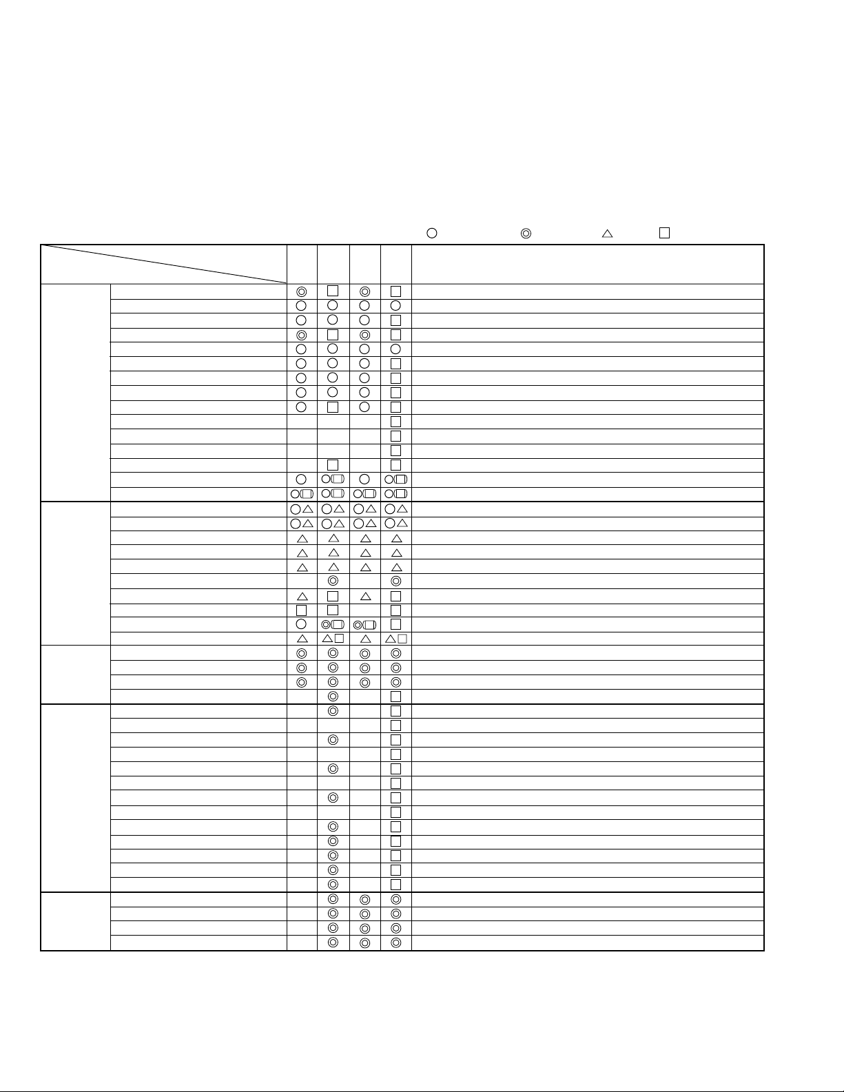
1-2. SERVICE TOOLS AND CLEANING
1-2-1. SERVICE TOOLS
NOTES ON ALIGNMENT TAPES
Select a PAL or NTSC alignment tape from the list below, according to the transmission system of the VCR you are
repairing.
PAL: For models with 625 scanning lines and a field frequency of 50Hz
NTSC: For models with 525 scanning lines and a field frequency of 60Hz
No. Tool Tool No. Remarks
NTSC PAL
1 Alignment tape VHJ-0005 VHJ-0008 SP colour bar 1kHz (normal)
2 Alignment tape VHJ-0006 VHJ-0009 SP monoscope 7kHz or 6kHz (normal)
3 Alignment tape VHJ-0007 ——— EP monoscope No Audio signal
4 Alignment tape ——— VHJ-0052 LP monoscope 3kHz (normal)
5 Alignment tape VSJ-1001 ——— EP Sync signal 3kHz (normal)
6 Eccentric screw driver VHJ-0003 Used to adjust the tape path
7 Nut box VHJ-0048 Used to adjust the height of the lever
load assembly
8 Torque dial gauge VHJ-0004 Used to measure reel winding torque
9 Cassette torque meter VHJ-0016 Used to measure back tension torque
10 Load lever assembly height adjustment tool VHJ-0111 Used to adjust the height of the load
lever assembly
11 Torque gauge screwdriver VHJ-0014 Used to adjust the tightening torque
of screws
12 3 mm dia. bit for torque screwdriver VHJ-0045 Used to replace the bit of the torque
gauge screwdriver
13 Oil VHJ-0099
14 Grease VHJ-0100
15 Grease VHJ-0101
16 Grease VHJ-0114
17 Upper drum fitting tool kit (includes VHJ-0113) VHJ-0112 Used to reassemble the upper cylinder
18 Hexagonal wrench VHJ-0113 Spare hexagonal wrench for upper
drum fitting tool kit
VHJ-0005,VHJ-0006,VHJ-0007,
VHJ-0008,VHJ-0009,VHJ-0052,
VSJ-1001
No. 1, 2, 3, 4, 5
VHJ-0016
No.9
VHJ-0099
No. 13
VHJ-0003
No. 6
VHJ-0111
No. 10
VHJ-0100, VHJ-0101, VHJ-0114
No. 14, 15, 16
VHJ-0048
VHJ-0014
VHJ-0112
and
No. 7
No. 11
VHJ-0113
No. 17, 18
VHJ-0004
No. 8
VHJ-0045
No. 12
Fig.1-2-1
–3–
Page 4
1-2-2. CLEANING
1. Cylinder (Drum) (See Fig.1-2-2)
Moisten a chamois with methyl alcohol and clean the
video head and the tape path surface of the cylinder. Be
sure to wipe horizontally in relation to the video head. If
you wipe vertically, or use excessive force, you can
damage the video head.
2. Tape Path System / Reel Drive System
Clean the pinch roller, the capstan shaft, the tape guides,
the FE head, the ACE head, the reel table, the pulley and
the reel belt with a soft cloth, or chamois, moistened with
methyl alcohol.
Cylinder (Drum)
NOTE: If the dirt on the tape guide cannot be cleaned off,
replace the tape guide.
2. AN OVERVIEW OF THE MECHANISM
2-1. NAMES OF THE MAIN PARTS
2-1-1. CASSETTE MECHANISM ASSEMBLY
Special washer
Washer
Stand L
Tray lock
spring
Tape path surface Video head
Fig.1-2-2
Release lever
Lid opener spring
Under frame
Door opener
lever
–4–
Drive gear
Pinion gear
Lock gear
Gear holder
Fig. 2-1-1
Page 5
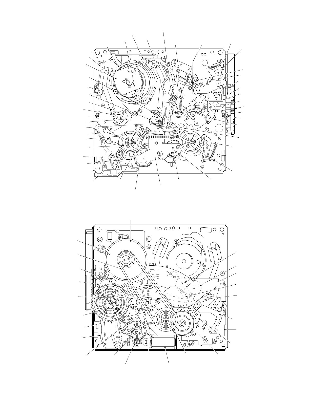
2-1-2. TOPVIEW
Cylinder mounting
Guide roller assembly
Full erase head
T incline mounting assembly
S incline mounting assembly
Guide roller assembly
Tape end sensor
BT lever assembly
Tape sensor LED
Band brake assembly
Supply reel assembly
S soft lever
Stator
BT spring
EP switch
Cleaner roller assembly
Cylinder (Drum)
Rotor
Capstan brake assembly
Cleaner lever
Audio R/P head
assembly
(ACE head)
Stopper lever
assembly
Dew sensor
Pinch roller lever assembly
Capstan motor
Pinch lift cam
Pinch lift mounting
Front rack gear
Opener mounting
Pinch cam gear
Start rack gear
Load lever assembly
Tape top sensor
L guide act lever assembly
T brake assembly
T soft brake assembly
Take up reel assembly
2-1-3. UNDERSIDE
Capstan mounting
Reel belt
Pinch cam gear
OPT pinch relay gear
Brake control lever
Main cam
Clutch change lever
Crescent slide
EP sw lever
assembly
S reel gear
Capstan motor
T reel gearT brake act slideS brake
Clutch mounting assembly
Fig. 2-1-2
T load gear
S load gear
Crescent mounting
T load lever assembly
S load lever assembly
BT spring lever assembly
MC-1 PWB assembly
S brake act slide
Wheel gear 1Wheel gear 2
assembly
Loading motor assemblyWorm gear assembly
Reel pulleyBrake act lever
Friction gear assembly
Fig. 2-1-3
–5–
Page 6
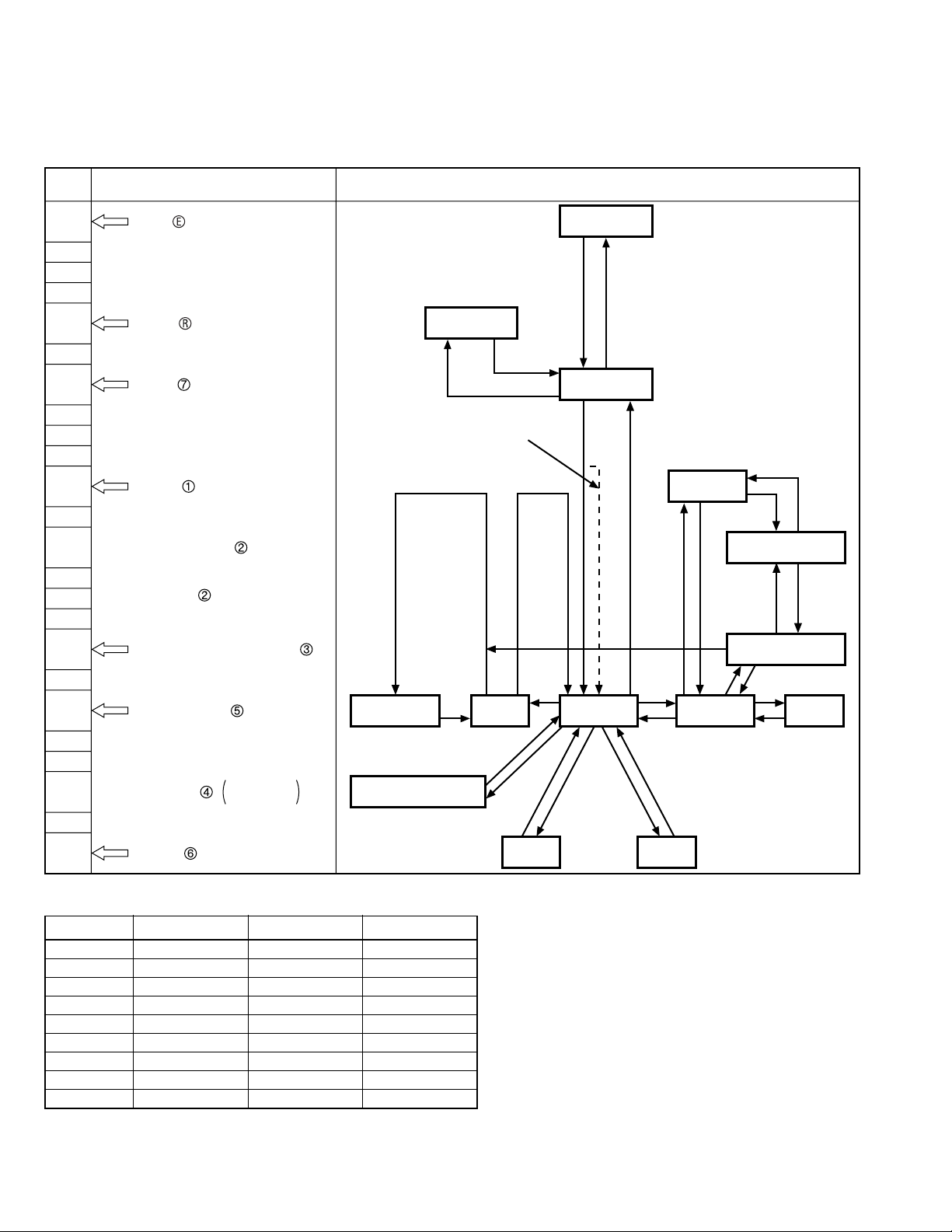
2-2. AN OVERVIEW OF THE MECHANISM MODES
2-2-1. MECHANISM MODE SWITCHING TABLE
NOTE: The letters and figures enclosed in circles in the mechanism mode column are the codes on the crescent slide.
HEX
DATA
6
4
0
6
2
0
7
0
1
0
1
0
2
0
2
0
Mechanism mode The principal mode-switching states of the mechanism
EJECT
Distinguished by whether the
EP switch is ON or OFF.
Horizontal shift section.
Vertical shift section.
IN REW
INITIAL
Cleaner roller assembly: ON
S/T mounting incline assembly
pressure begins.
S/T mounting incline assembly
pressure ends.
REVIEW
R. STILL/R. SLOW
IDLER POS.
(Pinch roller OFF)
IN REW
(SHORT REW)
When loading is carried out starting
at the CASSETTE IN position
CASSETTE OUT
(EJECT)
INITIAL
REVIEW
R. STILL/R. SLOW
3
STILL/SLOW/REC (INTERVAL)
0
5
PLAY/STOP/REC
REC PAUSE
0
6
4
BRAKE pos.
POWER OFF
STAND BY
STAND BY/POWER OFF
0
6
FF/REW
MODE SWITCH OUTPUT TABLE
HEX DATA SW DATA 2 SW DATA 1 SW DATA 0
0H H H
1H H L
2H L H
2H L H
3H L L
4L H H
5L H L
6L L H
7L L L
STILL/SLOW/REC
STOP PLAY CUEREC
REW FF
H: 5V
L: 0V
Low active
Fig.2-2-1
–6–
Page 7
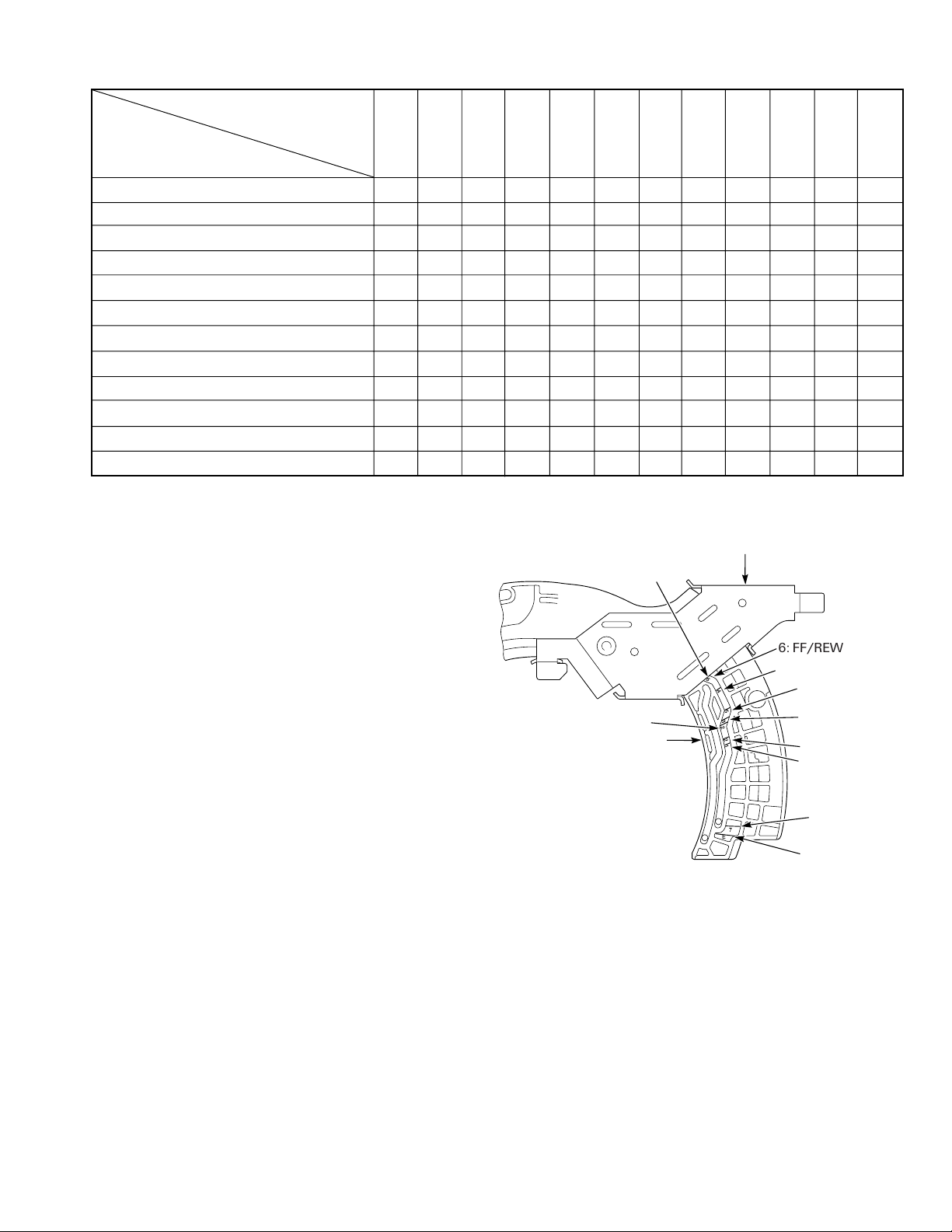
2-2-2. MOVEMENT CHECK LIST FOR THE MAIN PARTS OF THE MECHANISM
Mechanism mode
REV
Principal parts
T brake assembly
S brake assembly
T soft brake assembly
S soft lever
BT lever assembly
BT spring
Pinch roller lever assembly
Clutch mounting assembly
Load lever assembly
Capstan brake assembly
S and T incline mounting assembly
Cleaner roller assembly
EJECT
OFF
OFF
OFF
ON
OFF
OFF
UP
PLAY
UNLO
OFF
OFF
OFF
OFF
OFF
ON
OFF
OFF
UP
PLAY
UNLO
OFF
OFF
IN REW
ON
OFF
OFF
ON
OFF
OFF
UP
PLAY
UNLO
OFF
OFF
INITIAL
ON
OFF
ON
ON
OFF
OFF
UP/
DOWN
PLAY
LO
OFF
LO
(ON)
(LOADING)
(UNLOADING)
ON
OFF
ON
ON
OFF
OFF
DOWN/
UP
PLAY
LO
OFF
UNLO
(ON)
OFF
OFF
ON
OFF
ON
ON(W)
ON
PLAY
LO
OFF
OFF
IDLER
OFF
OFF
ON
OFF
ON
ON(W)
OFF
PLAY
LO
OFF
OFF
2-2-3.HOW TO CHECK THE MECHANISM MODE
POSITION
You can tell which mode the mechanism is currently in by
looking at the codes and marking-lines on the crescent
slide on the underside of the mechanism chassis. The
edge of the crescent mounting is used as the reference
line, as shown in Fig.2-2-2, and the marking-lines and
symbols indicating the mechanism modes are displayed
on the crescent slide, which slides against the edge of the
crescent mounting. The mechanism mode is read off
from the marking-line on the slide crescent which is
aligned with the reference-line on the crescent mounting.
Example: In Fig.2-2-2, marking-line 6 is aligned with the
reference-line on the crescent mounting, so the mechanism is seen to be in FF/REW mode.
crescent mounting
is the reference-line.
2: R.STILL/R.SLOW
Crescent slide
(S): Strength (W): Weakness
BRAKE
STILL/SLOW
OFF
OFF
OFF
OFF
ON
ON(S)
ON(S)
ON
PLAY
PLAY
LO
ON
OFF
PLAY/STOP
OFF
OFF
OFF
OFF
ON
ON
LO
OFF
OFF
(POWER OFF)
ON
ON/OFF
ON/OFF
ON
OFF
OFF
ON
ON(S)
ON(W)
OFF
PLAY
LO
OFF
OFF
OFF
OFF
ON
OFF
FF
LO
OFF
OFF
Crescent mountingThe edge of the
6: FF/REW
6
4
5
3
2
2
1
4: BRAKE (POWER OFF)
5: PLAY/STOP/
REC
3: STILL/SLOW/
REC (INTERVAL)
2: IDLER
1: REVIEW
R.STILL/
FF/REW
OFF
OFF
ON
OFF
ON
OFF
ON
PLAY
LO
ON
OFF
R.SLOW
2-2-4. SELF-DIAGNOSIS DISPLAY
Some models are equipped with the SELF-DIAGNOSIS
DISPLAYS function.
Use it as a means of finding out the symptoms and cause
of the error before performing repairs.
For details, refer to the separate service manual for the
respective models.
–7–
7
E
7: INITIAL
E: EJECT
Fig.2-2-2
Page 8
3. DISASSEMBLING THE MAIN PARTS OF THE MECHANISM
POINTS TO NOTE
• When fitting the parts of the mechanism, refer to the
"Assembly Notes", and proceed in the reverse of disassembly order.
• Dis-assembly and assembly should be carried out in
EJECT mode unless a movement mode is explicitly
specified. EJECT mode is the state in which the cassette tape has been ejected.
• Clamps are used to prevent parts coming loose. When
removing a clamp, be careful not to force it, as this can
result in damage.
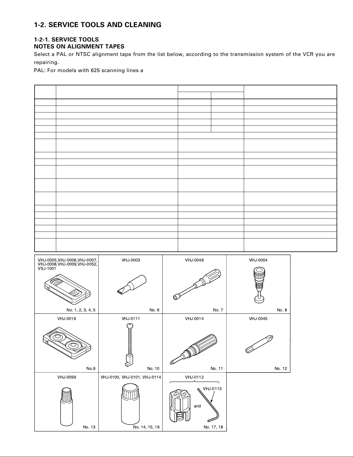
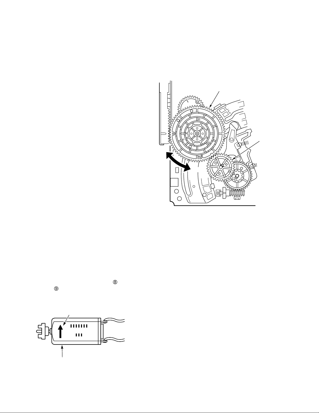
3-1. HOW TO MAKE THE MECHANISM
MOVE
In order to check a movement such as front loading, front
unloading, tape loading, tape unloading, raising/lowering and pressing the pinch roller, you will need to operate
the loading motor. There are two methods of operating
the loading motor, and these are explained in sections 31-1. The above movements can also be performed without operating the loading motor, by following the method
explained in section 3-1-2.
3-1-2.MAKING THE MECHANISM MOVE USING
THE MANUAL METHOD
1) Refer to section 3-2 and remove the mechanism unit.
2) Refer to section 3-15 and remove the wheel gear 2.
3) If you turn the main cam counterclockwise, the mechanism will switch to a mode such as PLAY or FF/REW.
To switch from FF/REW mode to EJECT mode, turn
the main cam clockwise.
Main cam
Wheel gear 2
CW
CCW
3-1-1.OPERATING THE LOADING MOTOR BY THE
MANUAL METHOD (See Fig.3-1-1)
1) Refer to section 3-2 and install the mechanism unit.
2) Using your finger, turn the loading motor located at
the rear of the mechanism unit. For EJECT, turn the
loading motor in the direction of the arrow on the
loading motor. For PLAY or FF/REW, turn it in the
opposite direction.
When rotating the loading motor in the EJECT direction with a tape slacken, stop the rotation of the
loading motor before beginning front unloading.
Rotate the capstan motor with your hand, wind the
slacked part of the tape, and rotate the loading motor
in the EJECT direction again.
When carrying out front loading, release the lock
by pressing down the tray lock lever
opener lever
(shown in Fig.3-2-2).
The arrow which show the direction of EJECT
of the cassette mechanism assembly
and the lid
Fig.3-1-2
Loading motor
Fig.3-1-1
–8–
Page 9
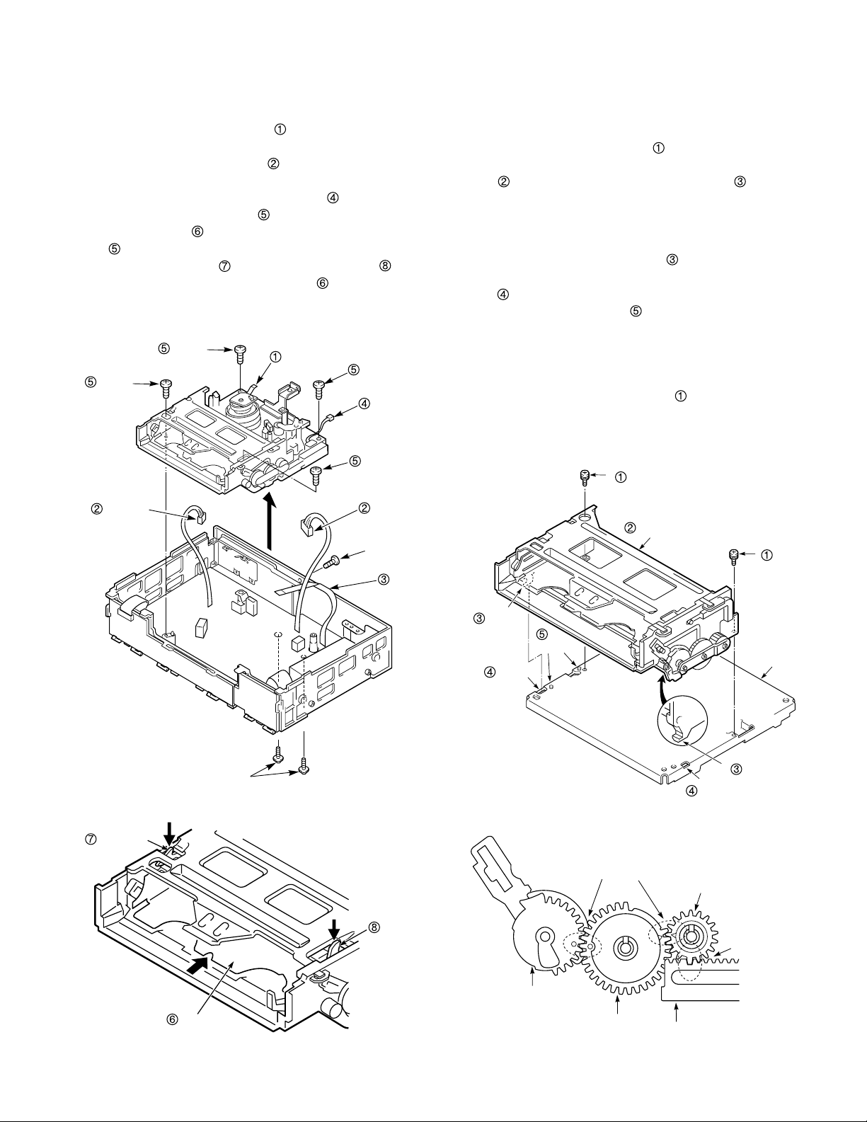
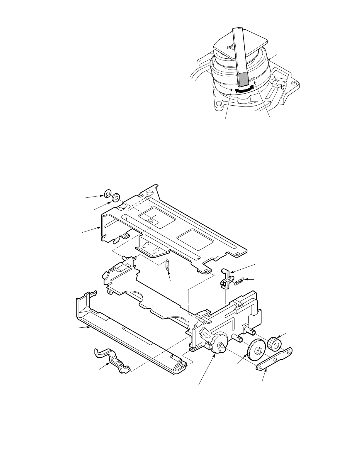
3-2. MECHANISM UNIT
(See Figs. 3-2-1 and 3-2-2)
1) Remove the top cover, bottom cover and front cabinet assembly.
2) Unplug the flat cable
assembly on the cylinder (drum), and unplug the
ACE/FE head connectors
3) Unplug the flat cable from the stator.
4) Unplug the dew sensor connector
5) Remove the four screws
unit. The tray
on the front, so release the lock by pressing down
the tray lock lever
in Fig.3-2-2, then slide off the tray
referring to section 3-1 and turn the loading motor in
the PLAY direction.
Screw
will stop you removing the two screws
and the lid opener lever shown
Screw
from the CP-1 PWB
.
.
, then lift up the mechanism
. Move the tray by
Flat cable
Screw
Dew sensor
connector
Screw
3-3. CASSETTE DRIVE MECHANISM
3-3-1.CASSETTE MECHANISM ASSEMBLY
(See Figs.3-3-1 and 3-3-2)
1) Put the VCR into EJECT mode.
2) Remove the two screws
3) Lift up the back of the cassette mechanism assembly
slightly, and remove the two hooks on the front.
ASSEMBLY NOTES:
1. The cassette mechanism assembly and the mecha-
nism chassis should both be fitted in EJECT mode.
2. Check that the two hooks
mechanism chassis, and make sure that the two holes
in the cassette mechanism assembly are aligned
with the two dowels
3. Make sure that the big tooth on the pinion gear of
the cassette mechanism assembly slots properly into
the deepest gap in the start rack gear, as shown in
Fig.3-3-2.
4. When fitting the two screws
screwdriver (VHJ-0014). Give the screws a tightening
torque of 5 kg/cm.
.
have snapped into the
on the mechanism chassis.
, use the torque gauge
Screws
FE head
connector
Tray lock
lever
ACE head
connector
Flat cable
Fig.3-2-1
Hook
Hole
Dowel
Cassette mechanism assembly
Screws
Mechanism
chassis
Hook
Hole
Fig.3-3-1
Ensure correct
interlocking
Pinion gear
Tray
Lid opener
lever
Fig.3-2-2
–9–
Drive gear
Lock gear
Ensure correct
interlocking
Start rack gear
Fig.3-3-2
Page 10
3-3-2. CASSETTE DRIVE GEAR (See Fig.3-3-3)
1) Refer to section 3-3-1 and remove the cassette mechanism assembly.
2) Remove clamps
holder
3) Remove the clamp
4) Remove the clamp
.
and , then remove the gear
, then remove the pinion gear .
, then remove the lock gear .
ASSEMBLY NOTES:
1. Put the tray in the EJECT mode position before fitting
any parts.
2. Apply grease (VHJ-0100) to the gear mounting shafts,
all the gear teeth, and the cam part of the drive gear
.
3. Ensure that the drive gear, the lock gear and the
pinion gear interlock correctly, as shown in Fig.3-3-2.
4. Make sure the clamps
holder
Tray
.
and snap in to the gear
Apply
grease
Pinion gear
(grease the
outer rim of
Clamp
the teeth)
3-3-3.DOOR OPENER, UNDER FRAME AND
STAND L (See Fig.3-3-4)
1) Remove the cassette mechanism assembly, referring
to section 3-1.
2) Remove the two clamps
frame
3) Press down the tray lock lever
lever
you. In this state, press the clamp
door opener lever
4) Remove the special washer
washer
5) Remove the two clamps
Be careful not to exert too much force on the clamps
, pulling it towards you.
, and loosen the tray , lifting it away from
.
.
, as this could cause damage.
and take out the under
and the lid opener
and remove the
, then remove the
and take out the stand L .
ASSEMBLY NOTES:
1. Apply grease (VHJ-0100) to the grooves on the
stand L, the inside of the hole
and the mounting hole
the stand R.
2. Before fitting the stand L
tray
back as far as the EJECT mode position. Put
the two pins
the stand L. Put the drive shaft
3. Be sure to fasten the two clamps
on the stand R, and to fasten the two clamps on
the stand L.
on the tray into the grooves on
in the door opener lever of
in the drive shaft ,
, be sure to move the
into the hole .
and the clamp
Drive gear
Clamp
Lock gear
(grease the outer rim
of the teeth)
Gear holder
Special
washer
Fig.3-3-3
Washer
Grooves
Hole
Clamp
Drive
shaft
Door opener
lever
Under frame
Stand L
Pins
Clamp
Tray
lock lever
Tray
Clamp
Lid opener
lever
Clamps
Stand R
Hole
Fig.3-3-4
–10–
Page 11

Shaft
Mounting
Plastic spring
Clamp
Cleaner lever
Clamp
Cleaner roller assembly
Plastic spring
3-3-4.START RACK GEAR AND FRONT RACK GEAR
(See Figs.3-3-5 and 3-3-6)
1) Remove the mechanism unit, referring to section 3-2.
2) Remove the cassette mechanism assembly, referring
to section 3-3-1.
3) Remove the special screw
the front rack gear assembly
it stops, then take it off the shaft
damage the shaft
4) Remove the spring
5) Remove the clamp
remove the start rack gear
.
. When you do this, slide
towards the front until
. Take care not to
.
on the front rack gear , then
.
ASSEMBLY NOTES:
1. Apply grease (VHJ-0100) to the front rack gear and
all over the inside of the groove on the start rack
gear
2. Align the positioning mark
with the mark on the main cam .
3. When installing the cassette mechanism assembly,
refer to section 3-3-1 and align the start rack gear with
the pinion gear.
.
Clamp
on the front rack gear
Front rack gear
(apply grease to
inside of groove)
Shaft
Front rack
gear assembly
3-4. CLEANER ROLLER ASSEMBLY
(See Fig.3-4-1)
1) Remove the clamp and take out the cleaner lever
. When you do this, be careful not to bend the
plastic springs
2) Remove the clamp
assembly
the cleaner roller assembly
ASSEMBLY NOTES:
1. When mounting the cleaner lever on the shaft ,
press the clamp
arrow, and snap it into the mounting
R/P head assembly.
and on the cleaner lever .
, and take out the cleaner roller
. Be careful not to touch the sponge on
.
in the direction shown by the
on the audio
Positioning mark
Main cam
Start rack gear
(apply grease to
inside of groove)
Positioning mark
Spring
Fig.3-4-1
Special screw
FIg.3-3-5
Front rack gear
Fig.3-3-6
–11–
Page 12

3-5. CYLINDER (DRUM)
(See Fig. 3-5-1 to 3-5-3)
3-5-1.CYLINDER (DRUM) MOTOR,
UPPER CYLINDER ASSEMBLY
1) Disconnect the flexible cable connected to the
stator
2) Remove the two screws
and spring
In this state, the cylinder earth chip
top and bottom of the mechanism unit are reversed.
Note: Cylinder earth chip
3) Remove the two screws
4) Loosen the screw
remove the cylinder motor mounting
Note: The hexagonal wrench (VHJ-0113) is 2mm
5) Remove the upper cylinder assembly
The spacer
cylinder assembly
.
, and remove the stator ,
.
will fall off if the
can be removed by
removing the cylinder motor mounting
step 4).
and remove the rotor .
with the hexagonal wrench, and
.
diagonally. It is provided with the servicing
tool upper drum fitting tool kit (VHJ-0112).
and the spacer
.
may come off attached to the upper
.
in
Screws
Screws
Spring
Cylinder earth chip
Flexible cable
Stator
Rotor
Cylinder motor mounting
Screw
Upper cylinder
assembly
Spacer
ASSEMBLY NOTES:
1. Adjustments are required when attaching the cylinder
motor mounting
protruded side of the cylinder motor mounting
downwards, and with the hexagonal wrench pressed
to screw
mounting
, adjust the position of the cylinder motor
in the direction of the screw . In this
state, hold the cylinder motor mounting
upper drum fitting tool (VHJ-0112) and tighten the
screw
with the hexagonal wrench.
2. When attaching the rotor
adjusted to that of the upper cylinder assembly
shown in Fig. 3-5-3, attach so that the hole
upper cylinder assembly
are on the same side.
3. Tighten the two screws
and the two screws for attaching the stator using
a torque of 2.5 to 3.5 kg/cm.
4. Be careful that the tape path surface of the cylinder
(drum) does not scratch or become dirty.
If it becomes dirt, clean.
5. After attaching, refer to "4-3. Tape path adjustment"
and the section on electrical adjustments in the service
manuals for the respective models, and adjust the
switching position of the servo circuit.
. As shown in Fig. 3-5-2, face the
with the
, the phase must be
. As
of the
and hole of the rotor
for attaching the rotor
Upper drum
fitting tool
(VHJ-0112)
Mounting
motor
cylinder
Screw
Upper cylinder
assembly
Screw
Hexagonal
wrench
Hole
Fig.3-5-1
Fig.3-5-2
–12–
Rotor
Hole
Fig.3-5-3
Page 13

3-5-2. CYLINDER MOUNTING
(See Figs. 3-5-4 and 3-5-5)
1) Put the mechanism into EJECT mode.
2) Refer to section 3-4 and remove the cleaner lever.
3) Disconnect the flexible cable connected to the
stator
4) Disconnect the flexible cable connected to the
connector
5) Remove the three screws
or soil the tape path surface of the cylinder (drum), lift
the cylinder mounting
raised. (See Fig. 3-5-4)
Screws
.
.
. Taking care not to scratch
slightly, and keeping it
Stator
Screw
ASSEMBLY NOTES:
1. Align the cylinder assembly with the two dowels
on the cylinder mounting . (See Fig. 3-5-5)
2. Apply grease (VHJ-0100) to the rails of the cylinder
mounting
with the S and T incline mounting assembly). (See
Fig. 3-5-5)
3. Align the two dowels
with the two holes on the mechanism chassis. (See
Fig. 3-5-4)
4. After assembly, clean the tape path surface of the
cylinder (drum).
5. After replacing the cylinder mounting or the cylinder
assembly, do the tape path adjustment as instructed
in section 4-3, and do the switching position
adjustment of the servo circuit.
(grease the parts which come in contact
on the cylinder mounting
Rails
Rails
Holes
6) Remove the three screws
cylinder mounting
. (See Fig. 3-5-5)
Cylinder mounting
Dowels
Connector on the
CP-1 PWB assembly
Fig.3-5-4
at the bottom of the
Dowels
Cylinder assembly
Cylinder mounting
Screws
Fig.3-5-5
–13–
Page 14

3-6. FE HEAD AND ACE HEAD
3-6-1.AUDIO R/P HEAD ASSEMBLY (ACE HEAD)
(See Fig.3-6-1)
1) Unplug the connector from the audio R/P head
assembly (ACE head).
2) Remove the two screws
P head assembly (ACE head)
ASSEMBLY NOTES:
1. Align the hole on the audio R/P head assembly
(ACE head) with the pin
2. After assembly, check that the clamp
roller assembly has snapped into the mounting of
the audio R/P head assembly (ACE head)
3. After assembly, clean the surface of the head with a
soft cloth or chamois.
4. After assembly, refer to section 4-3, and adjust the
head height, the azimuth and the tracking (X) position.
, then remove the audio R/
and the washer .
on the chassis unit.
on the cleaner
.
3-6-2. FULL ERASE HEAD (See Fig.3-6-2)
1) Unplug the connector from the full erase head .
2) Remove the screw
and the full erase head .
ASSEMBLY NOTE:
1. After assembly, clean the full erase head .
Screw
Full erase head
Screws
Audio R/P head assembly
(ACE head)
Hole
Fig.3-6-2
Washer
Pin
Clamp
Fig.3-6-1
–14–
Page 15

3-7. CAPSTAN MOTOR
3-7-1. CAPSTAN MOTOR
[Case 1. High speed FF/REW model] (See Fig. 3-7-1)
1) Refer to section 3-2, then remove the mechanism
unit.
2) Remove the reel belt
3) Remove the three screws
.
4) Remove the heat transfer spacer
motor or mechanism chassis.
ASSEMBLY NOTES:
1. Check that connector is inserted in the CP-1 PWB
assembly.
2. When fitting the three screws
gauge screwdriver (VHJ-0014). Give the screws a
tightening torque of 3.5 kg/cm.
3. After assembly, clean the capstan shaft with a soft
cloth or chamois.
Screws
.
and the capstan motor
from the capstan
, use the torque
ASSEMBLY NOTES:
1. Check that connector is inserted in the CP-1 PWB
assembly.
2. When fitting the three screws
gauge screwdriver (VHJ-0014). Give the screws a
tightening torque of 3.5 kg/cm.
3. After assembly, clean the capstan shaft with a soft
cloth or chamois.
Screws
Connector
, use the torque
Capstan
motor
Heat transfer
spacer
Capstan
motor
Connector
Reel belt
Fig. 3-7-1
[Case 2. Normal FF/REW model] (See Fig. 3-7-2)
1) Refer to section 3-2, then remove the mechanism
unit.
2) Remove the screw
ing
.
3) Remove the reel belt
4) Remove the three screws
.
, then remove the capstan mount-
.
and the capstan motor
Capstan
mounting
Reel belt
3-7-2. CAPSTAN BRAKE ASSEMBLY
(See Fig.3-7-3)
1) Remove the spring .
2) Remove the clamp
assembly
.
Capstan brake
assembly
Clamp
, then remove the capstan brake
Spring
Screw
Fig. 3-7-2
–15–
Fig.3-7-3
Page 16

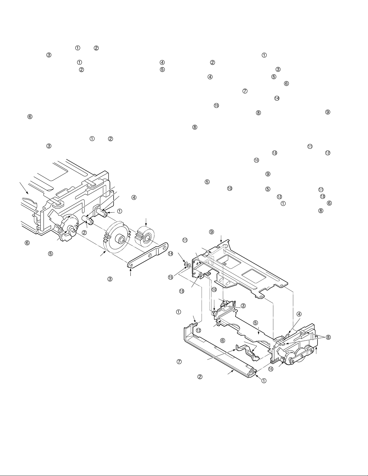
3-8. LOADING MOTOR ASSEMBLY AND
WORM GEAR ASSEMBLY
(See Fig.3-8-1)
1) Refer to section 3-2 and remove the mechanism unit.
2) Remove the soldering on the lead wires
loading motor assembly
sembly. When you do this, be careful not to let the
soldering iron touch any other parts.
3) Press the clamp
assembly
exert too much force on the clamp
4) Remove the worm gear assembly
performance, do not dis-assemble the worm gear
assembly
.
, and remove the loading motor
and the damper . Be careful not to
from the MC-1 PWB as-
.
. To maintain
ASSEMBLY NOTES:
1. Apply grease (VHJ-0010) to the teeth of the worm
gear assembly
the hole of the worm gear assembly
2. Check that the clamps
loading motor assembly.
3. Check the polarity of the lead wires
wire is the positive terminal, and the gray wire is the
negative terminal). After soldering the lead wires
adjust them so that they do not touch the friction gear
assembly.
. Then apply grease (VHJ-0114) to in
.
and are securing the
of the
(the orange
3-9. PINCH ROLLER PRESSURE
MECHANISM
3-9-1.PINCH ROLLER LEVER ASSEMBLY
(See Fig.3-9-1)
1) Remove the clamp , then remove the pinch lift
mounting
2) Remove the spring
lever assembly
fore you do this, align the Indentation
roller lever assembly
lift mounting
ASSEMBLY NOTE:
1. Be careful to keep the surface of the pinch roller free
of dust and dirt.
,
.
, then remove the pinch roller
off the pinch lift mounting . Be-
with the clamp on the pinch
.
Pinch roller lever
assembly
Indentation
Spring
on the pinch
Apply
grease
(VHJ-0100)
Worm gear assembly
Damper
Apply
grease
(VHJ-0114)
Clamps
Loading motor assembly
Lead wires
Gray:
negative
Orange:
positive
Clamp
Fig.3-8-1
Pinch lift mounting
Clamp
Clamp
Fig.3-9-1
–16–
Page 17

3-9-2.PINCH LIFT CAM AND PINCH CAM GEAR
Arrow
Square mark
OPT pinch
relay gear
Pinch cam gear
Round hole
Pinch lift camIndentation
Positioning marks on
OPT pinch relay gear
Arrow on MC-1 PWB
assembly
(See Figs.3-9-2 and 3-9-3)
1) Refer to section 3-2 and remove the mechanism unit.
When you do this, make sure the mechanism is in
EJECT mode.
2) Refer to section 3-9-1 and remove the pinch roller
lever assembly.
3) After removing the screw
, then remove the opener mounting .
4) Remove the clamp
5) Remove the pinch cam gear
and the pinch lift cam .
, undo the three clamps
.
ASSEMBLY NOTES:
1. Apply grease (VHJ-0100) around the shaft , all over
the teeth
teeth of the pinch lift cam , all over the cam grooves
, and all over the “V Part ” of the opener mount-
ing . Apply grease (VHJ-0101) to the outside of the
shaft
gear .
2. Check that the positioning mark
pinch relay gear
MC-1 PWB assembly, as shown in Fig.3-9-3. Then
align the square mark
with the arrow on the MC-1 PWB assembly.
After that, align the round hole on the pinch lift cam
with the indentation on the pinch cam gear .
If you have carried out the above alignments and the
pinch roller will still not move up and down or perform the pressing movement correctly, refer to section 3-15 and check the alignment of the gear wheels
1 and 2, the main cam, and the OPT pinch relay gear.
of the pinch cam gear , all over the
and all over the top cam of the pinch cam
on the OPT
is aligned with the arrow on the
on the pinch cam gear
Fig.3-9-3
Opener
mounting
Clamps
Pinch cam gear
“V” part
Shaft
Shaft
Screw
Pinch lift cam
Clamp
Fig.3-9-2
–17–
Page 18

3-10. L GUIDE ACT LEVER ASSEMBLY,
LOAD LEVER ASSEMBLY AND
STOPPER LEVER ASSEMBLY
(See Fig.3-10-1)
1) Refer to section 3-3 and remove the cassette mechanism assembly.
2) Refer to sections 3-9-1 and 3-9-2 ,then remove the
pinch roller lever assembly and the opener mounting.
3) Remove the stopper spring
4) After removing the washer
spring
5) Remove the special nut
assembly
6) Remove the stopper lever assembly
and the L guide act lever assembly .
and the L guide lever spring .
ASSEMBLY NOTES:
1) Apply grease (VHJ-0100) to the toothed area of the
L guide act lever assembly
and .
2) Refer to section 4-3 and adjust the height of the load
lever assembly.
3) Hook the L guide lever spring
and the load lever assembly shown in Fig. A.
4) Put the pin
the cam groove
of the L guide act lever assembly into
of the crescent slide.
.
, remove the L guide act
, then remove the load lever
.
and around the shafts
into the stopper
3-11. BT LEVER ASSEMBLY
(See Fig.3-11-1)
1) Refer to section 3-2 and remove the mechanism unit.
2) Refer to section 3-3-1 and remove the cassette mechanism assembly.
3) Remove the BT spring
spring
4) Remove the clamp
nism chassis, then remove the BT lever assembly
5) Remove the clamp
Then, as shown in Fig. A, align the other end of the
band brake assembly with the protruding parts of the
BT lever assembly
on the underside of mechanism chassis.
ASSEMBLY NOTES:
1. When fitting the BT lever assembly , be careful not
to bend the stopper
assembly
2. Hook the long hook of the BT spring
lever assembly
4. After assembly, make sure that the mountings on
both ends of the band brake assembly
positioned as shown in Fig. C.
5. After assembly, refer to section 4-2-1, and make the
appropriate adjustment.
out of shape by knocking it against them.
, as shown in Fig. B.
, and remove the sub BT
on the underside of the mecha-
on the band brake assembly .
before removing it.
or the S incline mounting
into the BT
are
.
L guide
lever spring
L guide
act spring
L guide
act lever
assembly
Stopper
lever assembly
Cam
groove
Washer
Special nut
Shaft
L guide lever spring
Fig. A
Load lever
assembly
Stopper spring
Pin
Shaft
Stopper
Protruding
parts
BT
spring
Fig. D
Sub BT
spring
BT spring
lever
assembly
Fig. A
Fig. B
Clamp
Clamp
Band brake
assembly
BT lever
assembly
Fig. C
S incline
mounting
assembly
Stopper
Fig.3-11-1
Fig.3-10-1
–18–
Page 19

3-12. REEL DRIVE MECHANISM
S soft
spring
Shaft
S reel gear
Supply reel
assembly
Washer
Shaft
Clamp
S soft lever
Screws
3-12-1.REEL BELT, REEL PULLEY, FRICTION GEAR
ASSEMBLY AND CLUTCH CHANGE LEVER
(See Fig.3-12-1)
1) Refer to section 3-2 and remove the mechanism unit.
2) Remove the reel belt from the reel pulley .
3) Take off the washer
4) Take off the washer
assembly
5) Remove the clutch change spring
6) remove the clamp
mechanism chassis, then remove the clutch change
lever
.
.
and remove the reel pulley .
and remove the friction gear
.
gripping the top of the
ASSEMBLY NOTES:
1. After cleaning the shafts and , apply a drop of oil
(VHJ-0099) to each.
2. Be careful not to get any grease on the reel belt
Reel belt
Washer
Reel pulley
Clutch change
spring
Clutch change lever
Washer
Clamp
Friction gear
assembly
Part A
Hole
Shaft
.
Shaft
Hole
Clutch
mounting
assembly
Fig.3-12-2
3-12-3.S SOFT LEVER, SUPPLY REEL ASSEMBLY
AND S REEL GEAR (See Fig.3-12-3)
1) Remove the S soft spring .
2) Remove the clamp
3) Refer to section 3-12-2 and remove the clutch mounting assembly.
4) Refer to section 3-11 and remove the band brake
assembly, then remove the supply reel assembly
, washer and the S reel gear .
, then remove the S soft lever .
ASSEMBLY NOTES:
1. After cleaning the shafts and , apply a drop of oil
(VHJ-0099) to each.
2. After assembly, clean the side of the supply reel
assembly
.
Shaft
Shaft
Fig.3-12-1
3-12-2.CLUTCH MOUNTING ASSEMBLY
(See Fig.3-12-2)
1) Refer to section 3-3-1 and remove the cassette
mechanism assembly.
2) Refer to section 3-12-1 and remove the reel pulley.
3) Remove the two screws
mounting assembly .
ASSEMBLY NOTES:
1. Align the two holes with the shafts and . Be
careful not to press part A of the clutch mounting
assembly
2. After assembly, make sure that the clamp on the
clutch change lever has snapped into the chassis.
against the band brake assembly.
, then remove the clutch
Fig.3-12-3
–19–
Page 20

3-12-4.T SOFT BRAKE ASSEMBLY, TAKE UP REEL
ASSEMBLY, T REEL GEAR (See Fig.3-12-4)
1) Remove the T soft spring .
2) Remove the clamp
assembly
3) Refer to section 3-12-2 and remove the clutch mounting assembly.
4) Pressing the T brake assembly
the arrow, remove the take up reel assembly
washer
.
and the T reel gear .
, then remove the T soft brake
in the direction of
ASSEMBLY NOTE:
1. After cleaning the shafts and , apply a drop of oil
(VHJ-0099) to each.
T reel gear
T brake
assembly
Take up reel
assembly
Washer
T soft brake
assembly
T soft spring
Clamp
3-13. BRAKES
3-13-1.S BRAKE ASSEMBLY, T BRAKE
ASSEMBLY, T BRAKE ACT SLIDE
(See Fig.3-13-1)
1) Refer to section 3-3-1 and remove the cassette mechanism assembly.
2) Remove the two clamps
,
brake act slide
assembly
moving the T brake act slide
3) Remove the brake spring
4) Remove the two clamps
remove the T brake assembly .
5) Remove the clamp
assembly
. (Note: You can remove the S brake
and the T brake assembly without re-
.
ASSEMBLY NOTES:
1. Apply grease (VHJ-0100) to the shafts and .
2. When fitting the T brake act slide , align the mark
with the shaft .
Brake spring
Clamp
, then remove the T
.)
.
simultaneously, then
, then remove the S brake
T brake act slide
Mark
Shaft
Shaft
Fig.3-12-4
Clamp
T brake
assembly
S brake
assembly
Clamp
Shaft
Shaft
Shaft
Clamps
Fig.3-13-1
–20–
Page 21

3-13-2.BRAKE CONTROL LEVER AND BRAKE ACT
LEVER ASSEMBLY (See Fig.3-13-2)
1) Refer to section 3-2 and remove the mechanism unit.
2) Refer to section 3-15 and remove the wheel gear 2.
3) Refer to sections 3-12-1, then remove the reel belt and
the reel pulley.
4) Remove the clamp
.
5) Remove the clutch change spring
6) Remove the clamps
control lever
of the mechanism chassis.
7) Remove the brake return spring
8) Refer to section 3-8 and remove the worm gear
assembly.
9) Remove the clamp
brake act lever assembly
ance of the brake act lever assembly
semble it.
, then remove the wheel gear 1
.
and , then remove the brake
. Remove the clamp on the topside
.
and clamp , then remove the
. To maintain the perform-
, do not disas-
ASSEMBLY NOTES:
1. Apply grease (VHJ-0100) to the shafts and , to the
teeth of the wheel gear 1
brake control lever
2. Put the pin
cam groove
3. Before fitting the wheel gear 1
with the hole on the mechanism chassis.
4. Refer to section 3-15 and align the wheel gear 2.
of the brake control lever into the
of the crescent slide.
, and to the pin of the
.
, align the hole
Pin
3-13-3.S BRAKE ACT SLIDE AND BT SPRING
LEVER ASSEMBLY
(See Figs.3-13-3 and 3-13-4)
1) Refer to section 3-16 and remove the crescent slide.
2) Refer to section 3-12-1 and remove the friction gear
assembly.
3) Slide the S brake act slide
arrow , then remove it.
4) Refer to section 3-11 and remove the BT spring.
5) Remove the sub BT spring
6) Press the BT spring lever assembly
the pin
, then remove it.
in the direction of the
.
until it touches
ASSEMBLY NOTES:
1. Apply grease (VHJ-0100) to the shaft shown in Fig.
3-13-3, and to the BT spring lever assembly
the S brake act slide
2. After mounting the BT spring lever assembly
the Shaft
and press it until it touches the pin .
3. Make sure that the clamps
into the S brake act slide
the S brake act slide
mechanism chassis.
Arrow on
mechanism chassis
S brake act
slide
, hook the BT spring onto the clamp
shown in Fig.3-13-4.
, and have snapped
. Align the arrow on
with the arrow on the
BT spring
lever
assembly
and
on
Sub BT
spring
Brake control lever
Clamp
Wheel
gear 1
Shaft
Hole
Clamp
Hole
Clutch change spring
Brake act lever
assembly
Brake return spring
Clamp
Cam groove
Clamp
Shaft
Fig.3-13-2
–21–
Clamp
Clamp
Clamp
Apply
grease
S brake
act
slide
Apply grease
Arrow
Clamp
Shaft
Pin
Pin
Fig.3-13-3
Apply grease
BT spring
lever
assembly
Fig.3-13-4
Page 22

3-14. GUIDES
3-14-1. GUIDE ROLLER ASSEMBLY
(See Fig.3-14-1)
1) Unscrew the two screws . When you do this, be
careful not to damage the cylinder or the video head.
2) Remove the two guide roller assemblies
screwing them counterclockwise.
ASSEMBLY NOTES:
1. Tighten the two screws to a torque of 600 g/cm.
After tightening, apply a screw-locking glue.
2. After replacing the parts, be sure to clean the guide
roller and carry out tape path adjustment as described in section 4-3.
Screw
Guide roller
assembly
by un-
3-14-2.S AND T INCLINE MOUNTING
ASSEMBLIES (See Fig.3-14-2)
1) Refer to section 3-2 and remove the mechanism unit.
2) Refer to section 3-5-2 and remove the cylinder unit.
3) Refer to section 3-1 and rotate the loading motor in
the PLAY direction until tape loading is completed.
4) Shift the S incline mounting assembly
the direction of the arrow
S load lever assembly
5) Shift the T incline mounting assembly
the direction of the arrow
T load lever assembly
, then remove it from the
.
, then remove it from the
.
slightly, in
slightly, in
ASSEMBLY NOTES:
1. Apply grease (VHJ-0100) to the rail (top, underside
and sides) on the mechanism chassis.
2. When fitting the S and T incline mounting assemblies
manually in the EJECT direction. When tape unloading begins, watch out in case the S and T incline
mounting assemblies
3. After replacing the parts, clean the cylinder and the
roller guide, then adjust the tape path as described in
section 4-3.
and into the rail, turn the loading motor
and get caught in the rail.
Guide roller
assembly
Screw
Fig.3-14-1
S incline mounting
assembly
S load lever
assembly
Apply grease to the
top, underside and
sides of the rail.
T incline
mounting
assembly
T load lever
assembly
Fig.3-14-2
–22–
Page 23

3-15. WHEEL GEAR 2, MAIN CAM AND
Clamp
Shaft
OPT pinch relay gear
Wheel gear 1
Front rack
gear
Main cam
Clamp
Shaft
Shaft
Pinch cam
gear
Crescent
slide
Wheel
gear 2
Washer
6
5
4
3
2
1
Fig. A
Align at
White line on the
MC-1 PWB assembly.
OPT pinch relay gear
Wheel gear 1
Front rack
gear
Main cam
Pinch cam
gear
Crescent
slide
Wheel gear 2
Align the hole in the
main cam with the
shaft of the OPT pinch
relay gear .
OPT PINCH RELAY GEAR
(See Figs.3-15-1 and 3-15-2)
1) Refer to section 3-2 and remove the mechanism unit.
When you do this, make sure the mechanism is in
EJECT mode.
2) Remove the clamp
.
3) Remove the washer
4) Remove the clamp
relay gear
.
ASSEMBLY NOTES:
1. Apply grease (VHJ-0100) to the shafts , and , to
the teeth of the main cam
cam groove of main cam
2. When fitting the OPT pinch relay gear
order as shown in Fig.3-15-2. The alignment of the
part
is shown in Fig. A. Position the teeth of the OPT
pinch relay gear
part
pinch cam gear
section 3-9-2 and check the positioning of the OPT
pinch relay gear, the pinch cam gear and the pinch lift
cam.
3. Align the hole in the crescent slide
the mechanism chassis, as shown at point
Fig.3-15-2 (refer to section 3-16 and see the
holes
4. When fitting the main cam
relay gear
points
5. When fitting the gear wheel 2
cam
respectively in Fig.3-15-2.
is aligned with the triangular mark on the
and in Fig.3-16-1).
and the front rack gear as shown at
and respectively in Fig.3-15-2.
and the wheel gear 1 as shown at points and
, then remove the wheel gear 2
, then remove the main cam .
, then remove the OPT pinch
, and to the all over the
.
, align it in
so that the sixth tooth space left of
. After aligning part , refer to
with the hole in
in
, position the OPT pinch
, position the main
Fig.3-15-1
Fig.3-15-2
–23–
Page 24

3-16. CRESCENT SLIDE
(See Figs.3-16-1 and 3-16-2)
1) Refer to section 3-2 and remove the mechanism unit.
When you do this, make sure the mechanism is in
EJECT mode.
2) Refer to section 3-3-1 and remove the cassette mechanism assembly.
3) Refer to section 3-7-2 and remove the capstan brake
assembly.
4) Refer to section 3-12-4 and remove the T soft brake
assembly.
5) Refer to section 3-13-1 and remove the T brake act
slide.
6) Refer to section 3-12-1, then remove the reel belt and
the reel pulley.
7) Refer to section 3-15, then remove the wheel gear 2
and the main cam.
8) Refer to section 3-13-2, then remove the wheel gear 1
and the brake control lever.
9) Remove the two screws
mounting
10) Remove the clamps
crescent slide
the right until it comes away from the clamp
remove it.
.
slightly. Slide the crescent slide to
ASSEMBLY NOTES:
1. Apply grease (VHJ-0100) to the points , , and
in Fig.3-16-1, and to the crescent slide shown in
Fig.3-16-2.
2. Before fitting the crescent slide , refer to section 3-
13-3 and align the arrow on the S brake act slide with
the arrow on the mechanism chassis. Then refer to
Fig.3-17-3 and check that the S load gear and the T
load gear have completed tape unloading.
3. When assembling the parts, raise the right side of
the crescent slide
position, slot the left side into the clamp
align the hole
chassis. When you do this, check that the hole
aligned with the pin
assembly, and that the hole
pin
on the S brake act slide, before pressing the
crescent slide
and are engaged.
4. After assembly, check that each lever and each brake
is working properly.
with the hole in the mechanism
into place. Check that the clamps
, then remove the crescent
, then raise the right end of the
, then
slightly, and keeping it in this
, then
on the BT spring lever
is aligned with the
Screw
Crescent
Crescent slide
Hole
Clamp
Hole
Pin
Hole
Clamp
Apply grease to the areas shown in
• The places marked by dots should be greased
particularly generously.
Grease the
sides
Grease the teeth
is
mounting
Hole
Pin
Fig.3-16-1
Crescent
slide
Fig.3-16-2
–24–
Page 25

3-17. S LOAD GEAR, T LOAD GEAR,
S LOAD LEVER ASSEMBLY AND
T LOAD LEVER ASSEMBLY
(See Figs.3-17-1, 3-17-2 and 3-17-3)
1) Refer to section 3-16 and remove the crescent slide.
2) Refer to section 3-14-2 and remove the S and T incline
mounting assemblies.
3) Remove the clamp
the S load gear
lever assembly
damage the clamp
Again, be careful when you disassemble the components, as the S load spring
4) Remove the following components: the T load
gear
assembly
components, as the T load spring
, the T load spring , and the T load lever
. Be careful when you disassemble the
ASSEMBLY NOTES:
1. Apply grease (VHJ-0100) to the shafts , and parts
A shown in Fig.3-17-1. Then apply grease (VHJ-0100)
to the parts shown in Fig.3-17-2.
2. When fitting the S load gear
align them in the tape-loaded state, as shown in Fig.
A in Fig.3-17-3. Again, after completing tape-unloading on these gears, check that they are positioned as
shown in Fig. B in Fig.3-17-3, then refer to section 314-2 and fit the S and T incline mounting assemblies.
, then remove the components:
, the S load spring and the S load
. When you do this, be careful not to
, which can be damaged easily.
will spring out.
will spring out.
and the T load gear
(T side)
(S side)
Apply
grease here
Apply
grease inside
the hole
Apply grease to the gears
Apply
grease
here
Apply
grease here
Apply grease inside
the hole
Apply
grease here
Fig.3-17-2
T load lever
assembly
T load
spring
T load
gear
Parts A
(apply
grease here)
T
S load spring
Shaft
Shaft
S
S load lever
assembly
Clamp
S load
gear
Fig.3-17-1
Fig. A: When tape loading is complete
T load gear
Fig. B: When tape unloading is complete
T load gear S load gear
S load gear
–25–
Fig.3-17-3
Page 26

3-18. TAPE SENSORS, REEL SENSOR AND
EP SW LEVER
3-18-1 TAPE TOP SENSOR AND TAPE END
SENSOR (See Fig.3-18-1)
1) Refer to section 3-2 and remove the mechanism unit.
2) Refer to section 3-3-1 and remove the cassette
mechanism assembly.
3) Remove the soldering from the MC-1 PWB assembly,
then remove the photo diodes
. When removing the photo diode on the tape
top sensor side, refer to section 3-15 and remove the
main cam.
, and the LED
Photo diode
(reel sensor)
Cut
Mounting shaft for
take up reel assembly
ASSEMBLY NOTES:
1. Fit the photo diodes and so that their photoreceptors to face the LED
Align the cuts in the LED
Push the photo diodes
down as they will go, so that they do not protrude
above the top of their holders.
2. Do the soldering quickly.
Turn the photoreceptors to
face the LED
Photo
diode
(Tape end
sensor)
LED
Holders
, as shown in Fig.3-18-1.
and the holder .
, and the LED as far
Photo
diode
(Tape top
sensor)
Align the cuts
Holder
Holders
Protrusion
Fig.3-18-2
3-18-3.EP SWITCH LEVER (See Fig.3-18-3)
1) Refer to section 3-3-1 and remove the cassette mechanism assembly.
2) Remove the EP switch spring
3) Remove the clamp
lever
.
, then remove the EP switch
.
ASSEMBLY NOTES:
1. Apply grease (VHJ-0100) to the protrusion on the
back of the EP switch lever
2. After fitting the cassette mechanism assembly, check
that in EJECT mode, the EP switch lever
touch the EP switch
.
.
does not
EP switch spring
Front
Fig.3-18-1
3-18-2. REEL SENSOR (See Fig.3-18-2)
1) Refer to sections 3-12-2 and 3-12-4, then remove the
clutch mounting assembly, the T soft brake assembly
and the take up reel assembly.
2) Refer to section 3-13-2, then remove the wheel gear 2,
the wheel gear 1, and the brake control lever.
3) Remove the soldering from the MC-1 PWB assembly,
then remove the photo diode (reel sensor)
.
ASSEMBLY NOTES:
1. When assembling the parts, align the cut on the
photo diode (reel sensor)
the mechanism chassis
2. Do the soldering quickly.
with the protrusion on
.
–26–
Protrusion on
back
(apply grease here)
EP switch
EP switch lever
Clamp
Fig.3-18-3
Page 27

4. MECHANISM CHECKS AND ADJUSTMENTS
4-1. REEL TABLE TORQUE CHECK
1)With the power switch turned OFF, stick black vinyl tape
over the photo diodes of the tape sensors. Then turn the
power switch ON. Front loading will begin. Refer to
section 3-2 and Fig.3-2-2, and release the locks of the
tray lock lever and the lid opener lever.
Dummy cassette
tape
Make holes with
roughly the same
diameter as the reels.
NOTES:
1. The measurements must be taken without any incan-
descent light or daylight.
2. If the mechanism cannot be put into PLAY, FF or REW
mode by the method described in 1) above, make a
dummy cassette tape, as shown in Fig.4-1-2. The
dummy cassette tape is made as follows: Unscrew
the five screws on the underside, remove the reels,
leaf springs and other parts on the supply and take up
sides, make holes in the upper surface as wide as the reel
diameter, then assemble the parts.
2) Put the mechanism into REW mode, wait at least 10
seconds, then measure the torque value of the reel
table on the supply side. It should be at least 600 g/
cm.
Take the measurement with the torque dial gauge
(VHJ-0004) held in position in your hand (lock torque).
While taking the measurement, rotate the reel table
(take up reel assembly) on the take up side with your
hand so that the reel sensor does not respond.
3) After switching to FF mode, wait for at least 10 sec-
onds and then measure the torque value of the reel
table on the take up side. It should be at least 600g/cm
(lock torque).
4) After switching to PLAY mode, wait for at least 10
seconds and then measure the torque value of the
reel table on the take up side. It should be between 55
and 110g/cm (lock torque).
Stick black vinyl
tape over the tape
sensor holes.
Fig.4-1-2
4-2. ADJUSTING THE BT LEVER
ASSEMBLY POSITION AND CHECKING THE BACK TENSION TORQUE IN
PLAY MODE
4-2-1.BT LEVER POLE POSITION ADJUSTMENT
(See Fig.4-2-1)
1) Without loading a cassette tape, put the mechanism
into PLAY mode (turn the power switch OFF).
2) Adjust point
rotating it so that the tip of the BT lever assembly is
aligned with the line on the right side of the mechanism chassis. The mechanism should be in EJECT
mode when adjusting the BT Lever assembly position.
3) Refer to section 4-2-2 and check that the back tension
torque is between 25 and 50g/cm.
Align the end of the BT lever assembly
with this line.
on the band brake assembly by
Torque dial gauge
(VHJ-0004)
Reel table on
supply side
Reel table on
take up side
Fig.4-1-1
5) After switching to REVIEW mode, wait for at least 10
seconds and then measure the torque value of the
reel table on the supply side. It should be between 100
and 210g/cm (lock torque).
Tension
pole
Point
BT lever assembly
4-2-2.CHECKING THE BACK TENSION TORQUE
PLAY MODE
1) Mount the cassette torque meter (VHJ-0016) and
switch to PLAY mode.
2) Check that the back tension torque is between 25 and
50g/cm.
–27–
Fig.4-2-1
Page 28

4-3. TAPE PATH ADJUSTMENT
In normal circumstances, the tape path system does not
need to be adjusted. However, after removing or replacing one of the parts shown in Fig.4-3-1, you should check
and adjust the tape path. The adjustment of the tape path
is carried out while monitoring the envelope waveform of
the video head output, using an oscilloscope. To make
sure that the tape drawn off the reel runs freely and
without excessive tension along all the tape guides and
cylinders (drums), it is also important to check each tape
guide by eye.
S guide roller
Full erase
head
S tape
guide
BT post
0 tape guide
T guide roller
Cylinder
(Drum)
S reel
Audio R/P head assembly
(ACE head)
T tape
guide
Pinch roller
Capstan shaft
loading guide
T reel
4-3-2.LOAD LEVER ASSEMBLY HEIGHT
ADJUSTMENT (See Fig.4-3-2)
1. Refer to sections 3-9-2, and remove the opener mounting .
2. Position the height adjustment tool (VHJ-0111)
under the full surface of the protrusion on the load
lever assembly
3. Using your fingers, gently screw the adjustment
nut
clockwise into the nut box (VHJ-0048) until
the protrusion
touches the height adjustment tool (VHJ-0111)
and the screw starts to feel tight. Next, loosen the
adjustment nut
4. Load a cassette tape (NTSC: T-160, PAL: E-240). Wind
the tape to the beginning, and repeat FF↔REV five
times (repeat for the same portion 30 to 60 seconds).
If the bottom edge of the tape breaks, rotate the
adjustment nut
by about 90˚. Repeat FF↔REV five times again and
check that the tape edge does not break (adjust again
if it does). Next, repeat CUE↔REV five times and
check that the tape is not damaged. If damaged,
rotate the adjustment nut in the clockwise direction
by about 90˚. Repeat FF↔REW and CUE↔REV and
check that the tape is not damaged.
, as shown in Fig.4-3-2.
of the load lever assembly
by 270˚ counterclockwise.
in the counterclockwise direction
Fig.4-3-1
4-3-1. ADJUSTMENT PROCEDURE
1. Select a PAL or NTSC alignment tape or blank cassette tape, according to the transmission system of
the VCR you are repairing.
NTSC: For models with 525 scanning lines and a field
frequency of 60Hz
PAL: For models with 625 scanning lnes and a field
frequency of 50Hz
2. Clean the tape guides, the cylinder (drum), the capstan Shaft, the audio R/P head (ACE head) and the full
erase head.
3. Using an oscilloscope, adjust the height of the guide
roller and carry out horizontal position adjustment,height adjustment and azimuth adjustment on
the audio R/P head (ACE head). When observing the
envelope waveform, bring the CH-1 probe into contact with the envelope waveform test point, and bring
the CH-2 probe into contact with the switching pulse
(SW P) test point. While adjusting the tape path, set
the trigger at the low side of the switching pulse
(SW P) in order to observe the output waveform on
the CH-1 side of the video head.
NOTE: The contact point for the oscilloscope varies from
one model to another, so to find the correct point for your
model, refer to the figure entitled "Test point for tape path
adjustment" in the electrical circuit section of the service
manual.
4. When checking the tape path by eye, use a dental
mirror.
Arrange the equipment so that the whole surface of the
projection on the load lever assembly is positioned over
the height adjustment tool (VHJ-0111) when seen from
directly overhead.
Load lever
assembly
Height adjustment
tool (VHJ-0111)
Protrusion
Adjustment nut
Fig.4-3-2
–28–
Page 29

Normal
Eccentric screwdriver
(VHJ-0003)
S guide roller
Do not touch
the fixed
screw
The tape should not pass along
the cylinder lead surface
T guide roller
Pressed
too far
Not pressed
far enough
4-3-3.GUIDE ROLLER HEIGHT ADJUSTMENT
(See Figs.4-3-3 and 4-3-4)
1) Playback the Alignment Tape (NTSC: VHJ-0006, PAL:
VHJ-0009) and check that the envelope waveform is
at its maximum at the tracking centre. Then, after
loosening the S guide roller and the T guide roller by
rotating them counterclockwise, tighten them in turn
until the envelope waveform becomes flat. If the
envelope waveform is not at its maximum at the
tracking centre, refer to section 4-3-4 and carry out a
rough adjustment of the horizontal position of the
audio R/P head (ACE head) before adjusting the guide
rollers.
2) Adjust the S guide roller.
Playback the alignment tape (NTSC: VHJ-0006,
PAL: VHJ-0009). Press the tracking (–) button, and
check whether, when the envelope waveform has
reached 50% of its maximum, the front half of the
envelope waveform is flat. If not, fine-tune the S
guide roller as follows.
a. If the front half of the envelope waveform is as
shown in Fig.4-3-4 (a), this means that you have
pressed the S guide roller too far. Therefore, loosen
it slightly, and when it is in the state shown in Fig.43-4 (b), tighten it again, stopping when the envelope waveform is flat.
b. If the front half of the envelope waveform is as
shown in Fig.4-3-4 (b), this means you have not
pressed the S guide roller far enough. Therefore,
tighten it slightly, stopping when the envelope
waveform becomes flat.
c. If the front half of the envelope waveform is as
shown in Fig.4-3-4 (c), it may happen that when
you tighten the S guide roller, the wrapper waveform does not disappear, but sinks into the flat
part, as shown in Fig.4-3-4 (d). If this happens, the
status shown in Fig.4-3-4 (c) is normal, so loosen
the S guide roller, then tighten it again until the
envelope waveform is as shown in Fig.4-3-4 (c).
Check that at the tracking centre, the output of the
front half of the envelope waveform is not less than
80% of the maximum.
Rotate the S guide roller 20˚ counterclockwise.
3) Adjust the T guide roller.
Playback the alignment tape (NTSC: VHJ-0006,
PAL: VHJ-0009). Press the tracking (–) button and
check whether, when the envelope waveform is
50% of maximum, the back half of the envelope
waveform is flat. If not, loosen the T guide roller
slightly, then tighten it gradually until the back half
of the envelope waveform becomes flat.
Check that the output for the back half of the
envelope waveform is at its maximum at the
tracking centre.
4) Check that the envelope waveform does not fluctuate
when you switch from CUE to PLAY or from REV to
PLAY. If the front half of the envelope waveform does
fluctuate, tighten the S guide roller 1˚ to 20˚. If the
back half of the envelope waveform does fluctuate,
repeat steps 3) and 4).
If the envelope waveform
is at maximum at the
tracking centre, adjust to
flat.
(a) S guide roller
pressed too far
(c) Normal status for
wrapper waveform
–29–
In normal status, the waveform
will be flat even when the envelope waveform is reduced to
50%.
100%
(b) S guide roller not
pressed far enough
50%
(d) S guide roller
pressed too far
50%
Fig.4-3-3
50%
50%
50%
Fig.4-3-4
Page 30

4-3-4. AUDIO R/P HEAD (ACE HEAD)
HEIGHT ADJUSTMENT,
AZIMUTH ADJUSTMENT AND
HORIZONTAL POSITION ADJUSTMENT
(1) Hight/azimuth adjustment (See Fig.4-3-5)
1) Refer to section 4-3-3, complete the GUIDE ROLLER
adjustment, and perform the AUDIO R/P HEAD adjustment.
As the audio R/P head assembly (ACE HEAD) has
been temporarily adjusted before shipment, do not
rotate screws unnecessarily.
2) Mark screw
proof marker so that their original positions can be
known even after the screws are rotated.
Marking screws
enable the adjustment mentioned later to be performed easily.
3) Play the alignment tape (NTSC:VHJ-0005, PAL:VHJ-
0008), and observe the audio output waveform using
an oscilloscope.
Loosen screw
decrease the audio output level. Then tighten it in the
clockwise direction until the maximum level. Tighten
further in the clockwise direction to decrease the
level, and loosen in the counterclockwise direction
until the maximum level.
4) Rotate screw
degree as screw
ing to the mark made.)
5) Play the alignment tape (NTSC:VHJ-0006, PAL:VHJ-
0009), rotate screw
waveform (temporary azimuth adjustment).
6) Perform the adjustments in 3) to 5) again.
7) Perform fine adjustments using screw
Perform the same adjustments as 3), and if screw
was adjusted by more than 30 degrees, perform the
adjustment in step 4) again, and then perform fine
adjustments.
8) Play the alignment tape (NTSC:VHJ-0006, PAL:VHJ-
0009), rotate screw
waveform (actual azimuth adjustment).
Marking
, screw , and bracket with a water-
and in the same direction will
in the counterclockwise direction to
in the same direction by the same
in step 1. (Check visually accord-
, and maximize the audio output
.
, and maximize the audio output
Audio R/P head
assembly (ACE head)
(2) Horizontal position adjustment (See Fig.4-3-6)
1) Play the alignment tape (NTSC: VHJ-0006, PAL: VHJ-
0009).
2) Press the tracking buttons (tracking + and tracking –
) simultaneously and set the tracking to the centre.
3) Using an oscilloscope, observe the waveform of the
video head output.
4) Loosen the two fixed screws on the audio R/P head
(ACE head) by between 20˚ and 30˚ anticlockwise.
5) Using a slotted screwdriver, adjust the position of
the audio R/P head (ACE head). At the position where
the amplitude of the envelope waveform is at its
maximum at the tracking centre, tighten the fixed
screw on the audio R/P head (ACE head). When you
do this, check that the envelope waveform changes
equally whether the tracking is shifted by pressing
the tracking button in the plus or the minus direction.
6) Play the alignment tape (NTSC: VSJ-1001 PAL: VHJ-
0052) and check that the amplitude of the envelope
waveform is at its maximum at the tracking centre. If
not, repeat steps 1) to 6).
7) Refer to the electrical adjustments section of the
service manual, and adjust the switching position of
the servo circuit.
NOTE:
1. When you press the tracking buttons (tracking + and
tracking – ) simultaneously, the tracking is reset to the
tracking centre. When the tracking is at the tracking
centre, the message “TR - : - ” will appear in place of the
clock display on the front panel. If you keep pressing
the tracking – button the messages “TR -: ” and “TR - -: ”
will appear, while if you keep pressing the tracking +
button, the messages “TR : -” and “TR : - - ” will appear.
2. STEP 6) applies only the model with the model for REAL
TIME and the EP (LP) PLAYBACK function.
After resetting the tracking to
the tracking centre, set the envelope waveform to maximum.
Slotted
screwdriver
Screw
Fig.4-3-5
Screw
Audio R/ P head assembly
Fig.4-3-6
–30–
Page 31

4-3-5.CHECKING AFTER ADJUSTMENT
1) Play the alignment tape (NTSC: VHJ-0006, PAL: VHJ-
0009) and check that the envelope waveform is activated immediately and that there are no fluctuations
in the envelope waveform or the audio output waveform.
2) Load a cassette tape (NTSC: T-120, PAL: E-180) and
use it to record and replay. Check that the envelope
waveform is activated immediately and that there are
no fluctuations in the envelope waveform or the
audio output waveform. (When recording on the
tape, input 1kHz to the audio input terminal. Use a
scratch-free cassette tape (NTSC: T-120, PAL: E-180).)
Check that at the tracking centre, the front half down
and back half down are not more than 20% of the
value at the point where the envelope waveform
amplitude is at its maximum.
3) Check that the envelope waveform is activated
immediately when you switch from PLAY to REV or
from REV to PLAY. Check that there is no slack in the
tape next to the pinch roller.
4) Check that the envelope waveform is activated
immediately when you switch to PLAY from FF, REW,
CUE, REV or STOP mode. Check that there is no slack
in the tape next to the pinch roller.
5) Check that the tape is not curling or riding up on the
upper or lower flanges of the tape guides in PLAY, FF,
REW, CUE or REV modes.
6) Check that in PLAY mode, the tape runs as shown in
Fig.4-3-7.
7) Load a tape (NTSC: T-160, PAL: E-240) and play it
back. carry out the checks described in steps 3) to 5)
above.
S tape guide
No.0 tape
guide
BT post
S guide
roller
Full erase
head
Cylinder
(drum)
Audio R/P head assembly
(ACE head)
T guide roller
T tape guide
Pinch roller
Capstan shaft
Loading guide
post
Fig.4-3-7
–31–
Page 32

Feb/'02/350
SANYO Electric Co., Ltd.
Osaka, Japan
Page 33

documentation manual, user maintenance, brochure, user reference, pdf manual
This file has been downloaded from:
User Manual and User Guide for many equipments like mobile phones, photo cameras, monther board, monitors, software, tv, dvd, and othes..
Manual users, user manuals, user guide manual, owners manual, instruction manual, manual owner, manual owner's, manual guide,
manual operation, operating manual, user's manual, operating instructions, manual operators, manual operator, manual product,
 Loading...