


INSTRUCTION MANUAL
Split System Heat Pump
Wall-mounted type |
Ceiling-mounted type |
Recessed type |
|
|
|
KHS2432 |
THS2432 |
XHS2432 |
KHS3632 |
THS3632 |
XHS3632 |
|
THS4232 |
XHS4232 |
|
|
|
Save This Instruction Manual
Pub. OI-85464189212002 |
©SANYO 2003 |
|
|

Features
These air conditioners are equipped with a cooling function. Details on this function are provided below; refer to these descriptions when using the air conditioner.
· Microprocessor Controlled Operation
The interior compartment of the remote control unit contains several features to facilitate automatic operation, and is logically displayed for easy use.
· |
Simple One-touch Wireless Remote Control |
|
The remote control unit has several features to |
|
facilitate automatic operation. |
· |
24-hour clock with ON/OFF Program Timer |
|
The wireless remote controller allows you to set |
|
up a wide variety of time based operations. |
|
Such functions include automatic on/off with |
|
time settings, same time on/off every day, on |
|
timer and off timer. |
· Air Sweep Control
The flaps move up and down in the air outlet, directing air in a sweeping motion around the room, providing comfort in every corner.
·Automatic Restart Function for Power Failure
Even when power failure occurs, preset programmed operation can be reactivated once power resumes.
·Anti-Mold Filter
This unit is equipped with an anti-mold filter that inhibits the growth of mold and bacteria.
·
·
1-Hour OFF Timer
This timer turns off the unit one hour after the button is pressed.
Night Setback
Pressing the Night Setback button changes the setting of the room temperature thermostat so that you do not experience excessive cooling or heating when sleeping.
· Automatic and 3-step Fan Speed
Auto/High/Medium/Low
2 |
OI-212-02EG |
Contents |
|
|
Page |
Features.................................................................................................................. |
2 |
Product Information .............................................................................................. |
3 |
Warning Symbols.................................................................................................. |
3 |
Installation Location.............................................................................................. |
4 |
Electrical Requirements ........................................................................................ |
4 |
Safety Instructions ................................................................................................ |
4 |
Names of Parts ...................................................................................................... |
5 |
Using the Remote Control Unit ......................................................................... |
11 |
Operation with the Remote Control Unit.......................................................... |
13 |
1. Automatic Operation ............................................................................ |
13 |
2. Manual Operation ................................................................................. |
14 |
3. Adjusting the Fan Speed...................................................................... |
15 |
4. Fan Only................................................................................................. |
16 |
5. Night Setback Mode ............................................................................ |
16 |
Special Remarks ................................................................................................. |
18 |
Setting the Timer ................................................................................................ |
18 |
Using the 1-Hour OFF Timer.............................................................................. |
20 |
Adjusting the Airflow Direction ......................................................................... |
21 |
Operation without the Remote Control Unit .................................................... |
21 |
Care and Cleaning............................................................................................... |
22 |
Troubleshooting................................................................................................... |
24 |
Tips for Energy Saving....................................................................................... |
24 |
Operating Range ................................................................................................. |
24 |
Product Information
The following information is useful when calling a service person. Please fill in the blanks below. The model and serial numbers are on the nameplate at the bottom of the cabinet.
Model No. |
|
Serial No. |
Date of purchase
Dealer's address
Phone number
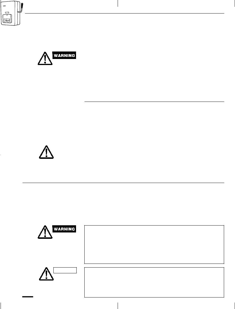
Warning Symbols
The following symbols are used in this manual to alert to potentially dangerous conditions to users and service personnel using this appliance:
This symbol refers to a hazard or unsafe practice which can result in severe personal injury or death.
CAUTION |
This symbol refers to a hazard or unsafe |
|
practice which can result in personal injury |
||
|
||
|
or product or property damage. |
OI-212-03EG |
3 |
Installation Location
·We recommend that this air conditioner be installed properly by qualified installation technicians in accordance with the Installation Instructions provided with the unit.
·Before installation, check that the voltage of the electric supply in your home or office is the same as the voltage shown on the nameplate.
|
|
· Do not install this air conditioner where there are fumes or flammable |
|
|
gases, or in an extremely humid space such as a greenhouse. |
|
|
· Do not install the air conditioner where excessively high heat- |
|
|
generating objects are placed. |
|
|
|
Avoid: |
· |
To protect the air conditioner from heavy corrosion, avoid installing the |
|
|
outdoor unit where salty sea water can splash directly onto it or in |
|
|
sulphurous air near a spa. |
|
· |
The unit may malfunction when the receiver in the indoor unit is |
|
|
exposed to the inverter lamp light. |
Electrical Requirements
1. |
All wiring must conform to the local electrical codes. Consult your |
|
|||
|
|
|
dealer or a qualified electrician for details. |
|
|
2. |
Each unit must be properly grounded with a ground (or earth) wire or |
||||
|
|
|
through the supply wiring. |
|
|
3. |
Wiring must be done by a qualified electrician. |
Power mains |
|
||
· |
|
Power supply: 60 Hz, single-phase, 230/208 volts. |
|
||
|
|
|
|||
|
|
|
|
|
ON |
CAUTION |
|
|
To warm up the system, the power mains must be |
|
|
|
|
|
turned on at least five (5) hours before operation. |
|
|
|
|
|
|
|
|
|
|
|
Leave the power mains ON unless you will not be |
|
|
|
|
|
using this appliance for an extended period. |
|
|
|
|
|
|
|
|
For ceiling-mounted and recessed-type indoor units, the flaps move for one minute when the power is supplied to the unit. This is not a malfunction.
Safety Instructions
·Read this Instruction Manual carefully before using this air conditioner. If you still have any difficulties or problems, consult your dealer for help.
·This air conditioner is designed to give you comfortable room conditions. Use this only for its intended purpose as described in this Instruction Manual.
· Never touch the unit with wet hands.
·Never use or store gasoline or other flammable vapor or liquid near the air conditioner Ð it is very dangerous.
·This air conditioner has no ventilator for intaking fresh air from outdoors. You must open doors or windows frequently when you use gas or oil heating appliances in the same room, which consume a lot of oxygen from the air. Otherwise there is a risk of suffocation in extreme cases.
CAUTION · Do not turn the air conditioner on and off from the power mains switch. Use the ON/OFF operation button.
·Do not stick anything into the air outlet of the outdoor unit. This is dangerous because the fan is rotating at high speed.
·Do not let children play with the air conditioner.
·Do not cool the room too much if babies or invalids are present.
4 |
OI-212-04EG |
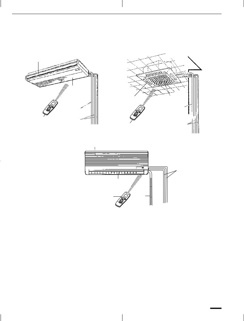
Names of Parts
Each air conditioner shown below consists of an indoor unit and an outdoor unit. You can control the air conditioner with the remote control unit.
Ceiling-mounted type |
Recessed type |
Air outlet
Air intake
|
|
Air outlet |
Air intake |
|
Drain tube |
|
Drain tube |
|
|
|
|
Remote |
Refrigerant |
|
|
control |
tubes |
Remote control |
Refrigerant |
unit |
|
unit |
tubes |
Wall-mounted type
Air intake
|
|
|
|
|
|
Refrigerant |
|
|
|
Air outlet |
|
|
tubes |
|
|
|
|
|
||
|
|
|
|
|
|
|
|
|
|
|
|
|
|
|
|
|
|
|
|
|
|
|
|
|
|
|
|
|
|
|
Remote control unit |
Drain |
||
|
|
|
|
tube |
||
|
|
This illustration is based on the external view of a standard model. |
||||
|
NOTE |
|
||||
|
|
|
Consequently, the shape may differ from that of the air conditioner which |
|||
|
|
|
||||
|
|
|
you have selected. |
|
|
|
|
|
|
|
|||
Air intake |
The return air in the room is drawn into this section and passes through |
|||||
|
|
|
air filters which remove dust and foreign particles. |
|||
Air outlet |
Conditioned air is returned to the room through the air outlet (ceiling |
|||||
|
|
|
and wall-mounted type) or four air outlets (Recessed type). |
|||
|
|
|
The direction of airflow can be adjusted as desired using the remote |
|||
|
|
|
control unit. |
|
|
|
|
|
|
|
|||
Remote control unit |
The wireless remote control unit controls power ON/OFF, operation |
|||||
|
|
|
mode selection, temperature, fan speed, timer setting, and air sweeping. |
|||
|
|
|
|
|||
Refrigerant tubes |
The indoor and outdoor units are connected by copper tubes through |
|||||
|
|
|
which refrigerant gas flows. |
|
|
|
|
|
|
|
|||
Drain tube |
Moisture in the room is condensed and drains off by means of this tube. |
|||||
|
|
|
|
|||
Outdoor (condensing) unit |
The outdoor unit contains the compressor, fan motor, heat exchanger |
|||||
|
|
|
coil, and other electrical components. |
|||
OI-212-05EG |
5 |

Unit Display and Operation Selector
Recessed type |
Ceiling-mounted type |
OPERATION |
TIMER |
STANDBY |
Remote |
lamp |
lamp |
lamp |
control |
|
|
|
receiver |
Recessed type |
Ceiling-mounted type |
Operation selector
ADDRESS
1.TEST RUN 2.PCB CHK(ON) 3.RCU MAIN (OFF) 4.(OFF)
SERVICING ADDRERS NORM./ SWEEP |
ON/OFF |
||
switches switch HOLD button |
operation |
||
switch |
button |
||
|
|
|
|
|
|
|
|
ADDRESS
1.TEST RUN 2.PCB CHK(ON) 3.RCU MAIN (OFF) 4.(OFF)
Finger-hold
Air intake grille
Air intake grille
Air filter
SERVICING ADDRESS NORM./ SWEEP ON/OFF
switches |
switch |
HOLD |
button operation |
|
|
switch |
button |
Operation selector
6 |
OI-212-06EG |
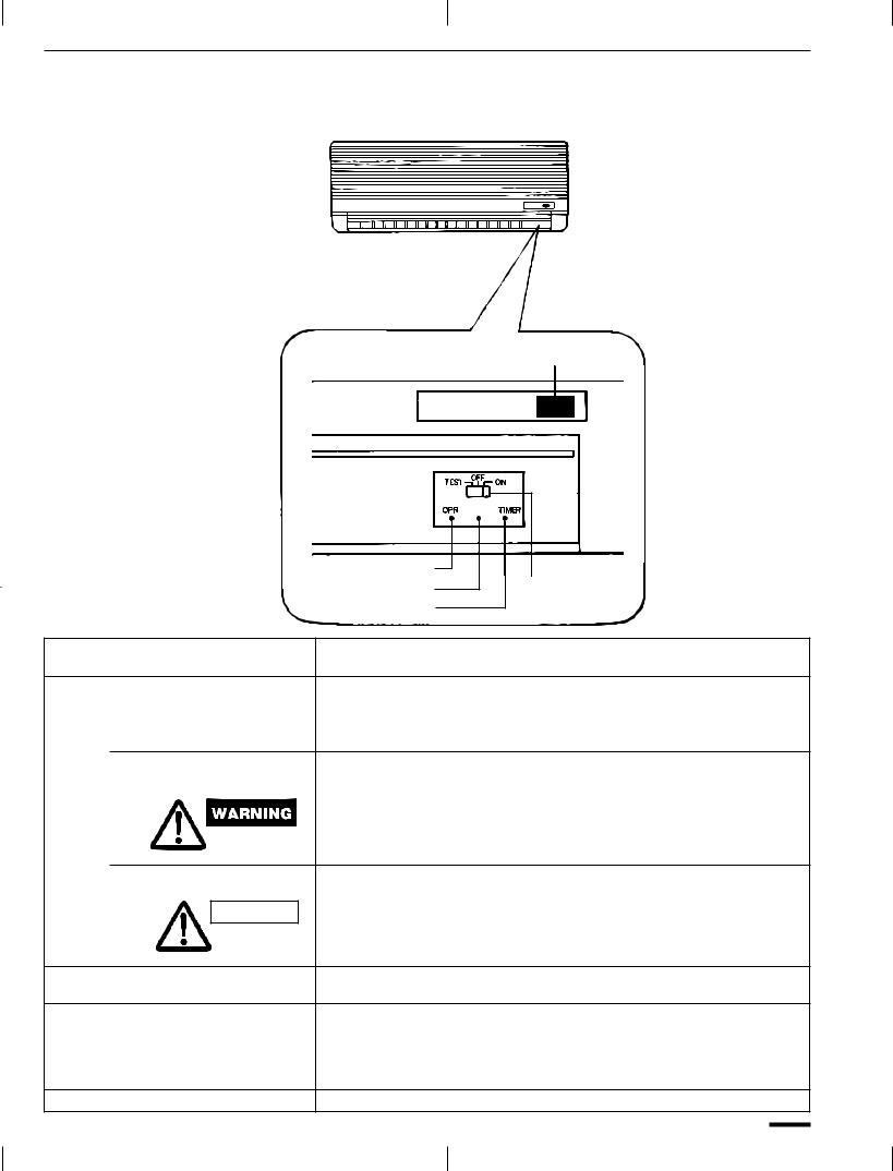
Unit Display and Operation Selector (continued)
INDOOR UNIT
REMOTE CONTROL receiver
|
STANDBY |
OPERATION lamp |
|
STANDBY lamp |
Operation selector |
TIMER lamp |
|
REMOTE CONTROL |
This section picks up infrared signals from the remote control unit |
receiver |
(transmitter). |
Operation selector
ON position This position is for operating the air conditioner with the wireless remote control unit.
The selector should normally be set in this position.
OFF position Switch the selector to the OFF position if you are not going to use the air conditioner for a few days or longer.
The OFF position does not disconnect the power. Use the main power switch to turn off power completely.
TEST position This position is used only when servicing the air conditioner.
CAUTION |
Do not set at the TEST position for normal operation. |
|
OPERATION lamp This lamp lights when the system is in the continuous AUTO, HEAT, COOL or FAN mode.
STANDBY lamp This lamp lights when the system is warming up for heating and when the system is defrosting. To keep a constant room temperature, the air conditioner continues to supply a gentle breeze when warming up or when the heating operation is paused by the thermostat.
TIMER lamp This lamp lights when the system is being controlled by the timer.
OI-212-07EG |
7 |
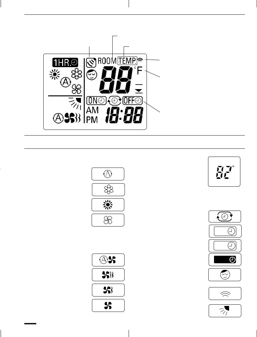
Remote Control Unit (Display)
Displayed when main unit sensor is in use
“ROOMTEMP” is displayed when the temperature setting has not been made.
“TEMP” is displayed when setting temperature.
Displayed when transmitting data
Displayed when temperature is shown

 Displayed when the temperature setting is at the upper or lower allowable limit
Displayed when setting timer
Symbols
(1)Operation mode
AUTO.......................................
COOLING.................................
HEATING .................................
FAN ..........................................
(2)Fan speed
Automatic operation ..............
HIGH ........................................
MEDIUM..................................
LOW.........................................
(3) Set temperature |
|
60 ± 86 °F |
F |
When set to 82 °F ........... |
|
Current temperature |
|
indication ......................... |
|
(4) Timer
|
24-hour clock with ON/OFF |
|
|
Program Timer ....................... |
|
|
24-hour ON Timer.................. |
ON |
|
|
|
|
24-hour OFF Timer................. |
OFF |
|
|
|
|
1-hour OFF Timer |
1HR. |
|
|
|
(5) |
NIGHT SETBACK .................... |
|
(6) |
Confirmation of |
|
|
transmission ........................... |
|
(7) |
Sweep indication.................... |
|
8 |
OI-212-08EG |
 Loading...