

SANYO STK4042II Datasheet
Thick Film Hybrid IC
Ordering number : EN4479A
N3096HA (OT)/82793YO 5-2300 No. 4479-1/3
SANYO Electric Co.,Ltd. Semiconductor Bussiness Headquarters
TOKYO OFFICE Tokyo Bldg., 1-10, 1 Chome, Ueno, Taito-ku, TOKYO, 110 JAPAN
AF Power Amplifier (Split Power Supply)
(80 W min, THD = 0.4%)
STK4042 II
Features
• Miniature package allows audio sets to be made
slimmer.
• Pin-compatible amplifiers with outputs of 20 to
200 W are available.
• Facilitates thermal design of slim stereo sets by
distributing the heat dissipating ICs in the set.
• The adoption of constant current circuits reduces pop
noise when the power supply is turned on or off.
• Supports the design of supplementary electronic circuits
(thermal shutdown, load short protection, and pop noise
muting at power on and off).
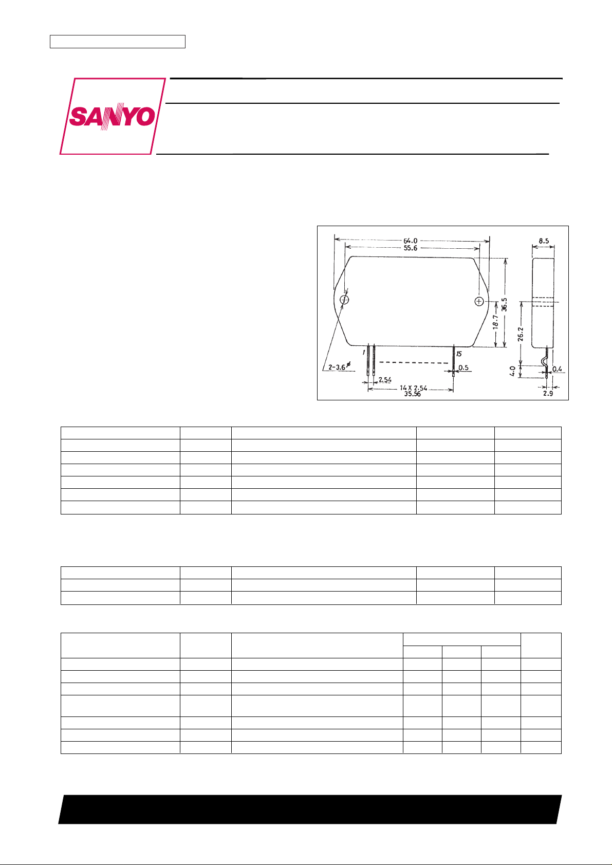
Package Dimensions
unit: mm
4075
Specifications
Maximum Ratings at Ta = 25°C
Parameter Symbol Condition Rating Unit
Maximum supply voltage V
CC
max ±65 V
Thermal resistance
θj-c 1.2 °C/W
Junction temperature Tj 150 °C
Operating case temperature Tc 125 °C
Storage temperature Tstg –30 to +125 °C
Available time for load shorted t
S
* VCC= ±45 V, RL= 8 Ω, f = 50 Hz, PO= 80 W 2 s
Note: Use a constant voltage power supply as the test power supply unless otherwise specified.
* Use the transformer power supply shown on the next page when measuring the available time for load shorted and the output noise voltage.
Recommended Operating Conditions at Ta = 25°C
Parameter Symbol Condition Rating Unit
Recommended supply voltage V
CC
±45 V
Load resistance R
L
8 Ω
Operating Characteristics at Ta = 25°C, VCC= ±45 V, RL= 8 Ω (noninductive load), Rg = 600 Ω, VG = 40 dB
Rating
Parameter Symbol Condition
min typ max
Unit
Quiescent current I
CCO
VCC= ±54 V 15 120 mA
Output power P
O
THD = 0.4%, f = 20 Hz to 20 kHz 80 W
Total harmonic distortion THD P
O
= 1.0 W, f = 1 kHz 0.3 %
Frequency response f
L
, f
H
PO= 1.0 W, +0dB 20 to 50 k Hz
–3
Input resistance r
i
PO= 1.0 W, f = 1 kHz 55 kΩ
Output noise voltage V
NO
** VCC= ±54 V, Rg = 10 kΩ 1.2 mVrms
Neutral voltage V
N
VCC= ±54 V –70 0 +70 mV
Note: Use a constant voltage power supply as the test power supply unless otherwise specified.
** The output noise voltage is the peak value measured with an averaging rms scale volt meter. The noise voltage waveform should not include
pulse noise.
[STK4042II]
STK4042 II
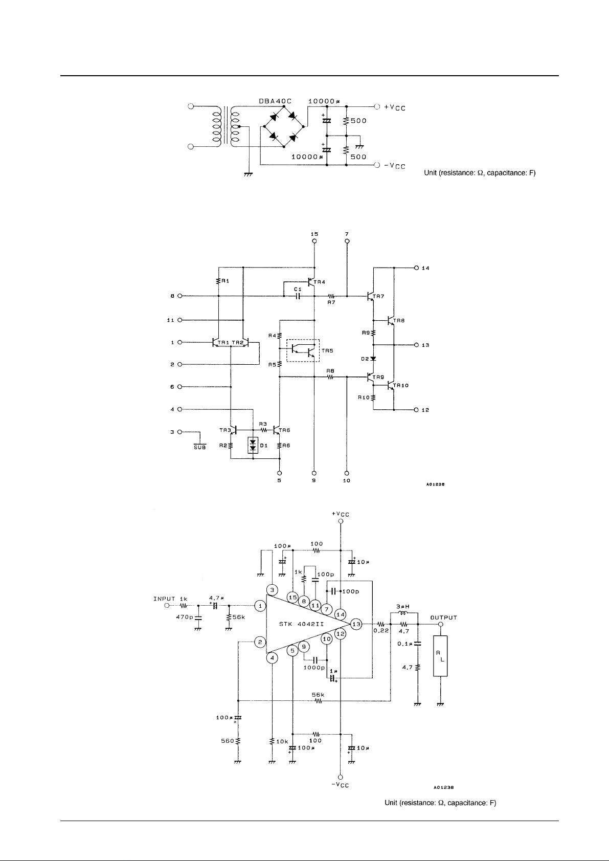
Equivalent Circuit
Sample Application Circuit: 80 W (minimum) AF Power Amplifier
No. 4479-2/3
Specified Transformer Power Supply
(MG-200 equivalent)
 Loading...