

Sanyo SAP-KRV9AEH,SAP-CRV9AEH,SAP-KRV12AEH,SAP-CRV12AEH Installation Instructions Manual
Español
Français
Deutsch
Italiano
Português
EEÏÏÏÏËËÓÓÈÈÎο¿
English
– Inverter Split System Air Conditioner –
COOL/DRY/HEAT Model
85264190527000 © SANYO 2010 SANYO Electric Co., Ltd.
Osaka, Japan
W
Contents
Page
IMPORTANT!
Please Read Before Starting .................................. 2
1. REQUIREMENTS FOR INSTALLATION ........... 3
1-1. Basic Requirements for Installation Location
1-2. Indoor Unit Installation Position Selection
1-3. Outdoor Unit Installation Position Selection
1-4. Safety Requirements for Electrical Devices
1-5. Grounding (Earthing) Requirements
1-6. Type of Copper Tube and Insulation Material
1-7. Other Wiring Considerations
2. INSTALLATION DIMENSION DIAGRAM........... 5
3. INSTALL INDOOR UNIT ..................................... 6
3-1. Install the Rear Panel
3-2. Install the Tubing Hole
3-3. Install the Drain Hose
3-4. Connect the Indoor and Outdoor Wiring
3-5. How to Install the Indoor Unit
4. INSTALL OUTDOOR UNIT ............................... 10
4-1. Wiring Instructions for the Outdoor Unit
4-2. Refrigerant Tubing
4-3. Air Purging
4-4. Tubing Length
4-5. Outdoor Condensation Drainage
4-6. Accessories
5. PUMP DOWN .................................................... 16
5-1. What is Pump Down?
5-2. Pump Down Procedure
6. CHECK AFTER INSTALLATION AND
TEST RUN......................................................... 17
6-1. Check After Installation
6-2. Test Run
7. ELECTRIC WIRING SYSTEM .......................... 18
INSTALLATION INSTRUCTIONS
Model Combinations
Combine indoor and outdoor units only as listed
below.
Indoor Unit Outdoor Unit
SAP-KRV9AEH SAP-CRV9AEH
SAP-KRV12AEH SAP-CRV12AEH
Powe r S ource:
50 Hz, single-phase, 220 – 240 VAC
This air conditioner uses the new refrigerant R410A.
The illustrations are based on the typical appearance
of a standard model. Consequently, the shape may
differ from that of the air conditioner that you are
installing.
NOTE
2
English
IMPORTANT!
Please Read Before Starting
This air conditioning system meets strict safety and operating standards. As the installer or service person, it is an
important part of your job to install or service the system so
it operates safely and efficiently.
For safe installation and trouble-free operation, you
must:
!
Carefully read this instruction booklet before beginning.
!
Follow each installation or repair step exactly as
shown.
!
Observe all local, state, and national electrical codes.
!
Pay close attention to all warning and caution notices
given in this manual.
This symbol refers to a hazard
or unsafe practice which can
result in severe personal injury
or death.
This symbol refers to a hazard
or unsafe practice which can
result in personal injury or
product or property damage.
If Necessary, Get Help
These instructions are all you need for most installation
sites and maintenance conditions. If you require help for
a special problem, contact our sales/service outlet or
your certified dealer for additional instructions.
In Case of Improper Installation
The manufacturer shall in no way be responsible for
improper installation or maintenance service, including
failure to follow the instructions in this document.
SPECIAL PRECAUTIONS
When Wiring
ELECTRICAL SHOCK CAN CAUSE
SEVERE PERSONAL INJURY OR DEATH.
ONLY A QUALIFIED, EXPERIENCED
ELECTRICIAN SHOULD ATTEMPT TO
WIRE THIS SYSTEM.
•Do not supply power to the unit until all wiring and tub-
ing are completed or reconnected and checked.
•Highly dangerous electrical voltages are used in this
system. Carefully refer to the wiring diagram and
these instructions when wiring. Improper connections
and inadequate grounding can cause accidental
injury or death.
•Ground the unitfollowing local electrical codes.
•Connect all wiring tightly. Loose wiring may cause
overheating at connection points and a possible fire
hazard.
•Install a protective leakage breaker depending on the
installation location (especially a damp or humid location). If a leakage breaker is not installed, electric
shock can occur.
When Transporting
Be careful when picking up and moving the indoor and
outdoor units. Get a partner to help, and bend your knees
when lifting to reduce strain on your back. Sharp edges or
thin aluminum fins on the air conditioner can cut your fingers.
When Installing…
…In a Ceiling or Wall
Make sure the ceiling/wall is strong enough to hold the
unit’s weight. It may be necessary to construct a strong
wood or metal frame to provide added support.
…In a Room
Properly insulate any tubing run inside a room to prevent
“sweating” that can cause dripping and water damage to
walls and floors.
…In Moist or Uneven Locations
Use a raised concrete pad or concrete blocks to provide
a solid, level foundation for the outdoor unit. This prevents water damage and abnormal vibration.
…In an Area with High Winds
Securely anchor the outdoor unit down with bolts and a
metal frame. Provide a suitable air baffle.
…In a Snowy Area
•
Position the outdoor unit in a protected location
where snow will not blow into it.
• Install the outdoor unit on a raised platform that is
higher than drifting snow. Provide snow vents.
When Connecting Refrigerant Tubing
•Use the flare method for connecting tubing.
•Apply refrigerant lubricant to the matching surfaces of
the flare and union tubes before connecting them, then
tighten the nut with a torque wrench for a leak-free
connection.
•Check carefully for leaks before starting the test run.
When Servicing
•Turn the power OFFat the main power box (mains)
before opening the unit to check or repair electrical
parts and wiring.
•Keep your fingers and clothing away from any moving
parts.
•Clean up the site after you finish, remembering to
check that no metal scraps or bits of wiring have been
left inside the unit being serviced.
Others
•Ventilate any enclosed areas when installing or testing
the refrigeration system. Escaped refrigerant gas, on
contact with fire or heat, can produce dangerously
toxic gas.
•Confirm upon completing installation that no refrigerant
gas is leaking. If escaped gas comes in contact with a
stove, gas water heater, electric room heater or other
heat source, it can produce dangerously toxic gas.
WARNING
WARNING
CAUTION
CAUTION

3
English
1. Requirements for Installation
1-1. Basic Requirements for Installation Location
Installation in any of the following locations may lead to
a malfunction. If this is unavoidable, before beginning
please contact our service center.
(1) A location where a strong heat source, vapor or
flammable gas, or any easily ignitable material is
present.
(2) A location where high-frequency waves are gener-
ated by radio equipment, welding equipment, or
medical equipment, etc.
(3) A location where salt spray is present, such as in
coastal areas, or in a corrosive salt environment.
(4) A location where sulfuric gas is present, such as
may be generated by hot springs.
(5) A location where oil mist is present in the air.
(6) Any other location with unusual or potentially
hazardous circumstances.
1-2. Indoor Unit Installation Position Selection
(1) The air inlet and outlet vents should not be near
any obstructions. Be sure that the discharged air
can reach the entire room.
(2) Select a location where water from condensation
can easy drain to the outside, and where the indoor
unit can be easily connected to the outdoor unit.
(3) Select a location that cannot be easily reached by
small children.
(4) Select a location that will support the full weight of
the unit, will be unaffected by vibration, and not
result in increased noise levels.
(5) Leave enough space to allow for routine mainte-
nance. The height of the installation location should
be 150 cm or more from the floor.
(6) Install the indoor unit more than 1 meter away from
any antenna or power lines or connecting wires
used for television, radio, telephone, security system, or intercom. Electrical noise from any of these
sources may affect operation.
(7) Select a location where the air filter can be easily
removed.
(8) Confirm that the installation location and dimen-
sions are in accordance with the dimensions in the
installation diagram (page 5).
1-3. Outdoor Unit Installation Position Selection
(1) Select a location where air discharge and operating
noise will not bother the neighbors, nor harm animals or plants.
(2) Select a location with adequate ventilation.
(3) Select a location where there are no obstructions
that can block the air intake and discharge vents.
(4) Select a location that will support the full weight of
the unit, will be unaffected by vibration, and permit
safe installation.
(5) Select a dry location, and do not expose the unit to
direct sunlight or strong wind.
(6) Confirm that the installation location and dimen-
sions are in accordance with the dimensions in the
installation diagram (page 5), and allow for adequate space for maintenance and repairs.
(7) The height difference of the connected tubing must
be within 5 m, and the length of the connected
tubing must be within 10 m.
(8) Select a location that cannot be easily reached by
small children.
(9) Select a location that does not block any passage-
way, and which does not cause a public eyesore.
4
English
1-4. Safety Requirements for Electrical Devices
(1) Use an independent circuit of the rated AC voltage
exclusive of any other devices and only with the
specified cable diameter.
(2) Applicable voltage operating range: 198 – 264 VAC
(3) Do not forcefully pull on the power cable or sus-
pend it without adequate support, either horizontally or vertically.
(4) Be sure to properly ground (earth) the device to a
reliable grounding point in accordance with local
electrical codes and using an approved grounding
connector. All wiring should be done only by a professional electrician.
•A surge protector should be installed in the
exclusive circuit along with a correctly
sized breaker switch.
•The breaker switch (thermal/magnetic type)
must be of proper capacity to serve as protection against short circuit and power overload.
(5) The minimum distance from the unit to any
inflammable object or material is 1.5 m.
•The power supply wiring must be correctly and
tightly connected, with no internal short circuit or
leakage.
•A wrong connection may result in a fire hazard or
system misoperation.
1-5. Grounding (Earthing) Requirements
(1) This air conditioner is a Type 1 device and must be
grounded (earthed) accordingly. Be sure to follow
all local electrical codes.
(2) The power supply circuit must include a safe and
reliable ground. DO NOT connect the ground/earth
wire to any of the following:
– Gas pipe
– Tap water pipe
– Sewage pipe
– Any other point that does not meet electrical
codes.
1-6. Type of Copper Tube and Insulation Material
If you wish to purchase these materials separately
from a local source, you will need:
(1) Deoxidized annealed copper tube for refrigerant
tubing.
Cut each tube to the appropriate lengths +30 cm to
40 cm to dampen vibration between units.
(2) Foamed polyethylene insulation for the specified
copper tubes as required to precise length of tubing. Wall thickness of the insulation should be not
less than 8 mm.
(3) Use insulated copper wire for field wiring. Wire size
varies with the total length of wiring. Refer to 3-4-1.
Wiring Instructions for details.
1-7. Other Wiring Considerations
(1) Wire only in accordance with the methods given in
this manual for both power and inter-unit signal
control, and carefully following the circuit diagram
affixed to the unit for each isolated component.
(2) The type and rating of the fuse used should comply
with the label on the controller or fuse device.
(3) The external static pressure when testing is “0Mpa.”
NOTE
NOTE
Narrow Tube Wide Tube
Outer Dia. Thickness Outer Dia. Thickness
6.35 mm 0.8 mm 9.52 mm 0.8 mm
5
English
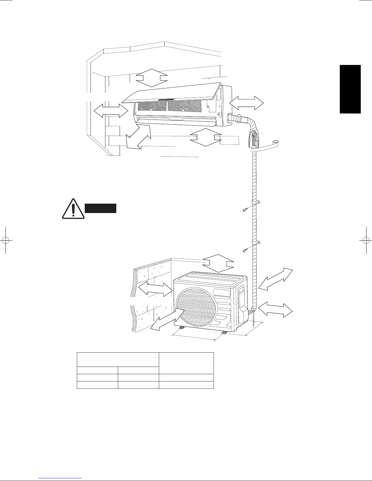
2. Installation Dimension Diagram
Distance to ceiling
Distance to wall
15 cm or more
•
The dimensions of the space necessary for correct
installation of the appliance including the minimum
permissible distances to adjacent structures.
WARNING
15 cm
or more
15 cm or more
150 cm
300 cm
or more
Air outlet side
Distance to floor
or more
To prevent abnormal heat generation
and the possibility of fire, do not place
obstacles, enclosures, or grilles in front of
or surrounding the air conditioner in a way
that may block air flow.
Distance to wall
Distance to nearby obstructions
30 cm or more
Distance to wall
Air outlet side
Outdoor Unit Installation
A
470 mm
470 mm
Dimension
B
299 mm SAP-CRV9AEH
200 cm or more
SAP-CRV12AEH299 mm
Model
50 cm
or more
Air intake side
30 cm or more
Distance to wall
50 cm or more
A
B
6
English
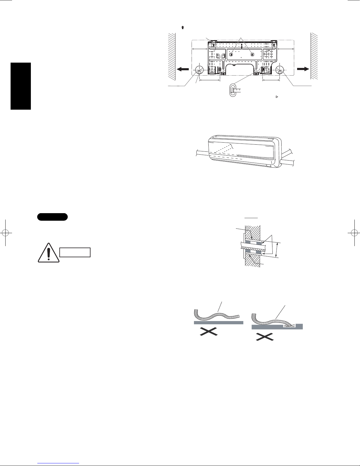
Fig. 12
Fig. 13
3. Install Indoor Unit
3-1. Install the Rear Panel
(1) Install the rear panel horizontally using a car-
penter’s level or inclinometer. Since the unit
was designed for water drainage to either the
left or right direction, depending on the outlet
side you require provide a slight downward gradient to ensure adequate drainage of the water
pan in the correct direction. (Fig. 11)
(2) Fix the rear panel to the wall using screws
required for the wall type. Use plaster board fasteners / toggle bolts for hollow walls.
(3) Be sure to affix the rear panel securely enough to
hold the weight on an adult (at least 60 kg), with
attachment screws spaced to evenly divide the
weight of the unit.
3-2. Install the Tubing Hole
(1) Determine which side of the unit you should make
the hole for tubing and wiring. (Fig. 12)
(2) Make the tubing hole (ø65 mm) in the wall at a
slight downward slant to the outdoor side. (Fig. 13)
Before making the hole, check carefully that no studs
or pipes are directly run behind the spot to be cut.
The above precautions are also applicable if tubing
goes through the wall in any other location.
(3) Insert a PVC pipe in the hole to prevent the con-
nection piping and wiring from being damaged
when passing through the hole.
3-3. Install the Drain Hose
(1) The drain hose must be angled at a downward
slant for smooth, unimpeded drainage.
(2) Supply adequate support for the hose, and do not
pull on it or permit bends or water traps to occur.
The outlet end must not be immersed in water or
otherwise blocked. (Fig. 14)
(3) When extending the drain hose inside a room,
cover it with adequate insulation to prevent condensation and dripping. This is important to avoid
damage to walls, floors, or room furnishings.
NOTE
Fig. 14
CAUTION
Also avoid areas where
electrical wiring or conduits
are located.
Fig. 11
Recommended mounting plate
retention spots
(5 spots in all)
Space
to wall
150 mm
or more
Left side
ø65 mm
(Rear tubing hole)
Drain hose position
Left
tubing
120.5
mm
160
mm
Place a carpenter's level on raised tab.
160
mm
Use tape measure
as shown.
Position the end of
a tape measure at
.
101
mm
Space
to wall
150 mm
or more
Right side
ø65 mm
(Rear tubing hole)
Right-rear tubing
(recommended)
WallWall
Left-rear
tubing
downward
slant to
outdoor side
No water traps
Indoor
Slight
Right tubing
Outdoor
Sealing putty
or stuffing
ø65 mm
PVC pipe
Avoid bent hose
No pooled water
or other blockage
 Loading...