

Sanyo SAP-KRV96EHDS,SAP-CRV96EHDS,SAP-KRV126EHDS,SAP-CRV126EHDS Technical & Service Manual
TECHNICAL & SERVICE MANUAL
SAP-KRV96EHDS + SAP-CRV96EHDS
SAP-KRV126EHDS + SAP-CRV126EHDS
DC INVERTER SPLIT SYSTEM AIR CONDITIONER
Indoor Model No.
SAP-KRV96EHDS
SAP-KRV126EHDS
Indoor Unit
Product Code No.
1 852 340 69
1 852 340 70
FILE NO.
Destination: Europe
Outdoor Model No.
SAP-CRV96EHDS
SAP-CRV126EHDS
Product Code No.
1 852 340 73
1 852 340 74
Outdoor Unit
SAP-KRV96EHDS
SAP-KRV126EHDS
SAP-CRV96EHDS
SAP-CRV126EHDS
REFERENCE NO. SM700708
RoHS
WARNING
• This product does not contain any hazardous substances prohibited by the RoHS Directive.
These air conditioners employ new refrigerant R410A.
Pay special attention when servicing the unit.
• You are requested to use RoHS compliant parts for maintenance or repair.
• You are requested to use lead-free solder.
A
IR
C
O
N
DITIONER
When Wiring
ELECTRICAL SHOCK CAN CAUSE
SEVERE PERSONAL INJURY OR DEATH.
ONLY A QUALIFIED, EXPERIENCED
ELECTRICIAN SHOULD ATTEMPT TO
WIRE THIS SYSTEM.
SPECIAL PRECAUTIONS
This symbol refers to a hazard
or unsafe practice which can
result in severe personal
injury or death.
This symbol refers to a hazard
or unsafe practice which can
result in personal injury or
product or property damage.
CAUTION
CAUTION
WARNING
WARNING
Important!
Please Read Before Starting
This air conditioning system meets strict safety and
operating standards. As the installer or service person, it
is an important part of your job to install or service the
system so it operates safely and efficiently.
For safe installation and trouble-free operation, you
must:
Carefully read this instruction booklet before beginning.
Follow each installation or repair step exactly as shown.
Observe all local, state, and national electrical codes.
Pay close attention to all warning and caution notices
given in this manual.
If Necessary, Get Help
These instructions are all you need for most installation
sites and maintenance conditions. If you require help for
a special problem, contact our sales/service outlet or
your certified dealer for additional instructions.
In Case of Improper Installation
The manufacturer shall in no way be responsible for
improper installation or maintenance service, including
failure to follow the instructions in this document.
Do not supply power to the unit until all wiring and
tubing are completed or reconnected and checked.
Highly dangerous electrical voltages are used in this
system. Carefully refer to the wiring diagram and these
instructions when wiring. Improper connections and
inadequate grounding can cause accidental injury or
death.
Ground the unit following local electrical codes.
Connect all wiring tightly. Loose wiring may cause
overheating at connection points and a possible fire
hazard.
When Transporting
Be careful when picking up and moving the indoor and
outdoor units. Get a partner to help, and bend your knees
when lifting to reduce strain on your back. Sharp edges or
thin aluminum fins on the air conditioner can cut your
fingers.
When Installing
In a Ceiling or Wall
Make sure the ceiling/wall is strong enough to hold the
unit’s weight. It may be necessary to construct a strong
wood or metal frame to provide added support.
In a Room
Properly insulate any tubing run inside a room to prevent
"sweating" that can cause dripping and water damage to
walls and floors.
In Moist or Uneven Locations
Use a raised concrete pad or concrete blocks to provide a
solid, level foundation for the outdoor unit. This prevents
water damage and abnormal vibration.
In an Area with High Winds
Securely anchor the outdoor unit down with bolts and a
metal frame. Provide a suitable air baffle.
In a Snowy Area (for Heat Pump-type Systems)
Install the outdoor unit on a raised platform that is higher
than drifting snow. Provide snow vents.
When Connecting Refrigerant Tubing
Use the flare method for connecting tubing.
Apply refrigerant lubricant to the matching surfaces of
the flare and union tubes before connecting them, then
tighten the nut with a torque wrench for a leak-free
connection.
Check carefully for leaks before starting the test run.
When Servicing
Tu rn the power off at the main power box (mains) before
opening the unit to check or repair electrical parts and
wiring.
Keep your fingers and clothing away from any moving
parts.
Clean up the site after you finish, remembering to check
that no metal scraps or bits of wiring have been left
inside the unit being serviced.
Others
Ventilate any enclosed areas when installing or testing
the refrigeration system. Escaped refrigerant gas, on
contact with fire or heat, can produce dangerously toxic
gas.
Confirm upon completing installation that no refrigerant
gas is leaking. If escaped gas comes in contact with a
stove, gas water heater, electric room heater or other
heat source, it can produce dangerously toxic gas.
•
•
•
•
•
•
•
•
•
•
•
•
2

Table of Contents
1. OPERATING RANGE
2. SPECIFICATIONS
2-1. Unit Specifications
2-2. Major Component Specifications
2-3. Other Component Specifications
3. DIMENSIONAL DATA
4. REFRIGERANT FLOW DIAGRAM
4-1. Refrigerant Flow Diagram
5. PERFORMANCE DATA
5-1. Temperature Charts
5-2. Air Throw Distance Charts
6. ELECTRICAL DATA
6-1. Electrical Characteristics
6-2. Electric Wiring Diagrams
7. INSTALLATION INSTRUCTIONS
7-1. Installation Site Selection
7-2. Recommended Wire Length and Diameter
7-3. Remote Control Unit Installation Position
7-4. How to Test Run the Air Conditioner
7-5. Remove the Grille to Install the Indoor Unit
8. MAINTENANCE
8-1. Address Setting of the Remote Control Unit
8-2. Removing and Mounting the Drain Hose
8-3. Removing the Grill
8-4. Removing the Electrical Component Box
8-5. Removing the P.C.Board
8-6. Removing the Panel Motor
8-7. Removing and Mounting the UV antibacterial filtration unit
8-8. Removing the Drain Pan (Air Outlet Ass'y)
8-9. Removing and Mounting the Fan Motor
8-10. Removing the Fan
8-11. Disconnecting and Connecting Positive Connector for Outdoor Unit
9. FUNCTIONS
9-1. Operation Functions
9-2. Protective Functions
5
6
8
12
13
15
16
18
20
21
23
25
26
27
28
29
30
30
31
33
33
34
35
36
37
38
39
41
...................................................................................................................
.............................................................................................................
.......................................................................................
.......................................................................................
.....................................................................................................................
...................................................................................................
............................................................................................................
.................................................................................................
....................................................................................................
....................................................................................................
...................................................................................................
........................................................................
...........................................................................
...................................................................................
........................................................................
.......................................................................
............................................................................
...............................................................................................................
...........................................................................
.....................................................................................................
.................................................................................................
................................................
.........................................................................
..............................................................................
..............................................................................................................
.................................
...........................................................................................................
...........................................................................................................
Page
3

10. TROUBLESHOOTING
10-1. Precautions before Performing Inspection or Repair
10-2. Method of Self-Diagnostics
10-3. Checking the Indoor and Outdoor Units
10-4. Trouble Diagnosis of Fan Motor
10-5. Noise Malfunction and Electromagnetic Interference
10-6. Checking and Troubleshooting when the Front Panel fails to work
11. CHECKING ELECTRICAL COMPONENTS
11-1. Measurement of Insulation Resistance
11-2. Checking Continuity of Fuse on PCB Ass'y
12. REFRIGERANT R410A:
SPECIAL PRECAUTIONS WHEN SERVICING UNIT
12-1. Characteristics of New Refrigerant R410A
12-2. Checklist before Servicing
12-3. Tools Specifically for R410A
12-4. Tubing Installation Procedures
12-5. In Case of Compressor Malfunction
12-6. In Case Refrigerant is Leaking
12-7. Charging Additional Refrigerant
12-8. Retro-Fitting Existing Systems
APPENDIX INSTRUCTION MANUAL
43
43
45
48
50
51
53
54
55
55
57
57
59
60
61
61
62
...........................................................
.................................................................................................
..............................................................................
..........................................................................................
..........................................................
.....................................
...............................................................................
.........................................................................
.........................................................................
...................................................................................................
................................................................................................
............................................................................................
....................................................................................
............................................................................................
..........................................................................................
............................................................................................
............................................................................................
Page
4

1. OPERATING RANGE
Maximum
Minimum
Maximum
Minimum
32 °C D.B. / 23 °C W.B.
19 °C D.B. / 14 °C W.B.
27 °C D.B.
16 °C D.B.
43 °C D.B.
–15 °C D.B.
24 °C D.B. / 18 °C W.B.
_
D.B. / –15 °C W.B.
Temperature Indoor Air Intake Temp. Outdoor Air Intake Temp.
Cooling
Heating
5
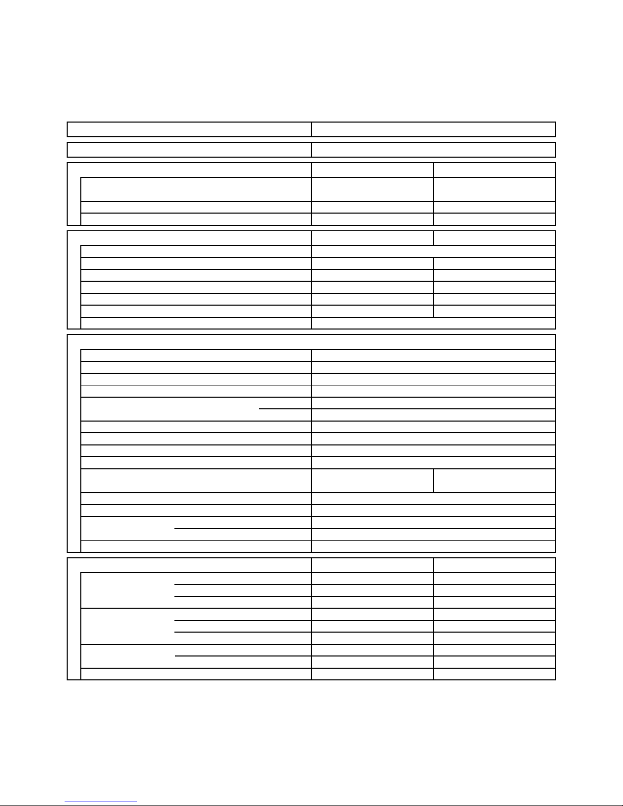
2. SPECIFICATIONS
2-1. Unit Specifications
Indoor Unit SAP-KRV96EHDS
Outdoor Unit SAP-CRV96EHDS
DATA SUBJECT TO CHANGE WITHOUT NOTICE.
Remarks: Rating conditions are:
Cooling: Indoor air temperature 27°C D.B. / 19°C W.B.
Outdoor air temperature 35°C D.B. / 24°C W.B.
Heating: Indoor air temperature 20°C D.B.
Outdoor air temperature 7°C D.B. / 6°C W.B.
Vertical
dB-A
dB-A
Indoor : Hi/Me/Lo/Qt*
Outdoor : Hi
Air Filter
Compressor
Refrigerant / Amount charged at shipment g
Refrigerant Control
( 0.9 to 4.9 )
( 3,100 to 16,700 )
3.26
630
( 1.29 to 5.38 )
( 250 to 1,040 )
4.03
835
( 1.21 to 6.76 )
( 250 to 1,400 )
2.65
9,000
3.60
11,900
( 0.9 to 3.6 )
( 3,100 to 12,200 )
Shipping Volume
Cooling Heating
480
1.6
Cooling Heating
Depth
Net
Shipping
Package Dimensions
Weight
Width
Depth
Height
Width
mm
kg
kg
m
3
mm
mm
mm
mm
230V
mm
500
-
198 to 264
Dimensions & Weight
(*Qt = Quiet mode)
Refrigerant Tubing Connections
Unit Dimensions Height
Operation Sound
Electrical Rating
Air Circulation (High)
Moisture Removal (High)
WPower Input
V
A
Available Voltage Range
Running Amperes
Refrigerant Tube Kit / Accessories
Narrow tube
Wide tube
Refrigerant mm (in.)
Tube Diameter mm (in.)
0.21
38.0
325
9.5
367
36.0
11.5
0.06
619
931
789
180
790
265
239
862
Outdoor UnitIndoor Unit
265 565
6.35 (1/4)
9.52 (3/8)
mMax. allowable tubing length at shipment
Flare Type
7.5
41 / 35 / 28 / 2241 / 35 / 28 / 22
4645
R410A / 1,200
Electric Expansion Valve
Washable, Anti-Mold
DC Rotary (Inverter)
Manual
Auto
Timer
Indoor / Outdoor Fan Speeds
24-Hour ON or OFF Timer, 1-Hour OFF Timer
Auto and 3 steps / Auto (Hi, Me, Lo)
Airflow Direction (Indoor) Horizontal
Controls / Temperature Control
Control Unit
Microprocessor / I.C. Thermister
Wireless Remote Control Unit
Features
C.O.P.
Compressor Locked Rotor Amperes
W/W
Optional / Air Clean Filter
kW
Performance
- 4.31
%Power Factor 84 90
A 8.5
Power Source
Voltage Rating
Liters/h
BTU/h
Capacity
m
3
/h
220 to 240V Single-Phase 50Hz
E.E.R. W/W 4.21 -
6

Indoor Unit SAP-KRV126EHDS
Outdoor Unit SAP-CRV126EHDS
DATA SUBJECT TO CHANGE WITHOUT NOTICE.
Remarks: Rating conditions are:
Cooling: Indoor air temperature 27°C D.B. / 19°C W.B.
Outdoor air temperature 35°C D.B. / 24°C W.B.
Heating: Indoor air temperature 20°C D.B.
Outdoor air temperature 7°C D.B. / 6°C W.B.
Vertical
dB-A
dB-A
Indoor : Hi/Me/Lo/Qt*
Outdoor : Hi
Air Filter
Compressor
Refrigerant / Amount charged at shipment g
Refrigerant Control
( 0.9 to 5.4 )
( 3,100 to 18,400 )
4.79
1,025
( 1.17 to 5.61 )
( 250 to 1,200 )
5.77
1,260
( 1.14 to 7.32 )
( 250 to 1,600 )
3.50
11,900
4.80
16,400
( 0.9 to 3.9 )
( 3,100 to 13,300 )
Shipping Volume
Cooling Heating
510
2.0
Cooling Heating
Depth
Net
Shipping
Package Dimensions
Weight
Width
Depth
Height
Width
mm
kg
kg
m
3
mm
mm
mm
mm
230V
mm
560
-
198 to 264
Dimensions & Weight
(*Qt = Quiet mode)
Refrigerant Tubing Connections
Unit Dimensions Height
Operation Sound
Electrical Rating
Air Circulation (High)
Moisture Removal (High)
WPower Input
V
A
Available Voltage Range
Running Amperes
Refrigerant Tube Kit / Accessories
Narrow tube
Wide tube
Refrigerant mm (in.)
Tube Diameter mm (in.)
0.21
38.0
325
9.5
367
36.0
11.5
0.06
619
931
789
180
790
265
239
862
Outdoor UnitIndoor Unit
265 565
6.35 (1/4)
9.52 (3/8)
mMax. allowable tubing length at shipment
Flare Type
7.5
42 / 36 / 29 / 2242 / 35 / 28 / 22
4847
R410A / 1,200
Electric Expansion Valve
Washable, Anti-Mold
DC Rotary (Inverter)
Manual
Auto
Timer
Indoor / Outdoor Fan Speeds
24-Hour ON or OFF Timer, 1-Hour OFF Timer
Auto and 3 steps / Auto (Hi, Me, Lo)
Airflow Direction (Indoor) Horizontal
Controls / Temperature Control
Control Unit
Microprocessor / I.C. Thermister
Wireless Remote Control Unit
Features
C.O.P.
Compressor Locked Rotor Amperes
W/W
Optional / Air Clean Filter
kW
Performance
- 3.81
%Power Factor 93 95
A 8.5
Power Source
Voltage Rating
Liters/h
BTU/h
Capacity
m
3
/h
220 to 240V Single-Phase 50Hz
E.E.R. W/W 3.41 -
7

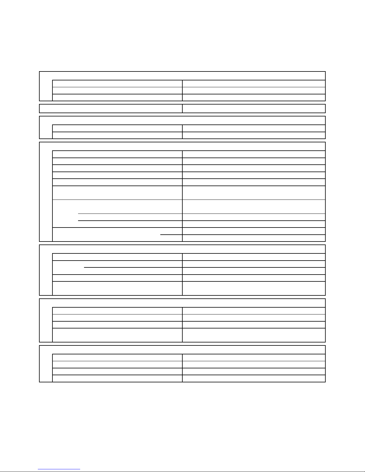
2-2. Major Component Specifications
2-2-1. Indoor Unit
Indoor Unit SAP-KRV96EHDS
(Ambient Temp. 25 °C)
MP24Z1
MP24Z1
Rating DC 5V
Coil Resistance Ohm Each Pair of Terminal : 70 +/- 7%
Panel Motor
Type Stepping Motor
Model MP24Z5
Flap Motor
Type Stepping Motor
Rating
Model
For Upper Flap
For Lower Flap
Coil Resistance Ohm
(Ambient Temp. 25 °C)
Each Pair of Terminal : 70 +/- 7%
DC 5V
Aluminum Plate Fin / Copper Tube
2
1.2
0.175 Face Area
Coil
Rows
Fin Pitch
Heat Exchanger Coil
m
2
mm
DATA SUBJECT TO CHANGE WITHOUT NOTICE.
Over-Heat Protection
Yes
Control PCB
Control Circuit Fuse
Controls
Part No.
Microprocessor
250V 3.15A
CB-KRV96EHDS
1 ... D85 / L551
RCS-6MHVPUSW4E
Cross-Flow
DC Motor
SIC-39CVL-D847-3-A ... 1
8
-
30
1,550 / 1,600
Internal Controller
Yes
-
-
Fan
Remote Control Unit
Q'ty ... Dia. and Length
Type
mm
Fan Motor
Nominal Output
Coil Resistance
Rough Measure RPM (Cool / Heat)
Type
Model ... Q'ty
No. of Poles
Safety Device
Type
Over- Current Protection
(Ambient Temp. 20 °C)
Run Capacitor Micro F
VAC
W
Ohm
8
Indoor Unit SAP-KRV126EHDS
(Ambient Temp. 25 °C)
MP24Z1
MP24Z1
Rating DC 5V
Coil Resistance Ohm Each Pair of Terminal : 70 +/- 7%
Panel Motor
Type Stepping Motor
Model MP24Z5
Flap Motor
Type Stepping Motor
Rating
Model
For Upper Flap
For Lower Flap
Coil Resistance Ohm
(Ambient Temp. 25 °C)
Each Pair of Terminal : 70 +/- 7%
DC 5V
Aluminum Plate Fin / Copper Tube
2
1.2
0.175 Face Area
Coil
Rows
Fin Pitch
Heat Exchanger Coil
m
2
mm
DATA SUBJECT TO CHANGE WITHOUT NOTICE.
Over-Heat Protection
Yes
Control PCB
Control Circuit Fuse
Controls
Part No.
Microprocessor
250V 3.15A
CB-KRV126EHDS
1 ... D85 / L551
RCS-6MHVPUSW4E
Cross-Flow
DC Motor
SIC-39CVL-D847-3-A ... 1
8
-
30
1,650 / 1,800
Internal Controller
Yes
-
-
Fan
Remote Control Unit
Q'ty ... Dia. and Length
Type
mm
Fan Motor
Nominal Output
Coil Resistance
Rough Measure RPM (Cool / Heat)
Type
Model ... Q'ty
No. of Poles
Safety Device
Type
Over- Current Protection
(Ambient Temp. 20 °C)
Run Capacitor Micro F
VAC
W
Ohm
9
Control PCB
Control Circuit Fuse
Controls
Part No.
Microprocessor
250V 20A
CB-CRV96EHDS
2-2-2. Outdoor Unit
Outdoor Unit SAP-CRV96EHDS
DATA SUBJECT TO CHANGE WITHOUT NOTICE.
CC
-
Micro F
VAC
External Finish Acrylic baked-on enamel finish
FV50S ... 350
-
Yes
-
Internal Controller
Yes
Aluminum Plate Fin / Copper Tube
2
1.4
Face Area
m
2
0.414
Coil
Rows
Fin Pitch mm
Heat Exchanger Coil
ARW35A8P60SY ... 1
Compressor Oil ... Amount
8
60
750 / 750
Ohm
DC Motor
Type
Compressor Model / Nominal Output
Compressor
Coil Resistance (Ambient Temp. 20 °C)
Ohm
DC Rotary (Hermetic)
C-1RVN68H0K / 675W
R - S : 0.632
S - T : 0.632
T - R : 0.632
CT (Peak current cut-off control)
Compressor Discharge Temp. Control
Operation cut-off control in abnormal ambient Temp.
Safety Device
Micro F
VAC
Run Capacitor
Crankcase Heater
Yes
Yes
Yes
-
-
-
1 ... D400
Fan
Propeller
Q'ty ... Dia. mm
Type
Type
Over- Current Protection
Over- Heat Protection
(Ambient Temp. 20 °C)
Fan Motor
Nominal Output
Coil Resistance
Safety Device
Rough Measure RPM (Cool / Heat)
Run Capacitor
Type
Model ... Q'ty
No. of Poles
W
10

Control PCB
Control Circuit Fuse
Controls
Part No.
Microprocessor
250V 20A
CB-CRV126EHDS
Outdoor Unit SAP-CRV126EHDS
DATA SUBJECT TO CHANGE WITHOUT NOTICE.
CC
-
Micro F
VAC
External Finish Acrylic baked-on enamel finish
FV50S ... 350
-
-
Internal Controller
Aluminum Plate Fin / Copper Tube
2
1.4
Face Area
m
2
0.414
Coil
Rows
Fin Pitch mm
Heat Exchanger Coil
ARW35A8P60SY ... 1
Compressor Oil ... Amount
8
60
750 / 750
Ohm
DC Motor
Type
Compressor Model / Nominal Output
Compressor
Coil Resistance (Ambient Temp. 20 °C)
Ohm
DC Rotary (Hermetic)
C-1RVN68H0K / 675W
R - S : 0.632
S - T : 0.632
T - R : 0.632
CT (Peak current cut-off control)
Compressor Discharge Temp. Control
Operation cut-off control in abnormal ambient Temp.
Safety Device
Micro F
VAC
Run Capacitor
Crankcase Heater
Yes
Yes
Yes
-
-
-
1 ... D400
Fan
Propeller
Q'ty ... Dia. mm
Type
Type
(Ambient Temp. 20 °C)
Fan Motor
Nominal Output
Coil Resistance
Safety Device
Rough Measure RPM (Cool / Heat)
Run Capacitor
Type
Model ... Q'ty
No. of Poles
W
Yes
Yes
Over- Current Protection
Over- Heat Protection
11
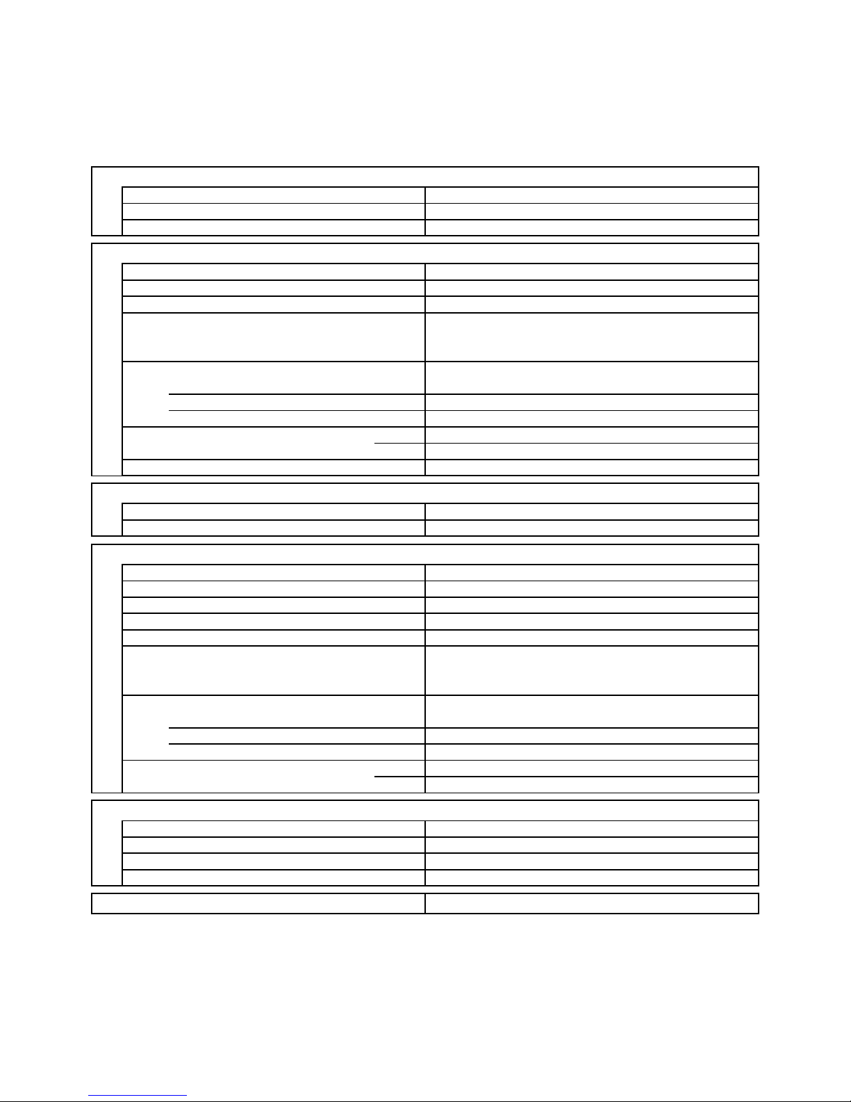
2-3. Other Component Specifications
Indoor Unit SAP-KRV96EHDS
SAP-KRV126EHDS
Outdoor Unit SAP-CRV96EHDS
SAP-CRV126EHDS
0
0102030405060708090
40
60
80
100
120
140
160
180
200
20
10
1
2
3
4
5
6
7
8
9
10
15 20 25 30 35 40
• Indoor air temp sensor
(Model:DTN-TKS319Y TH1)
• Humidity sensor
(Model:C10-M52R-SY2)
• Indoor heat exchanger sensor
(Model:DTN-TKS319Y TH2)
• Compressor temp sensor
(Model:DTN-TKS335B)
Resistance (k ohm)Resistance (k ohm)
Resistance (k ohm)
Temperature (°C)
Temperature (°C)
• Outdoor air temp sensor
(Model:1FA4V2E034000)
• Outdoor heat exchanger sensor
(Model:DTN-TKS334B)
40
35
30
25
20
15
10
5
0
-20-15-10-
50 5101520
Temperature (°C)Relative Humidity (%RH)
Resistance (k ohm)
30 35 40 45 50 55 60 65 70 75 80 85 90
1
10
100
1000
25 C
12
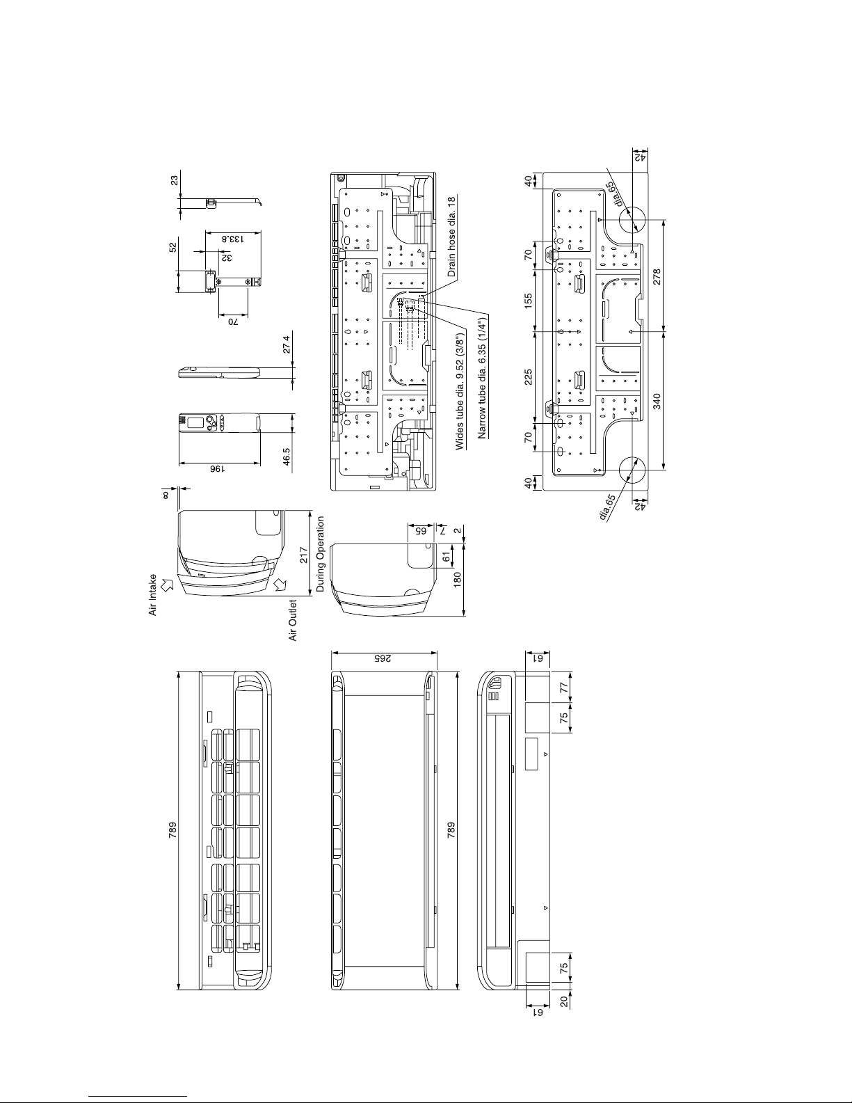
3. DIMENSIONAL DATA
Indoor Unit SAP-KRV96EHDS
SAP-KRV126EHDS
Unit: mm
13
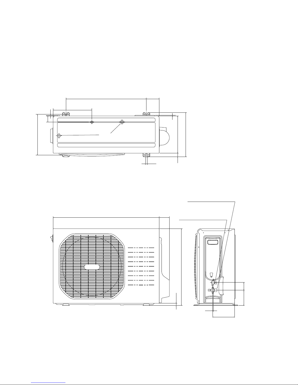
Outdoor Unit SAP-CRV96EHDS
SAP-CRV126EHDS
Unit: mm
790 72
Wide tube service valve
dia.9.52 (3/8")
ID:19
Narrow tube service valve
dia.6.35(1/4"
)
565
16
109 55
155
2
91
26525
46
290
315
608
309
12
5
3
14
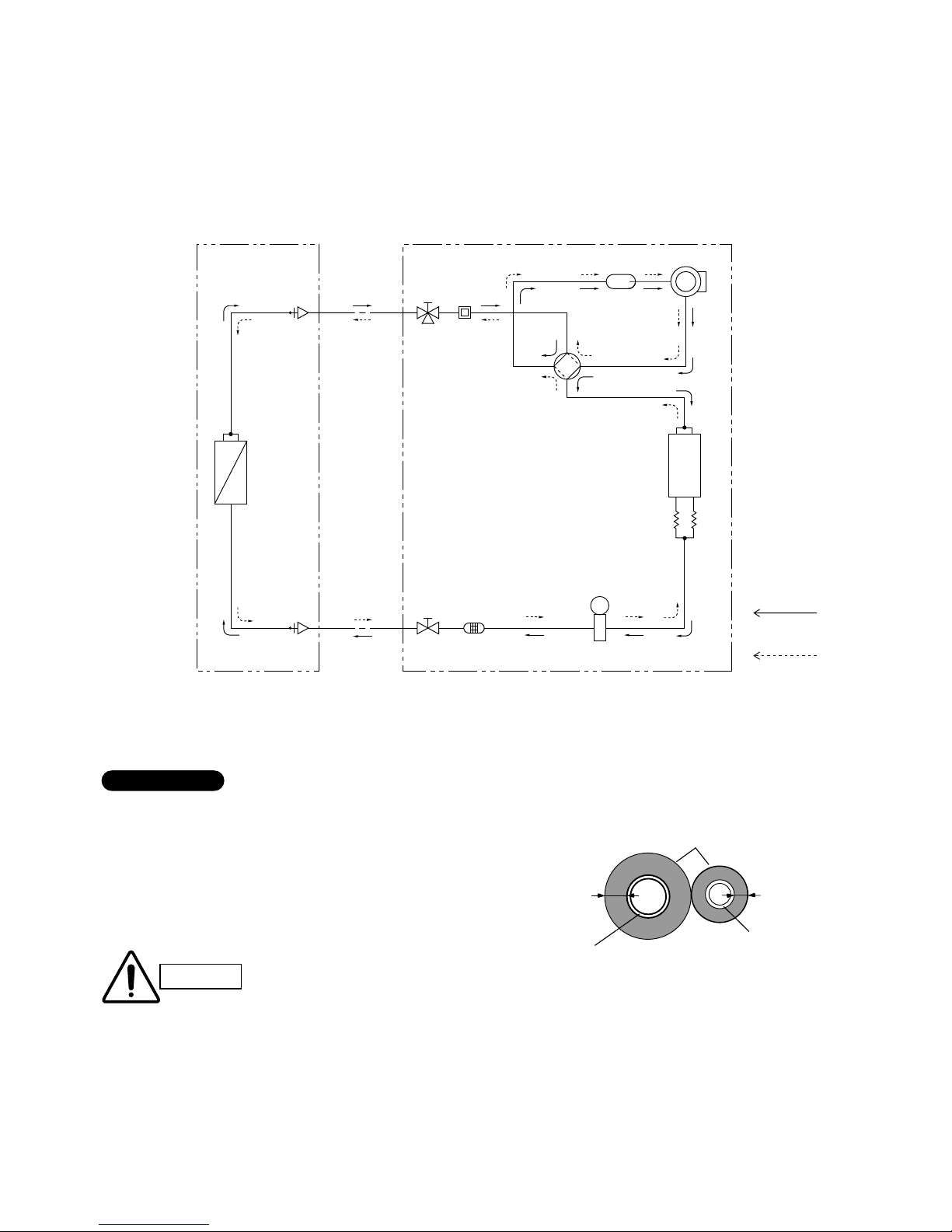
Compressor
4-way
valve
Accumulator
Wide tube
service
valve
Wide tube
O.D.
9.52 mm
(3/8 ")
Narrow
tube
service
valve
Narrow tube
O.D.
6.35 mm
(1/4")
Heat exchanger
Heat exchanger
Muffler
Capillary
tube for
split flow
Cooling cycle
(Defrosting cycle)
Heating cycle
Indoor unit Outdoor unit
Electric
expansion
valve
Strainer
M
4. REFRIGERANT FLOW DIAGRAM
4-1. Refrigerant Flow Diagram
Indoor Unit SAP-KRV96EHDS
SAP-KRV126EHDS
Outdoor Unit SAP-CRV96EHDS
SAP-CRV126EHDS
Insulation of Refrigerant Tubing
Because capillary tubing is used in the outdoor unit, both the
wide and narrow tubes of this air conditioner become cold. To
prevent heat loss and wet floors due to dripping of
condensation, both tubes must be well insulated with a
proper insulation material. The thickness of the insulation
should be a min. 8 mm.
After a tube has been insulated,
never try to bend it into a narrow
curve because it can cause the tube
to break or crack.
Wide tube
Thickness:
Min. 8 mm
Insulation
Narrow tube
Thickness:
Min. 8 mm
IMPORTANT
CAUTION
15
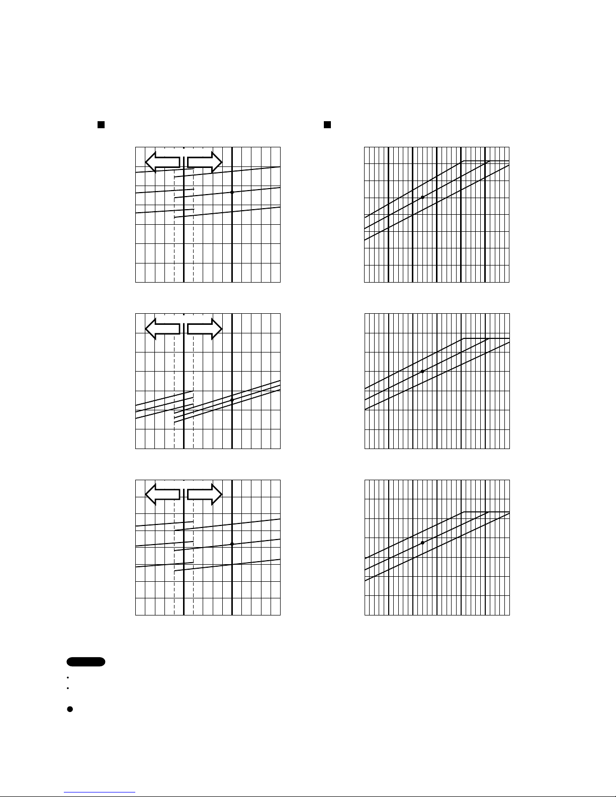
Indoor air temperature 20 °C D.B.
Outdoor air temperature 7 °C D.B. / 6 °C W.B.
Indoor air temperature 27 °C D.B. / 19 °C W.B.
Outdoor air temperature 35 °C D.B. / 24 °C W.B.
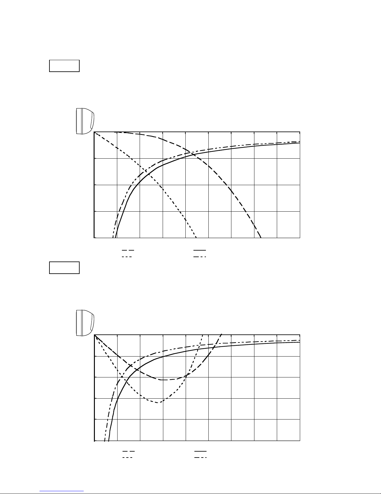
5. PERFORMANCE DATA
5-1. Temperature Charts
Indoor Unit SAP-KRV96EHDS
Outdoor Unit SAP-CRV96EHDS
Cooling Characteristics Heating Characteristics
Outdoor inlet air D.B. temp. (°C)
Outdoor inlet air D.B. temp. (°C) Outdoor inlet air D.B. temp. (°C)
Outdoor inlet air D.B. temp. (°C) Outdoor inlet air D.B. temp. (°C)
Operating current (A)
Operating current (A)
Indoor discharge air temperature (°C)
Indoor discharge air temperature (°C)
Outdoor inlet air D.B. temp. (°C)
Low pressure at wide tube service valve
MPaG (kgf/cm
2
G)
High pressure at wide tube service valve
MPaG (kgf/cm
2
G)
Check each performance value in test-run mode. Electrical performance values represent a combined indoor/outdoor value.
Overload prevention operates to protect the air conditioner when outdoor ambient temperature becomes extremely high in
heating mode. (Refer to "9-2. Overload prevention during heating.")
:Points of rating condition
Black dots in above charts indicate the following rating conditions.
NOTE
Cooling: Heating:
30 35 40
1.2
(12.2)
1.4
(14.2)
1.0
(10.2)
0.8
(8.2)
25
Outdoor fan speed
HighLow
27
°C
24
°C
Indoor Air Temp.30°C
27
°C
24
°C
Indoor Air Temp.30°C
25 30 35 40
4
5
3
2
Outdoor fan speed
HighLow
25 30 35 40
25
20
15
10
5
Outdoor fan speed
HighLow
-
50 510152025
3.5
(35.7)
3.0
(30.6)
2.5
(25.5)
2.0
(20.4)
1.5
(15.3)
-
50 510152025
2
5
4
3
-
50 510152025
55
50
45
40
35
30
25
20
20
°C
17
°C
Indoor Air Temp.23°C
20
°C
17
°C
Indoor Air Temp.23
°C
24
°C
Indoor Air Temp.30°C
27
°C
24
°C
Indoor Air Temp.30°C
27
°C
17
°C
Indoor Air Temp.23°C
20
°C
17
°C
Indoor Air Temp.23
°C
20
°C
27
°C
24°C
Indoor Air Temp.30°C
27
°C
24
°C
Indoor Air Temp.30
°C
20
°C
17
°C
Indoor Air Temp.23°C
20
°C
17
°C
Indoor Air Temp.23
°C
16
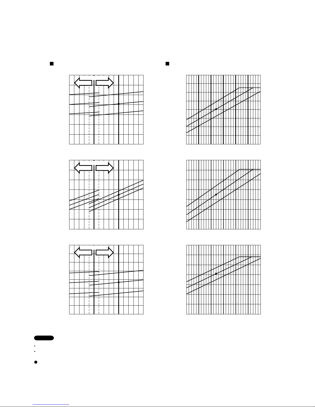
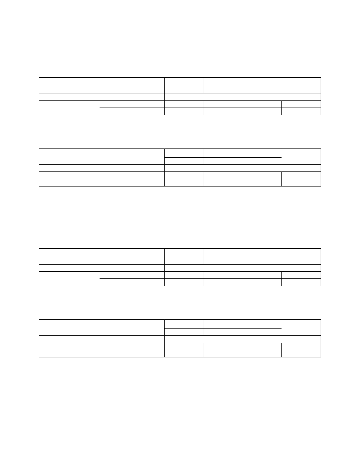
Indoor air temperature 20 °C D.B.
Outdoor air temperature 7 °C D.B. / 6 °C W.B.
Indoor air temperature 27 °C D.B. / 19 °C W.B.
Outdoor air temperature 35 °C D.B. / 24 °C W.B.
Indoor Unit SAP-KRV126EHDS
Outdoor Unit SAP-CRV126EHDS
Check each performance value in test-run mode. Electrical performance values represent a combined indoor/outdoor value.
Overload prevention operates to protect the air conditioner when outdoor ambient temperature becomes extremely high in
heating mode. (Refer to "9-2. Overload prevention during heating.")
:Points of rating condition
Black dots in above charts indicate the following rating conditions.
Cooling Characteristics Heating Characteristics
NOTE
Cooling: Heating:
Outdoor inlet air D.B. temp. (°C)
Outdoor inlet air D.B. temp. (°C) Outdoor inlet air D.B. temp. (°C)
Outdoor inlet air D.B. temp. (°C) Outdoor inlet air D.B. temp. (°C)
Operating current (A)
Operating current (A)
Indoor discharge air temperature (°C)
Indoor discharge air temperature (°C)
Outdoor inlet air D.B. temp. (°C)
Low pressure at wide tube service valve
MPaG (kgf/cm
2
G)
High pressure at wide tube service valve
MPaG (kgf/cm
2
G)
30 35 40
1.2
(12.2)
1.4
(14.2)
1.0
(10.2)
0.8
(8.2)
25
Outdoor fan speed
HighLow
27
°C
24
°C
Indoor Air Temp.30°C
27
°C
24
°C
Indoor Air Temp.30
°C
25 30 35 40
5
6
4
3
Outdoor fan speed
HighLow
25 30 35 40
25
20
15
10
5
Outdoor fan speed
HighLow
-
50 510152025
4.0
(40.8)
3.5
(35.7)
3.0
(30.6)
2.5
(25.5)
2.0
(20.4)
-
50 510152025
4
7
6
5
-
50 510152025
55
50
45
40
35
30
25
20
20
°C
17
°C
Indoor Air Temp.23°C
20
°C
17
°C
Indoor Air Temp.23
°C
24
°C
Indoor Air Temp.30°C
27
°C
24
°C
Indoor Air Temp.30
°C
27
°C
17
°C
Indoor Air Temp.23°C
20
°C
17
°C
Indoor Air Temp.23°C
20
°C
27
°C
24
°C
Indoor Air Temp.30°C
27
°C
24
°C
Indoor Air Temp.30
°C
20
°C
17
°C
Indoor Air Temp.23°C
20
°C
17
°C
Indoor Air Temp.23
°C
17
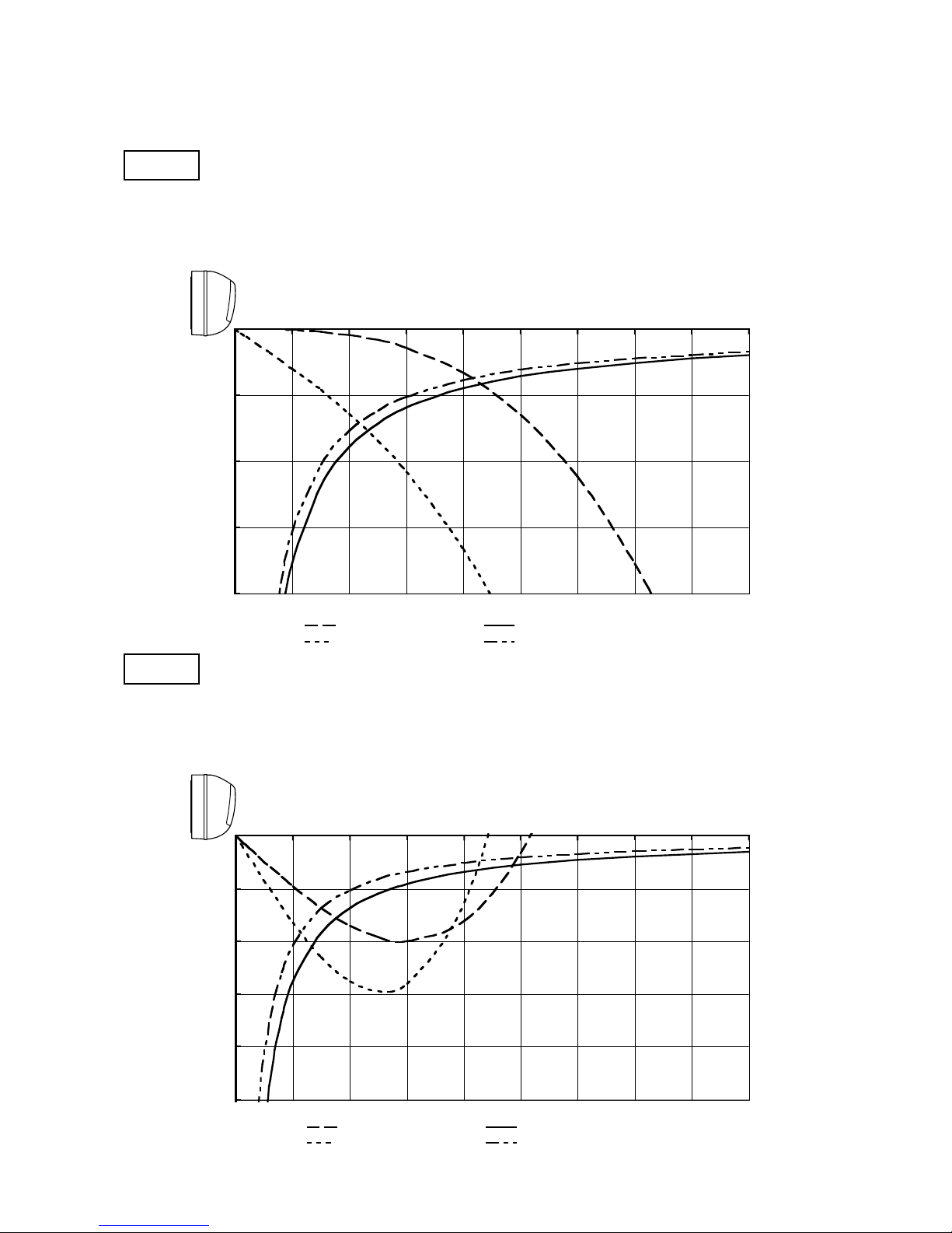
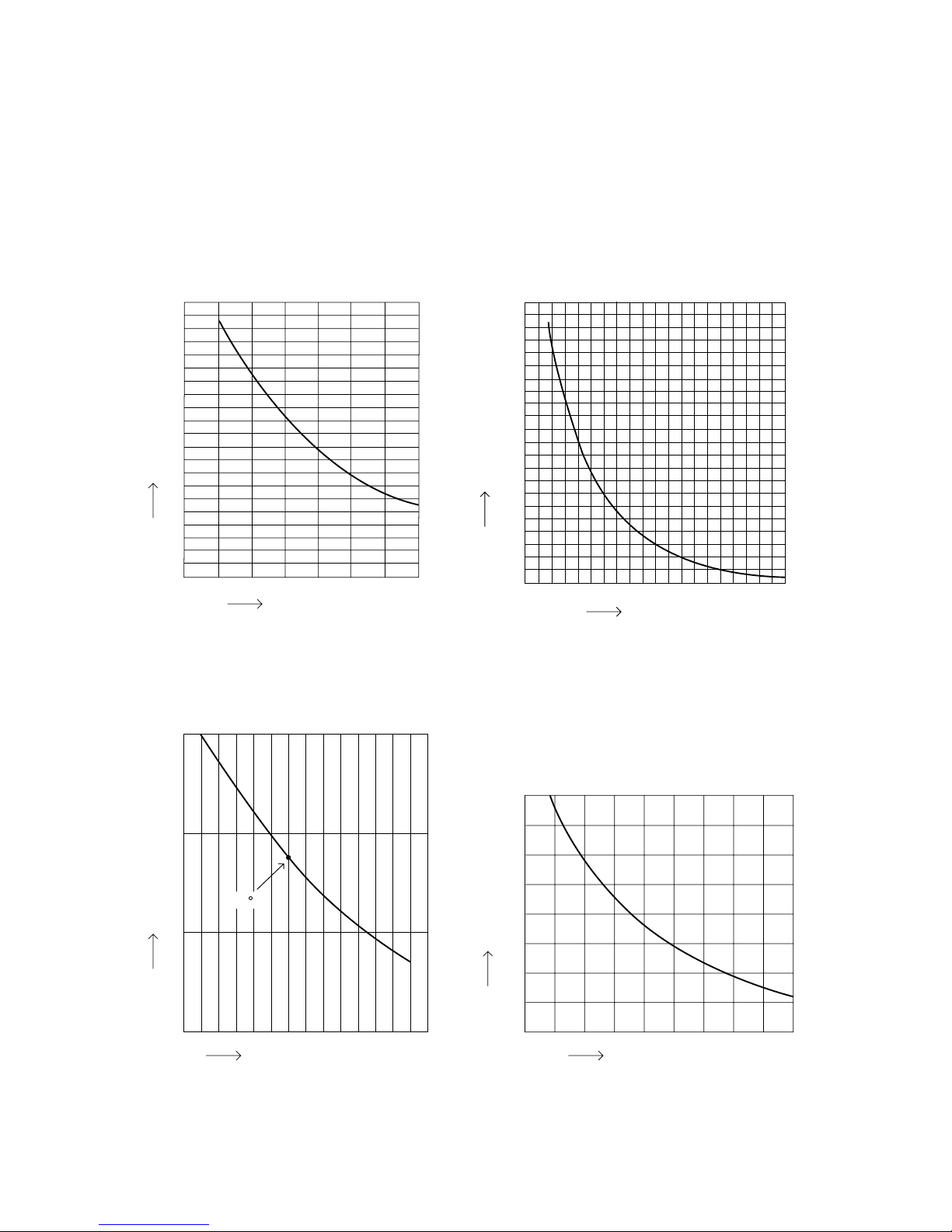
Horizontal distance (m)
Axis air velocity (m/s)
Vertical distance (m)
Room air temp. : 20 °C
Fan speed : High
Heating
Horizontal distance (m)
Axis air velocity (m/s)
Vertical distance (m)
Room air temp. : 27 °C
Fan speed : High
Cooling
: Flap angle 0° , : Axis air velocity 0°
: Flap angle 30°, : Axis air velocity 30°
: Flap angle 45°,
: Axis air velocity 45°
: Flap angle 60°,
: Axis air velocity 60°
5-2. Air Throw Distance Charts
Indoor Unit SAP-KRV96EHDS
0
1
2
3
4
0123456789
0
1
2
3
4
5
0123456789
18
Horizontal distance (m)
Axis air velocity (m/s)
Vertical distance (m)
Room air temp. : 20 °C
Fan speed : High
Heating
Horizontal distance (m)
Axis air velocity (m/s)
Vertical distance (m)
Room air temp. : 27 °C
Fan speed : High
Cooling
: Flap angle 0°, : Axis air velocity 0°
: Flap angle 30°, : Axis air velocity 30°
: Flap angle 45°, : Axis air velocity 45°
: Flap angle 60°, : Axis air velocity 60°
Indoor Unit SAP-KRV126EHDS
0
1
2
3
4
0123456789
0
1
2
3
4
5
0123456789
19
6. ELECTRICAL DATA
6-1. Electrical Characteristics
Indoor Unit SAP-KRV96EHDS
Outdoor Unit SAP-CRV96EHDS
Indoor Unit Outdoor Unit Complete Unit
Fan Motor Fan Motor + Compressor
Performance at 230V Single-phase 50Hz
Rating conditions Running amp. A 0.34
Power input W 30
2.92
600
Rating conditions: Indoor air temperature: 27 °C D.B. / 19 °C W.B.
Outdoor air temperature: 35 °C D.B.
Rating conditions: Indoor air temperature 20 °C D.B.
Outdoor air temperature 7 °C D.B. / 6 °C W.B.
Rating conditions: Indoor air temperature: 27 °C D.B. / 19 °C W.B.
Outdoor air temperature: 35 °C D.B.
Rating conditions: Indoor air temperature: 20 °C D.B.
Outdoor air temperature: 7 °C D.B. / 6 °C W.B.
Heating
Cooling
3.26
630
Indoor Unit Outdoor Unit Complete Unit
Fan Motor Fan Motor + Compressor
Performance at 230V Single-phase 50Hz
Rating conditions Running amp. A 0.35
Power input W 32
3.68
803
4.03
835
Indoor Unit SAP-KRV126EHDS
Outdoor Unit SAP-CRV126EHDS
Indoor Unit Outdoor Unit Complete Unit
Fan Motor Fan Motor + Compressor
Performance at 230V Single-phase 50Hz
Rating conditions Running amp. A 0.36
Power input W 33
4.43
992
Heating
Cooling
4.79
1,025
Indoor Unit Outdoor Unit Complete Unit
Fan Motor Fan Motor + Compressor
Performance at 230V Single-phase 50Hz
Rating conditions Running amp. A 0.40
Power input W 39
5.37
1,221
5.77
1,260
20
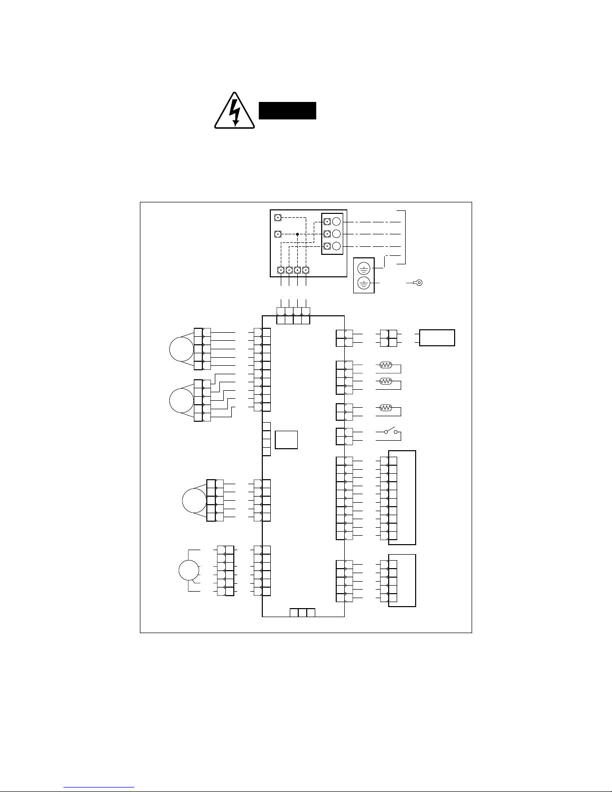
6-2. Electric Wiring Diagrams
Indoor Unit SAP-KRV96EHDS
SAP-KRV126EHDS
WARNING
To avoid electrical shock hazard, be sure to
disconnect power before checking, servicing
and/or cleaning any electrical parts.
1
1
1133557
7
2
2
3
3
4
1
2
3
4
4
5
5
1
1
2
2
3
3
4
4
5
5
1
1
2
2
3
3
4
4
5
5
WHT
GRY
1
1
2
2
1
1
2
2
1
1
2
2
3
3
4
4
RED
BLK
11
2
2
1 1
2
2
WHT
GRY
33
4
4
3 3
4
4
GRY
GRY
55
6
6
5 5
6
6
GRY
GRY
77
8
9
10
8
9
10
7 7
8
9
10
8
9
10
GRY
GRY
GRY
GRY
RED
BLK
GRY
GRY
GRY
6
6
7
7
8
8
9
9
10
10
WHT
BLU
BLU
BLU
BLU
CONTROLLER
FLAP1
FLAP MOTOR
FLAP1
(WHT)
ELEC-JB1
(WHT)
UV
(RED)
EARTH PLATE
TERMINAL
BASE
JOINT BOX
EVAPORATOR
TO OUTDOOR UNIT
ROOM
/COIL
(WHT)
HUM
(RED)
SW2
(BLU)
LAMP
(WHT)
SW1
(WHT)
DC OUT
(WHT)
(WHT)
(WHT)
(RED)
THERMISTOR
(ROOM)
THERMISTOR
(COIL)
THERMISTOR
(HUM)
PANEL SW
UV UNIT
IND LAMP
ASSY
SW ASSY
PANEL
(WHT)
DCM
(BLU)
(WHT)
HA
JEM-A
PANEL MOTOR
DC FAN MOTOR
(UPPER)
FLAP MOTOR
(LOWER)
(WHT)(WHT)
(WHT)(RED)
(WHT)
(BLU)
11
2
2
3
3
44
5
5
1 1
2
2
3
3
4 4
5
5
WHT
GRY
GRY
GRY
GRY
FLAP3
11
2
2
3
3
44
5
5
RED
BLK
WHT
YEL
6
1 2 3
6
11
2
2
3
3
44
5
5
6
6
BLU
RED
BLK
WHT
YEL
BLU
FM
FLAP2
1
2
3
BRN
RED
ORG
YRL
BLK
BLK
1
1
2
2
BLK
BLK
1 1
2
2
WHT
BLK
ORG
ORG
11
2
2
1 1
2
2
WHT
BLU
33
4
4
3 3
4
4
BLU
BLU
555 5
BLU
GRN/YEL
8FA2-5250-07400-1
21
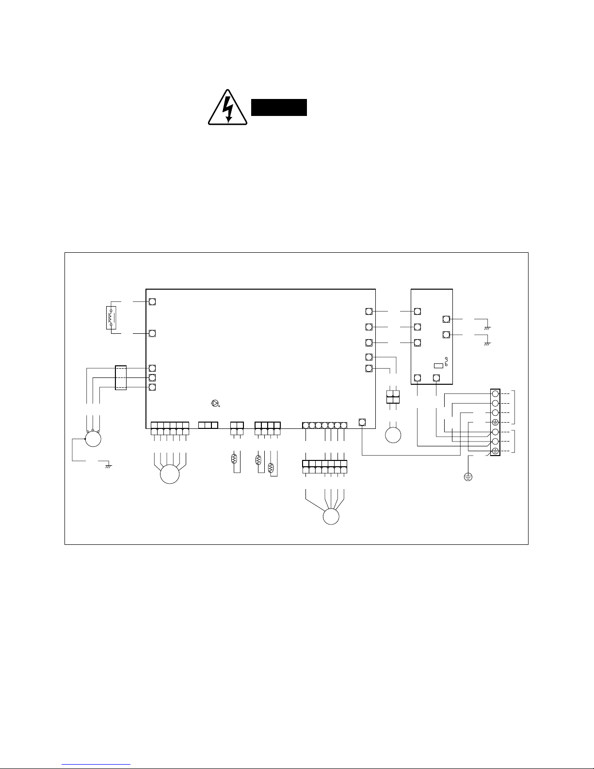
Outdoor Unit SAP-CRV96EHDS
SAP-CRV126EHDS
WARNING
To avoid electrical shock hazard, be sure to
disconnect power before checking, servicing
and/or cleaning any electrical parts.
CONTROLLER
U
L1
L2
V
W
ACIN1
E
E1
IN2 IN1
OUT1
OUT2
SICOM
GND
GND
TERMINAL
PLATE
TO INDOOR UNIT
POWER
SUPPLY
AC250V
20V
ACIN2
COM
RV0
RV1
2P-CONNECTOR (WHT)
NOISE FILTER
COMPRESSOR
7P-CONNECTOR
THERMISTOR
COIL
THERMISTOR
OUTDDOR
CM
COMPRESSOR
MOTOR
FERRITE
CORE
REACTOR
RT
S
THERMISTOR
4WAY VALVE
COIL
FAN MOTOR
RV
FM
MV
MAGNETIC COIL
SI
(WHT)
T-RUN/TEST
(BLK)
MV
(WHT)
OUTDDOR
(WHT)
COIL/COMP
(WHT)
DCFM
TLC
11 2 3
122
11223344556
6
1122334455667
7
1122334
4
W
W
W
W
1 2 3 4 5 6 7
W
W
W
W
W
W
W W
W
W
W
W
W
W
1
2
3
L
N
BLK
GRN
GRN
WHT
WHT
RED
GRN
GRN
WHT
BLK
BLK
WHT
BLU
BLU
BLU
BLK
BLK
BLK
BLK
BLU
GRN
WHT
RED
(PINK)
ORG
YEL
YEL
YEL
BLU
ORG
RED
GRY
WHT
YEL
BLK
WHT
BLK
RED
BLU
YEL
WHT
BLK
RED
BLU
YEL
8FA2-5250-09900-1
112
2
22
WARNING
7. INSTALLATION INSTRUCTIONS
7-1. Installation Site Selection
7-1-1. Indoor Unit
To prevent abnormal heat
generation and the possibility
of fire, do not place obstacles,
enclosures and grilles in front
of or surrounding the air
conditioner in a way that may
block air flow.
For stable operation of
the air conditioner, do not
install wall-mounted type
indoor units less than
1.5 m from floor level.
AVOID:
direct sunlight.
nearby heat sources that may affect performance of
the unit.
areas where leakage of flammable gas may be
expected.
places where large amounts of oil mist exist.
DO:
select an appropriate position from which every corner
of the room can be uniformly cooled. (High on a wall
is best.)
select a location that will hold the weight of the unit.
select a location where tubing and drain hose have
the shortest run to the outside.
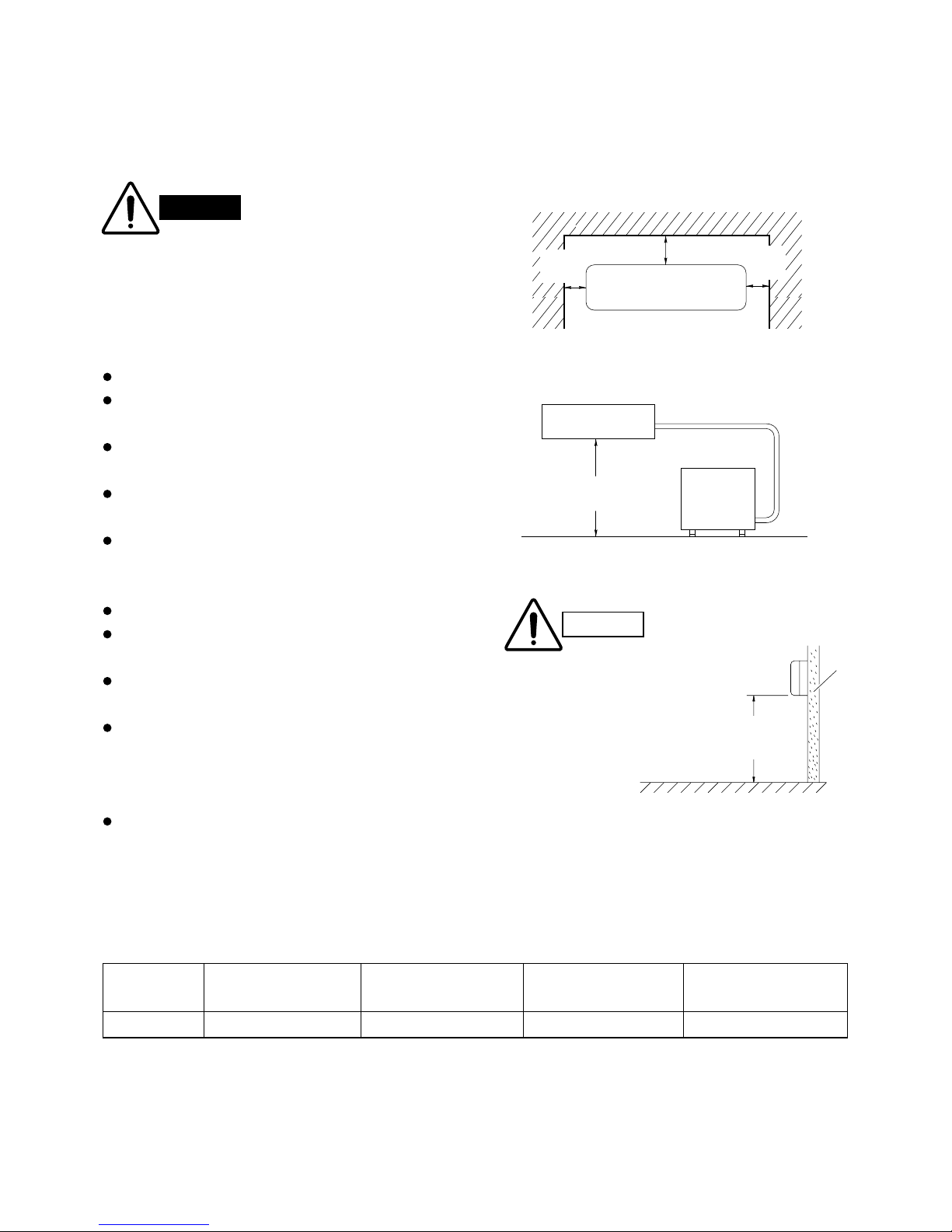
allow room for operation and maintenance as well as
unrestricted air flow around the unit. (Fig. 1)
install the unit within the maximum elevation
difference (H) above or below the outdoor unit and
within a total tubing length (L) from the outdoor unit as
detailed in Table 1 and Fig. 2.
Install the indoor unit more than 1 meter away from
any antenna or power lines or connecting wires used
for television, radio, telephone, security system, or
intercom. Electrical noise from any of these sources
may affect operation.
Table 1
Model
KRV96 / 126
* If total tubing length becomes 7.5 to 15 m, charge additional refrigerant (R410A) by 15 g/m.
No additional charge of compressor oil is necessary.
Max. Allowable Tubing
Length at Shipment
(m)
7.5
Limit of Tubing
Length (L)
(m)
15
Limit of Elevation
Difference (H)
(m)
10
Required Amount of
Additional Refrigerant
(g/m)*
15
5 cm
min.
5 cm
min.
15 cm min.
Front View
INDOOR
UNIT
Tubing length (L)
OUTDOOR
UNIT
Elevation
difference (H)
CAUTION
Indoor unit
Floor level
Wall
Minimum height
from floor level
1.5 m
Fig. 1
Fig. 2
Fig. 3
23
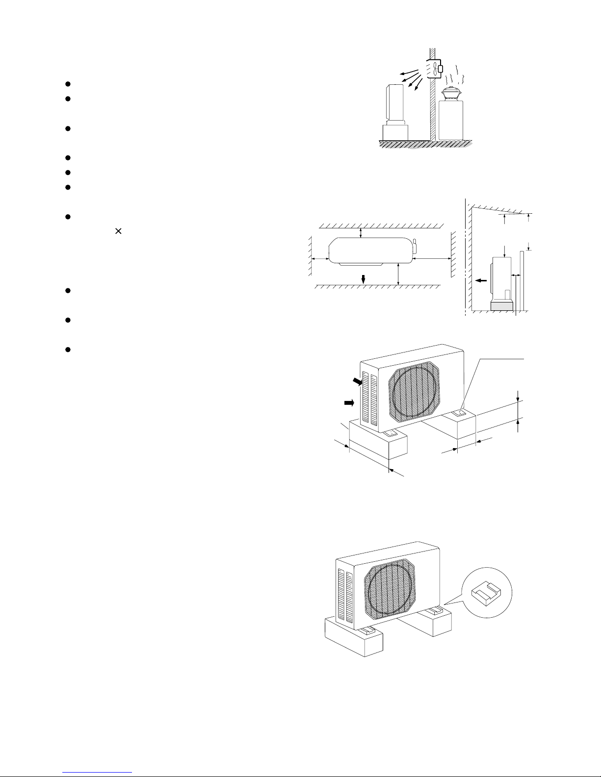
Cushion rubber
Air intake Min. 5 cm
Air discharge
Min.
5 cm
Min. 5cm
Air intake
Min.
20 cm
Valve
side
Min.
25 cm
Outdoor unit
Hot air
Heat source
Exhaust fan
NO
Min.
2 m
Min.
2 m
Ground
Obstacle
Obstacle above
Air discharge
Air intake
Concrete
or equal
About 10 cm
Min. 10 cm
Anchor bolts
(4 pcs.)
About 40 cm
7-1-2. Outdoor Unit
Fig. 5a
Fig. 5b
Fig. 4
AVOID:
heat sources, exhaust fans, etc. (Fig. 4)
damp, humid or uneven locations.
DO:
position the outdoor unit in a protected location
where snow will not blow into it.
choose a place as cool as possible.
choose a place that is well ventilated.
allow enough room around the unit for air intake/
exhaust and possible maintenance. (Fig. 5a)
provide a solid base (level concrete pad, concrete
block, 10 40 cm beams or equal), a minimum of
10 cm above ground level to reduce humidity and
protect the unit against possible water damage and
decreased service life. (Fig. 5a)
Install cushion rubber under unit's feet to reduce
vibration and noise. (Fig. 5b)
use lug bolts or equal to bolt down unit, reducing
vibration and noise.
Install in a location where no antenna of a
television or radio exists within 3 meters.
24
 Loading...