

Sanyo SAP-KMRV124EH, SAP-KMRV96EH, SAP-KMRV94EH, SAP-KMRV76EH, SAP-KMRV126EH Installation Instructions Manual
...
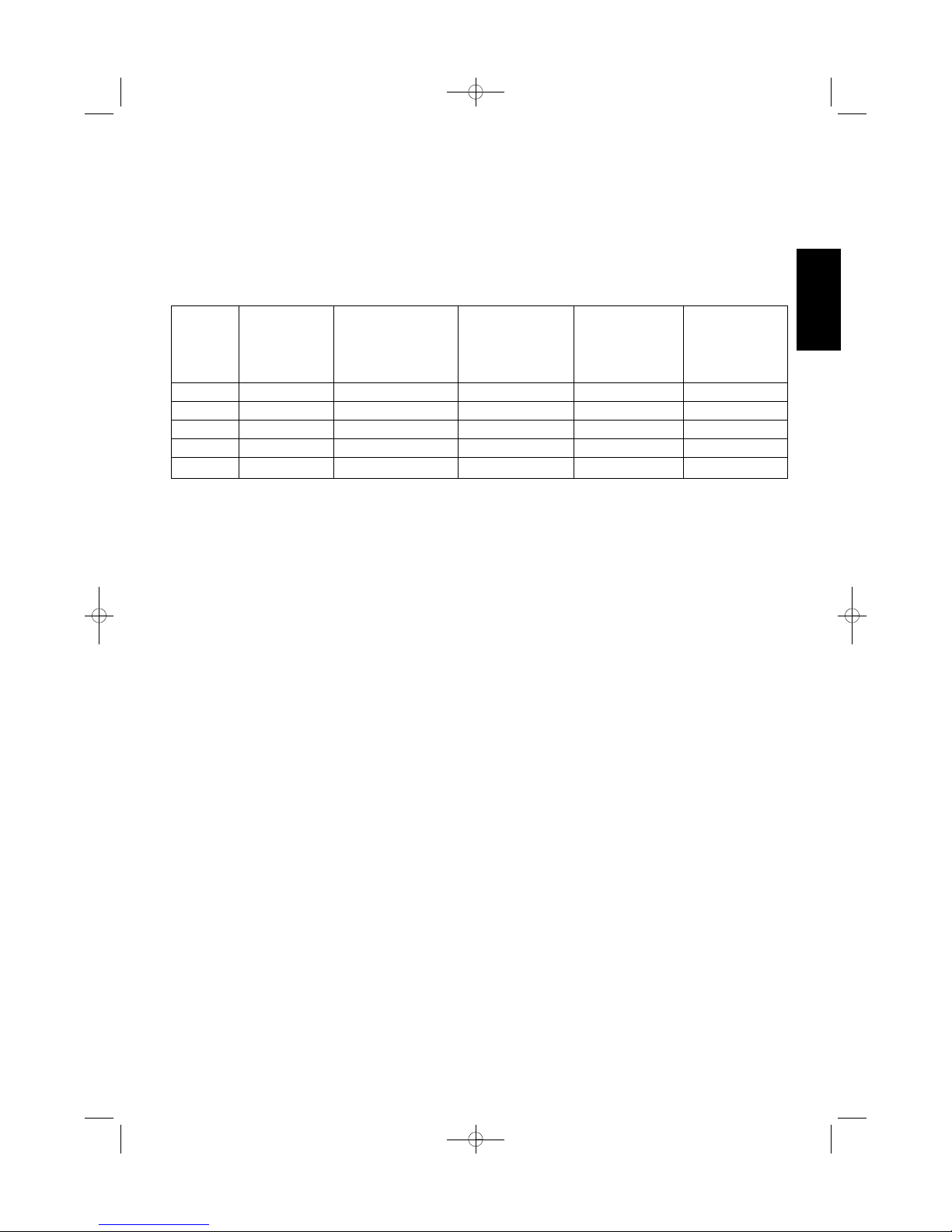
Model Combinations
Combine indoor and outdoor units only as listed
below.
Indoor Unit Outdoor Unit
Power Source:
50 Hz, single-phase, 220 – 240 VAC
Combinations of indoor and outdoor units
Connect indoor and outdoor units only in the
combinations listed in the catalog or installation
manual.
Connecting any other model may result in
operation failure and system damage.
CAUTION
Español
Français Deutsch Italiano
Português
EEÏÏÏÏËËÓÓÈÈÎο¿
English
85264190441000 © SANYO 2008 SANYO Electric Co., Ltd.
Osaka, Japan
Contents
Page
IMPORTANT!
Please Read Before Starting .................................. 2
1. GENERAL .......................................................... 3
1-1. Tools Required for Installation (not supplied)
1-2. Accessories Supplied with Unit
1-3. Optional Copper Tubing Kit
1-4. Type of Copper Tube and Insulation Material
1-5. Additional Materials Required for Installation
2. INSTALLATION SITE SELECTION ................... 4
2-1. Indoor Unit
2-2. Embedding the Tubing and Wiring
3. HOW TO INSTALL THE INDOOR UNIT ............ 6
3-1. Remove the Rear Panel from the Unit
3-2. Make a Hole
3-3. Install the Rear Panel on the Wall
3-4. Removing and Installing the Grille
3-5. Shape the Indoor Side Tubing
3-6. Wiring Instructions
3-7. Wiring Instructions for Inter-unit Connections
3-8. Mounting
3-9. Drain Hose
4. MULTIPLE SWITCH ON THE REMOTE
CONTROL UNIT INDOOR UNIT TYPES
(SAP-KRV184EH, KRV244EH)
(SAP-KRV186EH, KRV246EH)
(SAP-KRV96EHDS) .......................................... 19
5. HOW TO TEST RUN THE AIR CONDITIONER ... 20
6. REMOTE CONTROL UNIT INSTALLATION
POSITION ......................................................... 22
6-1. Mounting on a Wall
7. ADDRESS SWITCH.......................................... 23
7-1. Address Setting of the Remote
Control Unit
8. CONNECTING A HOME AUTOMATION
DEVICE.............................................................. 24
9. INSTALLATION CHECK SHEET...................... 24
INSTALLATION INSTRUCTIONS
– Inverter Split System Air Conditioner –
COOL/DRY/HEAT Model
This air conditioner uses the new refrigerant R410A.
Be sure to read the yellow instruction sheet
attached to the outdoor unit for models using the
new refrigerant R410A.
The illustrations are based on the typical appearance
of a standard model. Consequently, the shape may
differ from that of the air conditioner that you are
installing.
NOTE
For Indoor Unit
SAP-KMRV74EH
SAP-KMRV94EH
SAP-KMRV124EH
SAP-KMRV76EH
SAP-KMRV96EH
SAP-KMRV126EH
SAP-KRV184EH
SAP-KRV244EH
SAP-KRV186EH
SAP-KRV246EH
SAP-KRV96EHDS
SAP-CMRV1426EH
SAP-CMRV1926EH
SAP-CMRV1936EH
SAP-CMRV2446EH
SAP-CMRV3146EH
SAP-CMRV1426EH
SAP-CMRV1926EH
SAP-CMRV1936EH
07-370 CMRV3146EH_IU ENG 2/6/08 1:31 PM Page a
2
English
IMPORTANT!
Please Read Before Starting
This air conditioning system meets strict safety and operating standards. As the installer or service person, it is an
important part of your job to install or service the system
so it operates safely and efficiently.
For safe installation and trouble-free operation, you
must:
G
Carefully read this instruction booklet before beginning.
G
Follow each installation or repair step exactly as
shown.
G
Observe all local, state, and national electrical codes.
G
Pay close attention to all warning and caution notices
given in this manual.
This symbol refers to a hazard
or unsafe practice which can
result in severe personal injury
or death.
This symbol refers to a hazard
or unsafe practice which can
result in personal injury or
product or property damage.
If Necessary, Get Help
These instructions are all you need for most installation
sites and maintenance conditions. If you require help for
a special problem, contact our sales/service outlet or
your certified dealer for additional instructions.
In Case of Improper Installation
The manufacturer shall in no way be responsible for
improper installation or maintenance service, including
failure to follow the instructions in this document.
SPECIAL PRECAUTIONS
When Wiring
ELECTRICAL SHOCK CAN CAUSE
SEVERE PERSONAL INJURY OR DEATH.
ONLY A QUALIFIED, EXPERIENCED
ELECTRICIAN SHOULD ATTEMPT TO
WIRE THIS SYSTEM.
• Do not supply power to the unit until all wiring and tub-
ing are completed or reconnected and checked.
• Highly dangerous electrical voltages are used in this
system. Carefully refer to the wiring diagram and these
instructions when wiring. Improper connections and
inadequate grounding can cause accidental injury or
death.
• Ground the unit following local electrical codes.
• Connect all wiring tightly. Loose wiring may cause
overheating at connection points and a possible fire
hazard.
• Install a protective leakage breaker depending on the
installation location (especially a damp or humid location). If a leakage breaker is not installed, electric
shock can occur.
When Transporting
Be careful when picking up and moving the indoor and
outdoor units. Get a partner to help, and bend your knees
when lifting to reduce strain on your back. Sharp edges or
thin aluminum fins on the air conditioner can cut your fingers.
When Installing…
…In a Ceiling or Wall
Make sure the ceiling/wall is strong enough to hold the
unit’s weight. It may be necessary to construct a strong
wood or metal frame to provide added support.
…In a Room
Properly insulate any tubing run inside a room to prevent
“sweating” that can cause dripping and water damage to
walls and floors.
…In Moist or Uneven Locations
Use a raised concrete pad or concrete blocks to provide
a solid, level foundation for the outdoor unit. This prevents water damage and abnormal vibration.
When Connecting Refrigerant Tubing
• Do not add any refrigerant, air, or substance into the
refrigeration circuit other than the designated refrigerant (R410A). Adding anything other than the specified
refrigerant may cause the pressure to rise excessively
in the refrigeration circuit, rupturing the circuit and
causing injury or damage.
• Use all-new tubing and flare nuts to make the tubing
connections. Using any previous parts (from R22based systems) may result in damage to the equipment, and may lead to the refrigeration circuit rupturing, causing a serious accident.
• Apply refrigerant lubricant to the matching surfaces of
the flare and union tubes before connecting them, then
tighten the nut with a torque wrench for a leak-free
connection.
• Check carefully for leaks before starting the test run.
When Servicing
• Turn the power OFF at the main power box (mains)
before opening the unit to check or repair electrical
parts and wiring.
• Keep your fingers and clothing away from any moving
parts.
• Clean up the site after you finish, remembering to
check that no metal scraps or bits of wiring have been
left inside the unit being serviced.
Others
• Ventilate any enclosed areas when installing or testing
the refrigeration system. Escaped refrigerant gas, on
contact with fire or heat, can produce dangerously
toxic gas.
• Confirm upon completing installation that no refrigerant
gas is leaking. If escaped gas comes in contact with a
stove, gas water heater, electric room heater or other
heat source, it can produce dangerously toxic gas.
WARNING
WARNING
CAUTION
CAUTION
07-370 CMRV3146EH_IU ENG 2/6/08 1:31 PM Page 2
3
English
1. General
This booklet briefly outlines where and how to install
the air conditioning system. Please read over the
entire set of instructions for the indoor and outdoor
units and make sure all accessory parts listed are with
the system before beginning.
1-1. Tools Required for Installation (not supplied)
1. Standard screwdriver
2. Phillips head screwdriver
3. Knife or wire stripper
4. Tape measure
5. Carpenter’s level
6. Sabre saw or key hole saw
7. Hacksaw
8. Core bits
9. Hammer
10. Drill
11. Tube cutter
12. Tube flaring tool
13. Torque wrench
14. Adjustable wrench
15. Reamer (for deburring)
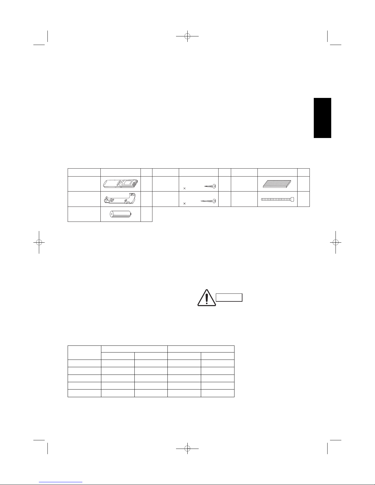
1-2. Accessories Supplied with Unit
Table 1
1-3. Optional Copper Tubing Kit
Copper tubing for connecting the outdoor unit to the
indoor unit is available in kits which contain the narrow
and wide tubing, fittings and insulation. Consult your
nearest sales outlet or Air Conditioner workshop.
1-4. Type of Copper Tube and Insulation Material
If you wish to purchase these materials separately
from a local source, you will need:
1. Deoxidized annealed copper tube for refrigerant
tubing as detailed in Table 2.
Cut each tube to the appropriate lengths +30 cm
to 40 cm to dampen vibration between units.
Table 2
2. Foamed polyethylene insulation for the specified
copper tubes as required to precise length of tubing. Wall thickness of the insulation should be not
less than 8 mm.
3. Use insulated copper wire for field wiring. Wire
size varies with the total length of wiring. Refer to
3-6. Wiring Instructions for details.
Parts Figure
1
1
2
AAA alkaline
battery
Remote
control unit
Remote control
unit holder
Parts Figure
Tapping
screw
Clamp**
Tapping
screw
Truss-head
Phillips
4 30 mm
Truss-head
Phillips
4
16 mm
2
8
Air clean
filter*
2
1
Parts Figure
Packed in the indoor unit.
* 1 only for KRV96.
** Not applicable for KRV96.
Q’ty Q’ty Q’ty
CAUTION
Check local electrical codes
and regulations before
obtaining wire. Also, check
any specified instructions or
limitations.
Model
Narrow Tube Wide Tube
Outer Dia. Thickness Outer Dia. Thickness
KMRV74/94/124 6.35 mm 0.8 mm 9.52 mm 0.8 mm
KMRV76/96/126 6.35 mm 0.8 mm 9.52 mm 0.8 mm
KRV96 6.35 mm 0.8 mm 9.52 mm 0.8 mm
KRV184/186 6.35 mm 0.8 mm 12.70 mm 0.8 mm
KRV244/246 6.35 mm 0.8 mm 15.88 mm 1.0 mm
07-370 CMRV3146EH_IU ENG 2/6/08 1:31 PM Page 3
4
English
1-5. Additional Materials Required for Installation
1. Refrigeration (armored) tape
2. Insulated staples or clamps for connecting wire
(See local codes)
3. Putty
4. Refrigeration lubricant
5. Clamps or saddles to secure refrigerant tubing
2. Installation Site Selection
2-1. Indoor Unit
AVOID:
G direct sunlight.
G nearby heat sources that may affect performance of the
unit.
G areas where leakage of flammable gas may be expected.
G placing or allowing any obstructions near the Air
Conditioner inlet or outlet.
G installing in rooms that contain instant-on (rapid-start)
fluorescent lamps. (These may prevent the Air Conditioner
from receiving signals.)
G places where large amounts of oil mist exist.
G installing in locations where there are devices that
generate high-frequency emissions.
DO:
G select an appropriate position from which every corner of
the room can be uniformly cooled. (High on a wall is best.)
G select a location that will hold the weight of the unit.
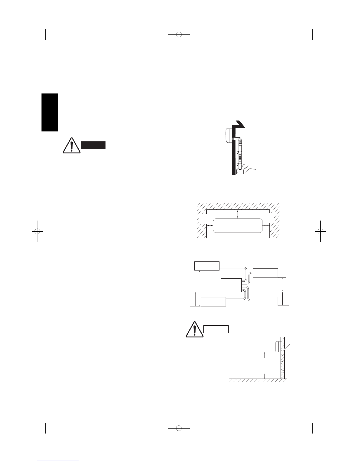
G select a location where tubing and drain hose have the
shortest run to the outside. (Fig. 1)
G allow room for operation and maintenance as well as
unrestricted air flow around the unit. (Fig. 2)
G install the unit within the maximum elevation difference
(H1, H2, H3, H4) above or below the outdoor unit and
within a total tubing length (L1+L2, L1+L2+L3,
L1+L2+L3+L4) from the outdoor unit as detailed in Table 3
and Fig. 3a.
Drain hose
Indoor unit
Outside drainage
Fig. 1
5 cm
min.
5 cm
min.
15 cm min.
Front View
Fig. 2
INDOOR
UNIT (1)
INDOOR
UNIT (4)
INDOOR
UNIT (3)
INDOOR
UNIT (2)
Tubing length (L1)
L2
L3
L4
H2
H3
H4
OUTDOOR
UNIT
Elevation
difference (H1)
Fig. 3a
WARNING
To prevent abnormal heat generation
and the possibility of fire, do not
place obstacles, enclosures and
grilles in front of or surrounding the
air conditioner in a way that may
block air flow.
Indoor unit
Floor level
Wall
Minimum height
from floor level
1.5 m
Fig. 3b
For stable operation of the air
conditioner, do not install
wall-mounted type indoor
units less than 1.5 m from
floor level.
CAUTION
07-370 CMRV3146EH_IU ENG 2/6/08 1:31 PM Page 4
5
English
G Install the indoor unit more than 1 meter away from
any antenna or power lines or connecting wires used
for television, radio, telephone, security system, or
intercom. Electrical noise from any of these sources
may affect operation.
G install in a sturdy manner to avoid increased operat-
ing noise.
Table 3
2-2. Embedding the Tubing and Wiring
G Before beginning embedding installation work,
consult fully with agencies or offices related to the
building’s foundation, construction, electricity, and
water.
G Wait to make connections to the embedded portion.
Each connection step is described later in this
manual.
G Securely cover the end of the embedded tubing to
prevent intrusion of dirt or moisture.
G If an embedded tube is to be left for a long time, fill
the tube with nitrogen and seal both ends securely.
If a tube is left open for an extended time, moisture
in the air inside the tubing may condense into water
droplets, and lead to water contamination of the
refrigerant circuit.
G In order to prevent insulation breakdown and ground
faults, do not allow wiring ends to come in contact
with rainwater, or be subjected to condensation or
dew.
G Apply sufficient thermal insulation to the refrigerant
tubing and drain pipes.
* If total tubing length becomes 45 to 60 m (max.) or 45 to 70 m (max.), charge additional refrigerant (R410A) by 20 g/m.
No additional charge of compressor oil is necessary.
Max. Allowable Max. Allowable Total Limit of Limit of Elevation Required Amount
Tubing Length Tubing Length Total Tubing Length Difference of Additional
Model per unit at shipment (L1+L2) or (L1+L2+L3) (H1, H2, H3, H4) Refrigerant
(m) (L1+L2) or (L1+L2+L3) or (L1+L2+L3+L4) (m) (g/m)*
or (L1+L2+L3+L4) (m)
(m)
CMRV1426 20 30 (L1+L2) 30 (L1+L2) 15 –
CMRV1926 25 45 (L1+L2) 45 (L1+L2) 15 –
CMRV1936 25 45 (L1+L2+L3) 45 (L1+L2+L3) 15 –
CMRV2446 25 45 (L1+L2+L3+L4) 60 (L1+L2+L3+L4) 15 20
CMRV3146 30 45 (L1+L2+L3+L4) 70 (L1+L2+L3+L4) 15 20
07-370 CMRV3146EH_IU ENG 2/6/08 1:31 PM Page 5
English
Set screw only for transportation
Rear panel
marks
Left
tubing
Right tubing
Downward tubing
Right-rear
tubing
(recommended)
Left-rear
tubing
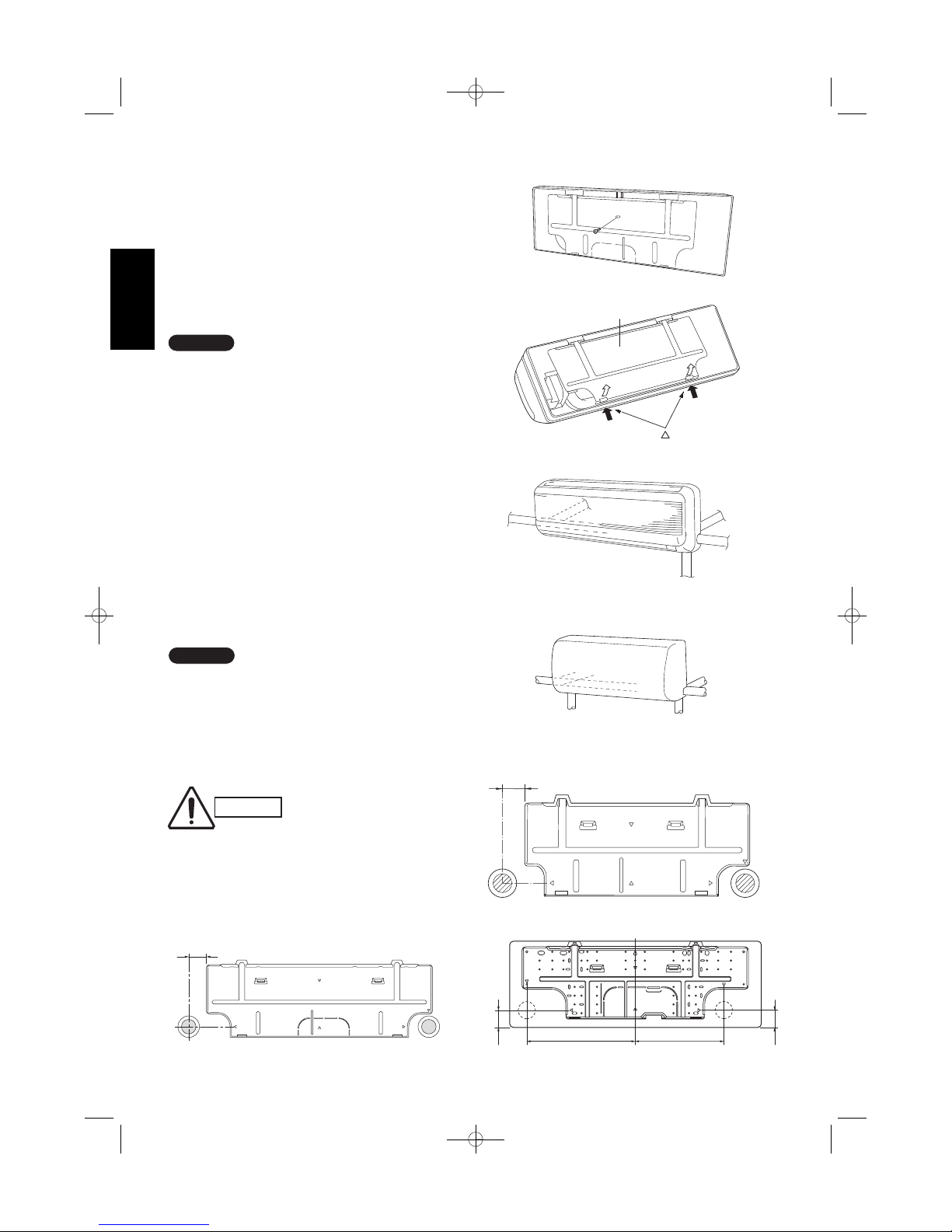
3. How to Install the Indoor Unit
3-1. Remove the Rear Panel from the Unit
(1) Remove and discard the set screw on the rear
panel except
SAP-KRV96EHDS, SAP-KMRV76EH,
SAP-KMRV96EH and SAP-KMRV126EH. (Fig. 6)
(2) Press the 2 LL marks on the frame cover and dis-
engage the stationary tabs from the frame. (Fig. 7)
(3) Remove the rear panel.
Tubing can be extended in 5 or 6 directions as shown
in Fig. 8a or 8b. Select the direction you need providing the shortest run to the outside unit.
G When left tubing is to be done, switch the drain
hose and drain cap. (For details, refer to “Switching
drain hose and drain cap” on page 17 and 18.)
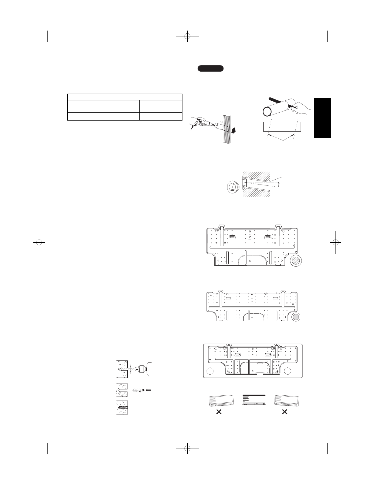
3-2. Make a Hole
(1) Place the rear panel from the indoor unit on the
wall at the location selected. Make sure the panel
is horizontal, using a carpenter’s level or tape measure to measure down from the ceiling. Wait until
after cutting the hole before attaching the rear
panel to the wall.
(2) Determine which side of the unit you should make
the hole for tubing and wiring. (Fig. 9a, 9b or 9c)
In the case of left-rear tubing, use the measurement
points from the edge of the rear panel for precise
placement of the hose outlet. (Fig. 9a, 9b or 9c)
(3) Before making the hole, check carefully that no
studs or pipes are directly run behind the spot to
be cut.
The above precautions are also applicable if tubing goes through the wall in any other location.
NOTE
NOTE
Fig. 9b
CAUTION
Also avoid areas where electrical wiring or conduits are
located.
70 mm
Fig. 9a
(SAP-KMRV74, KMRV94, KMRV124)
(SAP-KMRV76, KMRV96, KMRV126)
60 mm
(SAP-KMRV74, KMRV94, KMRV124) (SAP-KRV184, KRV244)
(SAP-KRV186, KRV246)
Fig. 9c
340 278
42
42
Left
tubing
Right
tubing
Right-rear
tubing
(recommended)
Right-downward
tubing
Left-rear
tubing
Left-downward
tubing
Fig. 8b
6
Fig. 8a
Fig. 7
(SAP-KRV184, KRV244) (SAP-KRV186, KRV246)
Fig. 6
(SAP-KMRV74, KMRV94, KMRV124)
(SAP-KMRV76, KMRV96, KMRV126) (SAP-KRV96)
(SAP-KRV184, KRV244)
(SAP-KRV186, KRV246)
(SAP-KRV96)
07-370 CMRV3146EH_IU ENG 2/6/08 1:31 PM Page 6
English
Hole should be made at a slight downward slant to the
outdoor side.
NOTE
Plastic cover
INSIDE OUTSIDE
Wall
Slight
angle
PVC pipe
(Locally purchased)
Fig. 12
PVC pipe (Locally purchased)
Cut at slight angle
Fig. 11
(4) Using a sabre saw, key hole saw or hole-cutting
drill attachment, cut a hole in the wall. See Table 4
and Fig. 10.
Table 4
(5) Measure the thickness of the wall from the inside
edge to the outside edge and cut PVC pipe at a
slight angle 6 mm shorter than the thickness of the
wall. (Fig. 11)
(6) Place the plastic cover over the end of the pipe (for
indoor side only) and insert the pipe in the wall.
(Fig. 12)
3-3. Install the Rear Panel on the Wall
Be sure to confirm that the wall is strong enough to
suspend the unit.
See either Item a) or b) below depending on the wall
type.
a) If Wooden Wall
(1) Attach the rear panel to the wall with the 8 screws
provided. (Fig. 13a, 13b or 13c)
If you are not able to line up the holes in the rear
panel with the beam locations marked on the wall,
use rawl plugs or toggle bolts to go through the
holes on the panel or drill 5 mm dia. holes in the
panel over the stud locations and then mount the
rear panel.
(2) Double check with a carpenter’s level or tape mea-
sure that the panel is level. This is important to
install the unit properly. (Fig. 14)
(3) Make sure the panel is flush against the wall. Any
space between the wall and unit will cause noise
and vibration.
b) If Block, Brick, Concrete or Similar Type Wall
Make 4.8 mm dia. holes in the wall. Insert rawl plugs
for appropriate mounting screws. (Fig. 15)
Hole Dia. (mm)
KMRV74 / KMRV94 / KMRV124 / KRV96 KRV184 / KRV244
KMRV76 / KMRV96 / KMRV126 KRV186 / KRV246
65 80
Fig. 13b
Fig. 14
4.8 mm dia. hole
Rawl plug
(Locally purchased)
Fig. 15
Fig. 13a
(SAP-KMRV74, KMRV94, KMRV124)
(SAP-KMRV76, KMRV96, KMRV126)
(SAP-KRV184, KRV244) (SAP-KRV186, KRV246)
Fig. 13c
Indoor
side
Outdoor
side
Fig. 10
(SAP-KRV96)
7
07-370 CMRV3146EH_IU ENG 2/6/08 1:31 PM Page 7
English
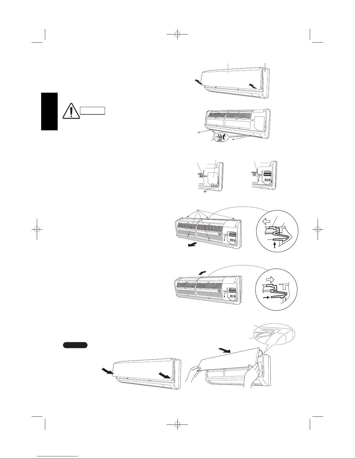
3-4. Removing and Installing the Grille
3-4-1. Indoor unit types
(SAP-KMRV74EH, KMRV94EH, KMRV124EH)
Basically, these models can be installed and wired without
removing the grille. If access to any internal part is needed,
follow the steps as given below.
How to remove the grille
(1) Grasp both ends of the air intake grille, and remove it
by opening towards the front and pulling towards you.
(Fig. 16a)
(2) Remove the 2 screws. (Fig. 16b)
(3) Remove the screw on the right side cover plate and
open the cover. (Fig. 17a)
(4) Take out the thermistor from the grille. (Fig. 17b)
(5) Pull the lower part of the grille towards you to remove.
(Fig. 18a)
(6) Use a standard screwdriver to push on the tabs to
remove the grille.
How to replace the grille
(1) Reinstall the grille into the lower part while aligning
its tabs on the upper part. (Fig. 18b) Insert the tabs
in the slots and push the lower part of the grille back
into position.
(2) Make sure that the grille and frame are firmly fitted
together by engaging the tabs.
(3) Attach the thermistor on the grille. (Fig. 17a)
(4) Close the cover and replace the screw. (Fig. 17a)
(5) Affix the grille with the 2 previously removed screws.
(Fig. 16b)
(6) Install the air intake grille.
(a) Allow the edge of the air intake grille to slide into
the top of the indoor unit, and then insert it all the
way inside. (Fig. 19a)
(b) Press the bottom right and left corners of the air
intake grille to attach it to the indoor unit. (Fig. 19b)
Attach so that the round pins at the top right and left
corners of the air
intake grille are
inserted into the
grooves at the top
right and left of the
indoor unit.
NOTE
Screw cover
Air intake grille
Grille
Fig. 16a
Fig. 16b
Cover
Thermistor
Fig. 17a
Thermistor
Fig. 17b
Fig. 18a
Grille
Frame
Ta b
Tab
*
*
Fig. 18b
*
*
Fig. 19b
Fig. 19a
Pin
Groove
CAUTION
Be sure to wear work gloves
during installation to avoid being
cut by the sharp aluminum fins
of the heat exchanger.
8
07-370 CMRV3146EH_IU ENG 2/6/08 1:31 PM Page 8
 Loading...