

Sanyo SAP-KRV91EH,SAP-CRV91EH Technical & Service Manual
TECHNICAL & SERVICE MANUAL
SAP-KRV91EH + SAP-CRV91EH
INVERTER SPLIT SYSTEM AIR CONDITIONER
SAP-CRV91EHSAP-KRV91EH
FILE NO.
REFERENCE NO. SM700386
W
Indoor Unit Outdoor Unit
IMPORTANT
These air conditioners employ new
refrigerant R410A.
Pay special attention when servicing
the unit.
➞ See “11. REFRIGERANT R410A
SPECIAL PRECAUTIONS WHEN
SERVICING THE UNIT”.
Indoor Model No. Product Code No. Outdoor Model No. Product Code No. Destination
SAP-KRV91EH 1 852 065 78 SAP-CRV91EH 1 852 065 79 Europe
i
IMPORTANT!
Please Read Before Starting
This air conditioning system meets strict safety and operating standards. As the installer or service person, it is an
important part of your job to install or service the system
so it operates safely and efficiently.
For safe installation and trouble-free operation, you
must:
●
Carefully read this instruction booklet before beginning.
●
Follow each installation or repair step exactly as
shown.
●
Observe all local, state, and national electrical codes.
●
Pay close attention to all warning and caution notices
given in this manual.
This symbol refers to a hazard or unsafe practice which
can result in severe personal
injury or death.
This symbol refers to a hazard
or unsafe practice which can
result in personal injury or
product or property damage.
If Necessary, Get Help
These instructions are all you need for most installation
sites and maintenance conditions. If you require help for
a special problem, contact our sales/service outlet or
your certified dealer for additional instructions.
In Case of Improper Installation
The manufacturer shall in no way be responsible for
improper installation or maintenance service, including
failure to follow the instructions in this document.
SPECIAL PRECAUTIONS
When Wiring
ELECTRICAL SHOCK CAN CAUSE
SEVERE PERSONAL INJURY OR DEATH.
ONLY A QUALIFIED, EXPERIENCED
ELECTRICIAN SHOULD ATTEMPT TO
WIRE THIS SYSTEM.
• Do not supply power to the unit until all wiring and tubing are completed or reconnected and checked.
• Highly dangerous electrical voltages are used in this
system. Carefully refer to the wiring diagram and
these instructions when wiring. Improper connections
and inadequate grounding can cause accidental
injury or death.
• Ground the unit following local electrical codes.
• Connect all wiring tightly. Loose wiring may cause
overheating at connection points and a possible fire
hazard.
When Transporting
Be careful when picking up and moving the indoor and
outdoor units. Get a partner to help, and bend your
knees when lifting to reduce strain on your back. Sharp
edges or thin aluminum fins on the air conditioner can
cut your fingers.
When Installing…
…In a Ceiling or Wall
Make sure the ceiling/wall is strong enough to hold the
unit’s weight. It may be necessary to construct a strong
wood or metal frame to provide added support.
…In a Room
Properly insulate any tubing run inside a room to prevent
“sweating” that can cause dripping and water damage to
walls and floors.
…In Moist or Uneven Locations
Use a raised concrete pad or concrete blocks to provide
a solid, level foundation for the outdoor unit. This prevents water damage and abnormal vibration.
…In an Area with High Winds
Securely anchor the outdoor unit down with bolts and a
metal frame. Provide a suitable air baffle.
…In a Snowy Area (for Heat Pump-type Systems)
Install the outdoor unit on a raised platform that is higher
than drifting snow. Provide snow vents.
When Connecting Refrigerant Tubing
• Use the flare method for connecting tubing.
• Apply refrigerant lubricant to the matching surfaces of
the flare and union tubes before connecting them,
then tighten the nut with a torque wrench for a leakfree connection.
• Check carefully for leaks before starting the test run.
When Servicing
• Turn the power OFF at the main power box (mains)
before opening the unit to check or repair electrical
parts and wiring.
• Keep your fingers and clothing away from any moving
parts.
• Clean up the site after you finish, remembering to
check that no metal scraps or bits of wiring have been
left inside the unit being serviced.
Others
• Ventilate any enclosed areas when installing or testing
the refrigeration system. Escaped refrigerant gas, on
contact with fire or heat, can produce dangerously
toxic gas.
• Confirm upon completing installation that no refrigerant gas is leaking. If escaped gas comes in contact
with a stove, gas water heater, electric room heater or
other heat source, it can produce dangerously toxic
gas.
WARNING
WARNING
CAUTION
CAUTION

ii
Table of Contents
Page
1. OPERATING RANGE................................................................................................................ 1
2. SPECIFICATIONS
2-1. Unit Specifications............................................................................................................ 2
2-2. Major Component Specifications...................................................................................... 3
2-3. Other Component Specifications...................................................................................... 5
3. DIMENSIONAL DATA................................................................................................................ 6
4. REFRIGERANT FLOW DIAGRAM
4-1. Refrigerant Flow Diagram................................................................................................. 8
5. PERFORMANCE DATA
5-1. Temperature Charts..........................................................................................................9
5-2. Air Throw Distance Charts................................................................................................ 10
5-3. Frequency Charts............................................................................................................. 11
6. ELECTRICAL DATA
6-1. Electrical Characteristics ..................................................................................................13
6-2. Electric Wiring Diagrams .................................................................................................. 14
7. INSTALLATION INSTRUCTIONS
7-1. Installation Site Selection .................................................................................................16
7-2. Refrigerant Tubing............................................................................................................ 19
7-3. Remote Control Unit Installation Position......................................................................... 20
8. MAINTENANCE
8-1. Changing Address of Indoor Unit and Remote Control Unit............................................. 21
8-2. Disconnecting and Connecting Positive Connector for Outdoor Unit............................... 21
9. FUNCTION
9-1. Functions for Operation.................................................................................................... 22
9-2. Protective Functions......................................................................................................... 25
10. TROUBLESHOOTING
10-1. Operating State................................................................................................................ 28
10-2. Troubleshooting Using the Self-Diagnostic Monitor......................................................... 29
10-3. Fault Assessment of Indoor/Outdoor Unit........................................................................ 31
10-4. Problems with Noise and Radio Interference................................................................... 32
11. REFRIGERANT R410A: SPECIAL PRECAUTIONS WHEN SERVICING UNIT
11-1. Characteristics of New Refrigerant R410A....................................................................... 33
11-2. Checklist Before Servicing ............................................................................................... 33
11-3. Tools Specifically for R410A............................................................................................. 35
11-4. Tubing Installation Procedures......................................................................................... 35
11-5. In Case of Compressor Malfunction................................................................................. 36
11-6. In Case Refrigerant is Leaking......................................................................................... 38
11-7. Charging Additional Refrigerant....................................................................................... 40

iii
11-8. Retro-Fitting Existing Systems......................................................................................... 40
12. CHECKING ELECTRICAL COMPONENTS
12-1. Measurement of Insulation Resistance............................................................................ 41
12-2. Checking Continuity of Fuse on PCB Ass’y ..................................................................... 42
12-3. Checking Motor Capacitor................................................................................................ 42
INSTRUCTION MANUAL
APPENDIX

1
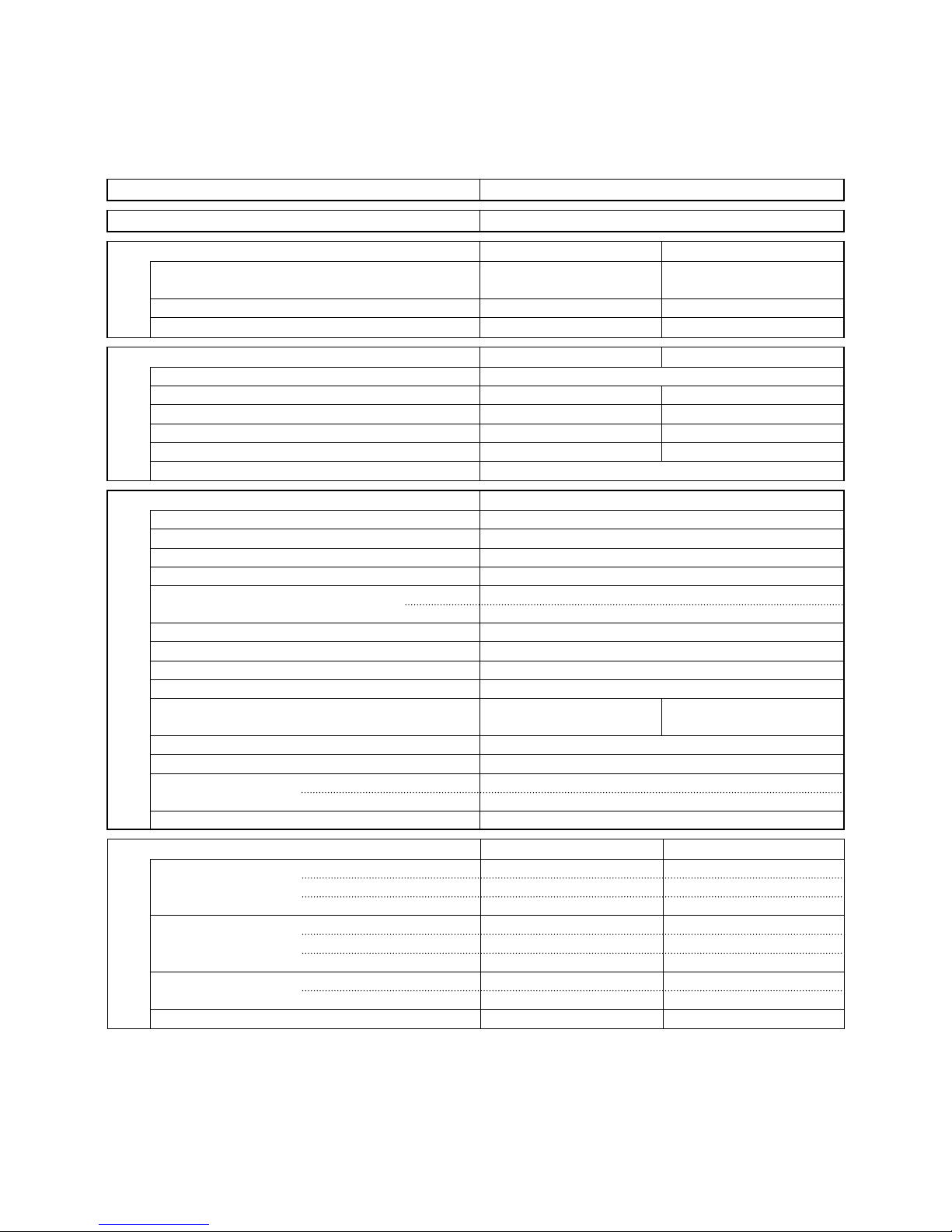
1. OPERATING RANGE
Temperature Indoor Air Intake Temp. Outdoor Air Intake Temp.
Cooling
Maximum 32°C D.B. / 23°C W.B. 43°C D.B.
Minimum 19°C D.B. / 14°C W.B. 19°C D.B.
Heating
Maximum 27°C D.B. 24°C D.B. / 18°C W.B.
Minimum 16°C D.B. –8°C D.B. / –9°C W.B.
2
DATA SUBJECT TO CHANGE WITHOUT NOTICE.
Remarks: Rating conditions are:
Cooling: Indoor air temperature 27°C D.B. / 19°C W.B.
Outdoor air temperature 35°C D.B. / 24°C W.B.
Heating: Indoor air temperature 20°C D.B.
Outdoor air temperature 7°C D.B. / 6°C W.B.
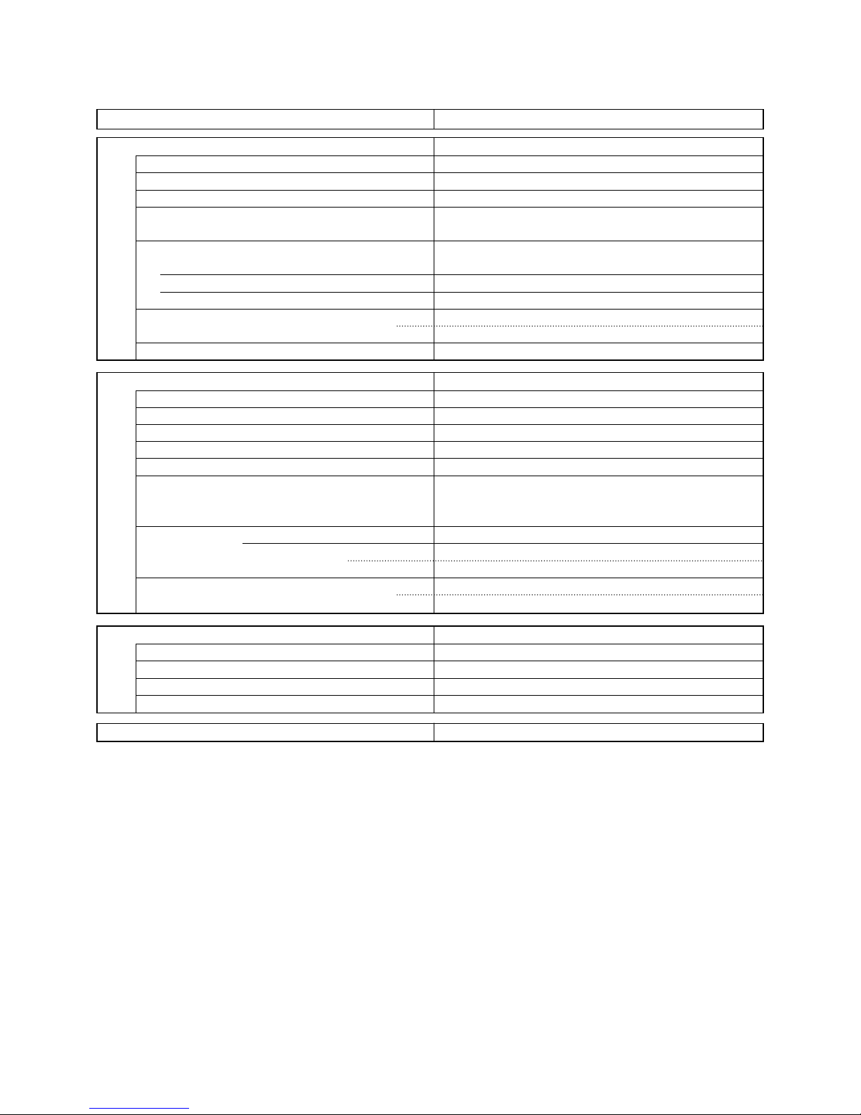
2. SPECIFICATIONS
2-1. Unit Specifications
Indoor unit SAP-KRV91EH
Outdoor unit SAP-CRV91EH
Power Source 220 – 230V Single phase 50Hz
Performance Cooling Heating
Capacity kW 2.80 (0.5 – 4.0) 4.20 (0.5 – 6.0)
BTU/h 9,600 (1,700 – 13,600) 14,330 (1,700 – 20,500)
Air circulation (High) m3/h 550 680
Moisture removal (High) Liters/h 1.1 —
Electrical Rating Cooling Heating
Available voltage range V 198 – 253
Running amperes A 3.6 (0.7 – 6.2) 4.6 (0.6 – 7.8)
Power input W 700 (105 – 1,360) 990 (90 – 1,760)
Power factor % 85 94
C.O.P. W/W 4.0 4.2
Compressor locked rotor amperes A 15
Features
Controls / Temperature control Microprocessor / I.C. thermostat
Control unit Wireless remote control unit
Timer ON / OFF 24 hours & Daily program, 1-hour OFF
Fan speeds Indoor / Outdoor 3 and Auto / Auto (Variable)
Airflow direction (Indoor) Horizontal Auto
Vertical Auto
Air filter Washable, Anti-Mold
Compressor Rotary (Hermetic)
Refrigerant / Amount charged at shipment g R410A / 1,290
Refrigerant control Electric Expansion Valve
Operation sound Indoor: Hi / Me / Lo dB-A 37 / 35 / 31 42 / 37 / 32
Outdoor: Hi dB-A 43 44
Refrigerant tubing connections Flare type
Max allowable tubing length at shipment m 7.5
Refrigerant Narrow tube mm (in.) 6.35 (1/4)
tube diameter Wide tube mm (in.) 9.52 (3/8)
Refrigerant tube kit / Accessories Optional / Air Clean Filter
Voltage Rating 230V
Dimensions & Weight Indoor Unit Outdoor Unit
Unit dimensions Height mm 285 620
Width mm 805 700
Depth mm 189 260
Package dimensions Height mm 264 681
Width mm 865 835
Depth mm 349 364
Weight Net kg 9.0 36.0
Shipping kg 12.0 38.0
Shipping volume m
3
0.08 0.207
3
2-2. Major Component Specifications
2-2-1. Indoor Unit
Indoor unit SAP-KRV91EH
DATA SUBJECT TO CHANGE WITHOUT NOTICE.
Control PCB
Part No. CB-KRV91EH
Controls Microprocessor
Control circuit fuse 250V 3.15A
Flap Motor and Louver Motor
Type Stepping motor
Model MP24S1-5V MP24S2-5V
Rating DC5V
Coil resistance (Ambient temp. 25°C) Ω WHT – BLU (respectively 4 wires): 70 ± 7%
Heat Exchanger Coil
Coil Aluminum plate fin / Copper tube
Rows 2
Fin pitch mm 1.3
Face area m
2
0.130
Fan & Fan Motor
Type Cross-flow
Q’ty … Dia. and length mm 1 … D88
Fan motor model … Q’ty DA4-23P36M … 1
No. of poles … rpm (230V, High) 4 … 1190
Nominal output W 10
Coil resistance (Ambient temp. 20°C) Ω BLU – RED: 5.67
RED – WHT: 5.67
WHT – BLU: 5.67
Safety devices Type —
Operating temp. Open °C —
Close —
Run capacitor µF —
VAC —
Remote Control Unit RCS-IHPS41E / RCS-IHCS4E
4
DATA SUBJECT TO CHANGE WITHOUT NOTICE.
2-2-2. Outdoor Unit
Outdoor unit SAP-CRV91EH
Control PCB POW-CV121CH
Compressor
Type Rotary (Hermetic)
Compressor model C-6RVN73HOT 80879680
Compressor oil … Amount cc FV68S … 350
Coil resistance (Ambient temp. 25°C) Ω C – R: 0.781
C – S: 0.781
Safety devices
CT (Peak current cut-off control) YES
Compressor discharge temp. control YES
Operation cut-off control in abnormal ambient temp. YES
Run capacitor µF —
VAC —
Crankcase heater —
Fan & Fan Motor
Type Propeller
Q’ty … Dia. mm 1 … ø400
Fan motor model … Q’ty DB8-33B280H … 1
No. of poles … rpm (230V, High) 8 … 730
Nominal output W 30
Coil resistance (Ambient temp. 20°C) Ω RED – WHT: 150.3
BLU – WHT: 150.3
BLU – RED: 150.3
Safety devices Type —
Operating temp. Open °C —
Close °C —
Run capacitor µF —
VAC —
Heat Exchanger Coil
Coil Aluminum plate fin / Copper tube
Rows 2
Fin pitch mm 1.4
Face area m
2
0.366
External Finish Acrylic baked-on enamel finish
5
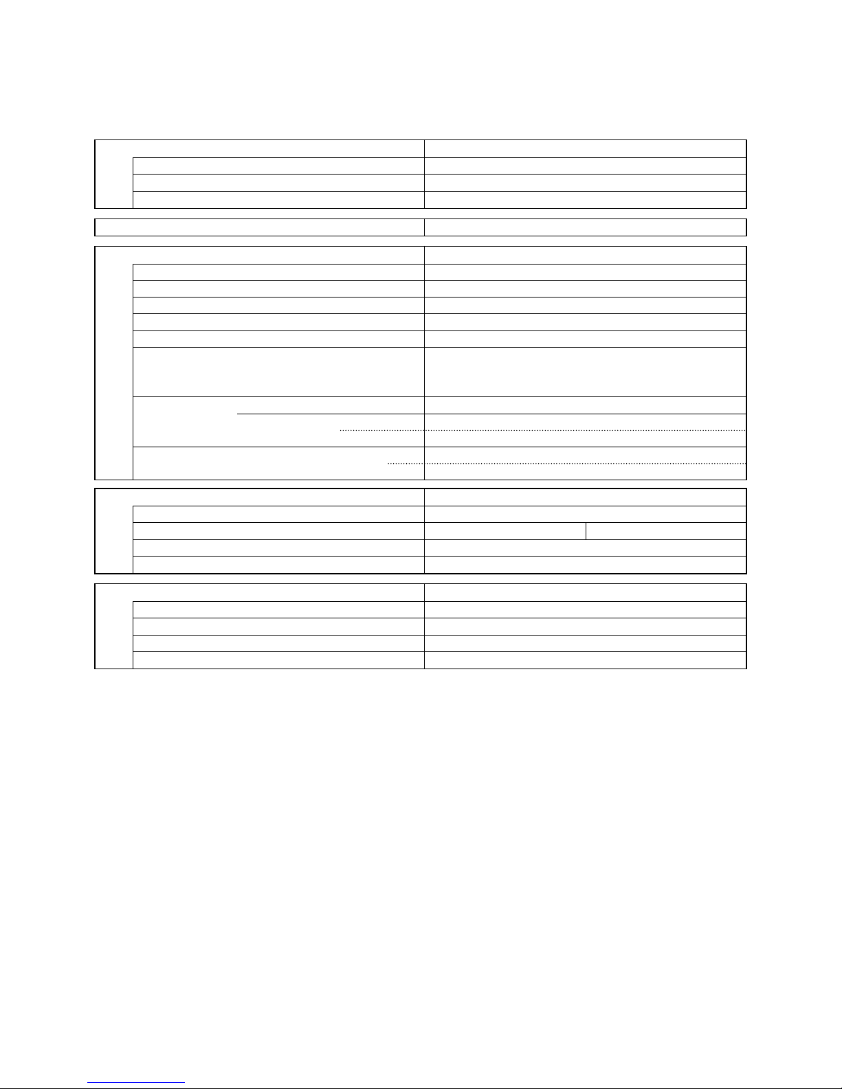
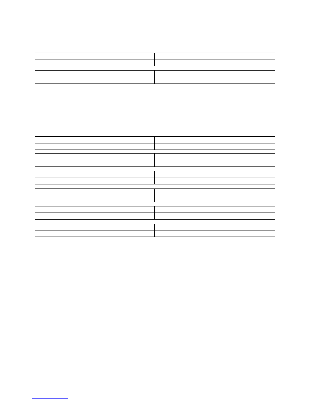
2-3. Other Component Specifications
2-3-1. Indoor Unit
Indoor unit SAP-KRV91EH
Thermistor (Room sensor) DTN-TKS150Y
Resistance kΩ 25°C 5.0 ± 3%
Thermistor (Coil sensor) DTN-TKS150Y
Resistance kΩ 25°C 58.3
DATA SUBJECT TO CHANGE WITHOUT NOTICE.
4-way Valve (SC) VPV-M0AJ503B (Coil), VHV-0202 (Valve)
Coil rating AC 220 /240V, 50Hz, 6W
Thermostat (Suction sensor) KTM-35D-S1
Resistance kΩ 0°C 15
Thermistor (Coil sensor) DTN-TKS163B
Resistance kΩ 0°C 15
Thermistor (Air sensor) KTEC-35D-S3
Resistance kΩ 0°C 15
Thermistor (Compressor sensor) DTN-TKS164B
Resistance kΩ 25°C 58.3
PTC Thermistor (TH) 912X24E400XR-A
Resistance Ω (at 25°C) 40
2-3-2. Outdoor Unit
Outdoor unit SAP-CRV91EH
DATA SUBJECT TO CHANGE WITHOUT NOTICE.
6
10 10785
805.0
285.0
126.0 40
193.0 (3)
10 56
61
182
23
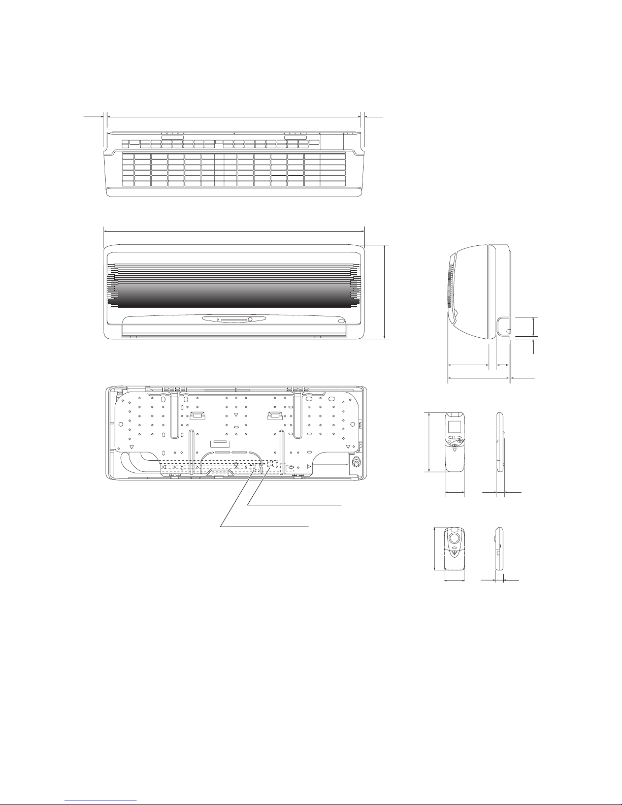
Remote control unit
People sensor
130
22
Wide tube ø9.52 (3/8")
Narrow tube ø6.35 (1/4")
3. DIMENSIONAL DATA
Indoor unit SAP-KRV91EH
Unit: mm

7
Outdoor unit SAP-CRV91EH
289700
538
538
234
300
300
234
151.5 46
180
81
620
16
70
Narrow tube service valve ø6.35 (1/4")
Wide tube service valve ø9.52 (3/8")
Location of Service Valves
Service valves are located behind the side panel.
See the illustration below.
NOTE
Unit: mm
8
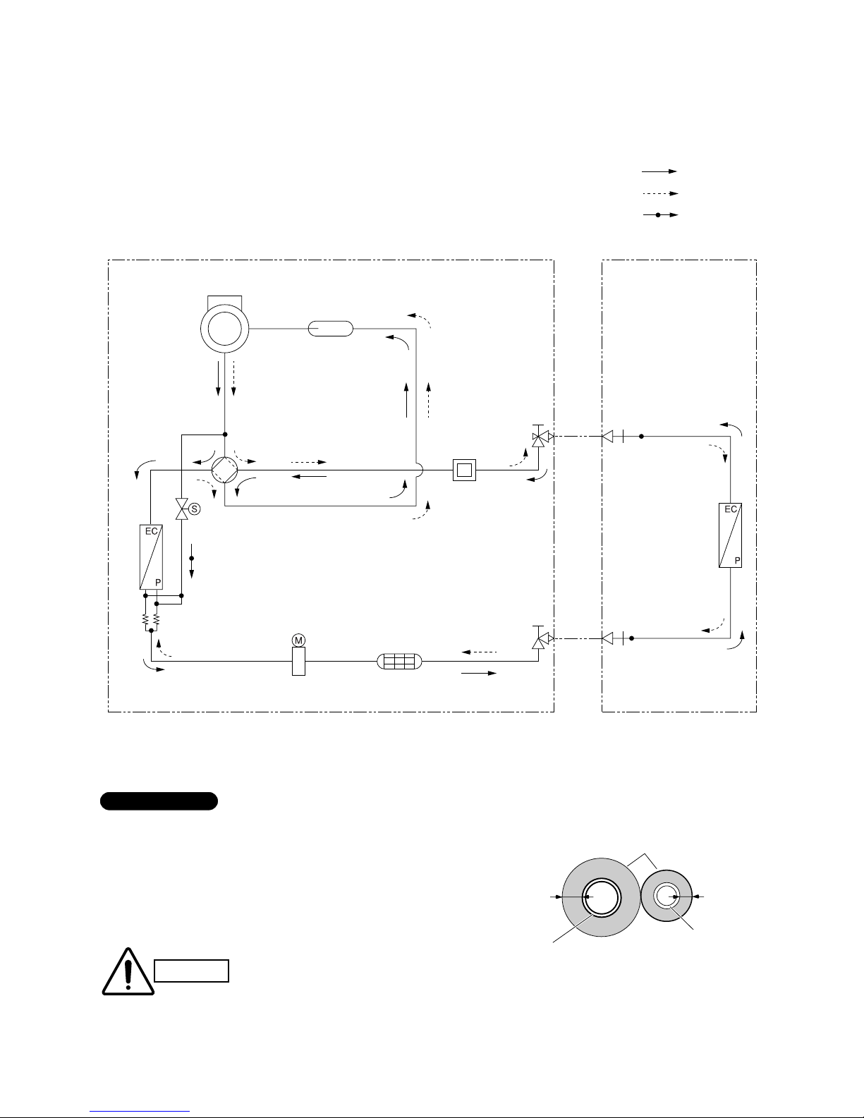
4. REFRIGERANT FLOW DIAGRAM
4-1. Refrigerant Flow Diagram
Indoor unit SAP-KRV91EH
Outdoor unit SAP-CRV91EH
ø9.52
ø6.35
Indoor heat
exchanger
Outdoor
heat exchanger
Outdoor unit Indoor unit
Wide tube
service valve
Narrow tube
service valve
Wide tube
nipple
Narrow tube
nipple
Accumulator
Muffler
Capillary
tube for distribution
EM valve
4-way valve
Cooling cycle
Heating cycle
Defrosting
Compressor
Strainer
Electronic expansion valve
Modulator
Insulation of Refrigerant Tubing
Because capillary tubing is used in the outdoor unit, both the
wide and narrow tubes of this air conditioner become cold. To
prevent heat loss and wet floors due to dripping of condensation, both tubes must be well insulated with a proper insulation material. The thickness of the insulation should be a
minimum 8 mm.
IMPORTANT
CAUTION
After a tube has been insulated,
never try to bend it into a narrow
curve because it can cause the
tube to break or crack.
Wide tube
Thickness:
Min. 8 mm
Insulation
Narrow tube
Thickness:
Min. 8 mm
9
5. PERFORMANCE DATA
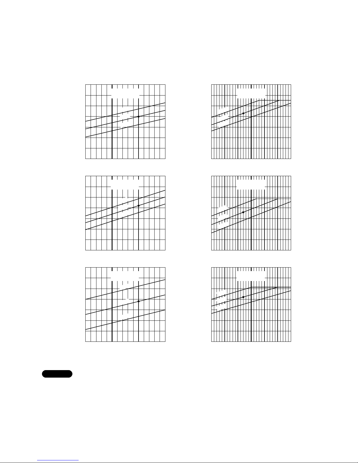
5-1. Temperature Charts
Indoor unit SAP-KRV91EH
Outdoor unit SAP-CRV91EH
■ Cooling Characteristics (50Hz, 230V) ■ Heating Characteristics (50Hz, 230V)
25 30 35 40
0.69
(6)
0.59
(5)
0.49
(4)
25 30 35 40
16
15
14
13
12
11
10
–5 0 5 10 15 20 25
2.45
(24)
2.06
(20)
1.67
(16)
1.28
(12)
–5 0 5 10 15 20 25
8
6
7
4
5
2
3
–5 0 5 10 15 20 25
60
55
50
45
40
35
30
25 30 35 40
Low pressure at wide tube service valve
MPa (kgf/cm
2
G)
High pressure at wide tube service valve
MPa (kgf/cm
2
G)
Outdoor inlet air D.B. temp.(˚C) Outdoor inlet air D.B. temp.(˚C)
Outdoor inlet air D.B. temp.(˚C) Outdoor inlet air D.B. temp.(˚C)
Outdoor inlet air D.B. temp.(˚C) Outdoor inlet air D.B. temp.(˚C)
Indoor inlet air
D.B. temp. (˚C)
Indoor inlet air
D.B. temp. (˚C)
20°C
24°C
27°C
30°C
Operating current (A)
Operating current (A)
Indoor inlet air
D.B. temp. (˚C)
Indoor inlet air
D.B. temp. (˚C)
24°C
27°C
30°C
Indoor discharge air temperature (˚C)
Indoor discharge air temperature (˚C)
Indoor inlet air
D.B. temp. (˚C)
Indoor inlet air
D.B. temp. (˚C)
24°C
27°C
30°C
23°C
17°C
20°C
17°C
23°C
5
4
3
2
20°C
17°C
23°C
Overload prevention operates to protect the air conditioner when outdoor ambient temperature becomes
extremely high in heating mode. (Refer to “9-2-3. Overload Prevention in Heating”.)
● … Points of rating condition
Black dots in above charts indicate the following rating conditions.
Cooling: Indoor air temperature 27°C D.B. / 19°C W.B. Heating: Indoor air temperature 20°C D.B.
Outdoor air temperature 35°C D.B. / 24°C W.B. Outdoor air temperature 7°C D.B. / 6°C W.B.
NOTE
10
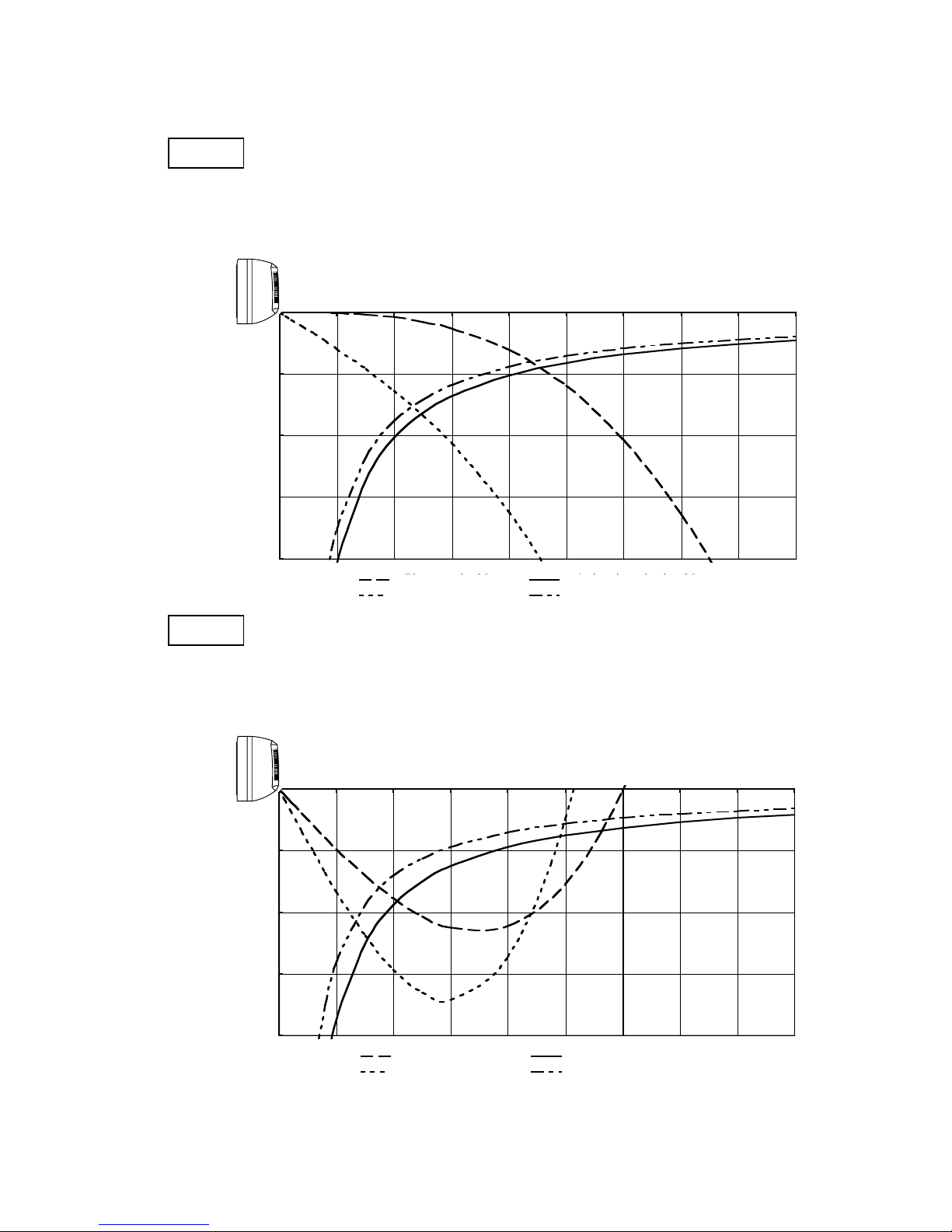
5-2. Air Throw Distance Charts
Indoor unit SAP-KRV91EH
Horizontal distance (m)
Axis air velocity (m/s)
Vertical distance (m)
Room air temp. : 20°C
Fan speed : High
Heating
Horizontal distance (m)
Axis air velocity (m/s)
Vertical distance (m)
Room air temp. : 27°C
Fan speed : High
Cooling
0
1
2
3
4
0123456789
: Flap angle 0° , : Axis air velocity 0°
: Flap angle 30° , : Axis air velocity 30
0
1
2
3
4
0123456789
: Flap angle 45° , : Axis air velocity 45
: Flap angle 60° , : Axis air velocity 60
Flap angle 0°
Flap angle 30°
Axis air velocity 0°
Axis air velocity 30°
Flap angle 45°
Flap angle 60°
Axis air velocity 45°
Axis air velocity 60°
11
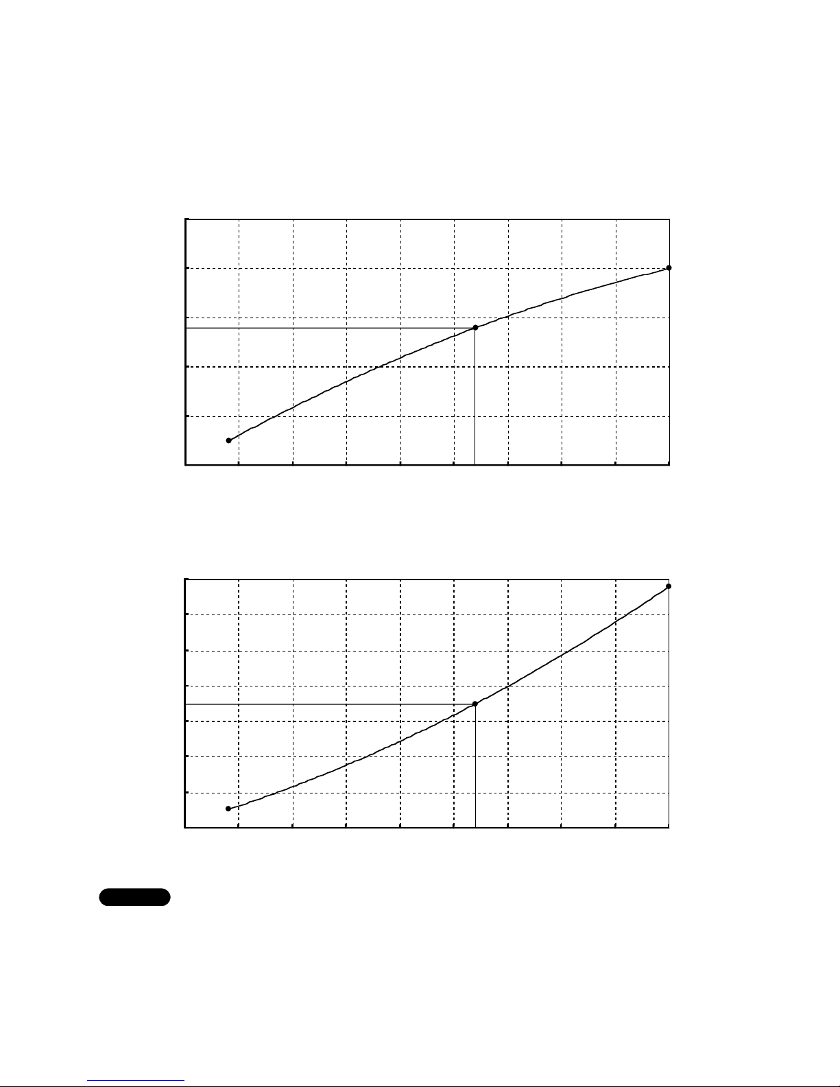
5-3. Frequency Charts
Indoor unit SAP-KRV91EH
Outdoor unit SAP-CRV91EH
1) Rating conditions in cooling mode are:
Indoor: 27°C D.B. / 19°C W.B.
Outdoor: 35°C D.B. / 24°C W.B.
2) Fan speed: High
NOTE
230V Single Phase 50Hz
0
200
400
600
800
1000
1200
1400
0102030405060708090
Operating Freqency (Hz)
Power Input (W)
54
700
■ Cooling
Power input (W)
Operating frequency (Hz)
0
1
2
3
4
5
0102030405060708090
Operating Freqency (Hz)
Cooling Capacity (kW)
54
2.8
Cooling capacity (kW)
Operating frequency (Hz)
12
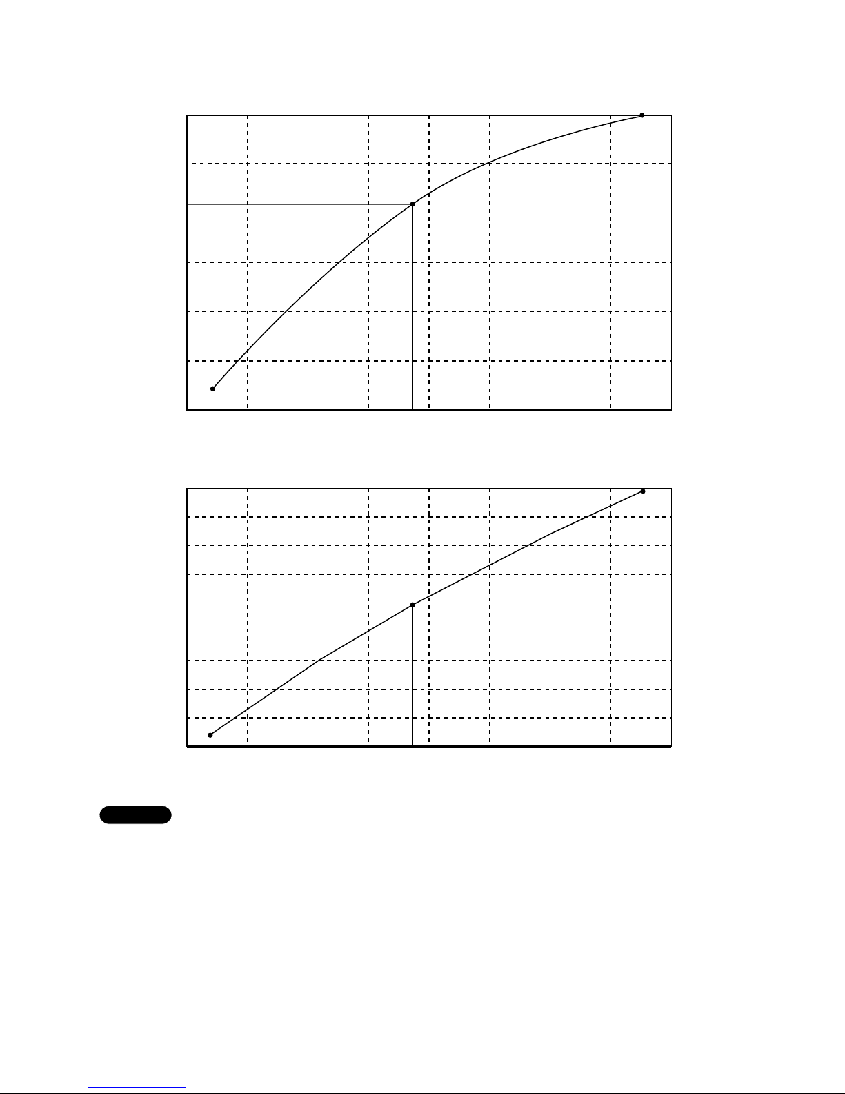
1) Rating conditions in heating mode are:
Indoor: 20°C D.B.
Outdoor: 7°C D.B. / 6°C W.B.
2) Fan speed: High
NOTE
6
5
4
3
2
1
0
020406076 80 100 120 140 160
4.2
Cooling capacity (kW)
Operating frequency (Hz)
230V Single Phase 50Hz
1800
1600
1200
1000
800
990
600
200
400
0
020406076 80 100 120 140 160
1400
Cooling capacity (kW)
Operating frequency (Hz)
■ Heating
13
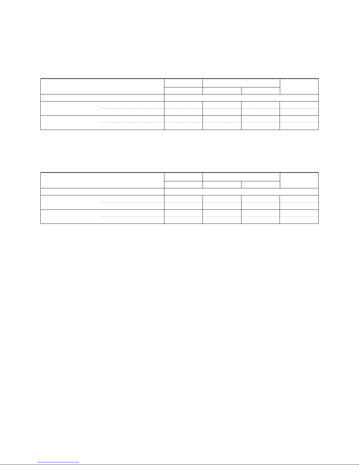
6. ELECTRICAL DATA
6-1. Electrical Characteristics
Indoor unit SAP-KRV91EH
Outdoor unit SAP-CRV91EH
Indoor Unit Outdoor Unit Complete Unit
Fan Motor Fan Motor Compressor
Performance at 230V Single phase 50Hz
Rating conditions Running amp. A 0.23 0.37 3.0 3.6
Power input kW 0.026 0.043 0.631 0.70
Full load Running amp. A 0.23 0.37 5.6 6.2
Power input kW 0.026 0.043 1.291 1.36
Rating conditions: Indoor air temperature 27°C D.B. / 19°C W.B.
Outdoor air temperature 35°C D.B.
Rating conditions: Indoor air temperature 20°C D.B.
Outdoor air temperature 7°C D.B. / 6°C W.B.
Indoor Unit Outdoor Unit Complete Unit
Fan Motor Fan Motor Compressor
Performance at 230V Single phase 50Hz
Rating conditions Running amp. A 0.35 0.34 3.91 4.6
Power input kW 0.041 0.037 0.912 0.99
Full load Running amp. A 0.35 0.34 7.11 7.8
Power input kW 0.041 0.037 1.682 1.76
Heating
Cooling
14
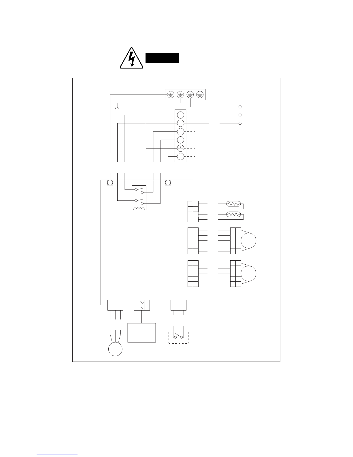
6-2. Electric Wiring Diagrams
Indoor unit SAP-KRV91EH
WARNING
To avoid electrical shock hazard, be sure to
disconnect power before checking, servicing
and/or cleaning any electrical parts.
8512-5253-520xx-2
1
3
5
2
4
6
Earth plate
Power cord
Terminal
plate
Power relay
4P
Room/coil
5P
Flap
(White)
5P
Louver
(Red)
Flap motor
Thermistor (coil)
Thermistor (room)
Louver motor
CONTROLLER
FM
Evaporator
To outdoor unit
L
N
1
2
4
GRN/YELGRN/YEL
BRN
BLU
GRN/YEL
1
2
3
4
5
4
3
2
1
1
321
321
101
101
321
321
2
3
4
5
1
2
3
4
5
4
3
2
1
1
2
3
4
5
1
2
3
4
5
1
2
3
4
5
1
2
3
4
5
1
2
3
4
5
BLK
BLK
ORG
ORG
WHT
GRY
GRY
GRY
GRY
WHT
GRY
GRY
GRY
GRY
WW
GRN/YEL
BRN
BLU
RED
WHT
BLK
3P
Power-SW
Power SW
10P
Lamp
3P
DCM
Fan
motor
IND lamp
assy
WHT
BLU
RED
WHT
WHT
Louver
Flap
15
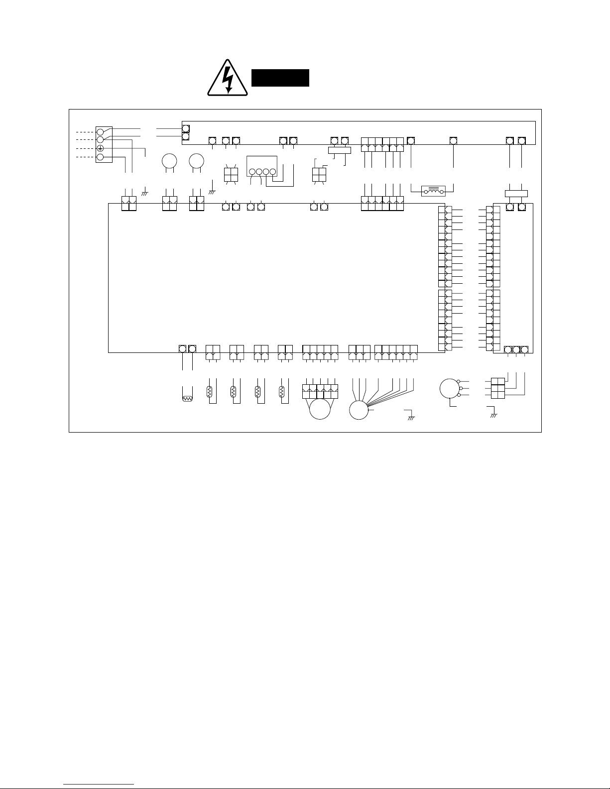
Outdoor unit SAP-CRV91EH
WARNING
To avoid electrical shock hazard, be sure to
disconnect power before checking, servicing
and/or cleaning any electrical parts.
1
2
4
Terminal
plate
From indoor unit
W
W
W W
W W
+ +
W WW
IN1
E
OUT1
OUT2
DCIN+
DCIN–
DCOUT+
DCOUT–
IN2
BLK
WHT
RED
WHT
GRN/YEL
1 3
13
1 2123344556
11
22
33
44
55
66
77
88
99
10 10
11 11
12 12
6
12 12
11 11
10 10
99
88
77
66
55
44
33
22
11
1 2123344556
6
(BLK)
SI
1 3
13
(WHT)
SV
GRN/YEL
21
21
YEL
ORG
YEL
ORG
W
W W
W W
21
21
RED
BLK
RED
BLK
ACIN2
ACIN1
ACOUT2
(BLK)
A – B
HIC2
(RED)
HIC1
(RED)
(WHT)
A – B
Reactance
L1
W W
L2 DC 0V
–+
DC+DC–
ACOUT1
Ferrite
core
Diode
AC AC
–+
WHT
WHT
BLU
YEL
WHT
WHT
WHT
WHT
WHT
VLT
ORG
CONTROLLER B
+
+
W
DC 280V
+
BLK
WHT
WHT
WHT
WHT
WHT
WHT
WHT
11
22
33
44
55
66
77
88
99
9
22
8
21
7
20
619
518
417
316
215
114
BLK
WHT
WHT
WHT
WHT
WHT
WHT
WHT
WHT
WHT
WHT
HIC
U
+V+
W
11
22
33
CM
RED
RED
WHT
WHT
BLU
BLU
RED
BLU
Compressor
motor
R
S
T
GRN/YEL
GRN/YEL
CONTROLLER A
12123
3
13135
5
44556
6
(WHT)
SENSE
(WHT)
FM
(WHT)
MV-1
Fan motor
Magnetic
coil
FM
MV
WHT
PNK
BLK
BRN
YEL
VLT
121233445
5
ORG
RED
YEL
GRY
BLK
6 56522114
4
Solenoid valve
BLU
BLU
SV
1 3
13
(RED)
RV
4-way valve
BLU
BLU
RV
PTC
(YEL)
OUT
DOOR
Ooutdoor
thermistor
12
12
BLK
BLK
(WHT)
COMP
Compressor
thermistor
12
12
BLK
BLK
(BLK)
COIL
Coil thermistor
12
12
YEL
YEL
YEL
YEL
(RED)
SUC
SUC thermistor
12
12
W
PTC2
W
PTC1
YEL
YEL
BLK
RED
Ferrite
core
8512-5253-521xx-2
16
7. INSTALLATION INSTRUCTIONS
7-1. Installation Site Selection
7-1-1. Indoor Unit
AVOID:
●
direct sunlight.
●
nearby heat sources that may affect performance of
the unit.
●
areas where leakage of flammable gas may be
expected.
●
places where large amounts of oil mist exist.
DO:
●
select an appropriate position from which every corner of the room can be uniformly cooled. (High on a
wall is best.)
●
select a location that will hold the weight of the unit.
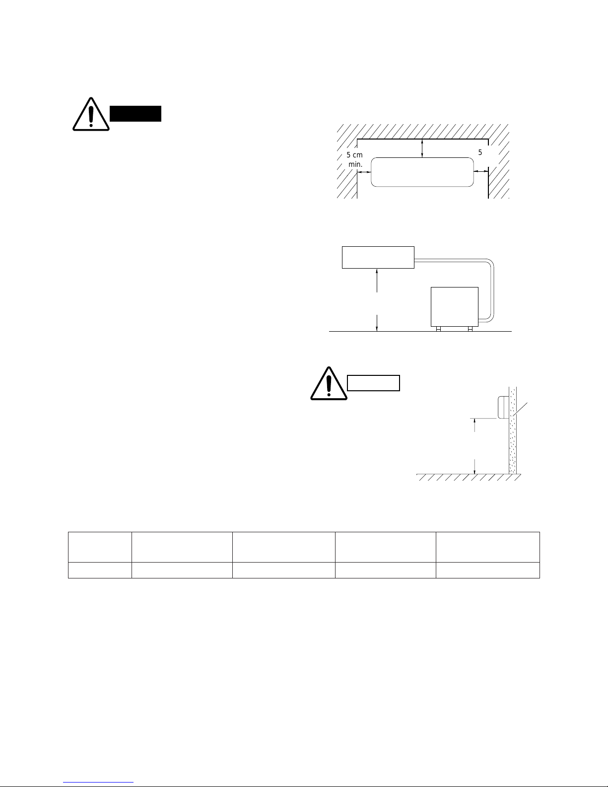
●
select a location where tubing and drain hose have
the shortest run to the outside. (Fig. 1)
●
allow room for operation and maintenance as well as
unrestricted air flow around the unit. (Fig. 2)
●
install the unit within the maximum elevation difference (H) above or below the outdoor unit and within
a total tubing length (L) from the outdoor unit as
detailed in Table 1 and Fig. 3.
Table 1
5 cm
min.
5 cm
min.
5 cm min.
Front View
Fig. 1
INDOOR
UNIT
Tubing length (L)
OUTDOOR
UNIT
Elevation
difference (H)
Fig. 2
WARNING
To prevent abnormal heat
generation and the possibility
of fire, do not place obstacles,
enclosures and grilles in front
of or surrounding the air conditioner in a way that may
block air flow.
Indoor unit
Floor level
Wall
Minimum height
from floor level
1.5 m
Fig. 3
For stable operation of
the air conditioner, do not
install wall-mounted type
indoor units under 1.5 m
from floor level.
CAUTION
Max. Allowable Tubing Limit of Tubing Limit of Elevation Required Amount of
Model Length at Shipment Length (L) Difference (H) Additional Refrigerant
(m) (m) (m) (g/m)
*
KRV91 7.5 15 7 15
*
If total tubing length becomes 7.5 to 15 m (max.), charge additional refrigerant (R410A) by 15 g/m.
No additional compressor oil is necessary.
17
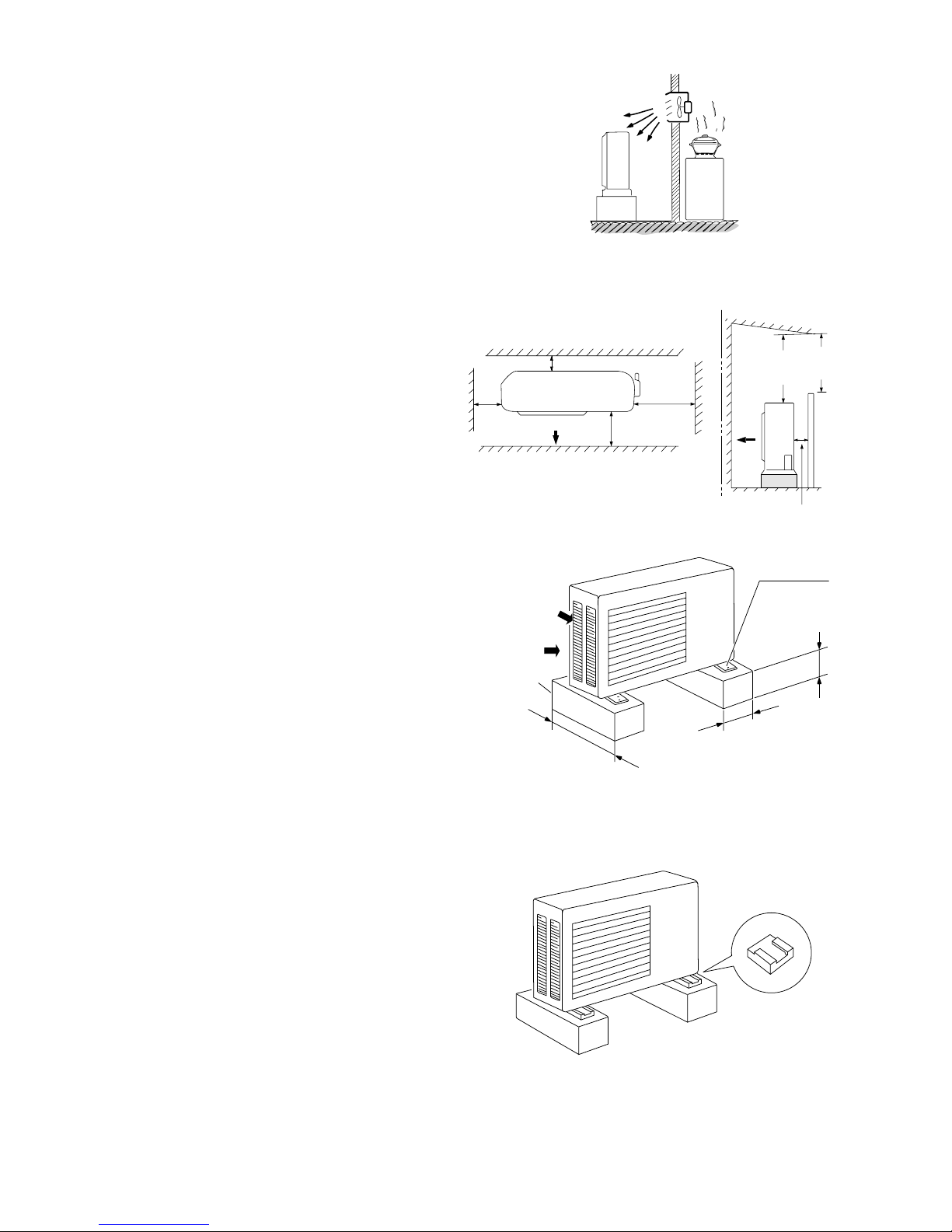
7-1-2. Outdoor Unit
AVOID:
●
heat sources, exhaust fans, etc. (Fig. 4)
●
damp, humid or uneven locations.
DO:
●
choose a place as cool as possible.
●
choose a place that is well ventilated.
●
allow enough room around the unit for air intake/
exhaust and possible maintenance. (Fig. 5a)
●
provide a solid base (level concrete pad, concrete
block, 10 ×40 cm beams or equal), a minimum of
10 cm above ground level to reduce humidity and
protect the unit against possible water damage
and decreased service life. (Fig. 5a)
●
Install cushion rubber under unit’s feet to reduce
vibration and noise. (Fig. 5b)
●
use lug bolts or equal to bolt down unit, reducing
vibration and noise.
Outdoor unit
Hot air
Heat source
Exhaust fan
NO
Fig. 4
Air intake
Concrete
or equal
About 10 cm
Min. 10 cm
Anchor bolts
(4 pcs.)
About 40 cm
Fig. 5a
Cushion rubber
Fig. 5b
Air intake Min. 10 cm
Air discharge
Min.
5 cm
Min.
40 cm
Valve
side
Min.
25 cm
Min.
2 m
Min.
2 m
Min. 10 cm
Air intake
Ground
Obstacle
Obstacle above
Air discharge
18
7-1-3. Recommended Wire Length and Diameter
Regulations on wiring diameter differ from locality to locality. For field wiring requirements, please refer to your
local electrical codes. Carefully observe these regulations when carrying out the installation.
Table 2 lists recommended wire lengths and diameters for power supply systems.
Refer to the wiring system diagram (Fig. 6) for the meaning of “A” and “B” in Table 2.
Table 2
NOTE
Cross-Sectional (A)+(B) (A) Power Supply Wiring Length (m)
Fuse or Circuit
Area (mm2) (B) Power Line Length (m)
Model 2 3.5
Capacity
CRV91 33 51 10A
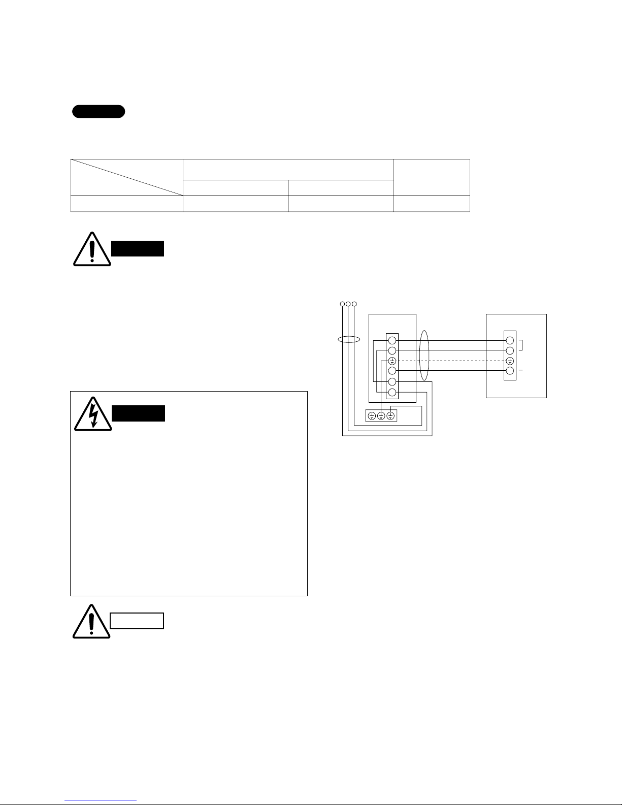
INDOOR UNIT OUTDOOR UNIT
TerminalTerminal
Power
line
Control
line
Ground line
Power supply:
1ø 50 Hz,
220 V – 230 VAC
1
4
2
1
4
2
L
N
(B)
(A)
Fig. 6
CAUTION
Be sure to connect the power
supply line to the indoor unit
as shown in the wiring diagram. The outdoor unit draws
its power from the indoor unit.
WIRING SYSTEM DIAGRAM
WARNING
●
Be sure to comply with local
codes on running the wire
from the indoor unit to the
outdoor unit (size of wire
and wiring method, etc.).
●
Each wire must be firmly
connected.
●
No wire should be allowed
to touch refrigerant tubing,
the compressor, or any
moving part.
●
To avoid the risk of electrical shock, each air
conditioner unit must be grounded.
●
For the installation of a grounding device,
please observe local electrical codes.
●
Grounding is necessary, especially for units
using inverter circuits, in order to release
charged electricity and electrical noise caused
by high tension. Otherwise, electrical shock
may occur.
●
Place a dedicated ground more than 2 meters
away from other grounds and do not have it
shared with other electric appliances.
WARNING

19
Deburring
Before
After
Fig. 7
Reamer
Copper
tubing
Fig. 8
Flare tool
Flare nut
Copper
tubing
Fig. 9
Apply refrigerant
lubricant here and here
0 to
0.5 mm
Fig. 11
Fig. 10
7-2. Refrigerant Tubing
7-2-1. Use of the Flaring Method
Many of the conventional split system air conditioners
employ the flaring method to connect refrigerant tubes
which run between indoor and outdoor units. In this
method, the copper tubes are flared at each end and
connected with flare nuts.
7-2-3. Flaring Procedure with a Flare Tool
a) Cut the copper tube to the required length with a
tube cutter. It is recommended to cut approx. 30 –
50 cm longer than the tubing length you estimate.
b) Remove burrs at the end of the copper tube with a
tube reamer or file. This process is important and
should be done carefully to make a good flare.
(Fig. 7)
When reaming, hold the tube end downward and be
sure that no copper scraps fall into the tube. (Fig. 8)
c) Remove the flare nut from the unit and be sure to
mount it on the copper tube.
d) Make a flare at the end of copper tube with a flare
tool.*(Fig. 9)
(*Use “RIGID” or equivalent.)
e) Use the special flare tool for R410A for making a
flare. If the conventional flare tool for R22 is utilized, use the spacer provided. (Fig. 10)
A good flare should have the following characteristics:
●
inside surface is glossy and smooth.
●
edge is smooth.
●
tapered sides are of uniform length.
7-2-4. Caution before Connecting Tubes
Tightly
a) Be sure to apply a sealing cap or water-proof tape
to prevent dust or water from getting into the tubes
before they are used.
b) Be sure to apply refrigerant lubricant to the match-
ing surfaces of the flare and union before connecting them together. This is effective for reducing gas
leaks. (Fig. 11)
c) For proper connection, align the union tube and
flare tube straight with each other, then screw on
the flare nut lightly at first to obtain a smooth
match. (Fig. 12)
NOTE
NOTE
Where the R410A
flare tool is used
1.2 mm
Spacer
Where the conventional flare tool
is utilized (clutching method)
Flare nut
Union
Fig. 12
By using the spacer, the pipe must be adjusted so that 1.2 mm of the pipe protrudes.
20
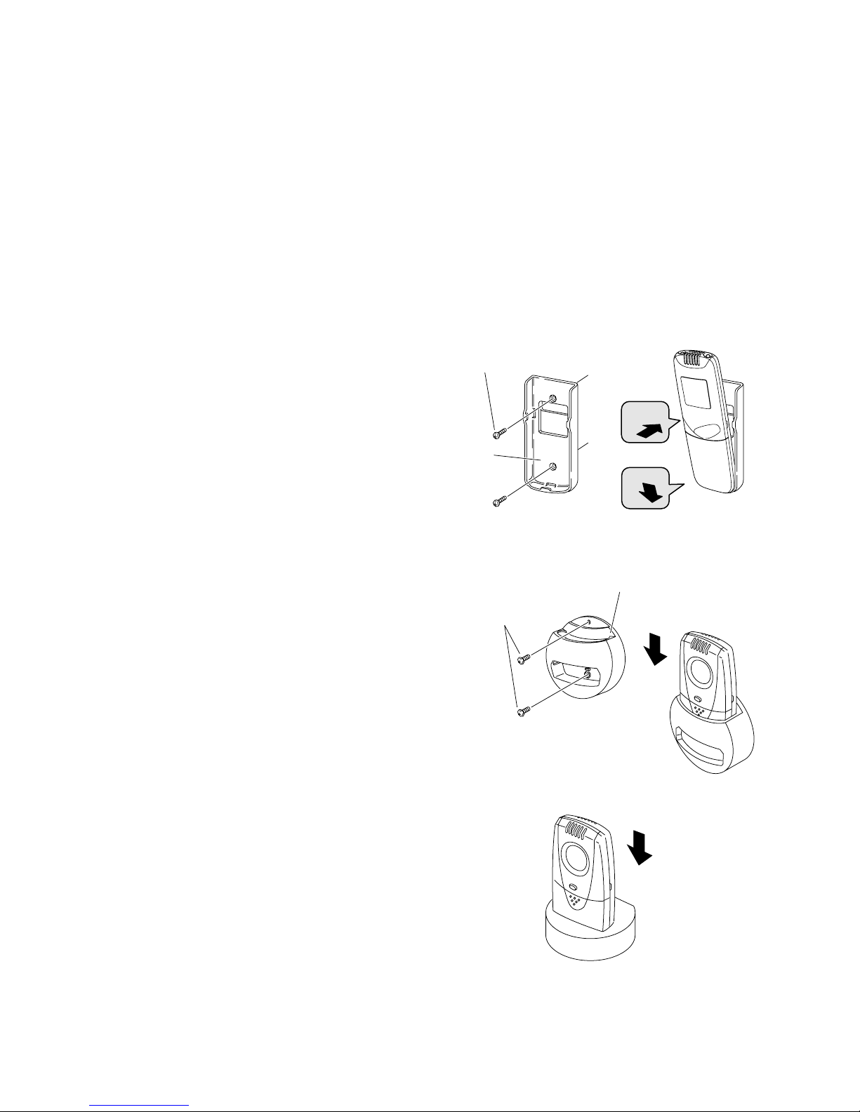
7-3-1. Mounting on a Wall
a) Remote Control Unit
When attaching to wall
(1) Confirm the indoor unit beeps when the ON/OFF
button is pressed at the wall location where the
remote control unit is to be attached, then attach
the holder to the wall. (Fig. 13)
(2) When taking out the remote control unit, pull it
from the holder. (Fig. 14)
When using the remote control unit
●
Point the transmission portion of the remote control
unit at the receiver area of the indoor unit when
operating the remote control unit, and during operation of the air conditioner.
●
Do not place objects which may block the transmitted signals between the receiver and the remote
control unit.
b) People Sensor
How to use the remote control unit holder
Turn the power source switch ON at the spot where
you intend to install the holder, and confirm the
indoor unit beeps. (Figs. 14 and 15)
Truss-head tapping screws
4 × 16 mm (supplied)
Holder for People Sensor-type
remote control unit
Insert
Fig. 14
When attaching to wall
Insert
Fig. 15
When placed on table, etc.
7-3. Remote Control Unit Installation Position
The remote control unit can be operated from either a non-fixed position or a wall-mounted position.
To ensure that the air conditioner operates correctly, do not install the remote control unit in the following places:
●
In direct sunlight
●
Behind a curtain or other place where it is covered
●
More than 8 m away from the air conditioner
●
In the path of the air conditioner’s airstream
●
Where it may become extremely hot or cold
●
Where it may be subject to electrical or magnetic interference
●
Where the temperature changes rapidly (near heater, etc.)
●
Where strong vibration or shock occurs
●
Where there are obstacles which may block or interfere with the infrared signal, such as glass
●
Near telephone, computer or radio
●
Outside the detectable range, such as on top of
refrigerator
1
2
Truss-head
tapping screws
4 × 16 mm (supplied)
Remote
control
unit holder
Press
Hook
Fig. 13
21
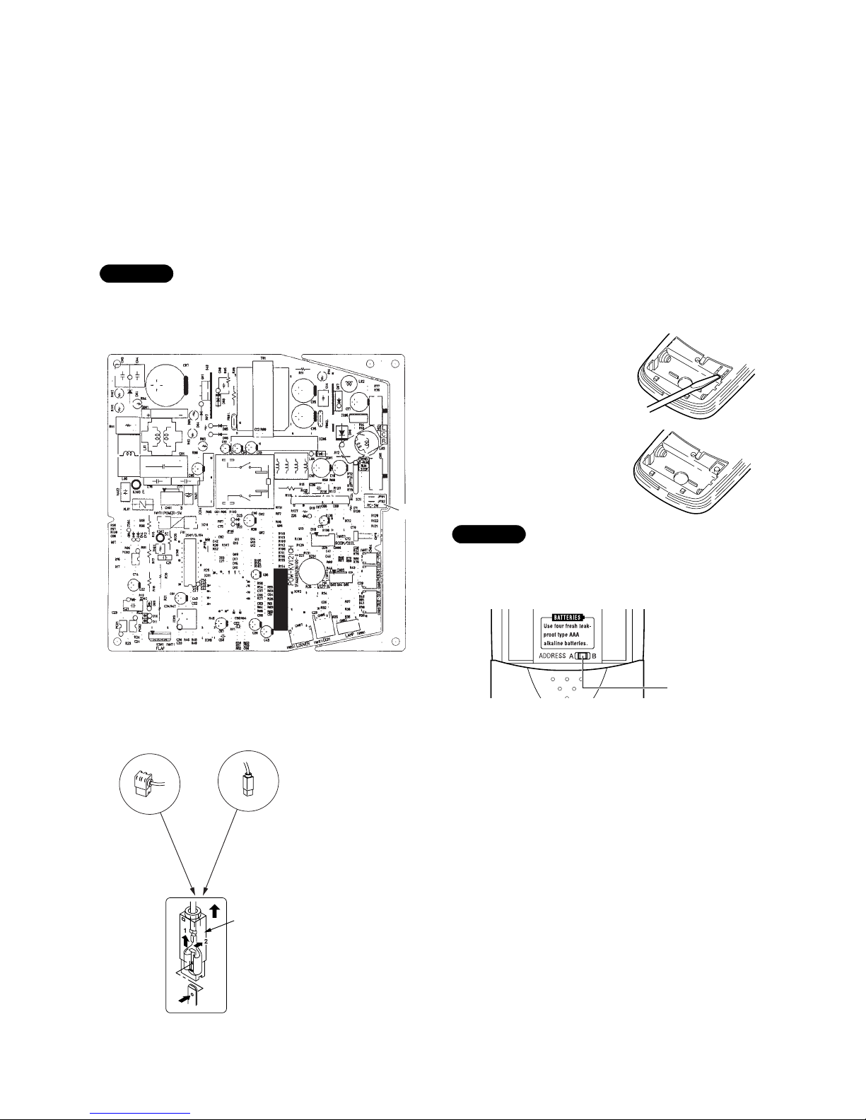
8. MAINTENANCE
8-1. Changing Address of Indoor Unit and Remote Control Unit
If the operation is disturbed by radio interference of the remote control signals, change the address of the remote
control unit by cutting the jumper wire on the PCB A of the indoor unit.
To Change Address on PCB
(1) Cut jumper wire (JP02) on the indoor unit PCB.
(2) Switch the address switch on the remote control unit to “B” position.
(3) After inserting the batteries, press reset (
リセット
) button.
Once changed, you cannot restore the original address setting of the remote control unit.
NOTE
Pull the cover upward
When the cover is pulled upward, the lock is
released with the sequence of 1 and 2.
Address switch
Control PCB (POW-KV121CH) on Indoor Unit
JP02
(1) Remove tab for changing
the address (
アドレス
) of
the remote control unit.
(2) When it is removed, the
address (
アドレス
) is set
to B.
To Change Address on Remote Control
People Sensor-type remote control unit
(RCS-IHCS4E)
8-2. Disconnecting and Connecting Positive Connector for Outdoor Unit
One of the two types of connectors illustrated at left is used. Their
basic structure is the same for each.
How to Disconnect
Hold the resin connector cover, and pull the connector off.
You cannot disconnect the connector by pulling the wire since
it is locked inside. Always hold the cover to disconnect. (See
illustration at left.) For the connector without the resin cover,
push the lock in the direction of “2” while pulling it off.
How to Connect
In order to connect, hold the resin cover of the connector and
push it in. Confirm the click sound for the inside lock.
Remove the batteries before switching
the address switch.
NOTE
 Loading...