

Sanyo SAP-KCRV243GJH,SAP-KCRV243GJ,SAP-KCRV303GJH,SAP-KCRV303GJ Technical & Service Manual
TECHNICAL & SER VICE MANUAL
SAP-KCRV243GJH
SAP-KCRV243GJ
SAP-KCRV303GJH
SAP-KCRV303GJ
DC INVERTER SPLIT AIR CONDITIONER
Wall Mounted Type Indoor Unit
IMPORTANT
These air conditioners employ
new refrigerant R410A.
Pay special attention when
servicing the unit.
SAP-KRV243GJH
SAP-KRV243GJ
SAP-KRV303GJH
SAP-KRV303GJ
Power Source:240V 50Hz
Outdoor unit
SAP-CRV243GJH
SAP-CRV243GJ
SAP-CRV303GJH
SAP-CRV303GJ
i
For safe installation and trouble-free operation, you
must:
Carefully read this instruction booklet before
beginning.
Follow each installation or repair step exactly as
shown.
Observe all local, state, and national electrical codes.
Pay close attention to all warning and caution notices
given in this manual.
Important!
Please Read Before Starting
This air conditioning system meets strict safety and
operating standards. As the installer or service person,
it is an important part of your job to install or service the
system so it operates safely and efficiently.
This symbol refers to a hazard or
unsafe practice which can result
in severe personal injury or
death.
This symbol refers to a hazard or
unsafe practice which can result
in personal injury or product or
property damage.
WARNING
CAUTION
If Necessary, Get Help
These instructions are all you need for most installation
sites and maintenance conditions. If you require help
for a special problem, contact our sales / service outlet
or your certified dealer for additional instructions.
In Case of Improper Installation
The manufacturer shall in no way be responsible for
improper installation or maintenance service, including
failure to follow the instructions in this document.
Special Precautions
• Do not supply power to the unit until all wiring and
tubing are completed or reconnected and checked.
Highly dangerous electrical voltages are used in this
system. Carefully refer to the wiring diagram and
these instructions when wiring. Improper connections
and inadequate grounding can cause accidental
injury or death.
Ground the unit following local electrical codes.
Connect all wiring tightly. Loose wiring may cause
overheating at connection points and a possible fire
hazard.
•
•
•
When Wiring
ELECTRICAL SHOCK CAN CAUSE
SEVERE PERSONAL INJURY OR
DEATH. ONLY A QUALIFIED,
EXPERIENCED ELECTRICIAN SHOULD
ATTEMPT TO WIRE THIS SYSTEM.
WARNING
When Transporting
Be careful when picking up and moving the indoor and
outdoor units. Get a partner to help, and bend your
knees when lifting to reduce strain on your back.Sharp
edges or thin aluminum fins on the air conditioner can
cut your fingers.
When Connecting Refrigerant Tubing
• Use the flare method for connecting tubing.
• Apply refrigerant lubricant to the matching surfaces
of the flare and union tubes before connecting them,
then tighten the nut with a torque wrench for a leakfree connection.
• Check carefully for leaks before starting the test run.
When Servicing
•
Turn the power off at the main power box (mains)
before opening the unit to check or repair electrical
parts and wiring.
• Keep your fingers and clothing away from any
moving parts.
• Clean up the site after you finish, remembering to
check that no metal scraps or bits of wiring have
been left inside the unit being serviced.
CAUTION
• Confirm upon completing installation that no
refrigerant gas is leaking. If escaped gas comes in
contact with a stove, gas water heater, electric room
heater or other heat source, it can produce
dangerously toxic gas.
• Do not install only a single indoor unit.
•
Ventilate any enclosed areas when installing or
testing the refrigeration system. Escaped refrigerant
gas, on contact with fire or heat, can produce
dangerously toxic gas.
Others
When Installing…
…In a Ceiling or Wall
Make sure the ceiling / wall is strong enough to hold the
unit’s weight. It may be necessary to construct a strong
wood or metal frame to provide added support.
…In a Room
Properly insulate any tubing run inside a room to
prevent “sweating” that can cause dripping and water
damage to walls and floors.
…In Moist or Uneven Locations
Use a raised concrete pad or concrete blocks to
provide a solid, level foundation for the outdoor unit.
This prevents water damage and abnormal vibration.
…In an Area with High Winds
Securely anchor the outdoor unit down with bolts and a
metal frame. Provide a suitable air baffle.
…In a Snowy Area (for Heat Pump-type Systems)
Install the outdoor unit on a raised platform that is
higher than drifting snow. Provide snow vents.

ii
Table of Contents
1. OPERATING RANGE
3. DIMENSIONAL DATA
4. REFRIGERANT FLOW DIAGRAM
13. TROUBLESHOOTING
14. PART LIST
2-1. Unit Specifications
2-2. Major Component Specifications
2-3. Other Component Specifications
2. SPECIFICATIONS
5-1. Air Throw Distance Chart
5. PERFORMANCE DATA
6-1. Electrical Characteristics
6. ELECTRICAL DATA
12-1. Operation Functions
12-2. Protective Functions
12. FUNCTIONS
Page
1
11
16
70
75
2
17
21
68
8. UNIT DISPLAY AND OPERATION SELECTOR 47
7. INSTALLATION INSTRUCTIONS 25
48
9-1. Using The Remote Control Unit
9-2. Operation With The Remote Control Unit
9-3. Special Remarks
9-4. Setting The Timer
9-5. Setting The 1-Hour OFF Timer
9-6. Setting The High Power Operation
9-7. Adjusting The Airflow Direction
9. REMOTE CONTROL UNIT
10. OPERATION WITHOUT THE REMOTE CONTROL UNIT 65
11. CARE AND CLEANING 65

1
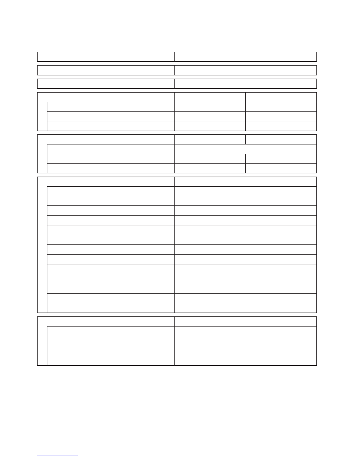
1. OPERATING RANGE
Temperature
Maximum
Minimum
Maximum
Minimum
Outdoor Air Intake Temp.
43˚C D.B.
19˚C D.B.
24˚C D.B./ 18˚C D.B.
-
/-15˚C W.B.
Indoor Air Intake Temp.
32˚C D.B./ 23˚C W.B.
19˚C D.B./ 14˚C W.B.
27˚C D.B.
16˚C D.B.
Cooling
Heating
2
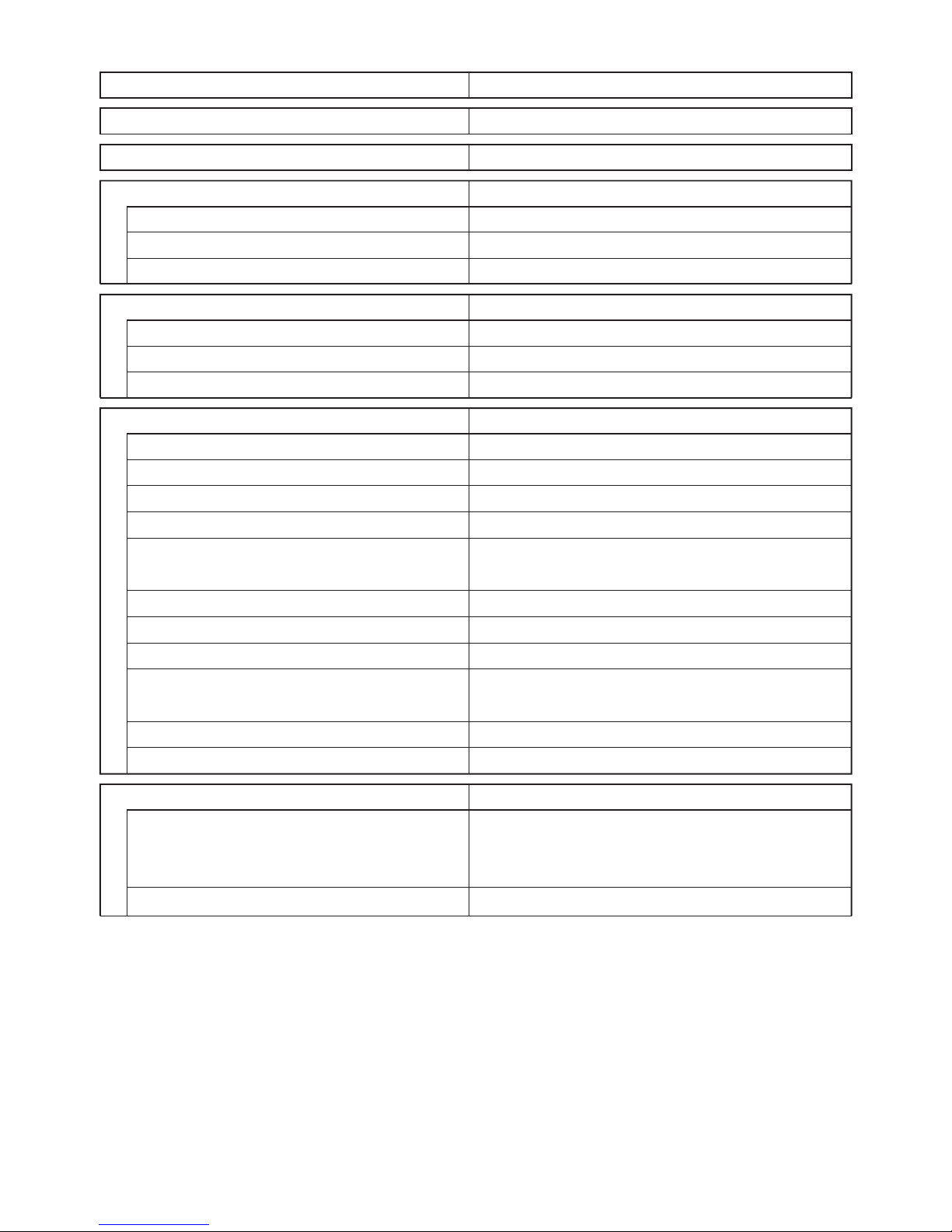
2. SPECIFICATIONS
Indoor Unit
2-1. Unit Specifications
SAP-KRV243GJH
Features
Controls/Temperature control
Control unit
Timer
Fan speeds
Airflow direction (Indoor) Horizontal
Vertical
Air filter
Operation sound Hi/Lo dB-A
Refrigerant tubing connections
Refrigerant Narrow tube mm(in.)
tube diameter Wide tube mm(in.)
Refrigerant
Refrigerant tube kit
Microprocessor / I.C. thermostat
Wireless remote control unit
ON/OFF 24 hours & Daily program, 1- hour OFF
3 and Auto
Manual
Auto
Washable, Anti-Mold
47/38
Flare type
6.35(1/4)
12.7(1/2)
R410A
Optional
Dimensions & Weight
Unit dimensions Height mm
Width mm
Depth mm
Net Weight Kg
330
1,140
228
18
Performance
Capacity kW
Air circulation (Hi) L/S
Moisture removal (High) Liters/h
Cooling
0.6-7.9
305
4.0
Heating
0.8-9.6
325
-
Electrical Rating
Available voltage range V
Running amperes A
Power input W
Cooling
8.5
1950
Heating
12.7
2920
216~264
Type
Wall mounted type indoor unit
Power Source
240V~50Hz
Voltage rating
240V
DATA SUBJECT TO CHANGE WITHOUT NOTICE.
3
Indoor Unit SAP-KRV243GJ
Features
Controls/Temperature control
Control unit
Timer
Fan speeds
Airflow direction (Indoor) Horizontal
Vertical
Air filter
Operation sound Hi/Lo dB-A
Refrigerant tubing connections
Refrigerant Narrow tube mm(in.)
tube diameter Wide tube mm(in.)
Refrigerant
Refrigerant tube kit
Microprocessor / I.C. thermostat
Wireless remote control unit
ON/OFF 24 hours & Daily program, 1- hour OFF
3 and Auto
Manual
Auto
Washable, Anti-Mold
47/38
Flare type
6.35(1/4)
12.7(1/2)
R410A
Optional
Dimensions & Weight
Unit dimensions Height mm
Width mm
Depth mm
Net Weight Kg
330
1,140
228
18
Performance
Capacity kW
Air circulation (Hi) L/S
Moisture removal (High) Liters/h
Cooling
0.6-7.9
305
4.0
Electrical Rating
Available voltage range V
Running amperes A
Power input W
Cooling
216~264
8.5
1950
Type
Wall mounted type indoor unit
Power Source
240V~50Hz
Voltage rating
240V
DATA SUBJECT TO CHANGE WITHOUT NOTICE.
4
Indoor Unit SAP-KRV303GJH
Features
Controls/Temperature control
Control unit
Timer
Fan speeds
Airflow direction (Indoor) Horizontal
Vertical
Air filter
Operation sound Hi/Lo dB-A
Refrigerant tubing connections
Refrigerant Narrow tube mm(in.)
tube diameter Wide tube mm(in.)
Refrigerant
Refrigerant tube kit
Microprocessor / I.C. thermostat
Wireless remote control unit
ON/OFF 24 hours & Daily program, 1- hour OFF
3 and Auto
Manual
Auto
Washable, Anti-Mold
47/38
Flare type
6.35(1/4)
15.88(5/8)
R410A
Optional
Dimensions & Weight
Unit dimensions Height mm
Width mm
Depth mm
Net Weight kg
330
1,140
228
18
Performance
Capacity kW
Air circulation (Hi) L/S
Moisture removal (High) Liters/h
Heating
1.7-10.4
325
*
Electrical Rating
Available voltage range V
Running amperes A
Power input W
Heating
12.4
2920
Type
Wall mounted type indoor unit
Power Source
Voltage rating
240V
DATA SUBJECT TO CHANGE WITHOUT NOTICE.
Cooling
1.2-9.3
305
4.5
Cooling
11.3
2650
240V~50Hz
216~264
5
Indoor Unit SAP-KRV303GJ
Features
Controls/Temperature control
Control unit
Timer
Fan speeds
Airflow direction (Indoor) Horizontal
Vertical
Air filter
Operation sound Hi/Lo dB-A
Refrigerant tubing connections
Refrigerant Narrow tube mm(in.)
tube diameter Wide tube mm(in.)
Refrigerant
Refrigerant tube kit
Microprocessor / I.C. thermostat
Wireless remote control unit
ON/OFF 24 hours & Daily program, 1- hour OFF
3 and Auto
Manual
Auto
Washable, Anti-Mold
47/38
Flare type
6.35(1/4)
15.88(5/8)
R410A
Optional
Dimensions & Weight
Unit dimensions Height mm
Width mm
Depth mm
Net Weight kg
330
1,140
228
18
Performance
Capacity kW
Air circulation (Hi) L/S
Moisture removal (High) Liters/h
Cooling
1.2-9.3
305
4.5
Electrical Rating
Available voltage range V
Running amperes A
Power input W
Cooling
216~264
11.3
2650
Type
Wall mounted type indoor unit
Power Source
240V~50Hz
Voltage rating
240V
DATA SUBJECT TO CHANGE WITHOUT NOTICE.
6
Indoor Unit
2-2. Major Component Specifications
SAP-KRV243GJH
Control PCB
Part No.
Controls
Control circuit fuse
POW-KMRV243GJ
Microprocessor
2.50V 3.15A
Remote Control Unit
RCS-3MVHPS4E
Flap Motor and Louver Motor
Type
Model
Rating
Coil resistance (Ambient temp. 20˚C) Ω
Stepping motor
MP24GA2...2
DC 12V
Each terminal (1-2, 1-3, 1-4, 1-5): 400*7%
DATA SUBJECT TO CHANGE WITHOUT NOTICE.
Heat Exchanger Coil
Coil
Rows
Fin pitch mm
Face area m
2
Aluminum plate fin/Copper tube
2
1.3
0.214
Fan & Fan Motor
Type Fan/Fan motor
Q'ty...Dia. and length mm
Fan motor model...Q'ty
No. of poles...rpm (220V, High)
Nominal output W
Coil resistance (Ambient temp. 20˚C) Ω
Safety devices Type
Operating temp. Open ˚C
Close ˚C
Run capacitor µF
VAC
Cross-flow /AC motor
1... D100
KFG4X-31B6P-S...1
4...1269
30
Thermal protector
130*8
79*15
1.5
480
BRN-WHT: 161.2
WHT-VLT : 11.6
VLT-ORG : 68.7
ORG-YEL: 26.9
YEL-BLK : 22.8
BLK-PNK : 115.2
7
Indoor Unit SAP-KRV243GJ
Control PCB
Part No.
Controls
Control circuit fuse
POW-KMRV243GJ
Microprocessor
2.50V 3.15A
Remote Control Unit
RCS-3MVPS4E
Flap Motor and Louver Motor
Type
Model
Rating
Coil resistance (Ambient temp. 20˚C) Ω
Stepping motor
MP24GA2...2
DC 12V
Each terminal (1-2, 1-3, 1-4, 1-5): 400*7%
DATA SUBJECT TO CHANGE WITHOUT NOTICE.
Heat Exchanger Coil
Coil
Rows
Fin pitch mm
Face area m
2
Aluminum plate fin/Copper tube
2
1.3
0.214
Fan & Fan Motor
Type Fan/Fan motor
Q'ty...Dia. and length mm
Fan motor model...Q'ty
No. of poles...rpm (220V, High)
Nominal output W
Coil resistance (Ambient temp. 20˚C) Ω
Safety devices Type
Operating temp. Open ˚C
Close ˚C
Run capacitor µF
VAC
Cross-flow /AC motor
1... D100
KFG4X-31B6P-S...1
4...1269
30
Thermal protector
130*8
79*15
1.5
480
BRN-WHT: 161.2
WHT-VLT : 11.6
VLT-ORG : 68.7
ORG-YEL: 26.9
YEL-BLK : 22.8
BLK-PNK : 115.2

8
Indoor Unit SAP-KRV303GJH
Control PCB
Part No.
Controls
Control circuit fuse
POW-KMRV243GJ
Microprocessor
2.50V 3.15A
Remote Control Unit
RCS-3MVHPS4E
Flap Motor and Louver Motor
Type
Model
Rating
Coil resistance (Ambient temp. 20˚C) Ω
Stepping motor
MP24GA2...2
DC 12V
Each terminal (1-2, 1-3, 1-4, 1-5): 400*7%
DATA SUBJECT TO CHANGE WITHOUT NOTICE.
Heat Exchanger Coil
Coil
Rows
Fin pitch mm
Face area m
2
Aluminum plate fin/Copper tube
2
1.3
0.214
Fan & Fan Motor
Type Fan/Fan motor
Q'ty...Dia. and length mm
Fan motor model...Q'ty
No. of poles...rpm (220V, High)
Nominal output W
Coil resistance (Ambient temp. 20˚C) Ω
Safety devices Type
Operating temp. Open ˚C
Close ˚C
Run capacitor µF
VAC
Cross-flow /AC motor
1... D100
KFG4X-31B6P-S...1
4...1269
30
Thermal protector
130*8
79*15
1.5
480
BRN-WHT: 161.2
WHT-VLT : 11.6
VLT-ORG : 68.7
ORG-YEL: 26.9
YEL-BLK : 22.8
BLK-PNK : 115.2

9
Indoor Unit SAP-KRV303GJ
Control PCB
Part No.
Controls
Control circuit fuse
POW-KMRV243GJ
Microprocessor
2.50V 3.15A
Remote Control Unit
RCS-3MVPS4E
Flap Motor and Louver Motor
Type
Model
Rating
Coil resistance (Ambient temp. 20˚C) Ω
Stepping motor
MP24GA2...2
DC 12V
Each terminal (1-2, 1-3, 1-4, 1-5): 400*7%
DATA SUBJECT TO CHANGE WITHOUT NOTICE.
Heat Exchanger Coil
Coil
Rows
Fin pitch mm
Face area m
2
Aluminum plate fin/Copper tube
2
1.3
0.214
Fan & Fan Motor
Type Fan/Fan motor
Q'ty...Dia. and length mm
Fan motor model...Q'ty
No. of poles...rpm (220V, High)
Nominal output W
Coil resistance (Ambient temp. 20˚C) Ω
Safety devices Type
Operating temp. Open ˚C
Close ˚C
Run capacitor µF
VAC
Cross-flow /AC motor
1... D100
KFG4X-31B6P-S...1
4...1269
30
Thermal protector
130*8
79*15
1.5
480
BRN-WHT: 161.2
WHT-VLT : 11.6
VLT-ORG : 68.7
ORG-YEL: 26.9
YEL-BLK : 22.8
BLK-PNK : 115.2
10
Indoor Unit
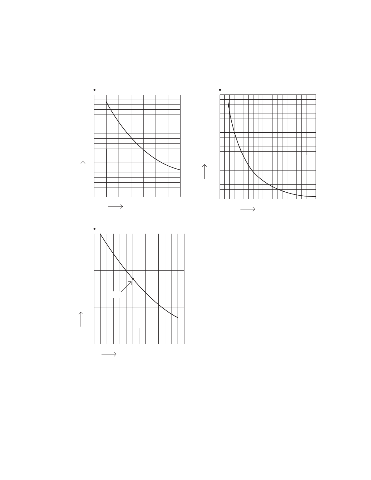
2-3. Other Component Specifications
SAP-KRV243GJH
SAP-KRV243GJ
SAP-KRV303GJH
SAP-KRV303GJ
1000
100
10
1
Humidity sensor
Resistance (Ω)
Relative humidity (%)
30354045505560657075808590
25˚C
200
180
160
140
120
100
80
60
40
20
0
Indoor heat exchanger sensor
Resistance (Ω)
Temperature (˚C)
0 10 20 30 40 50 60 70 80 90
10
9
8
7
6
5
4
3
2
1
Indoor air temp sensor
Resistance (Ω)
Temperature (˚C)
10 15 20 25 30 35 40

11
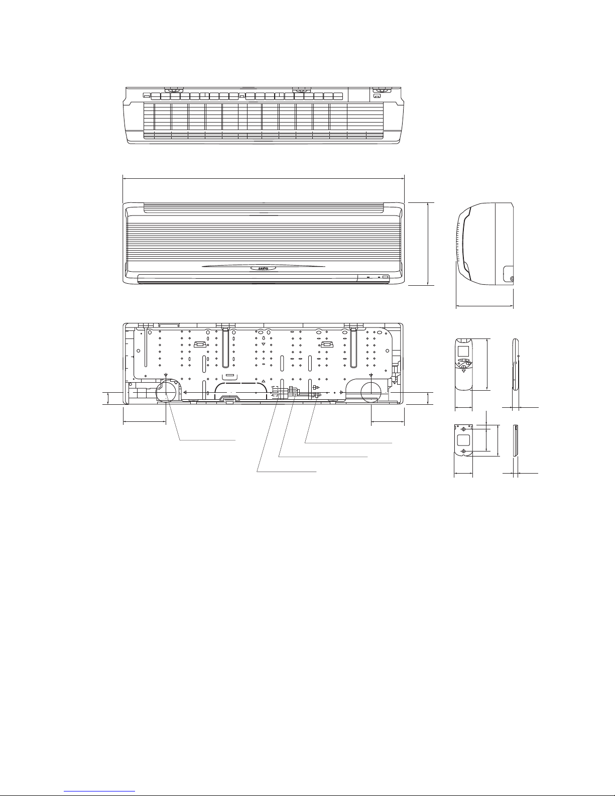
3. DIMENSIONAL DATA
Indoor Unit SAP-KRV243GJH
unit: mm
1,140
330
228
61 23
182
65
14.3
78 15
110
Remote control unit
48
135
Narrow tube ø6.35(1/4")
Wide tube ø12.7(1/2")
Drain hose ø18
174
Center of tubing
hole(2 places)
48

12
Indoor Unit SAP-KRV243GJ
unit: mm
1,140
330
228
61 23
182
65
14.3
78 15
110
Remote control unit
48
135
Narrow tube ø6.35(1/4")
Wide tube ø12.7(1/2")
Drain hose ø18
174
Center of tubing
hole(2 places)
48
13
Indoor Unit SPA-KRV303GJH
unit: mm
1,140
330
228
61 23
182
65
14.3
78 15
110
Remote control unit
48
135
Narrow tube ø6.35(1/4")
Wide tube ø15.88(5/8")
Drain hose ø18
174
Center of tubing
hole(2 places)
48

14
Indoor Unit SAP-KRV303GJ
unit: mm
1,140
330
228
61 23
182
65
14.3
78 15
110
Remote control unit
48
135
Narrow tube ø6.35(1/4")
Wide tube ø15.88(5/8")
Drain hose ø18
174
Center of tubing
hole(2 places)
48
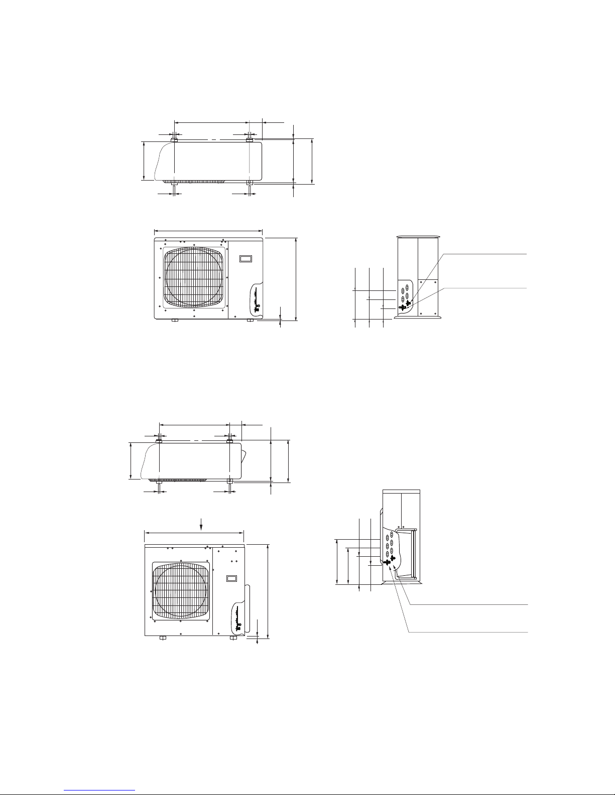
15
Outer Dimensions of Outdoor Unit
CRV303GJ/GJH
CRV243GJ/GJH
940
18
730
246
166
86
Service valve on narrow
tube side
(Outer diameter Ø 6.35)
Service valve on wide
tube side
(Outer diameter Ø 12.7)
110
1313
10380
405
15
13 13
340
660
110
1313
10380
405
15
13 13
340
660
A
416
336
256
176
Service valve on wide tube side
(Outer diameter Ø 15.88)
Service valve on narrow tube side
(Outer diameter Ø 6.35)
940
880
25
A
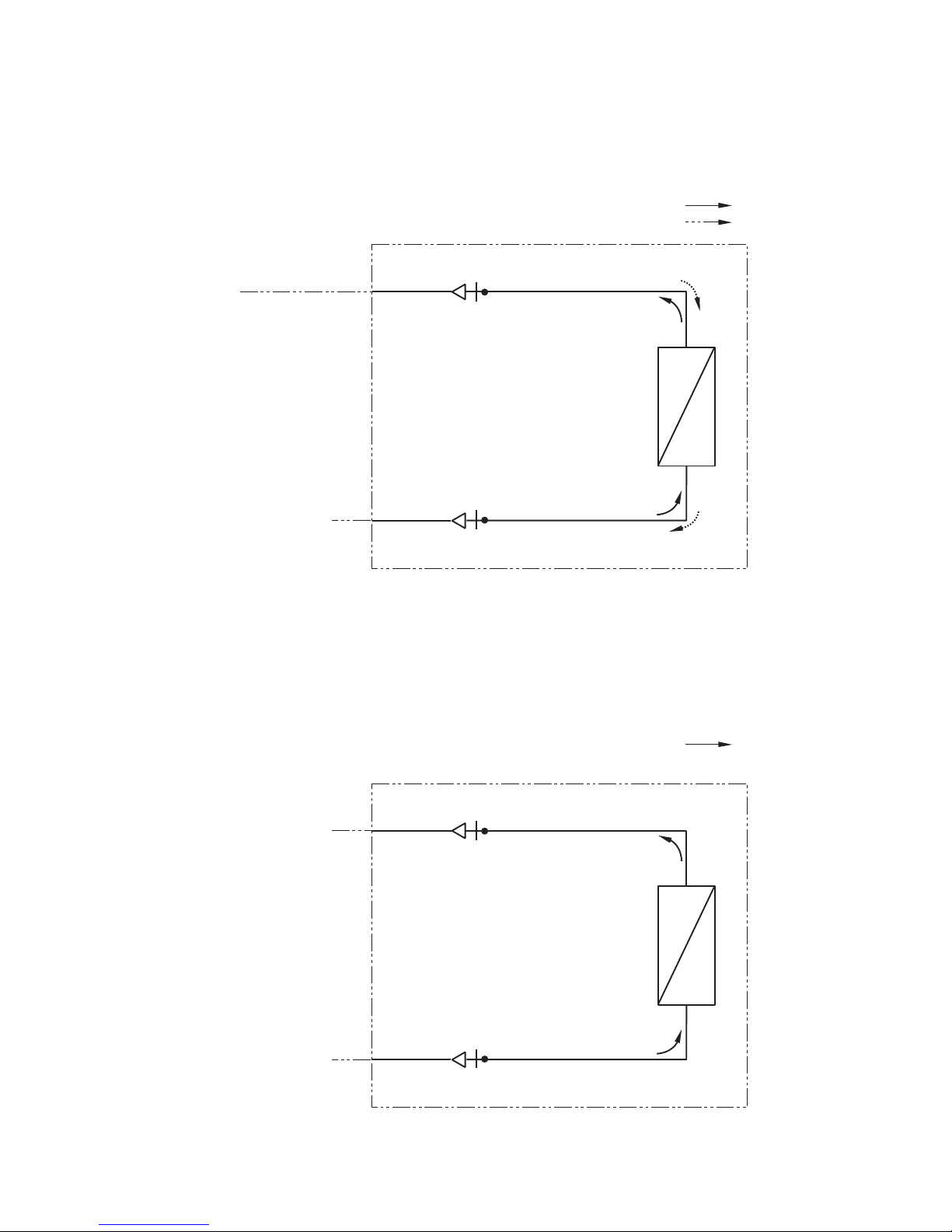
4. REFRIGERANT FLOW DIAGRAM
Indoor Unit SAP-KRV243GJH
SAP-KRV303GJH
Indoor unit
Indoor heat
exchanger
ø12.7 (KRV243GJH)
ø15.88 (KRV303GJH)
ø6.35
Cooling
Heating
Indoor Unit SAP-KRV243GJ
SAP-KRV303GJ
Indoor unit
Indoor heat
exchanger
ø6.35
Cooling
16
EC
P
EC
P
ø12.7 (KRV243GJ)
ø15.88 (KRV303GJ)
17
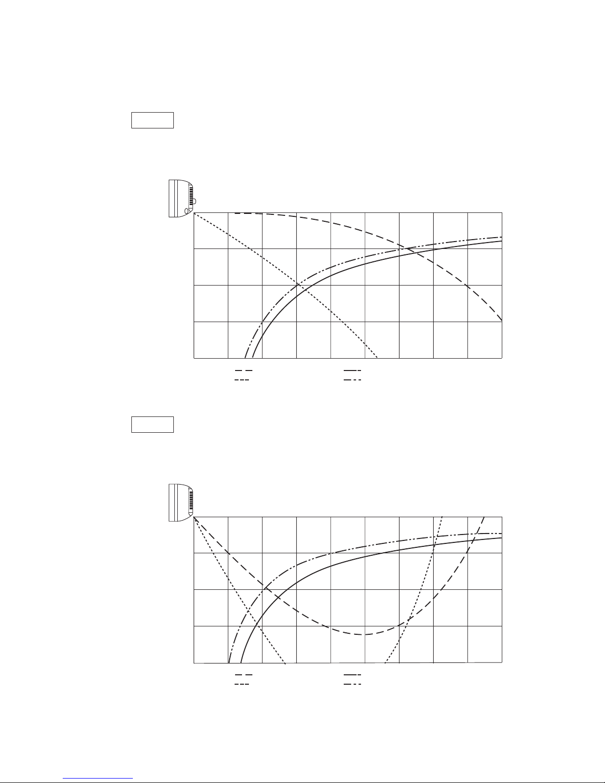
5. PERFORMANCE DATA
5-1. Air Throw Distance Chart
Indoor Unit SAP-KRV243GJH
Cooling
Room air temp.
Fan speed
: 27˚C
: High
1
2
3
4
Horizontal distance (m)
Axis air velocity (m/s)
Vertical distance(m)
1 2 3 4 5 6 7 8 9
: Flap angle 0˚ ,
: Flap angle 30˚,
: Axis air velocity 0˚
: Axis air velocity 30˚
Heating
Room air temp.
Fan speed
: 20˚C
: High
1
2
3
4
Horizontal distance (m)
Axis air velocity (m/s)
Vertical distance(m)
1 2 3 4 5 6 7 8 9
: Flap angle 45˚ ,
: Flap angle 60˚,
: Axis air velocity 45˚
: Axis air velocity 60˚
18
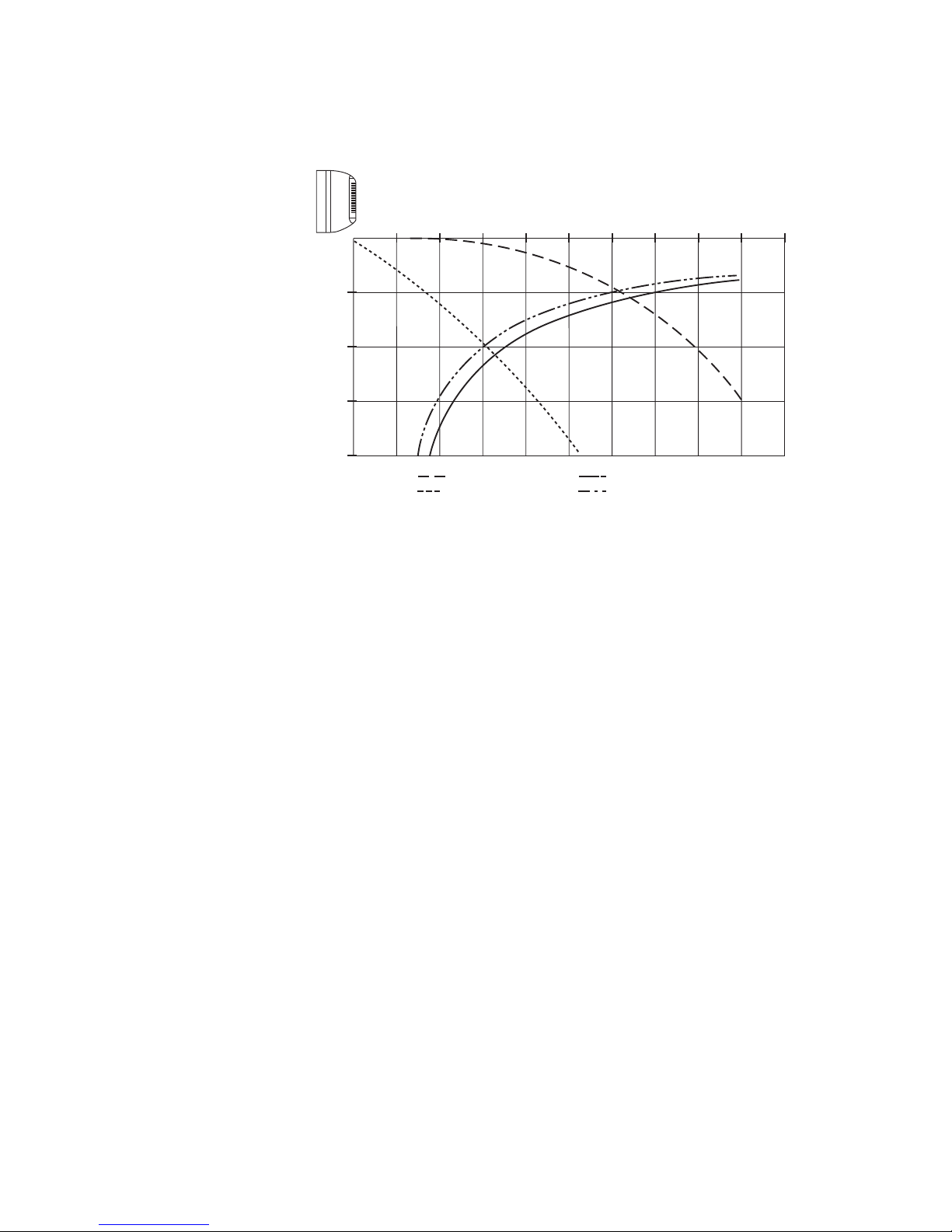
Indoor Unit SAP-KRV243GJ
Room air temp.
Fan speed
: 27˚C
: High
1
2
3
4
Horizontal distance (m)
Axis air velocity (m/s)
Vertical distance(m)
1 2 3 4 5 6 7 8 9
: Flap angle 0˚ ,
: Flap angle 30˚,
: Axis air velocity 0˚
: Axis air velocity 30˚
10

19
Indoor Unit SAP-KRV303GJH
Cooling
Room air temp.
Fan speed
: 27˚C
: High
1
2
3
4
Horizontal distance (m)
Axis air velocity (m/s)
Vertical distance(m)
1 2 3 4 5 6 7 8 9
: Flap angle 0˚ ,
: Flap angle 30˚,
: Axis air velocity 0˚
: Axis air velocity 30˚
Heating
Room air temp.
Fan speed
: 20˚C
: High
1
2
3
4
Horizontal distance (m)
Axis air velocity (m/s)
Vertical distance(m)
1 2 3 4 5 6 7 8 9
: Flap angle 45˚ ,
: Flap angle 60˚,
: Axis air velocity 45˚
: Axis air velocity 60˚

20
Indoor Unit SAP-KRV303GJ
Room air temp.
Fan speed
: 27˚C
: High
1
2
3
4
Horizontal distance (m)
Axis air velocity (m/s)
Vertical distance(m)
1 2 3 4 5 6 7 8 9
: Flap angle 0˚ ,
: Flap angle 30˚,
: Axis air velocity 0˚
: Axis air velocity 30˚
10
21
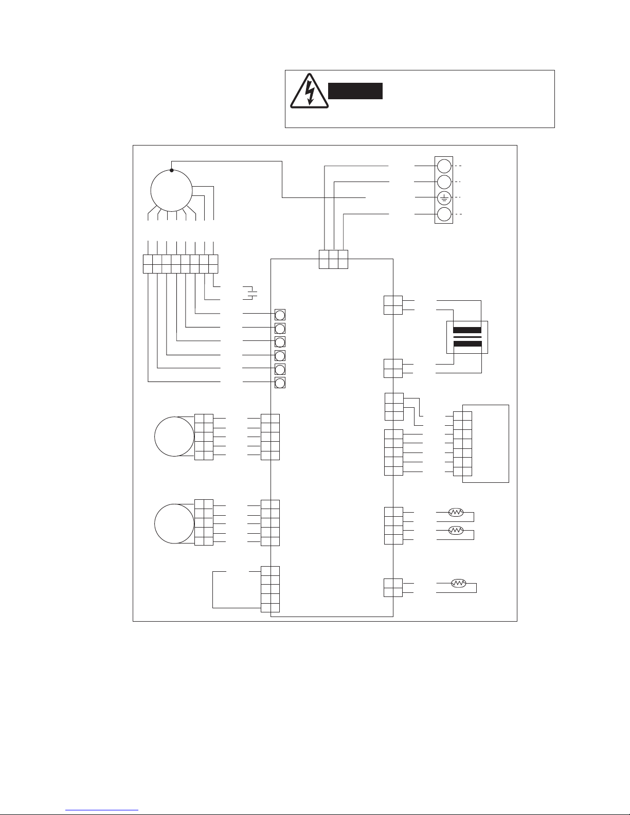
6. ELECTRICAL DATA
Indoor Unit
6-1. Electrical Characteristics
SAP-KRV243GJH
WARNING
To avoid electrical shock hazard, be
sure to disconnect power before
checking, servicing andlor cleaning
any electrical parts.
W
W
W
W
W
W
WHT
GRY
GRY
GRY
GRY
Controller
Room thermistor
Room/Coil
4P (WHT)
HUM
2P (Red)
BLK
BLK
BLK
BLK
Coil thermistor
Humidity sensor
BLK
BLK
BRN
BRN
S
WHT
WHT
P
Power transformer
IND lamp assy
1 1
2 2
3 3
4 4
5 5
1 1
2 2
3 3
4 4
5 5
FLP
WHT
BLU
BLU
BLU
BLU
Flap 1
5P (WHT)
Flap motor (Upper)
FLP
WHT
BLU
BLU
BLU
BLU
Flap 2
5P (BLK)
Flap motor (Lower)
BLK
R.IN
5P (BLK)
WHT
GRY
Fan motor
FM
8 7 6 5 4 3 2 1
8 7 6 5 4 3 2 1
1 3 5
1 3 5
1 1
3 3
1 1
2 2
3 3
1 1
2 2
3 3
4 4
5 5
1 1
2 2
3 3
4 4
5 5
1 1
2 2
3 3
4
4
5 5
1 1
2 2
3 3
4 4
5 5
1 1
2 2
3 3
4 4
1 1
2 2
1 1
2 2
1 1
2 2
3 3
4 4
5 5
6 6
7 7
1
2
4
BLK
GRN/YEL
WHT
Terminal
Plate
From Outdoor Unit
BLK
YEL
ORG
VLT
WHT
GRY
BRN
PNK
Capacitor
WHT
Connector
(WHT)
PNK
BRN
GRY
WHT
VLT
ORG
YEL
BLK
SUP
5P(BLK)
Trans-P
3P(WHT)
FM
HH
H
M
L
LL
Trans-S
2P(WHT)
Lamp.1
5P(WHT)
5P(WHT)
Lamp.2
Connector
(WHT) (WHT) (WHT)
Connector
(WHT) (GRN) (BLK)
 Loading...