

Sanyo SAP-K77RAX User Manual
TECHNICAL & SERVICE MANUAL
SAP-K77RAX + SAP-C77RAX
SAP-K97RAX + SAP-C97RAX
SAP-K127RAX + SAP-C127RAX
SPLIT SYSTEM AIR CONDITIONER
Indoor Model No.
SAP-K77RAX
SAP-K97RAX
SAP-K127RAX
Indoor Unit
Product Code No.
1 852 350 01
1 852 350 02
1 852 350 03
Outdoor Model No.
SAP-C77RAX
SAP-C97RAX
SAP-C127RAX
FILE NO.
Destination: Russia (50Hz)
Product Code No.
1 852 350 04
1 852 350 05
1 852 350 06
Outdoor Unit
SAP-K77RAX
SAP-K97RAX
SAP-K127RAX
SAP-C77RAX
SAP-C97RAX
SAP-C127RAX
REFERENCE NO. SM700754
When Wiring
ELECTRICAL SHOCK CAN CAUSE
SEVERE PERSONAL INJURY OR DEATH.
ONLY A QUALIFIED, EXPERIENCED
ELECTRICIAN SHOULD ATTEMPT TO
WIRE THIS SYSTEM.
SPECIAL PRECAUTIONS
This symbol refers to a hazard
or unsafe practice which can
result in severe personal
injury or death.
This symbol refers to a hazard
or unsafe practice which can
result in personal injury or
product or property damage.
CAUTION
CAUTION
WARNING
WARNING
Important!
Please Read Before Starting
This air conditioning system meets strict safety and
operating standards. As the installer or service person, it
is an important part of your job to install or service the
system so it operates safely and efficiently.
For safe installation and trouble-free operation, you
must:
Carefully read this instruction booklet before beginning.
Follow each installation or repair step exactly as shown.
Observe all local, state, and national electrical codes.
Pay close attention to all warning and caution notices
given in this manual.
If Necessary, Get Help
These instructions are all you need for most installation
sites and maintenance conditions. If you require help for
a special problem, contact our sales/service outlet or
your certified dealer for additional instructions.
In Case of Improper Installation
The manufacturer shall in no way be responsible for
improper installation or maintenance service, including
failure to follow the instructions in this document.
Do not supply power to the unit until all wiring and
tubing are completed or reconnected and checked.
Highly dangerous electrical voltages are used in this
system. Carefully refer to the wiring diagram and these
instructions when wiring. Improper connections and
inadequate grounding can cause accidental injury or
death.
Ground the unit following local electrical codes.
Connect all wiring tightly. Loose wiring may cause
overheating at connection points and a possible fire
hazard.
Install a protective leakage breaker depending on the
installation location (especially a damp or humid
location). If a leakage breaker is not installed, electric
shock can occur.
When Transporting
Be careful when picking up and moving the indoor and
outdoor units. Get a partner to help, and bend your knees
when lifting to reduce strain on your back. Sharp edges or
thin aluminum fins on the air conditioner can cut your
fingers.
When Installing
In a Ceiling or Wall
Make sure the ceiling/wall is strong enough to hold the
unit’s weight. It may be necessary to construct a strong
wood or metal frame to provide added support.
In a Room
Properly insulate any tubing run inside a room to prevent
"sweating" that can cause dripping and water damage to
walls and floors.
In Moist or Uneven Locations
Use a raised concrete pad or concrete blocks to provide a
solid, level foundation for the outdoor unit. This prevents
water damage and abnormal vibration.
In an Area with High Winds
Securely anchor the outdoor unit down with bolts and a
metal frame. Provide a suitable air baffle.
In a Snowy Area (for Heat Pump-type Systems)
Install the outdoor unit on a raised platform that is higher
than drifting snow. Provide snow vents.
When Connecting Refrigerant Tubing
Use the flare method for connecting tubing.
Apply refrigerant lubricant to the matching surfaces of
the flare and union tubes before connecting them, then
tighten the nut with a torque wrench for a leak-free
connection.
Check carefully for leaks before starting the test run.
When Servicing
Tu rn the power off at the main power box (mains) before
opening the unit to check or repair electrical parts and
wiring.
Keep your fingers and clothing away from any moving
parts.
Clean up the site after you finish, remembering to check
that no metal scraps or bits of wiring have been left
inside the unit being serviced.
Others
Ventilate any enclosed areas when installing or testing
the refrigeration system. Escaped refrigerant gas, on
contact with fire or heat, can produce dangerously toxic
gas.
Confirm upon completing installation that no refrigerant
gas is leaking. If escaped gas comes in contact with a
stove, gas water heater, electric room heater or other
heat source, it can produce dangerously toxic gas.
•
•
•
•
•
•
•
•
•
•
•
•
•
2

Table of Contents
1. OPERATING RANGE
2. SPECIFICATIONS
2-1. Unit Specifications
2-2. Major Component Specifications
2-3. Other Component Specifications
3. DIMENSIONAL DATA
4. REFRIGERANT FLOW DIAGRAM
4-1. Refrigerant Flow Diagram
5. PERFORMANCE DATA
5-1. Performance charts
5-2. Air Throw Distance Charts
5-3. Cooling Capacity
6. ELECTRICAL DATA
6-1. Electrical Characteristics
6-2. Electric Wiring Diagrams
7. INSTALLATION INSTRUCTIONS
7-1. Installation Site Selection
7-2. Recommended Wire Length and Diameter
7-3. Remote Control Unit Installation Position
7-4. How to Test Run the Air Conditioner
7-5. Removing and Installing the Grille
7-6. Address Setting of the Remote Control Unit
8. FUNCTIONS
8-1. Room Temperature Control
8-2. Dry Operation (Dehumidification)
8-3. Freeze Prevention (Cooling and Dry)
8-4. Automatic Fan Speed (Cooling and Dry)
5
6
9
15
16
19
20
23
26
29
30
32
34
35
36
37
38
39
40
41
42
...................................................................................................................
.............................................................................................................
.......................................................................................
.......................................................................................
.....................................................................................................................
...................................................................................................
............................................................................................................
.................................................................................................
................................................................................................................
....................................................................................................
....................................................................................................
...................................................................................................
........................................................................
...........................................................................
...................................................................................
......................................................................................
.......................................................................
................................................................................................
.......................................................................................
..................................................................................
.............................................................................
Page
3

9. TROUBLESHOOTING
9-1. Check before and after troubleshooting
9-2. Air conditioner does not operate.
9-3. Some part of air conditioner does not operate.
9-4. Air conditioner operates, but abnormalities are observed.
10. CHECKING ELECTRICAL COMPONENTS
10-1. Measurement of Insulation Resistance
10-2. Checking Continuity of Fuse on PCB Ass'y
10-3. Checking Motor Capacitor
APPENDIX INSTRUCTION MANUAL
43
44
48
50
51
52
52
53
................................................................................
...........................................................................................
.....................................................................
....................................................
...............................................................................
........................................................................
..................................................................................................
...........................................................................................
Page
4

1. OPERATING RANGE
Maximum
Minimum
32 °C D.B. / 23 °C W.B.
19 °C D.B. / 14 °C W.B.
43 °C D.B.
19 °C D.B.
Temperature Indoor Air Intake Temp. Outdoor Air Intake Temp.
Cooling
5

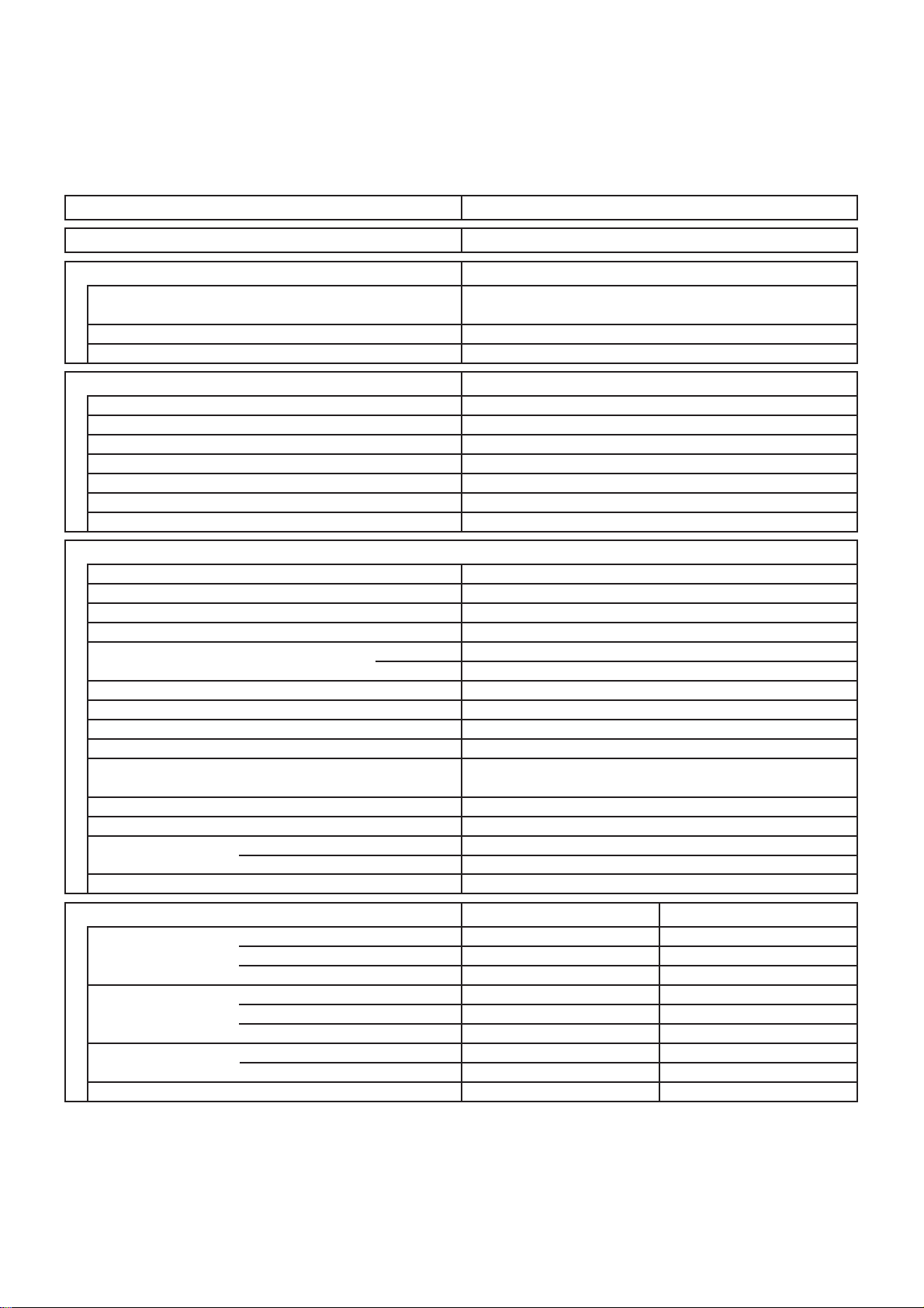
2. SPECIFICATIONS
6
2-1. Unit Specifications
Indoor Unit SAP-K77RAX
Outdoor Unit SAP-C77RAX
Power Source
Voltage Rating
Performance
Capacity
Air Circulation (High)
Moisture Removal (High)
Electrical Rating
Available Voltage Range
Running Amperes
C.O.P.
Compressor Locked Rotor Amperes
Features
Controls / Temperature Control
Control Unit
Timer
Indoor / Outdoor Fan Speeds
Airflow Direction (Indoor) Horizontal
Air Filter
Compressor
Refrigerant / Amount charged at shipment kg
Refrigerant Control
Operation Sound
Refrigerant Tubing Connections
Refrigerant mm (in.)
Refrigerant Tube Kit / Accessories
Indoor : Hi/Me/Lo
Outdoor : Hi
Narrow tube
Wide tube
220 to 240V Single-Phase 50Hz
220-240 V
Cooling
kW
BTU/h
3
m
/h
Liters/h
V
A
WPower Input
%Power Factor 97 / 93 / 91
W/W.R.E.E 2.80 / 2.73 / 2.66
W/W
A 16.5
Microprocessor / I.C. Thermister
12-Hour ON or OFF Timer, 1Hour OFF Timer
Vertical
dB-A
dB-A
mMax. allowable tubing length at shipment
).ni( mmretemaiD ebuT
2.10 / 2.10 / 2.10
7,200 / 7,200 / 7,200
Cooling
198 to 264
3.5 / 3.6 / 3.6
750 / 770 / 790
Wireless Remote Control Unit
Auto and 3 steps / 1 (Hi)
Washable, Anti-Mold
Single Rotary
R22 / 0.48
Capillary tube
38 / 33 / 30
Flare Type
6.35 (1/4)
9.52 (3/8)
Optional / Air Clean Filter
430
1.1
-
Manual
Auto
49
5
Dimensions & Weight
Unit Dimensions Height
Width
Depth
Package Dimensions
Weight
Shipping Volume
Remarks: Rating conditions are:
Cooling: Indoor air temperature 27°C D.B. / 19°C W.B.
Outdoor air temperature 35°C D.B. / 24°C W.B.
Height
Width
Depth
Net
Shipping
mm
mm
mm
mm
mm
mm
kg
kg
m
Outdoor UnitIndoor Unit
644052
799
205
270
870
295
7.5
9.0
3
0.06
DATA SUBJECT TO CHANGE WITHOUT NOTICE.
660
240
491
775
340
21
22
0.13
Indoor Unit SAP-K97RAX
7
Outdoor Unit SAP-C97RAX
Power Source
Voltage Rating
Performance
Capacity
Air Circulation (High)
Moisture Removal (High)
Electrical Rating
Available Voltage Range
Running Amperes
C.O.P.
Compressor Locked Rotor Amperes
Features
Controls / Temperature Control
Control Unit
Timer
Indoor / Outdoor Fan Speeds
Airflow Direction (Indoor) Horizontal
Air Filter
Compressor
Refrigerant / Amount charged at shipment kg
Refrigerant Control
Operation Sound
Indoor : Hi/Me/Lo
Outdoor : Hi
Refrigerant Tubing Connections
Refrigerant mm (in.)
Narrow tube
Wide tube
Refrigerant Tube Kit / Accessories
220 to 240V Single-Phase 50Hz
220-240 V
Cooling
kW
2.55 / 2.55 / 2.55
BTU/h
3
m
/h
Liters/h
Cooling
V
A
WPower Input
198 to 264
4.5 / 4.5 / 4.6
930 / 960 / 1,000
%Power Factor 94 / 93 / 91
W/W.R.E.E 2.74 / 2.66 / 2.55
W/W
A 22.5
Microprocessor / I.C. Thermister
Wireless Remote Control Unit
12-Hour ON or OFF Timer, 1Hour OFF Timer
Auto and 3 steps / 1 (Hi)
Vertical
Washable, Anti-Mold
Single Rotary
R22 / 0.53
Capillary tube
dB-A
39 / 34 / 31
dB-A
Flare Type
mMax. allowable tubing length at shipment
6.35 (1/4)
).ni( mmretemaiD ebuT
9.52 (3/8)
Optional / Air Clean Filter
8,700
440
1.8
-
Manual
Auto
50
5
Dimensions & Weight
Unit Dimensions Height
Width
Depth
Package Dimensions
Height
Width
Depth
Weight
Net
Shipping
Shipping Volume
Remarks: Rating conditions are:
Cooling: Indoor air temperature 27°C D.B. / 19°C W.B.
Outdoor air temperature 35°C D.B. / 24°C W.B.
mm
mm
mm
mm
mm
mm
kg
kg
m
Outdoor UnitIndoor Unit
644052
799
205
270
870
295
7.5
9.0
3
0.06
660
240
491
775
340
21
22
0.13
DATA SUBJECT TO CHANGE WITHOUT NOTICE.

Indoor Unit SAP-K127RAX
Outdoor Unit SAP-C127RAX
DATA SUBJECT TO CHANGE WITHOUT NOTICE.
Remarks: Rating conditions are:
Cooling: Indoor air temperature 27°C D.B. / 19°C W.B.
Outdoor air temperature 35°C D.B. / 24°C W.B.
Vertical
dB-A
dB-A
Indoor : Hi/Me/Lo
Outdoor : Hi
Air Filter
Compressor
Refrigerant / Amount charged at shipment kg
Refrigerant Control
6.1 / 6.1 / 6.2
1,265 / 1,305 / 1,345
3.55 / 3.55 / 3.55
12,100 / 12,100 / 12,100
Shipping Volume
Cooling
460
2.5
Cooling
Depth
Net
Shipping
Package Dimensions
Weight
Width
Depth
Height
Width
mm
kg
kg
m
3
mm
mm
mm
mm
220-240 V
mm
198 to 264
Dimensions & Weight
(*Qt = Quiet mode)
Refrigerant Tubing Connections
Unit Dimensions Height
Operation Sound
Electrical Rating
Air Circulation (High)
Moisture Removal (High)
WPower Input
V
A
Available Voltage Range
Running Amperes
Refrigerant Tube Kit / Accessories
Narrow tube
Wide tube
Refrigerant mm (in.)
).ni( mmretemaiD ebuT
0.14
28
295
7.5
340
27
9.0
0.06
555
775
799
205
660
240
270
870
Outdoor UnitIndoor Unit
015052
6.35 (1/4)
12.70 (1/2)
mMax. allowable tubing length at shipment
Flare Type
5
40 / 35 / 32
51
R22 / 0.72
Capillary tube
Washable, Anti-Mold
Single Rotary
Manual
Auto
Timer
Indoor / Outdoor Fan Speeds
12-Hour ON or OFF Timer, 1Hour OFF Timer
Auto and 3 steps / 1 (Hi)
Airflow Direction (Indoor) Horizontal
Controls / Temperature Control
Control Unit
Microprocessor / I.C. Thermister
Wireless Remote Control Unit
Features
C.O.P.
Compressor Locked Rotor Amperes
W/W
Optional / Air Clean Filter
kW
Performance
-
%Power Factor 94 / 93 / 90
A 33.5
Power Source
Voltage Rating
Liters/h
BTU/h
Capacity
m
3
/h
220 to 240V Single-Phase 50Hz
W/W.R.E.E
2.81 / 2.72 / 2.64
8

-
Control PCB
Control Circuit Fuse
Controls
Part No.
Microprocessor
250V 3.15A
CR-K77GAX
1 ... D102 / L637
RCS-7S2E-G
Cross-Flow
AC Motor
IBH-884-066B ... 1
4
BRN-WHT : 234
PNK (RED)-WHT : 209
12.5
1,280
Thermal fuse
130
1.5
450
DC 12V
Each Pair of Terminal : 200 +/- 7%
Stepping Motor
24BYJ48-916
Aluminum Plate Fin / Copper Tube
2
1.3
0.108
Fan
Remote Control Unit
Q'ty ... Dia. and Length
Type
mm
Fan Motor
Nominal Output
Coil Resistance
Rough Measure RPM (Cool)
Type
Model ... Q'ty
No. of Poles
Safety Device
Type
Operating Temp.
Close
Open °C
(Ambient Temp. 20 °C)
Run Capacitor (on controller PCB) Micro F
VAC
W
Ohm
Coil Resistance
Rating
Model
Flap Motor
Type
(Ambient Temp. 25 °C)
Ohm
Face Area
Coil
Rows
Fin Pitch
Heat Exchanger Coil
m
2
mm
DATA SUBJECT TO CHANGE WITHOUT NOTICE.
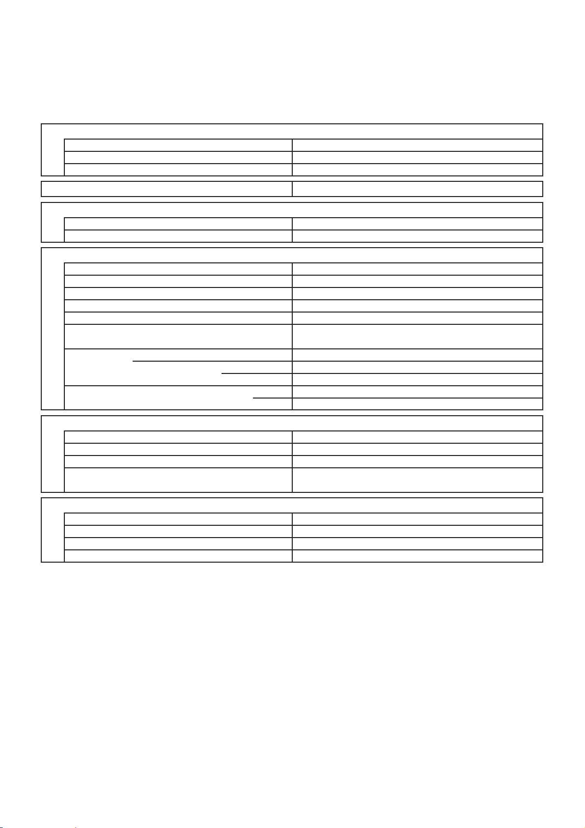
2-2. Major Component Specifications
2-2-1. Indoor Unit
Indoor Unit SAP-K77RAX
9

Control PCB
Control Circuit Fuse
Controls
Part No.
Microprocessor
250V 3.15A
CR-K97GAX
1 ... D102 / L637
RCS-7S2E-G
Cross-Flow
DC 12V
Each Pair of Terminal : 200 +/- 7%
Stepping Motor
24BYJ48-916
Aluminum Plate Fin / Copper Tube
2
1.3
0.108
Fan
Remote Control Unit
Q'ty ... Dia. and Length
Type
mm
Coil Resistance
Rating
Model
Flap Motor
Type
(Ambient Temp. 25 °C)
Ohm
Face Area
Coil
Rows
Fin Pitch
Heat Exchanger Coil
m
2
mm
DATA SUBJECT TO CHANGE WITHOUT NOTICE.
Indoor Unit SAP-K97RAX
-
AC Motor
IBH-884-066B ... 1
4
BRN-WHT : 234
PNK (RED)-WHT : 209
12.5
1,290
Thermal fuse
130
1.5
450
Fan Motor
Coil Resistance
Rough Measure RPM (Cool)
Type
Model ... Q'ty
No. of Poles
Safety Device
Type
Operating Temp.
Close
Open °C
(Ambient Temp. 20 °C)
Micro F
VAC
W
Ohm
Nominal Output
Run Capacitor (on controller PCB)
10
Control PCB
Control Circuit Fuse
Controls
Part No.
Microprocessor
250V 3.15A
CR-K127GAX
1 ... D102 / L637
RCS-7S2E-G
Cross-Flow
DC 12V
Each Pair of Terminal : 200 +/- 7%
Stepping Motor
24BYJ48-916
Aluminum Plate Fin / Copper Tube
2
1.1
0.162
Fan
Remote Control Unit
Q'ty ... Dia. and Length
Type
mm
Coil Resistance
Rating
Model
Flap Motor
Type
(Ambient Temp. 25 °C)
Ohm
Face Area
Coil
Rows
Fin Pitch
Heat Exchanger Coil
m
2
mm
DATA SUBJECT TO CHANGE WITHOUT NOTICE.
Indoor Unit SAP-K127RAX
-
AC Motor
IBH-884-066B ... 1
4
BRN-WHT : 234
PNK (RED)-WHT : 209
12.5
1,300
Thermal fuse
130
1.5
450
Fan Motor
Coil Resistance
Rough Measure RPM (Cool)
Type
Model ... Q'ty
No. of Poles
Safety Device
Type
Operating Temp.
Close
Open °C
(Ambient Temp. 20 °C)
Micro F
VAC
W
Ohm
Nominal Output
Run Capacitor (on controller PCB)
11

Control PCB
2-2-2. Outdoor Unit
Outdoor Unit SAP-C77RAX
DATA SUBJECT TO CHANGE WITHOUT NOTICE.
CC
BRN - WHT : 213
RED (PNK) - WHT : 168
Micro F
VAC
External Finish Acrylic baked-on enamel finish
SAY-56T ... 350
2.0
75
450
110
Thermal protector
Aluminum Plate Fin / Copper Tube
1
1.4
Face Area
m
2
0.227
Coil
Rows
mmhctiP niF
Heat Exchanger Coil
IB-976-501E ... 1
Compressor Oil ... Amount
6
25
890
Ohm
AC Motor
Type
Compressor Model / Nominal Output
Compressor
Coil Resistance (Ambient Temp. 25 °C)
Ohm
Single Rotary
C-1R65H5S / 650W
C - R : 4.68
C - S : 6.77
Overload Relay
Operating Temp.
Operating Amp. (Ambient Temp. 25 °C)
Safety Device Type
°C
°C
Open
Close
Micro F
VAC
Run Capacitor
Crankcase Heater
MRA99094-9201
External (OLR)
150 +/-5
69 +/-11
20
Trip in 6 to 16 sec. at 15A
400
-
1 ... D320
Fan
Propeller
mm.aiD ... yt'Q
Type
Open °C
°C
Operating Temp.
Type
Close
(Ambient Temp. 20 °C)
Fan Motor
Nominal Output
Coil Resistance
Safety Device
Rough Measure RPM (Cool)
Run Capacitor
Type
Model ... Q'ty
No. of Poles
W
12

Control PCB
Outdoor Unit SAP-C97RAX
DATA SUBJECT TO CHANGE WITHOUT NOTICE.
CC
BRN - WHT : 213
RED (PNK) - WHT : 168
Micro F
VAC
External Finish Acrylic baked-on enamel finish
SAY-56T ... 280
2.5
75
450
110
Thermal protector
Aluminum Plate Fin / Copper Tube
1
1.3
Face Area
m
2
0.301
Coil
Rows
mmhctiP niF
Heat Exchanger Coil
IB-976-501E ... 1
Compressor Oil ... Amount
6
25
900
Ohm
AC Motor
Type
Compressor Model / Nominal Output
Compressor
Coil Resistance (Ambient Temp. 25 °C)
Ohm
Single Rotary
C-1RV162H91AA / 800W
C - R : 3.65
C - S : 5.38
Overload Relay
Operating Temp.
Operating Amp. (Ambient Temp. 25 °C)
Safety Device Type
°C
°C
Open
Close
Micro F
VAC
Run Capacitor
Crankcase Heater
MRA99134-9201
External (OLR)
145 +/- 5
69 +/- 11
25
Trip in 6 to 16 sec. at 16.5A
400
-
1 ... D320
Fan
Propeller
mm.aiD ... yt'Q
Type
Open °C
°C
Operating Temp.
Type
Close
(Ambient Temp. 20 °C)
Fan Motor
Nominal Output
Coil Resistance
Safety Device
Rough Measure RPM (Cool)
Run Capacitor
Type
Model ... Q'ty
No. of Poles
W
13
Control PCB
Outdoor Unit SAP-C127RAX
DATA SUBJECT TO CHANGE WITHOUT NOTICE.
CC
BRN - WHT : 213
RED (PNK) - WHT : 168
Micro F
VAC
External Finish Acrylic baked-on enamel finish
SAY-56T ... 520
2.5
75
450
110
Thermal protector
Aluminum Plate Fin / Copper Tube
1
1.3
Face Area
m
2
0.346
Coil
Rows
mmhctiP niF
Heat Exchanger Coil
IB-976-501E ... 1
Compressor Oil ... Amount
6
25
840
Ohm
AC Motor
Type
Compressor Model / Nominal Output
Compressor
Coil Resistance (Ambient Temp. 25 °C)
Ohm
Single Rotary
C-R115H5A / 1,100W
C - R : 1.962
C - S : 5.38
Overload Relay
Operating Temp.
Operating Amp. (Ambient Temp. 25 °C)
Safety Device Type
°C
°C
Open
Close
Micro F
VAC
Run Capacitor
Crankcase Heater
MRA98619-9200
External (OLR)
150 +/- 5
69 +/- 11
25
Trip in 6 to 16 sec. at 22.5A
400
-
1 ... D380
Fan
Propeller
mm.aiD ... yt'Q
Type
Open °C
°C
Operating Temp.
Type
Close
(Ambient Temp. 20 °C)
Fan Motor
Nominal Output
Coil Resistance
Safety Device
Rough Measure RPM (Cool)
Run Capacitor
Type
Model ... Q'ty
No. of Poles
W
14
2-3. Other Component Specifications
5 kohm (at 25 °C)
Model
Resistance
PTN-41G-S6Z
< Thermistor (Room sensor) >
AC277V 30A
Model
Rating
EL200/240A1-F (M)
15 kohm (at 0 °C)
5.4 kohm (at 25 °C)
Model
Resistance
PB2M-41E-S16-1
< Thermistor (Coil sensor) >
Indoor Unit SAP-K77RAX
SAP-K97RAX
SAP-K127RAX
< Power Relay >
Outdoor Unit SAP-C77RAX
SAP-C97RAX
SAP-C127RAX
15
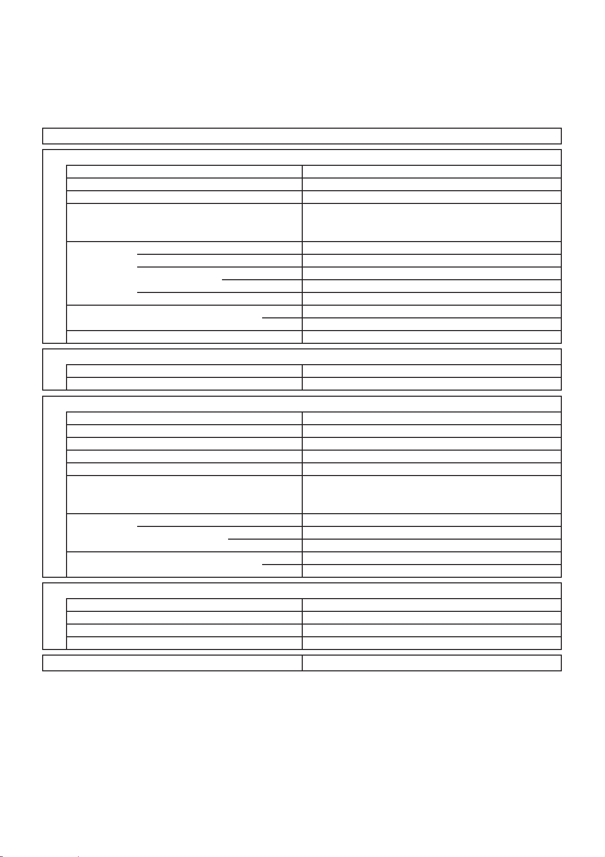
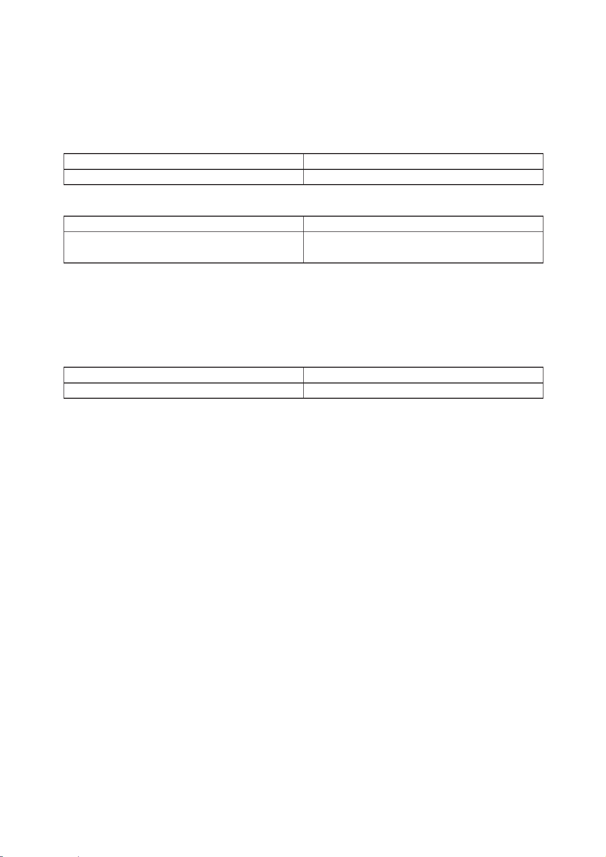
3. DIMENSIONAL DATA
16
Indoor Unit SAP-K77RAX
SAP-K97RAX
SAP-K127RAX
Outdoor Unit SAP-C77RAX
SAP-C97RAX
Unit: mm
06066
Wide tube service valve
dia.9.52(3/8")
Narrow tube service valve
dia.6.35(1/4")
446
14
78
24044264
296
482
11
372
ID:18
27 127
87 47
17
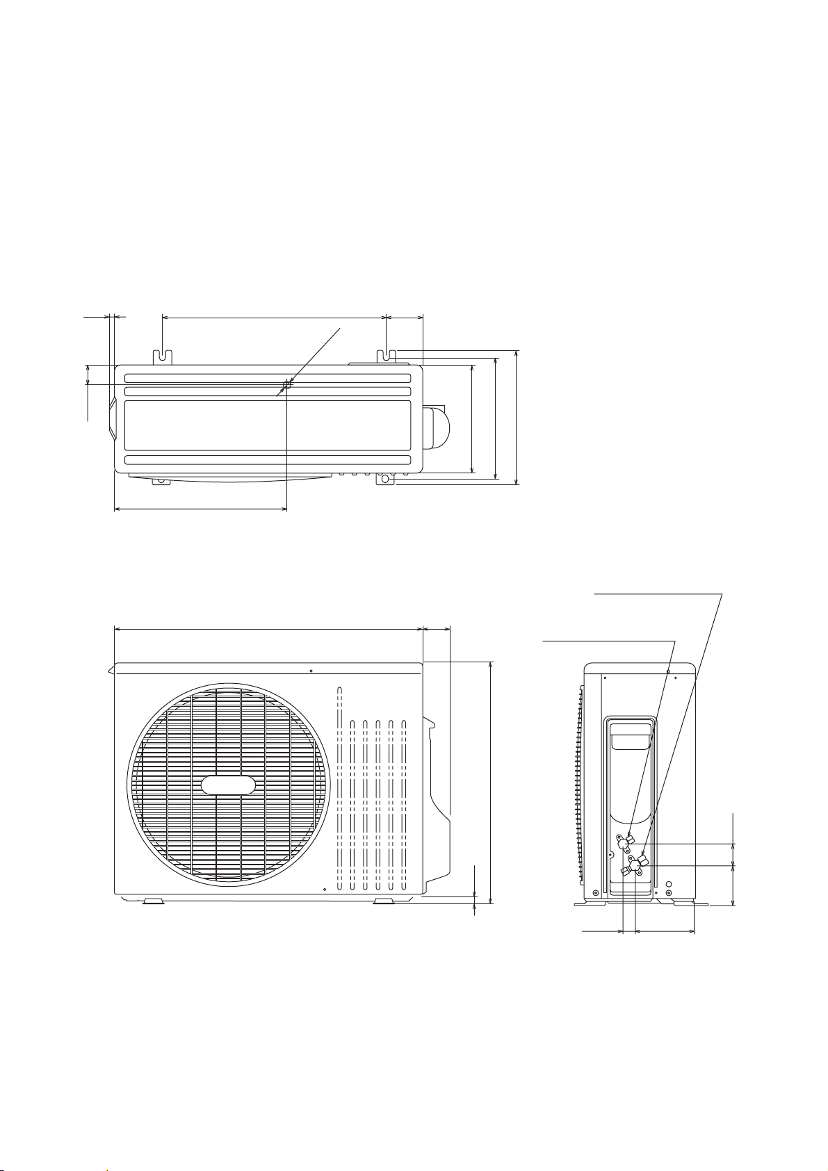
Outdoor Unit SAP-C127RAX
Unit: mm
06066
Wide tube service valve
dia.12.7(1/2")
Narrow tube service valve
dia.6.35(1/4")
510
14
78
24045264
296
48211
370
ID:18
27 127
87 47
18
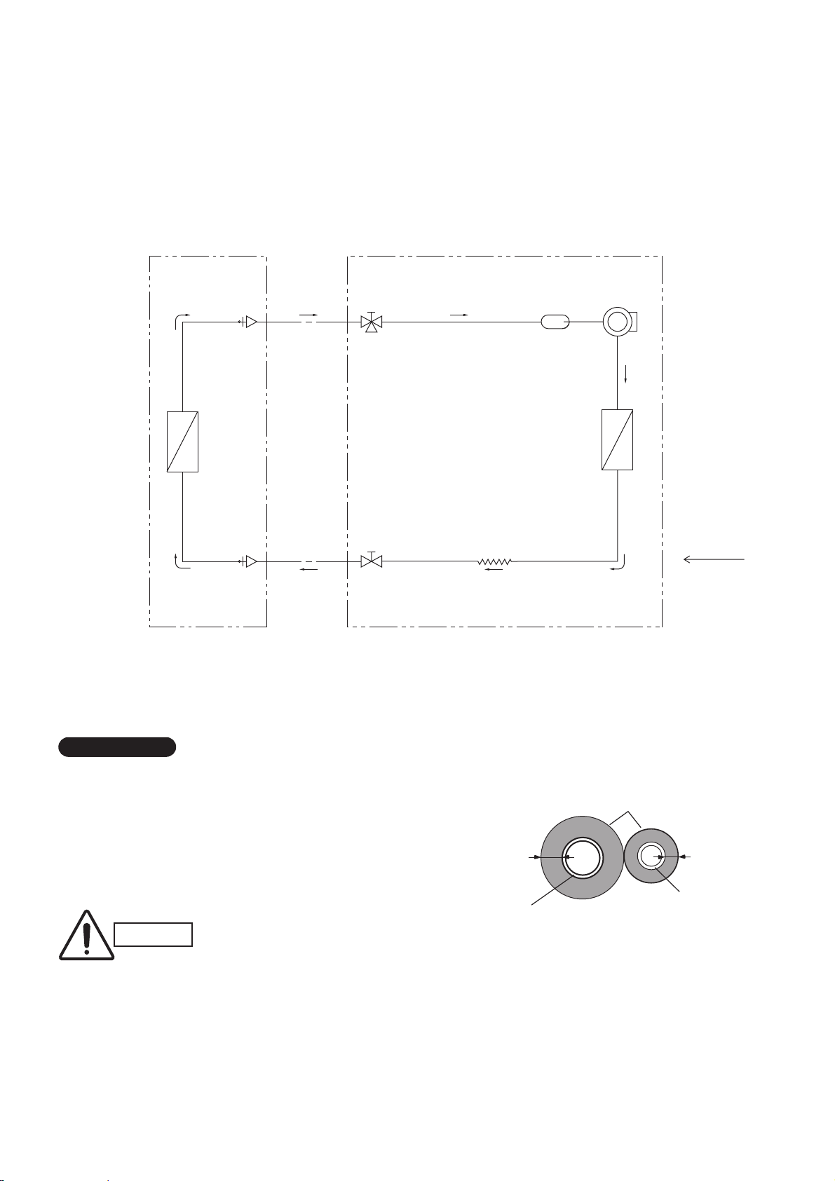
4. REFRIGERANT FLOW DIAGRAM
4-1. Refrigerant Flow Diagram
Indoor Unit SAP-K77RAX
SAP-K97RAX
SAP-K127RAX
Outdoor Unit SAP-C77RAX
SAP-C97RAX
SAP-C127RAX
Insulation of Refrigerant Tubing
Because capillary tubing is used in the outdoor unit, both the
wide and narrow tubes of this air conditioner become cold. To
prevent heat loss and wet floors due to dripping of
condensation, both tubes must be well insulated with a
proper insulation material. The thickness of the insulation
should be a min. 8 mm.
After a tube has been insulated,
never try to bend it into a narrow
curve because it can cause the tube
to break or crack.
Wide tube
Thickness:
Min. 8 mm
Insulation
Narrow tube
Thickness:
Min. 8 mm
IMPORTANT
CAUTION
Compressor
Accumulator
Wide tube
service
valve
Wide tube
*1
*1 O.D. 9.52 mm (3/8")
...
77, 97 class
O.D. 12.7 mm (1/2")
...
127 class
Narrow
tube
service
valve
Narrow tube
O.D.
6.35 mm
(1/4")
Heat exchanger
Heat exchanger
Cooling cycle
tinu roodtuOtinu roodnI
Capillary tube
19
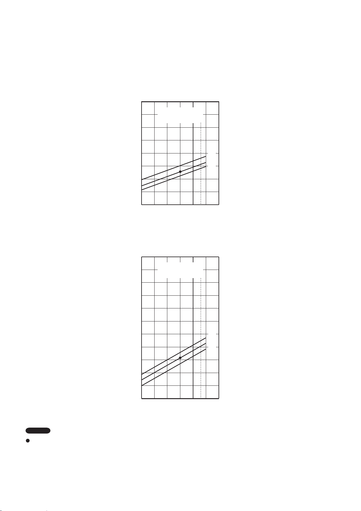
5. PERFORMANCE DATA
5-1. Performance charts
Indoor Unit SAP-K77RAX
Outdoor Unit SAP-C77RAX
Indoor air temperature 27 °C D.B. / 19 °C W.B.
Outdoor air temperature 35 °C D.B. / 24 °C W.B.
:Points of rating condition
Black dots in above charts indicate the following rating conditions.
NOTE
Cooling:
Indoor inlet air
D.B. temp. (°C)
9
8
7
6
5
4
3
2
1
25 30 35 40 45 50
Outdoor inlet air D.B. temp. (°C)
Operating current (A)
32
27
21
Indoor inlet air
D.B. temp. (°C)
Outdoor inlet air D.B. temp. (°C)
25 30 35 40 45 50
Low pressure at wide tube serveice valve MPaG
1.38
1.28
1.18
1.08
0.98
0.89
0.79
0.69
0.59
0.49
0.39
1.47
< Cooling Characteristics >
32
27
21
20

Indoor Unit SAP-K97RAX
Outdoor Unit SAP-C97RAX
Indoor inlet air
D.B. temp. (°C)
9
8
7
6
5
4
3
2
1
25 30 35 40 45 50
Outdoor inlet air D.B. temp. (°C)
Operating current (A)
32
27
21
Indoor inlet air
D.B. temp. (°C)
Outdoor inlet air D.B. temp. (°C)
25 30 35 40 45 50
Low pressure at wide tube serveice valve MPaG
< Cooling Characteristics >
32
27
21
Indoor air temperature 27 °C D.B. / 19 °C W.B.
Outdoor air temperature 35 °C D.B. / 24 °C W.B.
:Points of rating condition
Black dots in above charts indicate the following rating conditions.
NOTE
Cooling:
1.38
1.28
1.18
1.08
0.98
0.89
0.79
0.69
0.59
0.49
0.39
1.47
21
 Loading...