

Sanyo SAP-K18AM,SAP-K18AMS,SAP-C18AM,SAP-C18AMS,SAP-K18AGH,SAP-C18AGH,SAP-KC18AGH Instruction Manual

INSTRUCTION MANUAL
FIRST MADE FOR SAP-KC18AM, KC18AGH
MATERIAL OR MODEL *PAPER-JO
DIMENSION OR MAKER WOODFREE 80gm
COLOR BLACK Print
EZIS4AETON
APPROVALS
N.Yamazaki
2009/Nov /26
CHECK
Tai C.S
2009/Nov /25
DESIGN
Tai C S
2009/Sep/08
ON.RSNOISIVERETADSLAVORPPA
DRAWN
REMARKS:
PART CODE
SAMS ONLY
85S-6-4181-002-00-0
PART NAME
EXPLANATORY BOOKLET
1
A
P.g 33, additional Flare Nut
Tai C.S
22 Dec 09
1
Pub. OI-85264181002000 © SANYO 2010
SANYO Electric Co., Ltd.
Save These Instructions!
INSTRUCTION MANUAL
Split System Air Conditioner
COOL / DRY MODEL
SAP-K18AM / AMS
HEAT PUMP MODEL
HA1-PHA21K-PAS
INDOOOR UNIT OUTDOOR UNIT
SAP-C18AM / AMS
SAP-K18AGH SAP-C18AGH
Contents
Alert Symbols
The following symbols used in this manual, alert you to
potentially dangerous conditions to users, service personnel
Thank you for choosing SANYO air conditioner, please read
this instruction manual carefully before operating the unit
and keep it carefully for consultation.
This symbol stands for the items should be forbidden.
This symbol stands for the items should be followed.
Page
Operation and Maintenance
1. Notices for operation .............................................................
2. Notices for user ................................................................
3. Names and functions of each part ....................................
4. Operation of wireless remote control unit ..........................
5. Clean and care .................................................................
6. Troubleshooting ................................................................
Installation Service
7. Notices for installation ...........................................................
8. Installation dimension diagram . ........................................
9. Install indoor unit ..............................................................
10. Install outdoor unit ...........................................................
12. Check after installation and Test operation ......................
Product Information
If you have problems or questions concerning your Air Conditioner,
you will need the following information. Model and serial numbers
are on the nameplate on the bottom of the cabinet.
Model No. _______________Serial No. _______________
______
Date of purchase _______________________________________
Dealer’s addres _______________________________________
Phone number_________________
4
7
16
18
21
23
24
28
35
6
2
or the appliance:
1
11. Pump down ....................................................................... 34
Instruction Manual
Instruction Manual
EG
1. NOTICES FOR OPERATION
2
The wrong repair will lead to an
electric shock or fire, so you
should contact the SANYO
service center for repair.
Select the most appropriate
temperature.
It can help to preclude the
electricity wasted.
Keep room
cooler than
outside about
5
C.
It can decrease the air
conditioning capacity.
Don't block the air intake or outlet
It can decrease the air conditioning
capacity or cause a malfunction.
Never use or store gasoline or
other flammable vapor or liquid
near the air conditioner.
It is very dangerous and it may
cause a fire or explosion.
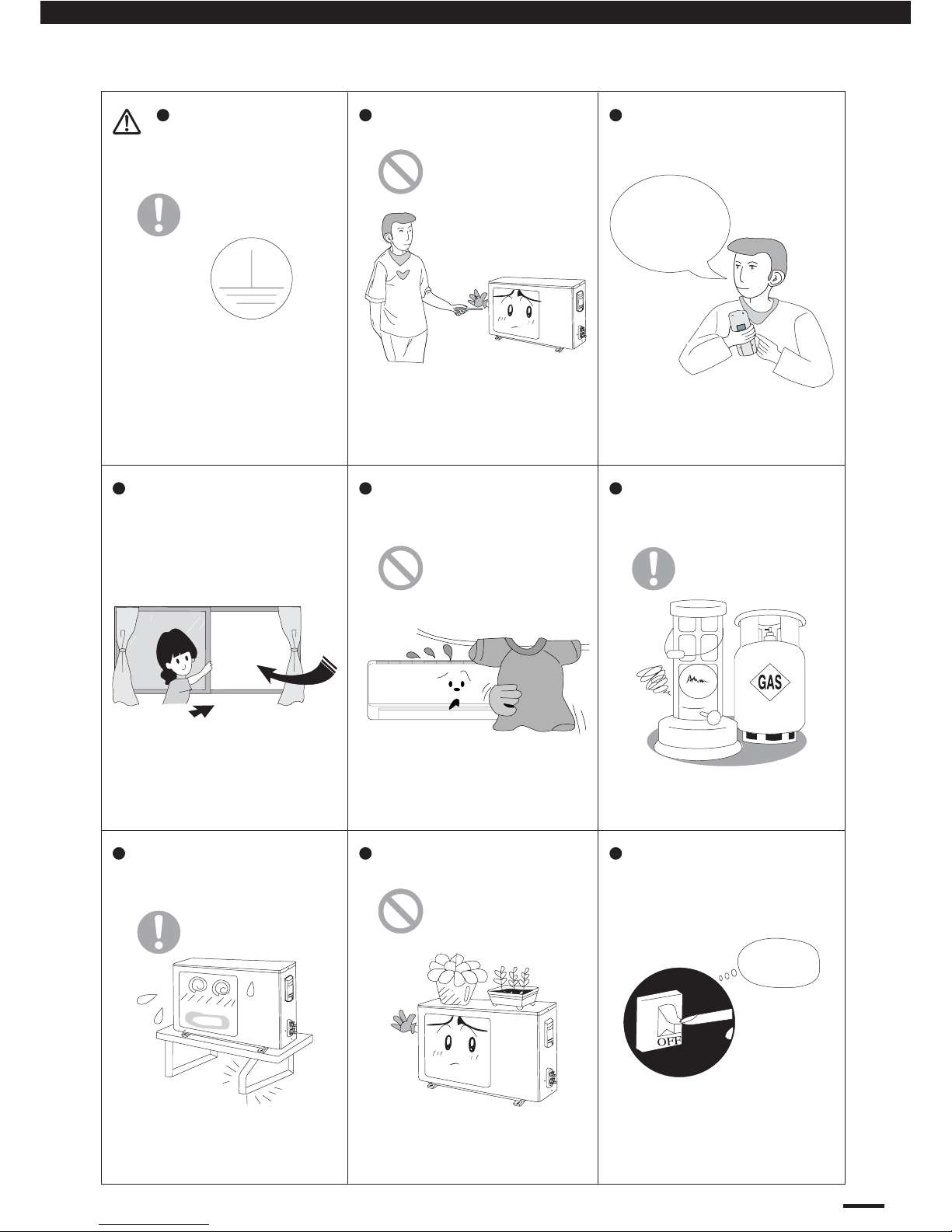
Please make sure whether
the installed stand is firm
enough or not.
If it is damaged, it may lead to
the fall of the unit and cause the
Do not step on the top of the
outdoor unit or place things on it.
As falling off the outdoor unit can
be dangerous.
Don't leave windows and doors
open for a long time while operating
the air conditioner.
If abnormal phenomenon (like
Cut Off
Power
If abnormal phenomenon
Don't attempt to repair the air
conditioner by yourself.
Each unit must be
properly grounded with a
ground (or earth) wire or
through the supply wiring.
If not, please ask the qualified
personnel to install.
Furthermore, do not connect
each wire to the gas pipe,water
pipe, drainage pipe or any other
improper places.
vents of both the outdoor and indoor
units.
injury.
burning odor, etc) occur, turn off
power supply and contact
SANYO service center.
Icontinues, the unit may be
damaged and cause electric
shock or fire.
o
Operation and Maintenance
3
1. NOTICES FOR OPERATION
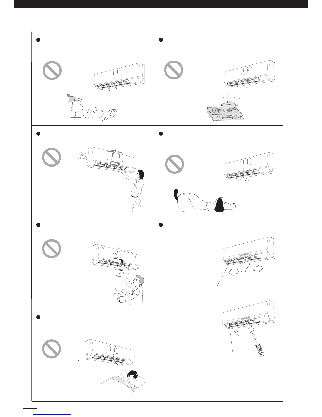
Do not blow the wind to animals and
plants directly. It can cause a bad
influence to them.
Adjusting the airflow direction correctly.
a) Horizontal:
The horizontal
airflow can be
adjusted by
moving the
louver with
your hand
to the left
or right.
b) Vertical:
The vetical air
flow can be
adjusted by
moving the flap
with the remote
control unit.
Use the SWING
button to set
either the auto
sweep or set to the
recommended position.
Louver of left /
right direction.
Flap of upward /
downward position.
FAN
OPER
SWING
AM
C
ON
ON/OFF
F
A
N
T
E
MP
-
T
EM
P
+
MOD
E
TI
ME
-
CA
NCE
L
T
I
ME
+
SWIN
G
S
L
E
E
P
T
-
O
N
T
-
O
F
F
C
L
O
C
K
Do not use the air conditioner for other
purposes,such as drying clothes,
preserving foods, etc.
Do not place a space heater near the air
conditioner. CO toxicosis may occur as
a result of imcomplete burning.
Do not insert your hands or stick into
the air intake or outlet vents.
Splashing water on the air conditioner
can cause electric shock or malfunction.
Do not apply the cold wind to the body
for a long time. It can cause the health
problems.
Operation and Maintenance

EG
2. NOTICES FOR USER
4
Principle:
Air conditioner absorbs heat in the room and transmit to
outdoor and discharged, so that indoor ambient temperature
decreased. It's cooling capacity will decrease by the increase
of outdoor ambient temperature.
Anti-freezing Function:
If the units is running in COOL mode and in low temperature,
there will be frost formed on the heat exchanger, when
indoor heat exchanger temperature decreased below 0 C,
the indoor unit micro-computer will stop compressor running
and protect the unit.
Principle:
1. Air conditioner absorbs heat from the outdoor and transmit
to indoor and evaporated, so that indoor temperature
increased. Its heating capacity will decrease by the
decrease of outdoor ambient temperature.
2. If outdoor temperature got lower, please operate with
other heating ventilating equipments.
Defrosting:
1. When outdoor temperature is low but high humidity, after a
long while running, frost will form on outdoor unit, that will
effect the heating effect. At this time, the auto defrosting
function will act, and the heat running will stop for 8-10
minutes.
2. During the auto defrosting function, both the fan motors of
indoor unit and outdoor unit will stop operate.
3. During the defrosting function, the indoor indicator flashes
and the outdoor unit may emit vapor. This is due to the
defrosting, it is not malfunction.
4. After defrosting finished, the heating will recover
automatically.
Cold Draft Prevention:
In "HEAT" mode, the indoor blower will no act at the
following 3 status, while the heat exchanger haven't achieve
the certain temperature. This is to prevent cool air blowing.
(Within 2 minutes).
1. Heating starts.
2. After auto defrosting finished.
3. Heating under low ambient temperature.
Gentle Breeze
In the following situation, the indoor unit may blow gentle
breeze, and the guide louver rotate to a certain position:
1. In “Heat” mode, the unit turned on, the compressor does
not arrive the starting condition
2. In “Heat” mode, the temperature arrive at the setting
value and the compressor stop running about 1min.
2.1 Working Principle
and Special
Functions for
Cooling
2.2 Working Principle
and Special
Functions for
Heating
(Heat Pump
Model Only)
o
Operation and Maintenance
5
2. NOTICES FOR USER
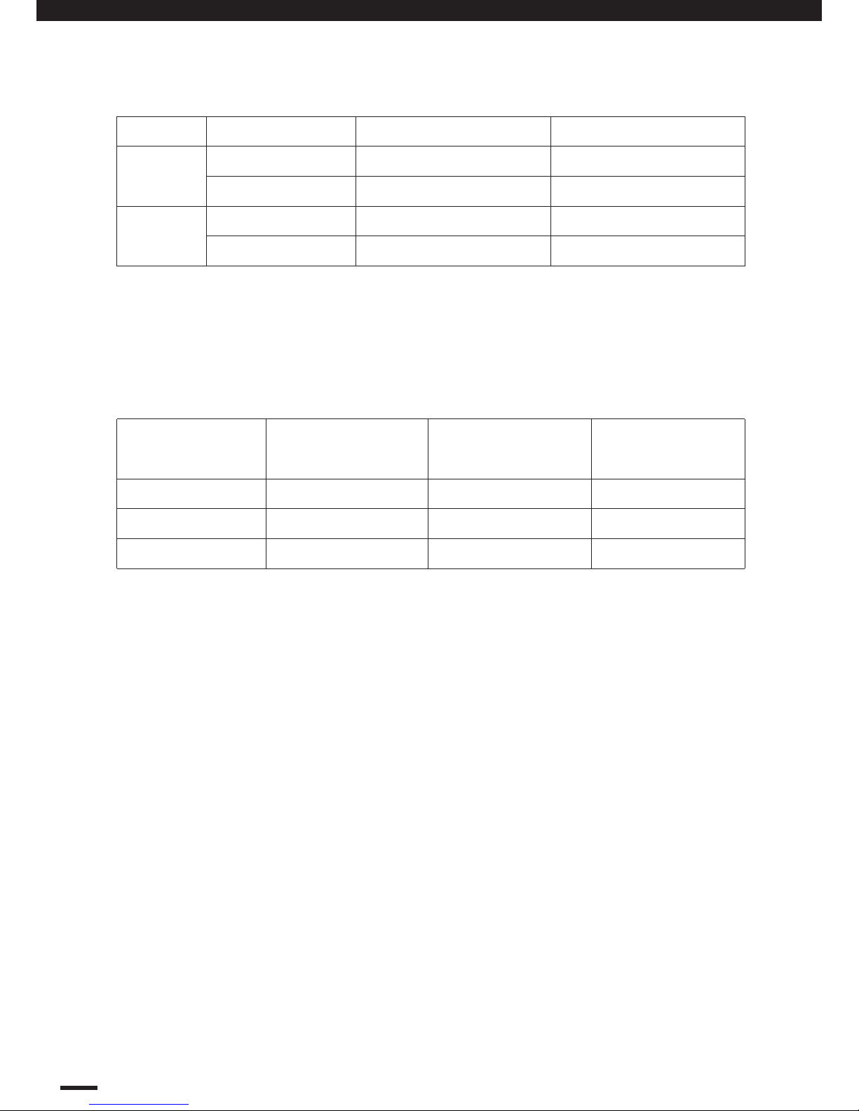
2.3 Working Temperature Range
2.4 The Conditions of Unit Can't Operate Normally.
In the following temp. range, the protection device may act, this may cause unit stop
running.
The operating temperature range (outdoor temperature) for cooling unit is 21 °C ~ 43 °C;
for cooling and heating unit is -5 °C ~ 43 °C.
Under the relative humidity is above 80% ( doors and windows are opened) when cooling
or dehumidifying for a long time, there may have dew drip off near the air vent.
COOLING
HEATING
Temperature Indoor air temperature Outdoor air temperature
Max.
Min.
Max.
Min.
32 °C DB / 23 °C DB
21 °C DB / 15 °C DB
27 °C DB / ---
20 °C DB / ---
43 °C DB / 26 °C DB
21 °C DB / ---
24 °C DB / 18 °C DB
-5 °C DB / -6 °C DB
“COOL” running
“HEAT” running
“DRY” running
Outdoor temperature
above
Outdoor temperature
below
Indoor temperature
above
24°C
43°C
18°C
---
--- ---
Operation and Maintenance
-7°C
21°C
27°C
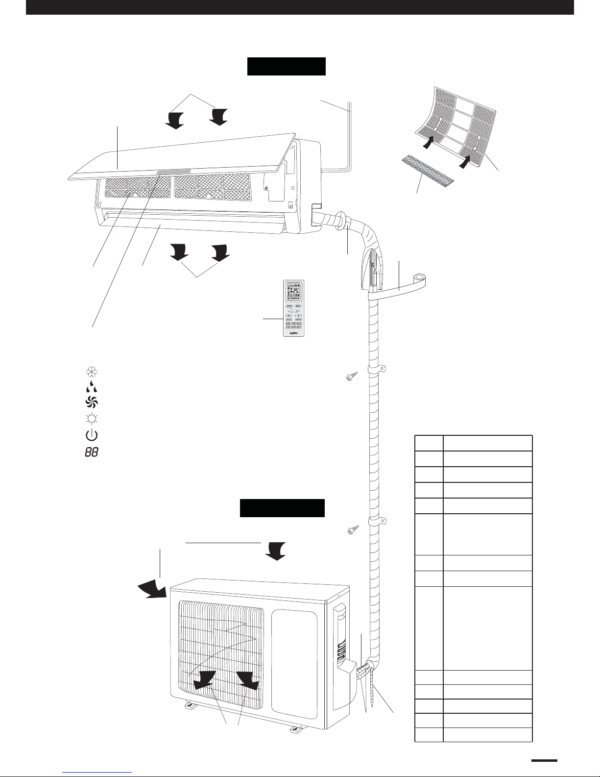
3. NAMES AND FUCTIONS OF EACH PART
6
Indoor Unit
Outdoor Unit
:Cool
:Dry
:Fan
:Heat
:Set temp.
:Run
The pattern in displayer:
*(5) x 2pcs
Back side
of part (4)
S/n
art Name
1
)
ower
cable
2
)
mot
e c
ontro
l
(3
)
ront Panel
4
)
t
er
5
)
Silver Ion Filter
6
)
uide Louver
7)Receiver
8
)
n
dica
tor
Cool
Dry
Fa
n
Heat
Ru
n
S
et Temp.
9
)
Wall Pipe
10
)nd T
ape
11
)
onnection Wir
e
Drainage Pipe
12
)
onnection Pip
e
13)
(6)
(11)
(12)
Air intake
Air outlet
Air inlet
Air outlet
(9)
(10)
(13)
(3)
(1)
(4)
Wireless
remote control
(2)
(7) (8)
Operation and Maintenance
*Only for
SAP-K18AMS
7
4. OPERATION OF WIRELESS REMOTE CONTROL UNIT
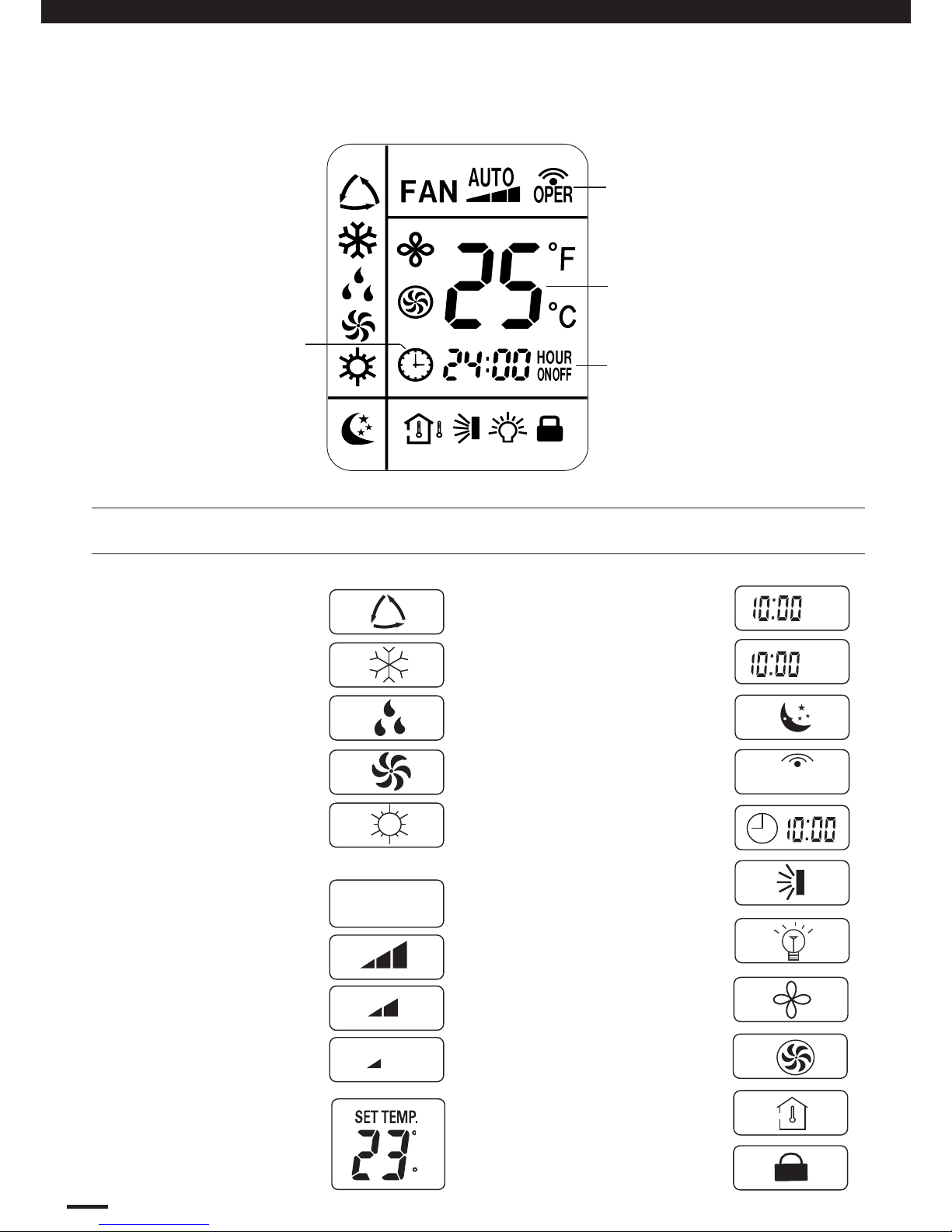
4.1 Remote Control Unit (Display)
Displayed when
transmitting data
(1) Operation mode
COOL ..........................
DRY.......... ....................
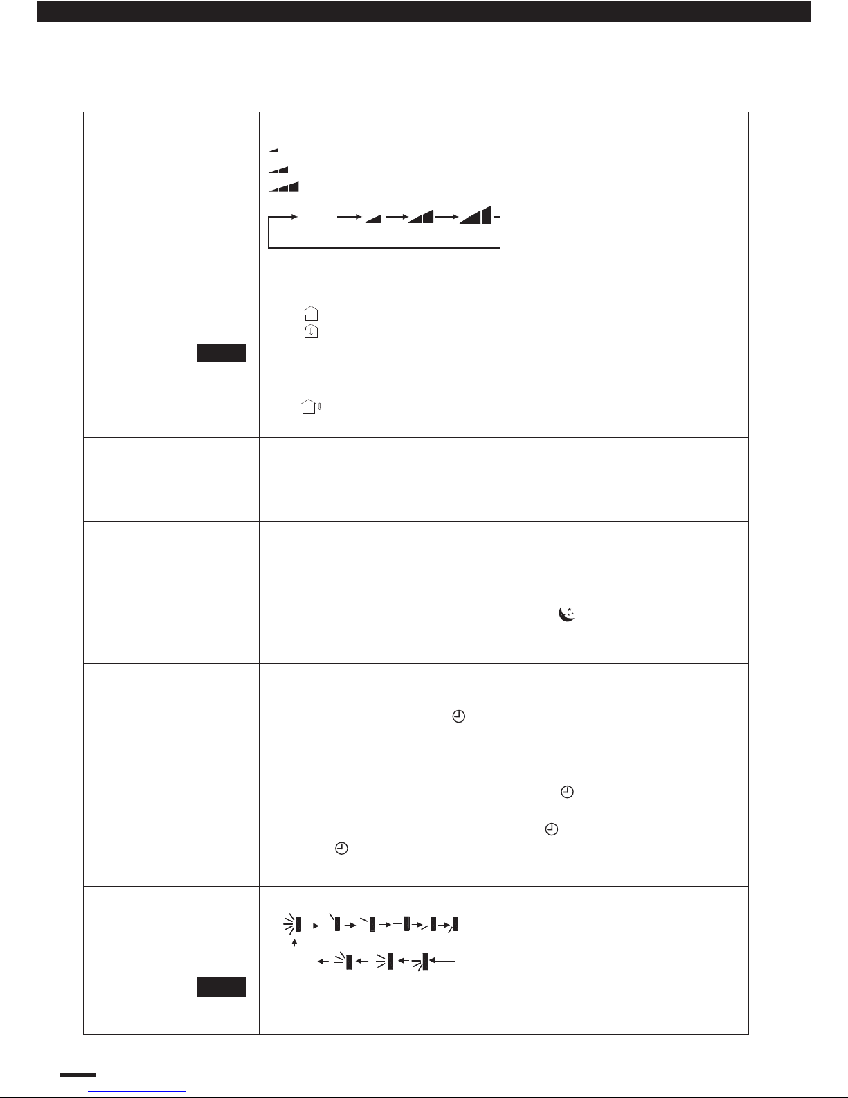
(2) Fan speed
Automatic operation .....
HIGH ............................
MID...............................
LOW ............................
(3) Set temperature
16 – 30 °C
When set to 23 °C ...
Symbols
(4) Timer
24-hour ON Timer .........
24hour OFF Timer .........
(5) Sleep ..............................
(6) Confirmation of ..............
transmission
(7) Clock indication ............
(8) Sweep indication ............
Displayed when setting
temperature
Displayed when setting
timer
Displayed the clock
AUTO
FAN .............................
HEAT ............................
AUTO ..........................
(Heat Pump model Only)
(9) Light .............................
(10) Blow .............................
(11) Turbo ...........................
F
C
ON
OFF
(12) TEMP ...........................
OPER
(13) Lock ............................
Operation and Maintenance
EG
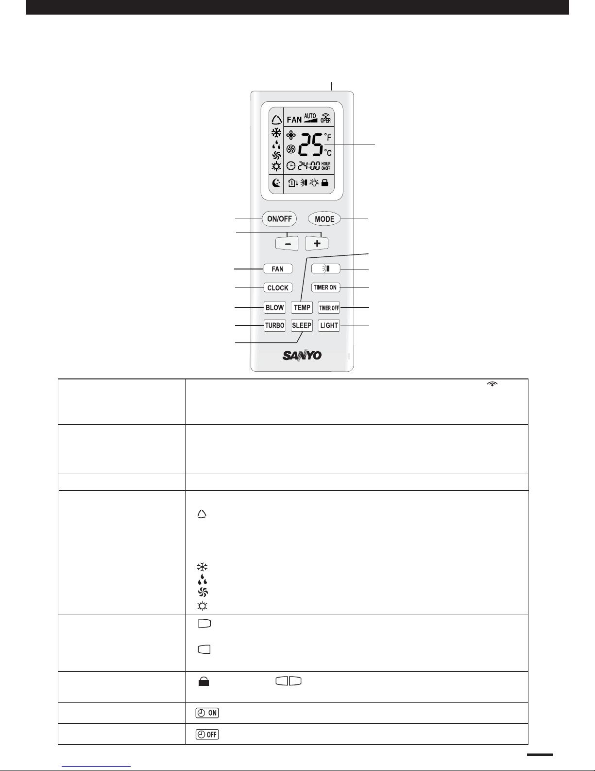
4. OPERATION OF WIRELESS REMOTE CONTROL UNIT
8
When you press the buttons on the remote control unit, the
mark appears in the display to transmit the setting changes to
the receiver in the air conditioner.
Information on the operating conditions is displayed while the
remote control unit is switched on. If the unit is turned off, only
CLOCK and TEMP was displayed.
: Press the (+) button to increase set temperature, continue
press 2 seconds for fast increasing set temperature.
: Press the (-) button to reduce set temperature, continue
press 2 seconds for fast reducing set temperature.
This button is for turning the air conditioner ON and OFF.
Transmitter
Display
(+) / (-) setting
buttons
ON/OFF operation
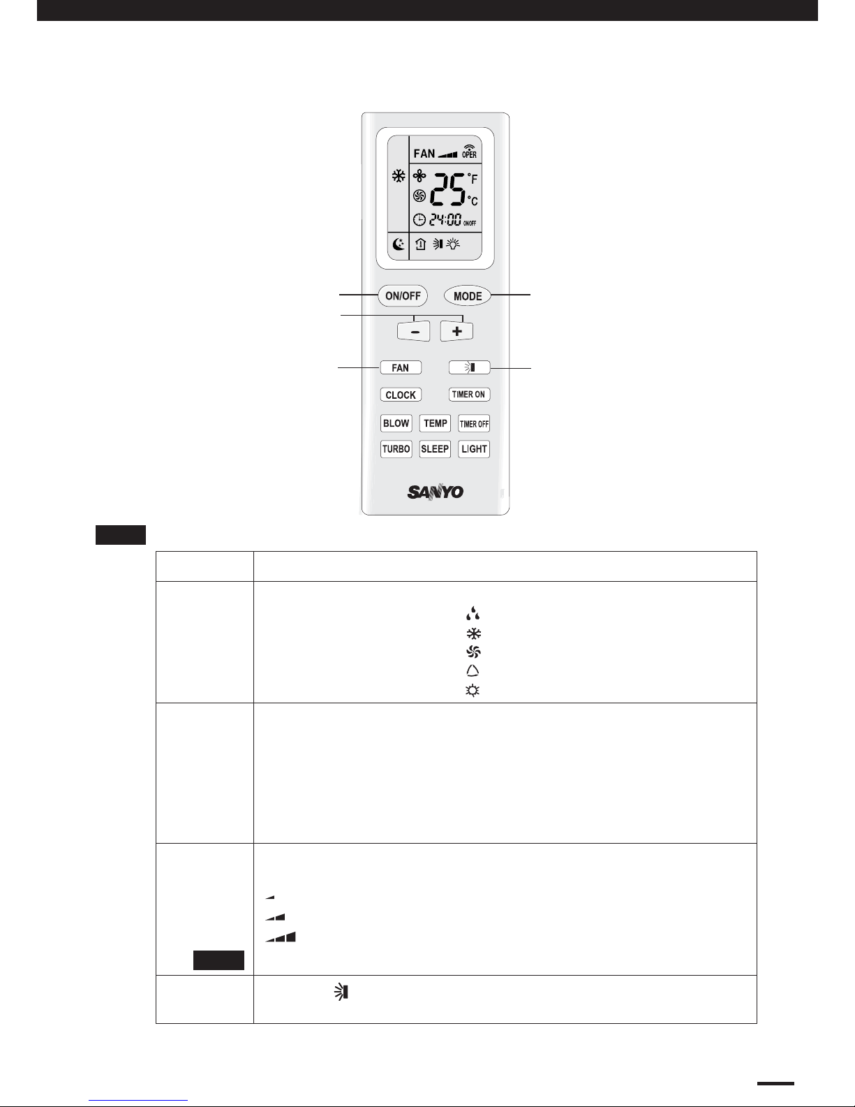
4.2 Remote Control Unit (Functions)
Display
TEMP. setting button
ON/OFF operation button
TIMER ON button
TIMER OFF button
Signal Transmitter
MODE operation button
FAN SPEED Selector button
SLEEP button
CLOCK button
SWING button
: The air conditioner starts at the set time.
: The air conditioner stops at the set time.
To select “AUTO” “COOL”, “DRY” “FAN” or “HEAT” mode.
TIMER ON button
TIMER OFF button
MODE selector button
(DRY)
(COOL)
: When choosed this setting, the air conditioner calculates
thedifference between the thermostat setting and the room
temperature and automatically switches to the “COOL” or
“HEAT” mode as appropriate.
: The air conditioner makes the room cooler.
: The air conditioner reduces the humidity in the room.
: The air conditioner run the indoor fan only.
: The air conditioner makes the room warmer.
(AUTO)
(FAN)
(HEAT)
LOCK / UNLOCK
button
: Press the button at the same time to lock or unlock
wireless remote controller.
-
+
OPER
+
-
LIGHT button
TURBO button
BLOW button
TEMP button
Operation and Maintenance
9
Press to begin or stop indoor fan from blowing indoor components
to dry. This function applicable to “COOL” & “DRY” mode only. In
“AUTO”, “FAN” as well as “HEAT” mode, “BLOW” function can not
be set up and there is no “BLOW” displaying.
Press this button will turn ON / OFF the display of indicator light.
TEMP button
BLOW button
SLEEP button
LIGHT button
Press to quickly cool or heat the room with intense cool or hot air.
TURBO button
CLOCK Button
SWING Button
For details, see “SLEEP MODE” (P.g 12). When you press this
button in the“DRY” or “COOL” mode, the mark appears in the
display, and the remote control unit will automatically adjust the set
temperature to save energy.
Press to see set temperature or indoor temperature which show on
the indicator lamp according to customer requirement.
: Display the presetting temperature.
: Display the indoor ambient temperature (5 seconds)
: Current displaying status will not be changed.
No Icon : Default to display the pesetting temperature.
To set the air swing direction which circurlarly change as:
OFF
When the guide louver start to swing up and down, if turn off
the Swing, the air guide louver will stop at the current
position. (refer P.g 14 for more detail)
Use this button to set the clock.
How it Works?
Press clock button, signal blink and display. Within 5 seconds,
the value can be adjusted by pressing “+” or “-” button, if press this
button continuously for 2 seconds and above, in every 0.5 seconds,
the value on ten place of Minute will be increased 1. During
blinking, repress the Clock button, signal will be constantly
displayed and it denotes the setting succeeded. After powered on,
12:00 is defaulted to display and signal will be displayed. If there
is signal be displayed that denotes the current time value is
Clock value, otherwise it is a Timer value.
4.2 Remote Control Unit Functions (Continued)
AUTO
: The air conditioner automatically decides the fan speeds.
: Low fan speed.
: Medium fan speed.
: High fan speed.
FAN SPEED selector
button
NOTE
It will display the ambient temperature for 5 seconds,
After 5s later, then will back to display the presetting
temperature.
NOTE
4. OPERATION OF WIRELESS REMOTE CONTROL UNIT
Operation and Maintenance
AUTO
10
4.3 Using the General Operation
Press the setting buttons as described below and change the settings as desired.
To STOP the air conditioner, press the ON/OFF operation button again.
STEP 2
STEP 1
STEP 4
STEP 5
STEP 3
STEP 1
STEP 3
STEP 4
STEP 5
To start the air conditioner, press the ON/OFF operation button.
Press the TEMP. setting buttons to change the temperature setting
to the desired temperature.
Adjustable temperature range:
30 °C (86 °F) max.—16 °C (61 °F) min.
Under “AUTO” operation, the temperature can not be adjust.
Under “HEAT” operation, the initial value is 28 °C (82 °F);
Under other operation, the initial value is 25 °C (77 °F).
Set the FAN SPEED selector button to the setting you want.
Press the
automatically
button and set the air blow direction as desired or
.
AUTO
: Auto fan speed.
: High fan speed.
: Middle fan speed.
: Low fan speed.
Under Dry mode, the fan speed is automatically set to LOW.
STEP 2
Press the MODE selector button and select the desired mode.
For DRY operation
For COOLING operation
For FAN only operation
For AUTO operation
For HEATING operation
(Only for Heat Pump Model)
→
→
→
→
→
NOTE
NOTE
4. OPERATION OF WIRELESS REMOTE CONTROL UNIT
Operation and Maintenance
 Loading...