

Sanyo SAP-DMRV93GJ,SAP-DMRV123GJ,SAP-DMRV183GJ,SAP-DMRV243GJ Technical & Service Manual
TECHNICAL & SERVICE MANUAL
INDOOR UNIT: SAP-DMRV93GJ
SAP-DMRV123GJ
SAP-DMRV183GJ
SAP-DMRV243GJ
DC INVERTER MULTI-SYSTEM AIR CONDITIONER
SAP-DMRV93GJ
SAP–DMRV123GJ
SAP–DMRV183GJ
Destination: General area (50Hz)
Europe (50Hz)
Australia (50Hz)
General area (60Hz)
Indoor Model No. Product Code No.
SAP-DMRV93GJ-S 1 852 084 90
SAP-DMRV243GJ
REVISION NO. SM700542-01
SAP-DMRV123GJ-S 1 852 084 91
SAP-DMRV183GJ-S 1 852 084 92
SAP-DMRV243GJ-S 1 852 084 93
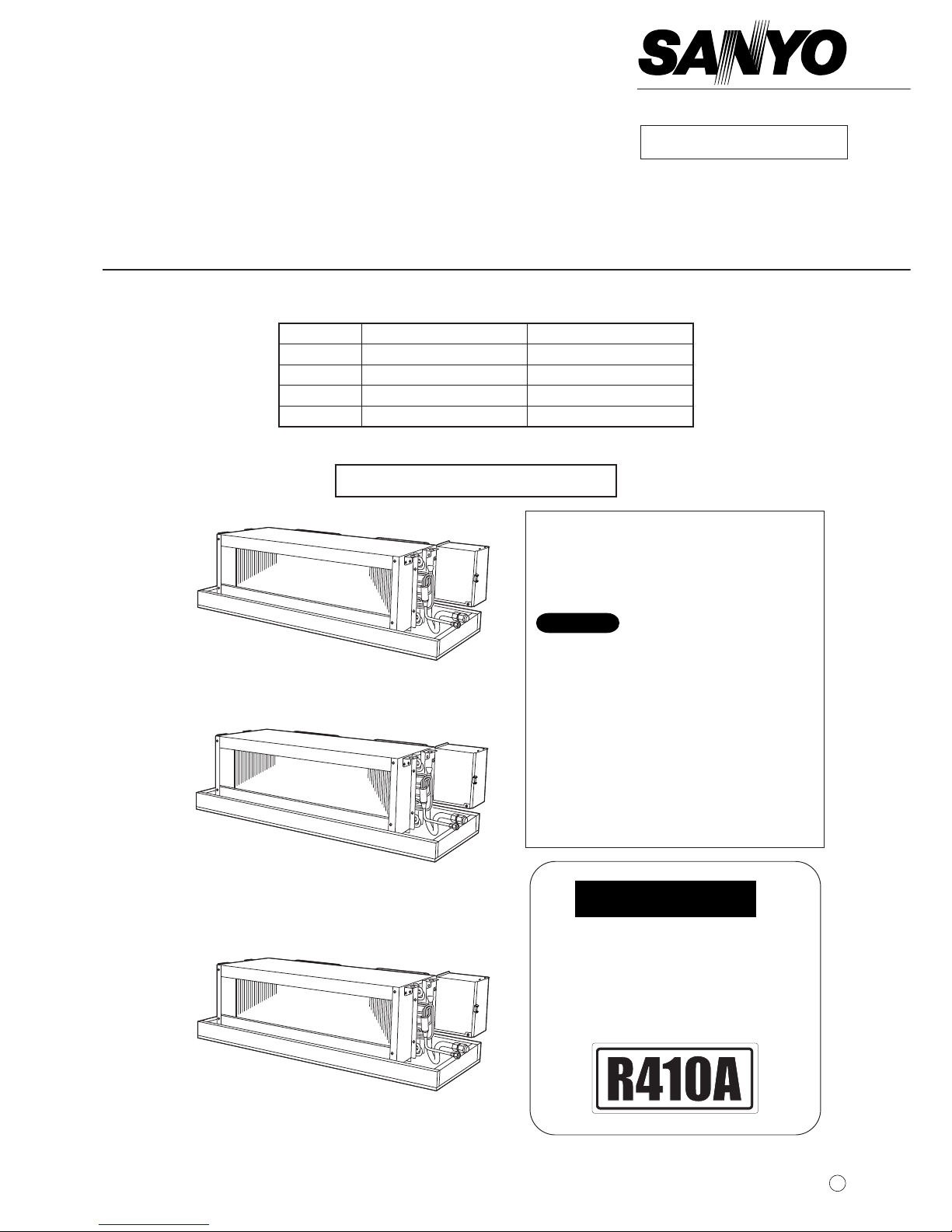
IMPORTANT
These air conditioners employ
new refrigerant R410A.
Pay special attention when
servicing the unit.
Concealed Duct Type Indoor Unit
< Combined Outdoor unit >
SAP-CMRV1923GJ (2-room multi unit)
SAP-CMRV2433GJ (3-room multi unit)
SAP-CMRV3143GJ (4-room multi unit)
1. The indoor unit SAP-DMRV243 can only be
combined with a 4-room multi unit. Therefore,
do not combine it with a 2-room multi unit or
3-room multi unit.
2. The indoor unit SAP-DMRV243 can operate
only in areas with 50Hz power source.
Therefore, do not use it in regions where the
source is 60Hz.
3. For details about the combinations, refer to
“Unit Combination Table” in the
T. Service
Manual
for the Multi Outdoor Units.
NOTE
Capacity
2.8 kW
3.6 kW
5.0 kW
7.0 kW
W
Revised Edition
NOV.2003
i
Important!
Please Read Before Starting
This air conditioning system meets strict safety and
operating standards. As the installer or service person,
it is an important part of your job to install or service the
system so it operates safely and efficiently.
For safe installation and trouble-free operation, you
must:
● Carefully read this instruction booklet before
beginning.
● Follow each installation or repair step exactly as
shown.
● Observe all local, state, and national electrical codes.
● Pay close attention to all warning and caution notices
given in this manual.
This symbol refers to a hazard or
unsafe practice which can result
in severe personal injury or
death.
This symbol refers to a hazard or
unsafe practice which can result
in personal injury or product or
property damage.
If Necessary, Get Help
These instructions are all you need for most installation
sites and maintenance conditions. If you require help
for a special problem, contact our sales/service outlet
or your certified dealer for additional instructions.
In Case of Improper Installation
The manufacturer shall in no way be responsible for
improper installation or maintenance service, including
failure to follow the instructions in this document.
Special Precautions
When Wiring
ELECTRICAL SHOCK CAN CAUSE
SEVERE PERSONAL INJURY OR
DEATH. ONLY A QUALIFIED,
EXPERIENCED ELECTRICIAN SHOULD
ATTEMPT TO WIRE THIS SYSTEM.
• Do not supply power to the unit until all wiring and
tubing are completed or reconnected and checked.
• Highly dangerous electrical voltages are used in this
system. Carefully refer to the wiring diagram and
these instructions when wiring. Improper connections
and inadequate grounding can cause accidental
injury or death.
• Ground the unit following local electrical codes.
• Connect all wiring tightly. Loose wiring may cause
overheating at connection points and a possible fire
hazard.
WARNING
CAUTION
WARNING
When Transporting
Be careful when picking up and moving the indoor and
outdoor units. Get a partner to help, and bend your
knees when lifting to reduce strain on your back. Sharp
edges or thin aluminum fins on the air conditioner can
cut your fingers.
When Installing…
…In a Ceiling or Wall
Make sure the ceiling/wall is strong enough to hold the
unit’s weight. It may be necessary to construct a strong
wood or metal frame to provide added support.
…In a Room
Properly insulate any tubing run inside a room to
prevent “sweating” that can cause dripping and water
damage to walls and floors.
…In Moist or Uneven Locations
Use a raised concrete pad or concrete blocks to
provide a solid, level foundation for the outdoor unit.
This prevents water damage and abnormal vibration.
…In an Area with High Winds
Securely anchor the outdoor unit down with bolts and a
metal frame. Provide a suitable air baffle.
…In a Snowy Area (for Heat Pump-type Systems)
Install the outdoor unit on a raised platform that is
higher than drifting snow. Provide snow vents.
When Connecting Refrigerant Tubing
• Use the flare method for connecting tubing.
• Apply refrigerant lubricant to the matching surfaces
of the flare and union tubes before connecting them,
then tighten the nut with a torque wrench for a leakfree connection.
• Check carefully for leaks before starting the test run.
When Servicing
• Turn the power off at the main power box (mains)
before opening the unit to check or repair electrical
parts and wiring.
• Keep your fingers and clothing away from any
moving parts.
• Clean up the site after you finish, remembering to
check that no metal scraps or bits of wiring have
been left inside the unit being serviced.
Others
• Ventilate any enclosed areas when installing or
testing the refrigeration system. Escaped refrigerant
gas, on contact with fire or heat, can produce
dangerously toxic gas.
• Confirm upon completing installation that no
refrigerant gas is leaking. If escaped gas comes in
contact with a stove, gas water heater, electric room
heater or other heat source, it can produce
dangerously toxic gas.
• Do not install only a single indoor unit.
CAUTION

Table of Contents
Page
1. OPERATING RANGE ............................................................................................................................... 1
2. SPECIFICATIONS
2-1. Unit Specifications.......................................................................................................................... 2
2-2. Major Component Specifications.................................................................................................... 6
2-3. Other Component Specifications.................................................................................................... 10
3. DIMENSIONAL DATA............................................................................................................................... 11
4. REFRIGERANT FLOW DIAGRAM .......................................................................................................... 12
5. DISASSEMBLY PROCEDURE FOR INDOOR UNIT
5-1. Removing Electrical Box................................................................................................................. 13
5-2. Removing Evaporator..................................................................................................................... 13
5-3. Removing Fan and Fan Motor........................................................................................................ 14
6. ELECTRICAL DATA
6-1. Electric Wiring Diagram.................................................................................................................. 17
7. INSTALLATION INSTRUCTIONS
7-1. Indoor Unit...................................................................................................................................... 18
7-2. Embedding the Tubing and Wiring................................................................................................. 21
7-3. Increasing the Fan Speed .............................................................................................................. 22
7-4. Mounting the Receiver.................................................................................................................... 24
7-5. Test Run......................................................................................................................................... 24
8. FUNCTIONS
8-1. Operation Functions....................................................................................................................... 25
8-2. Protective Functions....................................................................................................................... 27
9. TROUBLESHOOTING ............................................................................................................................. 28
.................................................................................................................................................. 32
APPENDIX
ii

1
1. OPERATING RANGE
Temperature Indoor Air Intake Temp. Outdoor Air Intake Temp.
Cooling
Maximum 32°C DB / 23°C W.B. 43°C D.B.
Minimum 19°C DB / 14°C W.B. 19°C D.B.
2
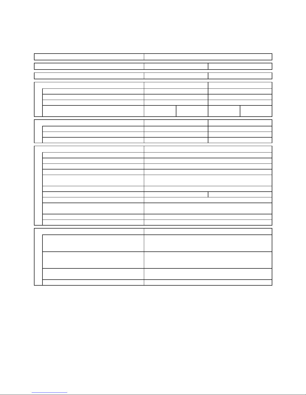
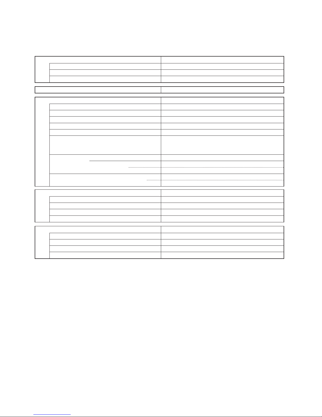
2. SPECIFICATIONS
2-1. Unit Specifications
Indoor Unit SAP–DMRV93GJ
Type Concealed duct type indoor unit
Power Source 220–240V ~ 50Hz 220V ~ 60Hz
Voltage rating 230 V 220 V
Performance Cooling Cooling
Capacity kW 2.8 ( 0.7 - 3.2 ) 2.8 ( 0.7 - 3.2 )
Air circulation (Hi / Me / Lo)
m3/h
850 / 760 / 700 850 / 760 / 700
Moisture removal (High) Liters/h 1.6 1.6
External
(Low) Pa 0 to 19.6 0 to 19.6 0 to 19.6 0 to 19.6
static pressure
(High) Pa 19.6 to 73.5 19.6 to 73.5 19.6 to 73.5 19.6 to 73.5
Electrical Rating Cooling Cooling
Available voltage range V 198 ~ 264 198 ~ 242
Running amperes A 0.41 0.40
Power input W 95 90
Features
Controls / Temperature control Microprocessor / I.C. thermostat
Control unit Wireless remote control unit
Timer ON/OFF 24 hours & Daily program,1-hour OFF
Fan speeds 3 and Auto
Airflow direction (Indoor) Horizontal —
Vertical —
Air filter Field supply
Operation sound Hi / Me / Lo dB-A 41 / 39 / 37 41 / 39 / 37
Refrigerant tubing connections Flare type
Refrigerant Narrow tube mm (in.) 6.35(1/4)
tube diameter Wide tube mm (in.) 9.52(3/8)
Refrigerant g R410A
Refrigerant tube kit Optional
Dimensions & Weight
Unit dimensions Height mm 260
Width mm 958
Depth mm 479
Package dimensions Height mm 374
Width mm 1,039
Depth mm 586
Weight Net kg 19
Shipping kg 25
Shipping volume
m
3
0.23
DATA SUBJECT TO CHANGE WITHOUT NOTICE.

3
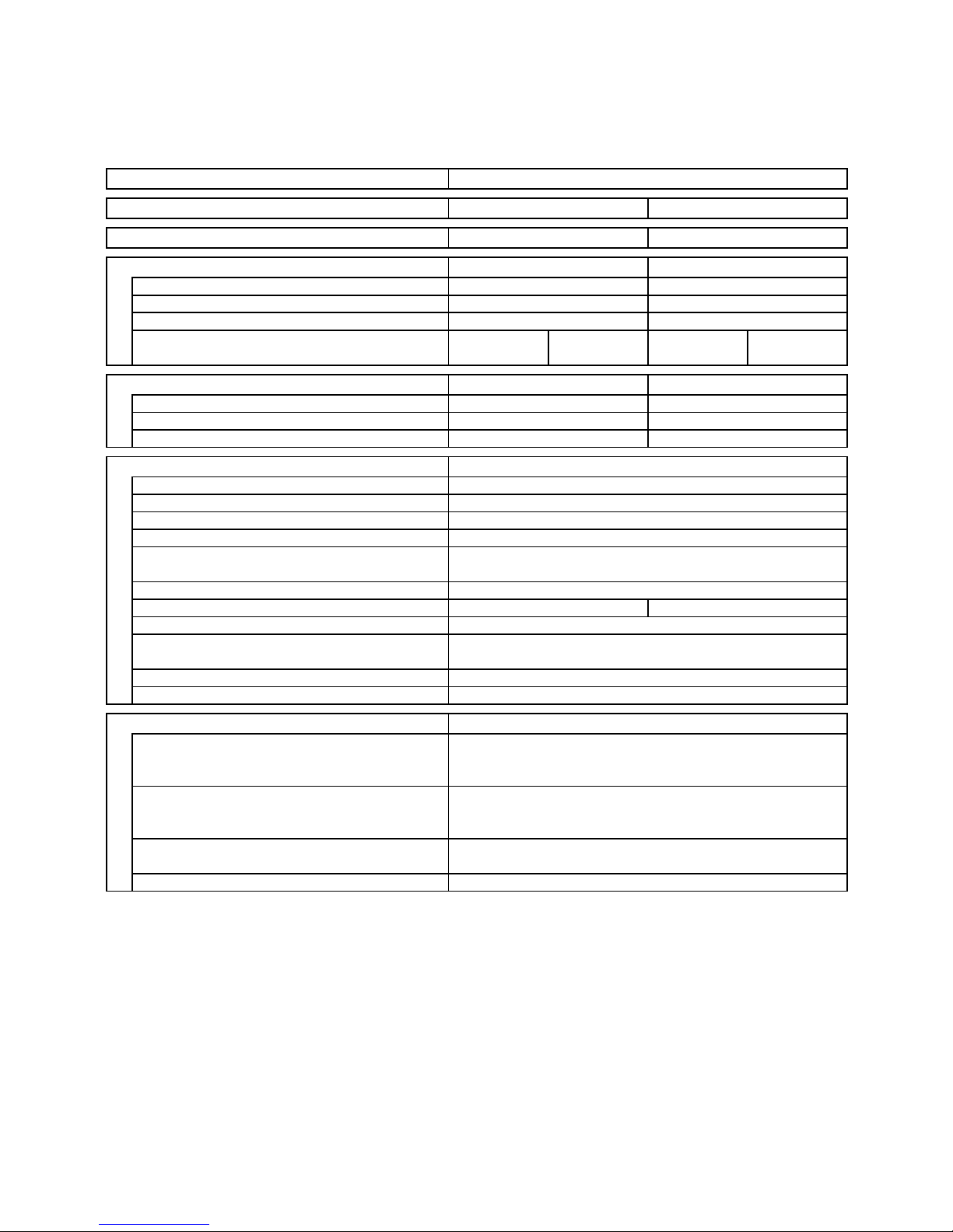
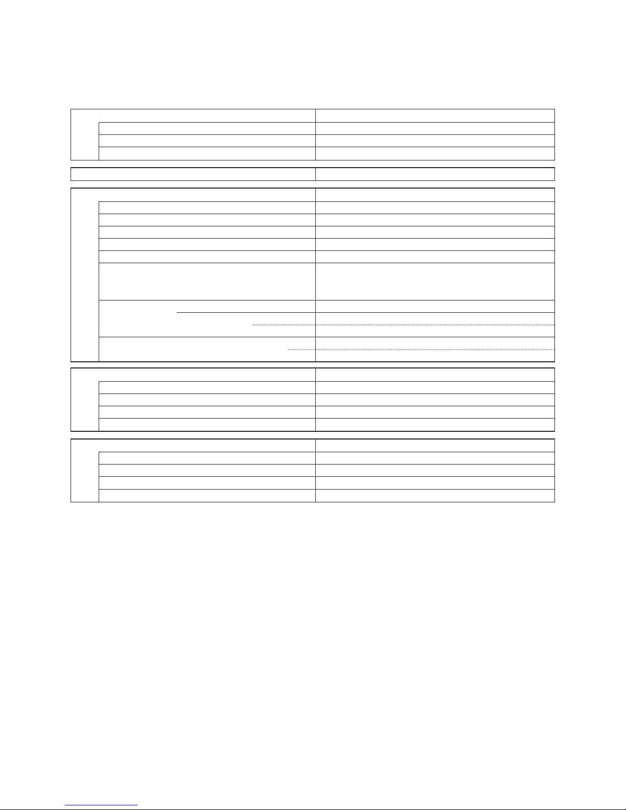
Indoor Unit SAP–DMRV123GJ
Type Concealed duct type indoor unit
Power Source 220–240V ~ 50Hz 220V ~ 60Hz
Voltage rating 230 V 220 V
Performance Cooling Cooling
Capacity kW 3.6 ( 0.8 - 3.6 ) 3.6 ( 0.8 - 3.6 )
Air circulation (Hi / Me / Lo)
m3/h
850 / 760 / 700 850 / 760 / 700
Moisture removal (High) Liters/h 2.0 2.0
External
(Low) Pa 0 to 19.6 0 to 19.6 0 to 19.6 0 to 19.6
static pressure
(High) Pa 19.6 to 73.5 19.6 to 73.5 19.6 to 73.5 19.6 to 73.5
Electrical Rating Cooling Cooling
Available voltage range V 198 ~ 264 198 ~ 242
Running amperes A 0.41 0.40
Power input W 95 90
Features
Controls / Temperature control Microprocessor / I.C. thermostat
Control unit Wireless remote control unit
Timer ON/OFF 24 hours & Daily program,1-hour OFF
Fan speeds 3 and Auto
Airflow direction (Indoor) Horizontal —
Vertical —
Air filter Field supply
Operation sound Hi / Me / Lo dB-A 41 / 39 / 37 41 / 39 / 37
Refrigerant tubing connections Flare type
Refrigerant Narrow tube mm (in.) 6.35(1/4)
tube diameter Wide tube mm (in.) 9.52(3/8)
Refrigerant g R410A
Refrigerant tube kit Optional
Dimensions & Weight
Unit dimensions Height mm 260
Width mm 958
Depth mm 479
Package dimensions Height mm 374
Width mm 1,039
Depth mm 586
Weight Net kg 19
Shipping kg 25
Shipping volume
m
3
0.23
DATA SUBJECT TO CHANGE WITHOUT NOTICE.

4
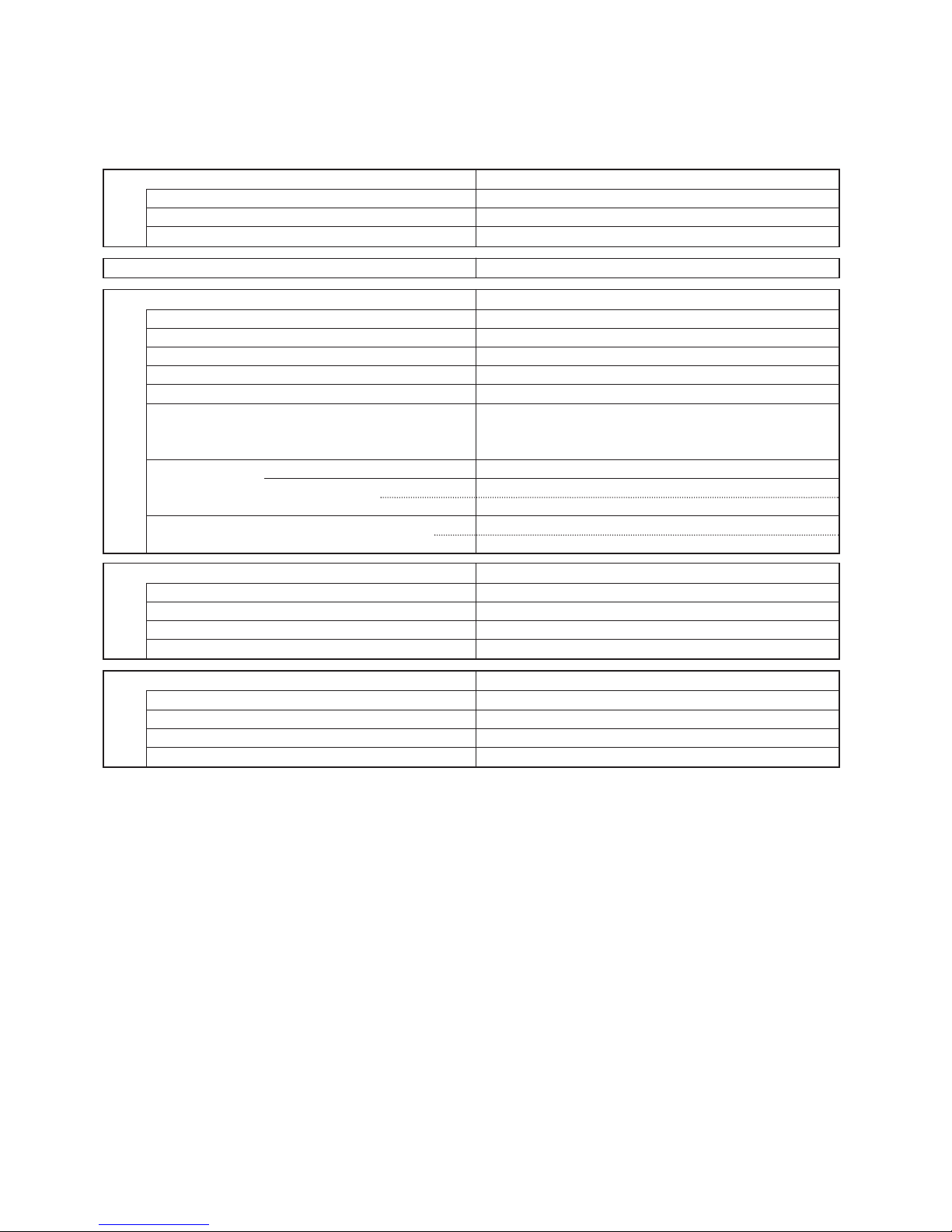
Indoor Unit SAP–DMRV183GJ
Type Concealed duct type indoor unit
Power Source 220–240V ~ 50Hz 220V ~ 60Hz
Voltage rating 230 V 220 V
Performance Cooling Cooling
Capacity kW 5.0 ( 1.1 - 5.8 ) 5.0 ( 1.1 - 5.8 )
Air circulation (Hi / Me / Lo)
m3/h
850 / 760 / 700 850 / 760 / 700
Moisture removal (High) Liters/h 2.8 2.8
External
(Low) Pa 0 to 19.6 0 to 19.6 0 to 19.6 0 to 19.6
static pressure
(High) Pa 19.6 to 73.5 19.6 to 73.5 19.6 to 73.5 19.6 to 73.5
Electrical Rating Cooling Cooling
Available voltage range V 198 ~ 264 198 ~ 242
Running amperes A 0.41 0.40
Power input W 95 90
Features
Controls / Temperature control Microprocessor / I.C. thermostat
Control unit Wireless remote control unit
Timer ON/OFF 24 hours & Daily program,1-hour OFF
Fan speeds 3 and Auto
Airflow direction (Indoor) Horizontal —
Vertical —
Air filter Field supply
Operation sound Hi / Me / Lo dB-A 41 / 39 / 37 41 / 39 / 37
Refrigerant tubing connections Flare type
Refrigerant Narrow tube mm (in.) 6.35(1/4)
tube diameter Wide tube mm (in.) 9.52(3/8)
Refrigerant g R410A
Refrigerant tube kit Optional
Dimensions & Weight
Unit dimensions Height mm 260
Width mm 958
Depth mm 479
Package dimensions Height mm 374
Width mm 1,039
Depth mm 586
Weight Net kg 19
Shipping kg 25
Shipping volume
m
3
0.23
DATA SUBJECT TO CHANGE WITHOUT NOTICE.
5
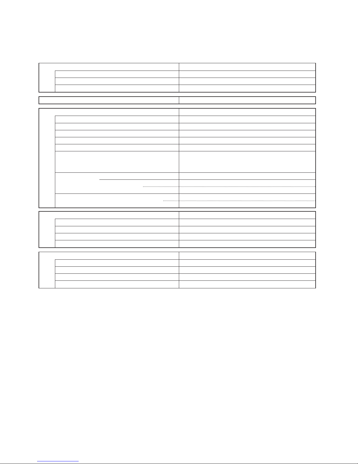
Indoor Unit SAP–DMRV243GJ
Type Concealed duct type indoor unit
Power Source 220–240V ~ 50Hz 220V ~ 60Hz
Voltage rating 230 V 220 V
Performance Cooling Cooling
Capacity kW 7.0 ( 1.5 - 8.1 ) —
Air circulation (Hi / Me / Lo)
m3/h
1,180 / 760 / 680 —
Moisture removal (High) Liters/h 3.4 —
External
(Low) Pa 0 to 19.6 0 to 19.6 — —
static pressure
(High) Pa 19.6 to 73.5 19.6 to 73.5 — —
Electrical Rating Cooling Cooling
Available voltage range V 198 ~ 264 —
Running amperes A 0.61 —
Power input W 138 —
Features
Controls / Temperature control Microprocessor / I.C. thermostat
Control unit Wireless remote control unit
Timer ON/OFF 24 hours & Daily program,1-hour OFF
Fan speeds 3 and Auto
Airflow direction (Indoor) Horizontal —
Vertical —
Air filter Field supply
Operation sound Hi / Me / Lo dB-A 52 / 41 / 39 —
Refrigerant tubing connections Flare type
Refrigerant Narrow tube mm (in.) 6.35(1/4)
tube diameter Wide tube mm (in.) 12.7(1/2)
Refrigerant g R410A
Refrigerant tube kit Optional
Dimensions & Weight
Unit dimensions Height mm 260
Width mm 958
Depth mm 479
Package dimensions Height mm 374
Width mm 1,039
Depth mm 586
Weight Net kg 19
Shipping kg 25
Shipping volume
m
3
0.23
DATA SUBJECT TO CHANGE WITHOUT NOTICE.
6
2-2. Major Component Specifications
2-2-1. Indoor Unit
Indoor Unit SAP–DMRV93GJ
DATA SUBJECT TO CHANGE WITHOUT NOTICE.
Control PCB
Part No. POW-DMRV243GJ
Controls Microprocessor
Control circuit fuse 2.50V 3.15A
Flap Motor and Louver Motor
Type —
Model —
Rating —
Coil resistance (Ambient temp. 25°C) Ω —
Heat Exchanger Coil
Coil Aluminum plate fin / Copper tube
Rows 2
Fin pitch mm 1.6
Face area m
2
0.118
Fan & Fan Motor
Type Centrifugal fan
Q’ty … Dia. and length mm 2 … ø144/L162
Fan motor model … Q’ty KFG4X-51G5P-S
No. of poles … rpm (230V, High) 4 … 1009
Nominal output W 50
Coil resistance (Ambient temp. 20°C) Ω BRN – WHT: 141.0 ORG – YEL: 12.8
WHT – VLT: 37.7 YEL – BLK: 58.2
VLT – ORG: 21.0 BLK – PNK: 33.3
Safety devices Type Thermal protector
Operating temp. Open °C 130 ± 8
Close Automatic reclosing
Run capacitor µF 3.0
VAC 440
Remote Control Unit RCS-3MVPS4E
7
Indoor Unit SAP–DMRV123GJ
DATA SUBJECT TO CHANGE WITHOUT NOTICE.
Control PCB
Part No. POW-DMRV243GJ
Controls Microprocessor
Control circuit fuse 2.50V 3.15A
Flap Motor and Louver Motor
Type —
Model —
Rating —
Coil resistance (Ambient temp. 25°C) Ω —
Heat Exchanger Coil
Coil Aluminum plate fin / Copper tube
Rows 2
Fin pitch mm 1.6
Face area m
2
0.147
Fan & Fan Motor
Type Centrifugal fan
Q’ty … Dia. and length mm 2 … ø144/L162
Fan motor model … Q’ty KFG4X-51G5P-S
No. of poles … rpm (230V, High) 4 … 1009
Nominal output W 50
Coil resistance (Ambient temp. 20°C) Ω BRN – WHT: 141.0 ORG – YEL: 12.8
WHT – VLT: 37.7 YEL – BLK: 58.2
VLT – ORG: 21.0 BLK – PNK: 33.3
Safety devices Type Thermal protector
Operating temp. Open °C 130 ± 8
Close Automatic reclosing
Run capacitor µF 3.0
VAC 440
Remote Control Unit RCS-3MVPS4E
8
Indoor Unit SAP–DMRV183GJ
DATA SUBJECT TO CHANGE WITHOUT NOTICE.
Control PCB
Part No. POW-DMRV243GJ
Controls Microprocessor
Control circuit fuse 2.50V 3.15A
Flap Motor and Louver Motor
Type —
Model —
Rating —
Coil resistance (Ambient temp. 25°C) Ω —
Heat Exchanger Coil
Coil Aluminum plate fin / Copper tube
Rows 2
Fin pitch mm 1.3
Face area m
2
0.147
Fan & Fan Motor
Type Centrifugal fan
Q’ty … Dia. and length mm 2 … ø144/L162
Fan motor model … Q’ty KFG4X-51G5P-S
No. of poles … rpm (230V, High) 4 … 1009
Nominal output W 50
Coil resistance (Ambient temp. 20°C) Ω BRN – WHT: 141.0 ORG – YEL: 12.8
WHT – VLT: 37.7 YEL – BLK: 58.2
VLT – ORG: 21.0 BLK – PNK: 33.3
Safety devices Type Thermal protector
Operating temp. Open °C 130 ± 8
Close Automatic reclosing
Run capacitor µF 3.0
VAC 440
Remote Control Unit RCS-3MVPS4E
9
Indoor Unit SAP–DMRV243GJ
DATA SUBJECT TO CHANGE WITHOUT NOTICE.
Control PCB
Part No. POW-DMRV243GJ
Controls Microprocessor
Control circuit fuse 2.50V 3.15A
Flap Motor and Louver Motor
Type —
Model —
Rating —
Coil resistance (Ambient temp. 25°C) Ω —
Heat Exchanger Coil
Coil Aluminum plate fin / Copper tube
Rows 3
Fin pitch mm 1.3
Face area m
2
0.147
Fan & Fan Motor
Type Centrifugal fan
Q’ty … Dia. and length mm 2 … ø144/L162
Fan motor model … Q’ty KFG4X-91A5P-S
No. of poles … rpm (230V, High) 4 … 1330
Nominal output W 90
Coil resistance (Ambient temp. 20°C) Ω BRN – WHT: 87.1 ORG – YEL: 32.3
WHT – VLT: 15.1 YEL – BLK: 143.8
VLT – ORG: 111.8 BLK – PNK: 103.6
Safety devices Type Thermal protector
Operating temp. Open °C 130 ± 8
Close Automatic reclosing
Run capacitor µF 3.5
VAC 440
Remote Control Unit RCS-3MVPS4E
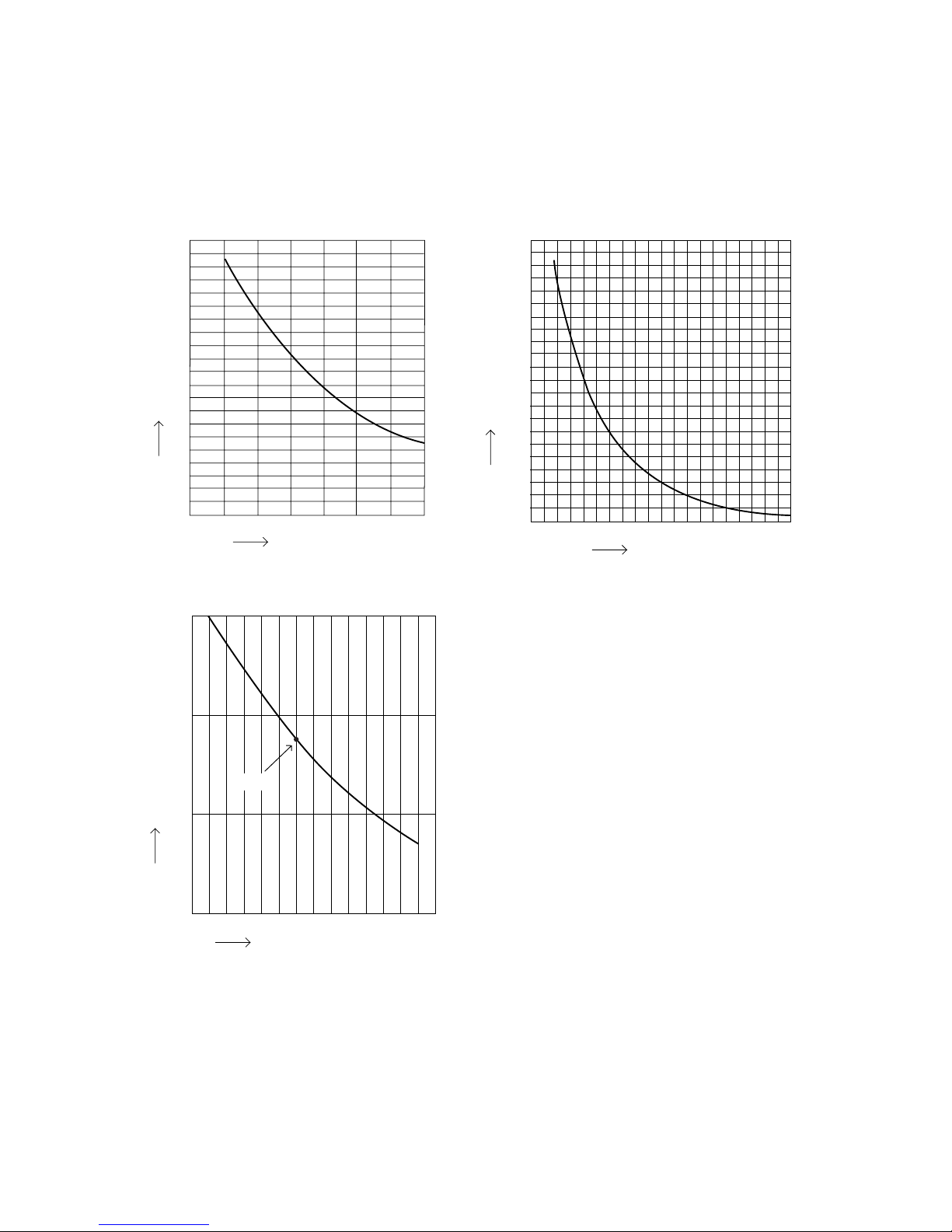
2-3. Other Component Specifications
10
Indoor Unit SAP–DMRV93GJ
SAP–DMRV123GJ
SAP–DMRV183GJ
SAP–DMRV243GJ
0
0 102030405060708090
40
60
80
100
120
140
160
180
200
20
10
1
2
3
4
5
6
7
8
9
10
15 20 25 30 35 40
• Indoor air temp sensor
• Indoor heat exchanger sensor
• Humidity sensor
30 35 40 45 50 55 60 65 70 75 80 85 90
1
10
100
1000
25°C
Resistance (Ω)
Resistance (Ω)
Resistance (Ω)
Temperature (°C)
Temperature (°C)
Relative humidity (%)
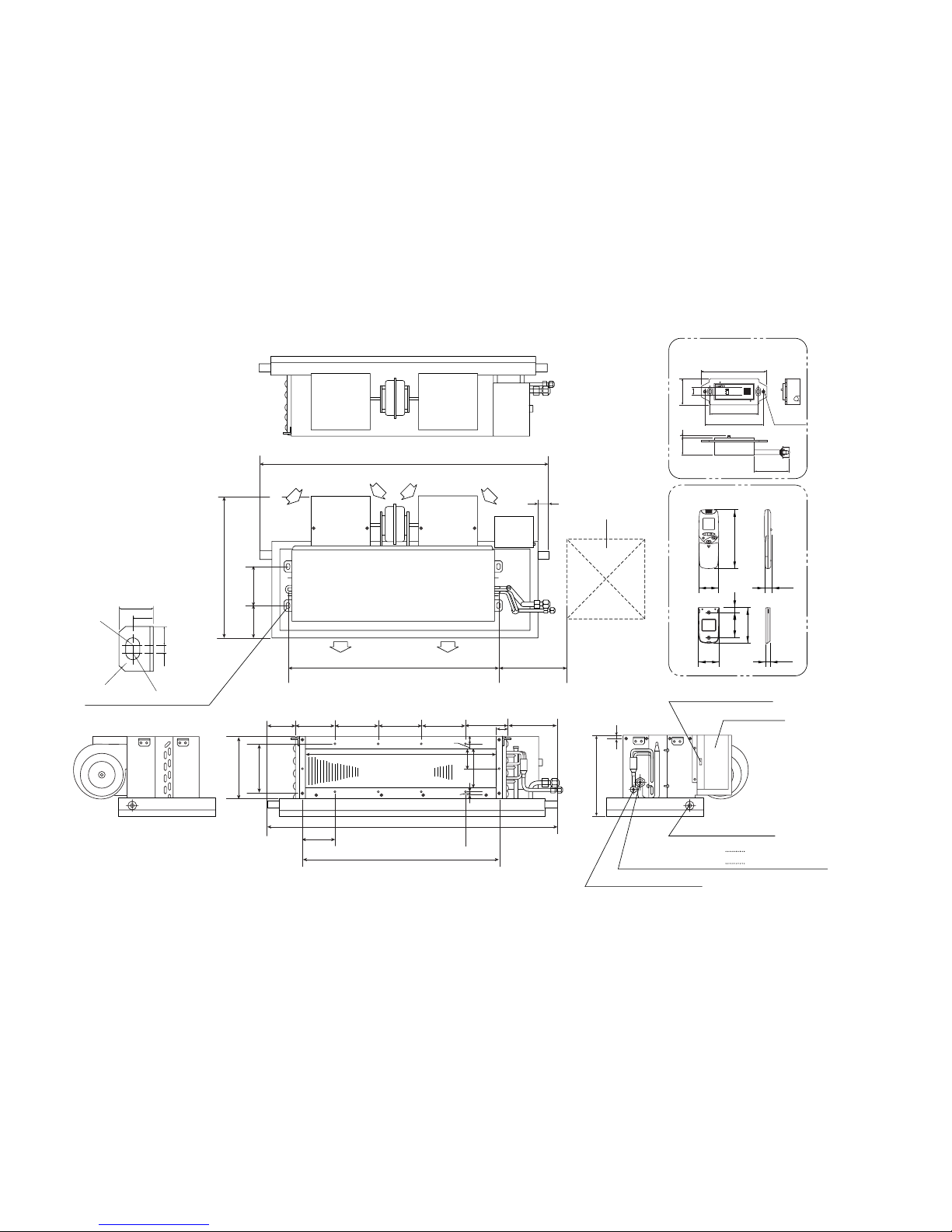
11
3. DIMENSIONAL DATA
Indoor Unit SAP–DMRV93GJ
SAP–DMRV123GJ
SAP–DMRV243GJ
SAP–DMRV183GJ
738
(Suspension bolt pitch)
(Suspension bolt pitch)
71
139 150 150 150 149 149
662
22
15
6.5
135
68
38
958
960
134
85
480
165
205
450 x 450
30
111
121
682
200
Inspection access
(Field work)
unit: mm
AIR DISCHARGE AIR DISCHARGE
AIR INTAKE
Narrow tube ø6.35 (1/4")
Drain pipe O.D. ø26.9
Wide tube ø9.52 (3/8")
DMRV93, 123, 183
Wide tube ø12.7 (1/2")
DMRV243
3.0
260
Connector for Reciever
Electrical box
16.5
7.0
30.0
18.0
R 6.5
C 5.0
R 6.5
4 – Hole for suspension bolt
AIR INTAKE
AIR INTAKE
Remote control unit
182
61 23
65
110
15
78
14.3
Remote control receiver
ON
OPERATION
TIMER
OFF
TEST
112
101
83.5
3700
2–
ø
3.5
4530.2 3
13
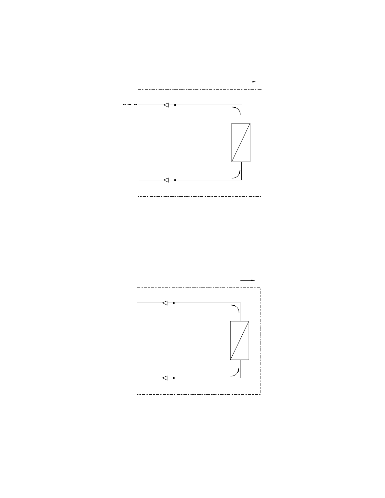
4. REFRIGERANT FLOW DIAGRAM
12
Indoor Unit SAP–DMRV93GJ
SAP–DMRV123GJ
SAP–DMRV183GJ
9.52
EC
P
6.35
Indoor unit
Cooling
Indoor heat
exchanger
12.7
EC
P
6.35
Indoor unit
Cooling
Indoor heat
exchanger
Indoor Unit SAP–DMRV243GJ
13
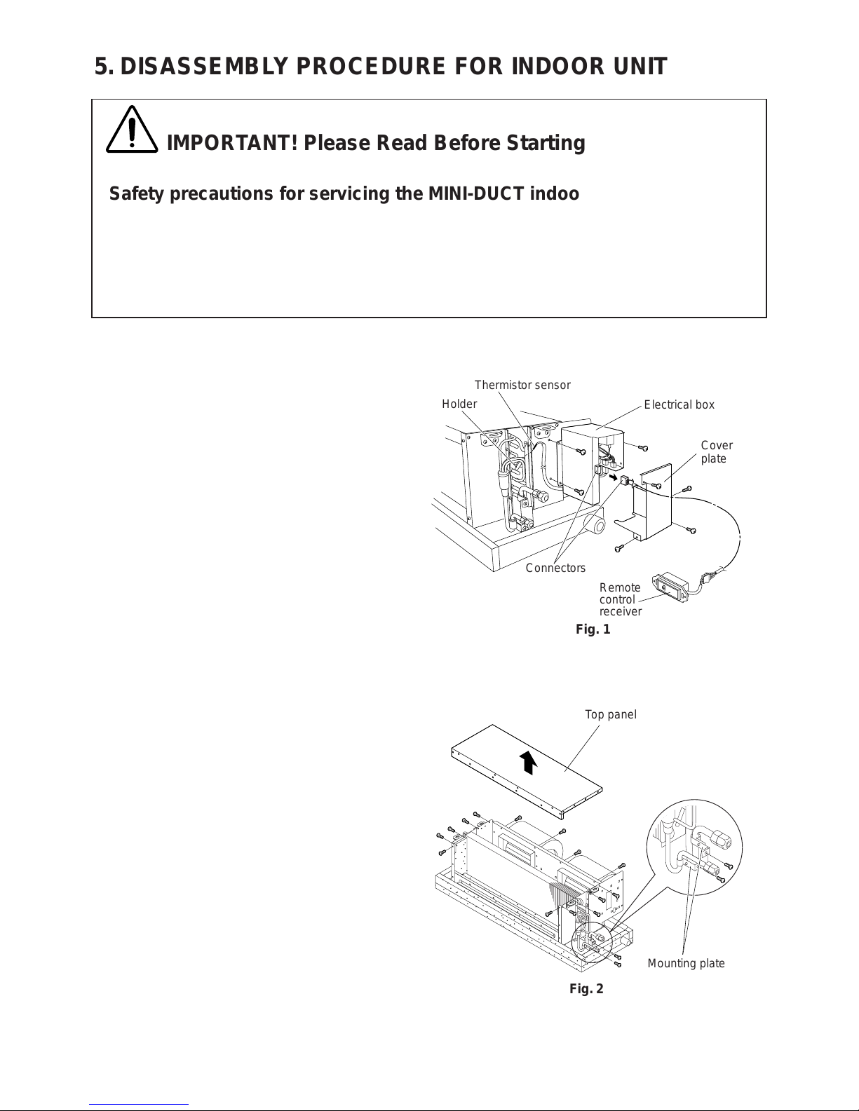
5-1. Removing Electrical Box
(1) Remove 4 screws used to attach the cover plate
of the electrical box. Then pull the plate toward
you. (Fig. 1)
(2) Pull the thermistor sensor from its holder. (Fig. 1)
(3) Remove 3 screws securing the electrical box
to the unit. (Fig. 1)
(4) Disconnect the connectors to disengage the
remote control receiver. (Fig. 1)
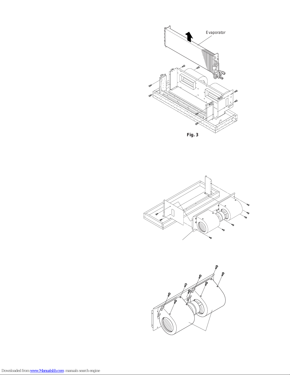
5-2. Removing Evaporator
(1) Remove 14 screws securing the top panel. (Fig. 2)
(2) Remove 2 screws holding the evaporator tubing
at the mounting plate. (Fig. 2)
,,
QQ
SS
,,
QQ
Top panel
Mounting plate
Fig. 2
Holder
Thermistor sensor
Electrical box
Cover
plate
Remote
control
receiver
Connectors
Fig. 1
5. DISASSEMBLY PROCEDURE FOR INDOOR UNIT
IMPORTANT! Please Read Before Starting
Safety precautions for servicing the MINI-DUCT indoor unit
●
Before attempting to replace heavy and bulky parts such as the evaporator and fan motor, disconnect the
indoor unit from the system and place it on the floor. Refer to the steps given below.
●
When checking or servicing the unit or electrical component box, first check that power is completely
disconnected. Pay utmost care that your working platform is stable enough. Also, do not drop any replaced
parts and tools on the floor.
14
(3) Remove 8 screws holding the evaporator. (Fig. 3)
(4) Lift the evaporator up out of the unit. (Fig. 3)
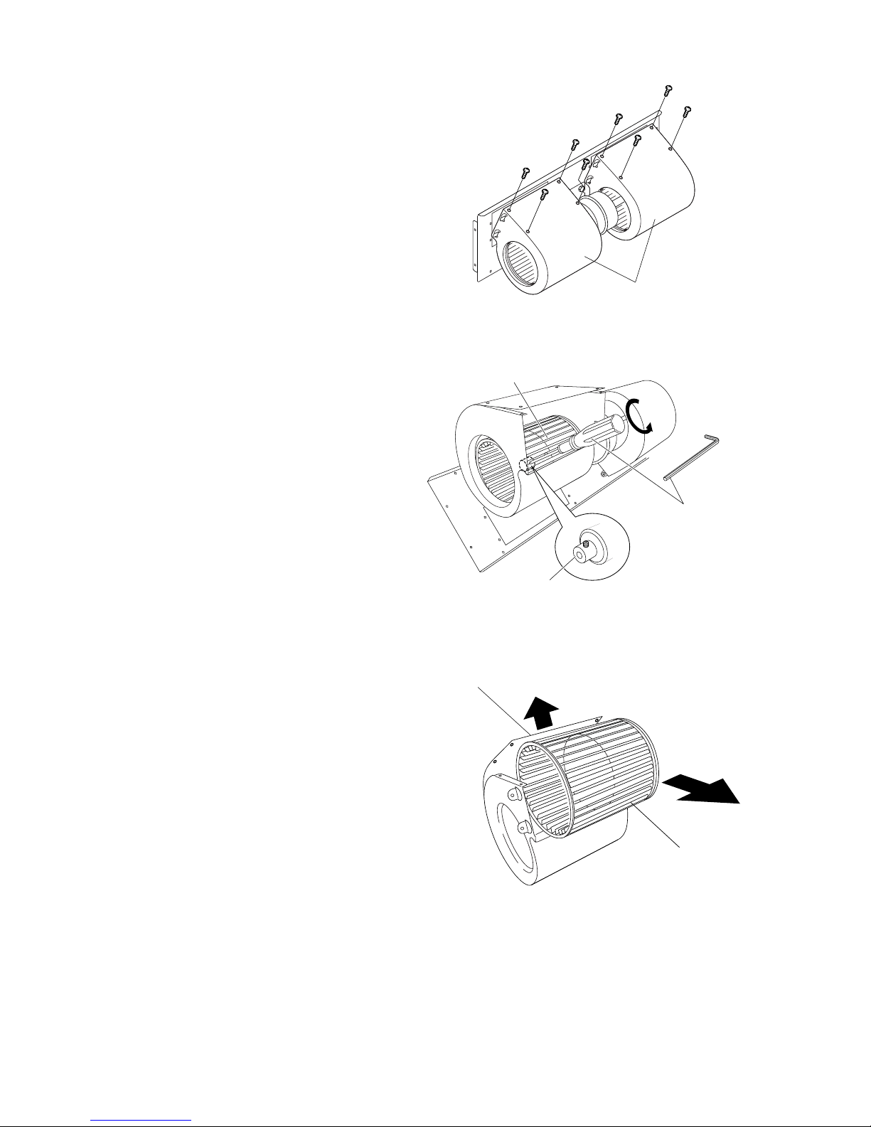
5-3. Removing Fan and Fan Motor
(1) Remove 8 screws holding the base plate for the fan
and fan motor. (Fig. 4)
(2) Remove 8 screws holding the fan casing.
Then pull the casing toward you. (Fig. 5)
Fan casing
Fig. 6
Base plate
Fig. 4
,,
SS
Evaporator
Fig. 3
15
(3) Remove 8 screws holding the fan casing. (Fig. 6)
(4) Insert a hex wrench in the fan boss and turn
it counterclockwise to loosen the fan.
(Fig. 7)
(5) Gently lift the opening of the fan motor casing
to access the fan.
(Fig. 8)
Fan casing
Fan
Fig. 8
Fan
Hex head screwdriver
or hex wrench (3.0 mm)
Fan boss
Fig. 7
Fan casing
Fig. 6
 Loading...