

Sanyo SAP-CRV93EHN,SAP-KRV93EH,SAP-KRV123EH,SAP-CRV123EHN Technical & Service Manual
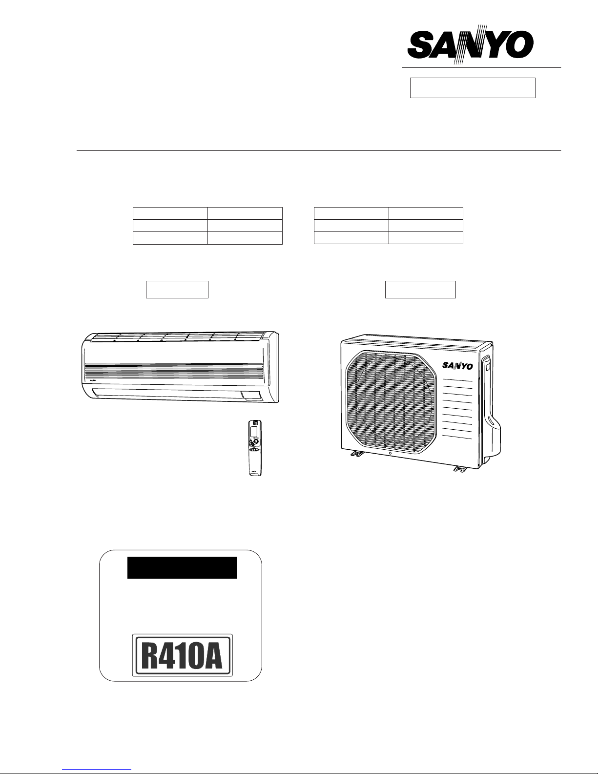
TECHNICAL & SERVICE MANUAL
SAP-KRV93EH + SAP-CRV93EHN
SAP-KRV123EH + SAP-CRV123EHN
DC INVERTER SPLIT SYSTEM AIR CONDITIONER
SAP-CRV93EHN
SAP-CRV123EHN
AIR CO
N
DITIONER
IMPORTANT
These air conditioners employ new
refrigerant R410A.
Pay special attention when
servicing the unit.
SAP-KRV93EH
SAP-KRV123EH
FILE NO.
REFERENCE NO. SM700598-01
Indoor Unit Outdoor Unit
Indoor Model No. Product Code No.
SAP-KRV93EH 1 852 089 81
SAP-KRV123EH 1 852 089 80
Outdoor Model No. Product Code No.
SAP-CRV93EHN 1 852 094 27
SAP-CRV123EHN 1 852 094 26
Destination: Nothen Europe
(Norway / Sweden / Finland / Denmark)
Sanyo ilmalämpöpumput korjaa ja huoltaa pääkaupunkiseudulla: Jäähdytinpalvelu RefGroup Oy
www.ilmalämpöpumput.com
2
IMPORTANT!
Please Read Before Starting
This air conditioning system meets strict safety and operating standards. As the installer or service person, it is an
important part of your job to install or service the system
so it operates safely and efficiently.
For safe installation and trouble-free operation, you
must:
●
Carefully read this instruction booklet before beginning.
●
Follow each installation or repair step exactly as
shown.
●
Observe all local, state, and national electrical codes.
●
Pay close attention to all warning and caution notices
given in this manual.
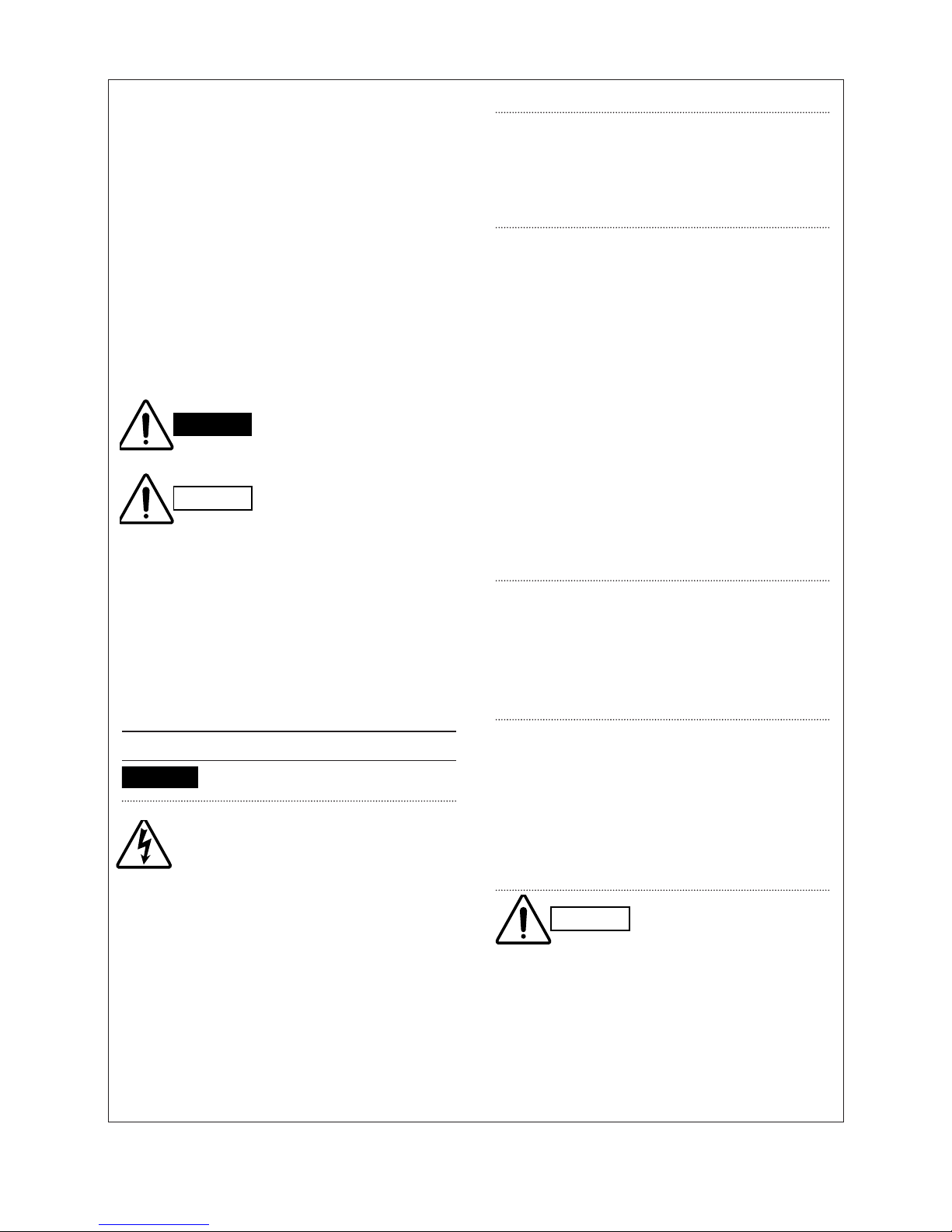
This symbol refers to a hazard or unsafe practice which
can result in severe personal
injury or death.
This symbol refers to a hazard
or unsafe practice which can
result in personal injury or
product or property damage.
If Necessary, Get Help
These instructions are all you need for most installation
sites and maintenance conditions. If you require help for
a special problem, contact our sales/service outlet or
your certified dealer for additional instructions.
In Case of Improper Installation
The manufacturer shall in no way be responsible for
improper installation or maintenance service, including
failure to follow the instructions in this document.
SPECIAL PRECAUTIONS
When Wiring
ELECTRICAL SHOCK CAN CAUSE SEVERE PER-
SONAL INJURY OR DEATH. ONLY A
QUALIFIED, EXPERIENCED ELECTRICIAN SHOULD ATTEMPT TO WIRE THIS
SYSTEM.
• Do not supply power to the unit until all wiring and tubing are completed or reconnected and checked.
• Highly dangerous electrical voltages are used in this
system. Carefully refer to the wiring diagram and
these instructions when wiring. Improper connections
and inadequate grounding can cause accidental
injury or death.
• Ground the unit following local electrical codes.
• Connect all wiring tightly. Loose wiring may cause
overheating at connection points and a possible fire
hazard.
When Transporting
Be careful when picking up and moving the indoor and
outdoor units. Get a partner to help, and bend your
knees when lifting to reduce strain on your back. Sharp
edges or thin aluminum fins on the air conditioner can
cut your fingers.
When Installing…
…In a Ceiling or Wall
Make sure the ceiling/wall is strong enough to hold the
unit’s weight. It may be necessary to construct a strong
wood or metal frame to provide added support.
…In a Room
Properly insulate any tubing run inside a room to prevent
“sweating” that can cause dripping and water damage to
walls and floors.
…In Moist or Uneven Locations
Use a raised concrete pad or concrete blocks to provide
a solid, level foundation for the outdoor unit. This prevents water damage and abnormal vibration.
…In an Area with High Winds
Securely anchor the outdoor unit down with bolts and a
metal frame. Provide a suitable air baffle.
…In a Snowy Area (for Heat Pump-type Systems)
Install the outdoor unit on a raised platform that is higher
than drifting snow. Provide snow vents.
When Connecting Refrigerant Tubing
• Use the flare method for connecting tubing.
• Apply refrigerant lubricant to the matching surfaces of
the flare and union tubes before connecting them,
then tighten the nut with a torque wrench for a leakfree connection.
• Check carefully for leaks before starting the test run.
When Servicing
• Turn the power OFF at the main power box (mains)
before opening the unit to check or repair electrical
parts and wiring.
• Keep your fingers and clothing away from any moving
parts.
• Clean up the site after you finish, remembering to
check that no metal scraps or bits of wiring have been
left inside the unit being serviced.
Others
• Ventilate any enclosed areas when installing or testing
the refrigeration system. Escaped refrigerant gas, on
contact with fire or heat, can produce dangerously
toxic gas.
• Confirm upon completing installation that no refrigerant gas is leaking. If escaped gas comes in contact
with a stove, gas water heater, electric room heater or
other heat source, it can produce dangerously toxic
gas.
WARNING
WARNING
CAUTION
CAUTION
Sanyo ilmalämpöpumput korjaa ja huoltaa pääkaupunkiseudulla: Jäähdytinpalvelu RefGroup Oy
www.ilmalämpöpumput.com

3
Table of Contents
Page
1. OPERATING RANGE................................................................................................................ 4
2. SPECIFICATIONS
2-1. Unit Specifications............................................................................................................ 5
2-2. Major Component Specifications...................................................................................... 7
2-3. Other Component Specifications...................................................................................... 11
3. DIMENSIONAL DATA................................................................................................................ 12
4. REFRIGERANT FLOW DIAGRAM
4-1. Refrigerant Flow Diagram................................................................................................. 14
5. PERFORMANCE DATA
5-1. Temperature Charts..........................................................................................................15
5-2. Air Throw Distance Charts ............................................................................................... 17
5-3. Operating Frequency Charts ............................................................................................ 19
6. ELECTRICAL DATA
6-1. Electrical Characteristics..................................................................................................23
6-2. Electric Wiring Diagrams.................................................................................................. 24
7. INSTALLATION INSTRUCTIONS
7-1. Installation Site Selection .................................................................................................26
7-2. Recommended Wire Length and Diameter ...................................................................... 28
7-3. Remote Control Unit Installation Position......................................................................... 29
7-4. How to Test Run the Air Conditioner ................................................................................ 30
7-5. Remove the Grille to Install the Indoor Unit...................................................................... 31
8. MAINTENANCE
8-1. Address Setting of the Remote Control Unit .................................................................... 32
8-2. Disconnecting and Connecting Positive Connector for Outdoor Unit............................... 33
9. FUNCTIONS
9-1. Operation Functions .........................................................................................................34
9-2. Protective Functions......................................................................................................... 36
10. TROUBLESHOOTING............................................................................................................... 38
11. CHECKING ELECTRICAL COMPONENTS
11-1. Measurement of Insulation Resistance............................................................................ 43
11-2. Checking Continuity of Fuse on PCB Ass’y...................................................................... 44
12. REFRIGERANT R410A:
SPECIAL PRECAUTIONS WHEN SERVICING UNIT............................................................... 45
INSTRUCTION MANUAL....................................................................................... 52
APPENDIX
Sanyo ilmalämpöpumput korjaa ja huoltaa pääkaupunkiseudulla: Jäähdytinpalvelu RefGroup Oy
www.ilmalämpöpumput.com

4
1. OPERATING RANGE
Temperature Indoor Air Intake Temp. Outdoor Air Intake Temp.
Cooling
Maximum 32°C D.B. / 23°C W.B. 43°C D.B.
Minimum 19°C D.B. / 14°C W.B. 19°C D.B.
Heating
Maximum 27°C D.B. 24°C D.B. / 18°C W.B.
Minimum 16°C D.B. –20°C D.B. / –20°C W.B.
Sanyo ilmalämpöpumput korjaa ja huoltaa pääkaupunkiseudulla: Jäähdytinpalvelu RefGroup Oy
www.ilmalämpöpumput.com
5
DATA SUBJECT TO CHANGE WITHOUT NOTICE.
Remarks: Rating conditions are:
Cooling: Indoor air temperature 27°C D.B. / 19°C W.B.
Outdoor air temperature 35°C D.B. / 24°C W.B.
Heating: Indoor air temperature 20°C D.B.
Outdoor air temperature 7°C D.B. / 6°C W.B.
2. SPECIFICATIONS
2-1. Unit Specifications
Indoor Unit SAP-KRV93EH
Outdoor Unit SAP-CRV93EHN
Power Source 220 – 240V Single-phase 50Hz
Performance Cooling Heating
Capacity kW 2.65 (0.9 – 3.2) 3.60 (0.9 – 5.0)
BTU/h 9,000 (3,100 – 10,900) 12,300 (3,100 – 17,100)
Air circulation (High) m3/h 480 530
Moisture removal (High) Liters/h 1.6 —
Electrical Rating Cooling Heating
Available voltage range V 198 – 264
Running amperes A 3.86 (1.28 – 5.88) 4.81 (1.21 – 6.47)
Power input W 755 (250 – 1,150) 995 (250 – 1,515)
Power factor % 85 90
C.O.P. W/W 3.51 3.62
Compressor locked rotor amperes A 15
Features
Controls / Temperature control Microprocessor / I.C. thermistor
Control unit Wireless remote control unit
Timer ON / OFF 24 hours & Daily program, 1-hour OFF
Fan speeds Indoor / Outdoor 3 and Auto / 1 (Hi)
Airflow direction (Indoor) Horizontal Manual
Vertical Auto
Air filter Washable, Anti-Mold
Compressor Rotary (DC inverter)
Refrigerant / Amount charged at shipment g R410A / 950
Refrigerant control Electric expansion valve
Operation sound Indoor: Hi/Me/Lo/Qt* dB-A 34 / 31 / 28 / 23 34 / 31 / 28 / 23
(*Qt=Quiet mode) Outdoor: Hi dB-A 46 47
Refrigerant tubing connections Flare type
Max allowable tubing length at shipment m 7.5
Refrigerant Narrow tube mm (in.) 6.35 (1/4)
tube diameter Wide tube mm (in.) 9.52 (3/8)
Refrigerant tube kit / Accessories Optional / Air clean filter
Voltage Rating 230V
Dimensions & Weight Indoor Unit Outdoor Unit
Unit dimensions Height mm 285 548
Width mm 825 720
Depth mm 189 265
Package dimensions Height mm 350 600
Width mm 900 856
Depth mm 255 362
Weight Net kg 9.0 34.0
Shipping kg 11.0 36.0
Shipping volume m
3
0.080 0.186
Sanyo ilmalämpöpumput korjaa ja huoltaa pääkaupunkiseudulla: Jäähdytinpalvelu RefGroup Oy
www.ilmalämpöpumput.com
6
Indoor Unit SAP-KRV123EH
Outdoor Unit SAP-CRV123EHN
DATA SUBJECT TO CHANGE WITHOUT NOTICE.
Remarks: Rating conditions are:
Cooling: Indoor air temperature 27°C D.B. / 19°C W.B.
Outdoor air temperature 35°C D.B. / 24°C W.B.
Heating: Indoor air temperature 20°C D.B.
Outdoor air temperature 7°C D.B. / 6°C W.B.
Power Source 220 – 240V Single-phase 50Hz
Performance Cooling Heating
Capacity kW 3.50 (0.9 – 3.8) 4.20 (0.9 – 5.8)
BTU/h 11,900 (3,100 – 13,000) 14,300 (3,100 – 19,800)
Air circulation (High) m3/h 500 530
Moisture removal (High) Liters/h 2.0 —
Electrical Rating Cooling Heating
Available voltage range V 198 – 264
Running amperes A 5.21 (1.19 – 6.21) 5.48 (1.18 – 7.09)
Power input W 1,090 (250 – 1,300) 1,165 (250 – 1,690)
Power factor % 91 92
C.O.P. W/W 3.21 3.61
Compressor locked rotor amperes A 15
Features
Controls / Temperature control Microprocessor / I.C. thermostat
Control unit Wireless remote control unit
Timer ON / OFF 24 hours & Daily program, 1-hour OFF
Fan speeds Indoor / Outdoor 3 and Auto / 1 (Hi)
Airflow direction (Indoor) Horizontal Manual
Vertical Auto
Air filter Washable, Anti-Mold
Compressor Rotary (DC inverter)
Refrigerant / Amount charged at shipment g R410A / 1,100
Refrigerant control Electric expansion valve
Operation sound Indoor: Hi/Me/Lo/Qt* dB-A 36 / 33 / 29 / 25 34 / 31 / 29 / 25
(*Qt=Quiet mode) Outdoor: Hi dB-A 47 49
Refrigerant tubing connections Flare type
Max allowable tubing length at shipment m 7.5
Refrigerant Narrow tube mm (in.) 6.35 (1/4)
tube diameter Wide tube mm (in.) 9.52 (3/8)
Refrigerant tube kit / Accessories Optional / Air clean filter
Voltage Rating 230V
Dimensions & Weight Indoor Unit Outdoor Unit
Unit dimensions Height mm 285 548
Width mm 825 720
Depth mm 189 265
Package dimensions Height mm 350 600
Width mm 900 856
Depth mm 255 362
Weight Net kg 9.0 35.0
Shipping kg 11.0 37.0
Shipping volume m
3
0.080 0.186
Sanyo ilmalämpöpumput korjaa ja huoltaa pääkaupunkiseudulla: Jäähdytinpalvelu RefGroup Oy
www.ilmalämpöpumput.com
7
2-2. Major Component Specifications
2-2-1. Indoor Unit
Indoor Unit SAP–KRV93EH
DATA SUBJECT TO CHANGE WITHOUT NOTICE.
Control PCB
Part No. CB-KRV93EH (POW-KRV93GJH)
Controls Microprocessor
Control circuit fuse 250V 3.15A
Flap Motor and Louver Motor
Type Stepping motor
Model MP24Z3-12V
Rating DC 12V
Coil resistance (Ambient temp. 25°C) Ω Each pair of terminals: 400 ± 7%
Heat Exchanger Coil
Coil Aluminum plate fin / Copper tube
Rows 2
Fin pitch mm 1.3
Face area m
2
0.188
Fan & Fan Motor
Type Fan / Fan motor Cross-flow / AC motor
Q’ty … Dia. and length mm 1 … D92 / L634
Fan motor model … Q’ty IBH-884-066 … 1
No. of poles … Rough measure rpm (Cool / Heat) 4 … 1,200 / 1,250
Nominal output W 30
Coil resistance (Ambient temp. 20°C) Ω BRN – WHT: 234
PNK (RED) – WHT: 209
— : —
Safety devices Type Thermal fuse
Operating temp. Open °C 130
Close Automatic reclosing
Run capacitor µF 1.2
VAC 440
Remote Control Unit RCS-3HVPSS4E
Sanyo ilmalämpöpumput korjaa ja huoltaa pääkaupunkiseudulla: Jäähdytinpalvelu RefGroup Oy
www.ilmalämpöpumput.com

8
Indoor Unit SAP–KRV123EH
DATA SUBJECT TO CHANGE WITHOUT NOTICE.
Control PCB
Part No. CB-KRV123EH (POW-KRV93GJH)
Controls Microprocessor
Control circuit fuse 250V 3.15A
Flap Motor and Louver Motor
Type Stepping motor
Model MP24Z3-12V
Rating DC 12V
Coil resistance (Ambient temp. 25°C) Ω Each pair of terminals: 400 ± 7%
Heat Exchanger Coil
Coil Aluminum plate fin / Copper tube
Rows 2
Fin pitch mm 1.3
Face area m
2
0.188
Fan & Fan Motor
Type Fan / Fan motor Cross-flow / AC motor
Q’ty … Dia. and length mm 1 … D92 / L634
Fan motor model … Q’ty IBH-884-066 … 1
No. of poles … Rough measure rpm (Cool / Heat) 4 … 1,250 / 1,250
Nominal output W 30
Coil resistance (Ambient temp. 20°C) Ω BRN – WHT: 234
PNK (RED) – WHT: 209
— : —
Safety devices Type Thermal fuse
Operating temp. Open °C 130
Close Automatic reclosing
Run capacitor µF 1.2
VAC 440
Remote Control Unit RCS-3HVPSS4E
Sanyo ilmalämpöpumput korjaa ja huoltaa pääkaupunkiseudulla: Jäähdytinpalvelu RefGroup Oy
www.ilmalämpöpumput.com
9
2-2-2. Outdoor Unit
Outdoor Unit SAP–CRV93EHN
DATA SUBJECT TO CHANGE WITHOUT NOTICE.
Compressor
Type DC Rotary (Hermetic)
Compressor model / Nominal output G4C090LU1ER / 600W
Compressor oil … Amount cc FV50S … 320
Coil resistance (Ambient temp. 20°C) Ω U – V: 0.81
V – W: 0.81
W – U: 0.81
Safety devices
CT (Peak current cut-off control) YES
Compressor discharge temp. control YES
Operation cut-off control in abnormal ambient temp. YES
Run capacitor µF —
VAC —
Crankcase heater —
Fan & Fan Motor
Type … Fan / Fan motor Propeller / AC motor
Q’ty … Dia. mm 1 … 400
Fan motor model … Q’ty IB-976-501 … 1
No. of poles … Rough measure rpm (Cool / Heat) 6 … 700 / 700
Nominal output W 20
Coil resistance (Ambient temp. 20°C) Ω WHT – BRN: 213
RED (PNK) – WHT: 168
— : —
Safety devices Type Thermal fuse
Operating temp. Open °C 150
Close °C Automatic reclosing
Run capacitor on control PCB (A) µF 2.0
VAC 440
Heat Exchanger Coil
Coil Aluminum plate fin / Copper tube
Rows 2
Fin pitch mm 1.4
Face area m
2
0.288
External Finish Acrylic baked-on enamel finish
Control PCB
Part No. CB-CRV93EHN (POW-CRV93GJH)
Controls Microprocessor
Control circuit fuse 250V, 20A
Sanyo ilmalämpöpumput korjaa ja huoltaa pääkaupunkiseudulla: Jäähdytinpalvelu RefGroup Oy
www.ilmalämpöpumput.com
10
Outdoor Unit SAP–CRV123EHN
DATA SUBJECT TO CHANGE WITHOUT NOTICE.
Fan & Fan Motor
Type … Fan / Fan Motor Propeller / DC Motor
Q’ty … Dia. mm 1 … 400
Fan motor model … Q’ty DAJ12-55J71-C … 1
No. of poles … Rough measure rpm (Cool / Heat) 8 … 750 / 750
Nominal output W 50
Coil resistance (Ambient temp. 20°C) Ω —
—
—
Safety devices Type —
Operating temp. Open °C —
Close °C —
Run capacitor on control PCB (A) µF —
VAC —
Heat Exchanger Coil
Coil Aluminum plate fin / Copper tube
Rows 2
Fin pitch mm 1.4
Face area m
2
0.367
External Finish Acrylic baked-on enamel finish
Control PCB
Part No. CB-CRV123EHN (POW-CRV123GJH)
Controls Microprocessor
Control circuit fuse 250V, 20A
Compressor
Type DC Rotary (Hermetic)
Compressor model / Nominal output G4C090LU1ER / 600W
Compressor oil … Amount cc FV50S … 320
Coil resistance (Ambient temp. 20°C) Ω U – V: 0.81
V – W: 0.81
W – U: 0.81
Safety devices
CT (Peak current cut-off control) YES
Compressor discharge temp. control YES
Operation cut-off control in abnormal ambient temp. YES
Run capacitor µF —
VAC —
Crankcase heater —
Sanyo ilmalämpöpumput korjaa ja huoltaa pääkaupunkiseudulla: Jäähdytinpalvelu RefGroup Oy
www.ilmalämpöpumput.com
11
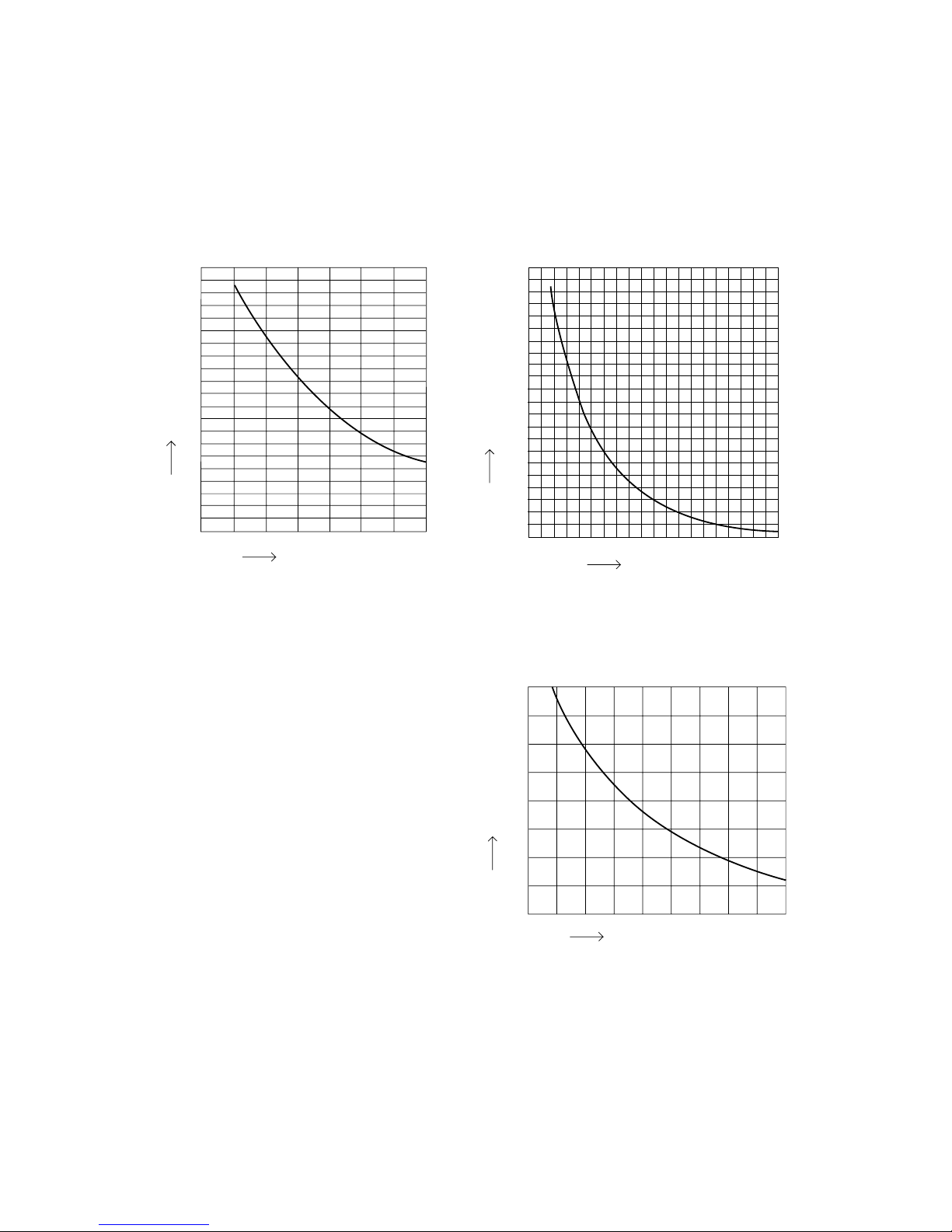
2-3. Other Component Specifications
Indoor Unit SAP–KRV93EH
SAP–KRV123EH
Outdoor Unit SAP–CRV93EHN
SAP–CRV123EHN
0
0 102030405060708090
40
60
80
100
120
140
160
180
200
20
10
1
2
3
4
5
6
7
8
9
10
15 20 25 30 35 40
• Indoor air temp sensor
• Indoor heat exchanger sensor
• Compressor temp sensor
Resistance (kΩ)
Resistance (kΩ)
Temperature (°C)
Temperature (°C)
• Outdoor air temp sensor
• Outdoor heat exchanger sensor
40
35
30
25
20
15
10
5
0
–20 –15 –10 –5 0 5 10 15 20
Temperature (°C)
Resistance (kΩ)
Sanyo ilmalämpöpumput korjaa ja huoltaa pääkaupunkiseudulla: Jäähdytinpalvelu RefGroup Oy
www.ilmalämpöpumput.com
12
5 5815
825
285
567
189 3
45
24.5 56
815
56 79.5
40
40
450187.5
178.9
Wide tube ø9.52(3/8")
Drain hose ø18
Narrow tube ø6.35(1/4")
187.5
178.9
86.5
86.5 45
360
(ø65)
308
187.5187.5
92.5122.5
70
825
450
45
285
40
(ø65)
24.5
40
196
46.5 27.4
70
32
133.8
52 23
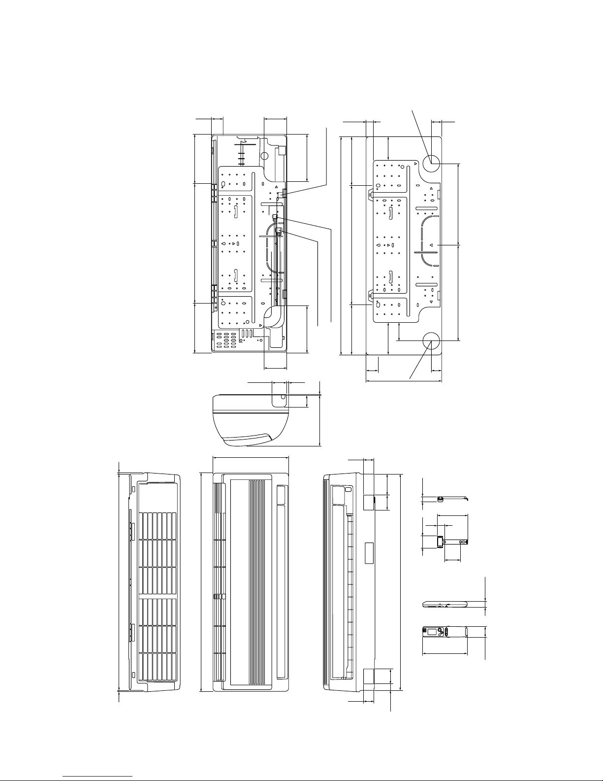
3. DIMENSIONAL DATA
Indoor Unit SAP-KRV93EH
SAP-KRV123EH
Unit: mm
Sanyo ilmalämpöpumput korjaa ja huoltaa pääkaupunkiseudulla: Jäähdytinpalvelu RefGroup Oy
www.ilmalämpöpumput.com
13
Outdoor Unit SAP-CRV93EHN
SAP-CRV123EHN
720 72
Wide tube service valve
ø9.52 (3/8")
2-ø12 holes
Narrow tube service valve
ø6.35 (1/4")
548
16
109 55
155
2
91
26591290
316
538
275
AIR DISCHARGE
(12 class only)
AIR INTAKE
AIR INTAKE
12
ID:2-ø23.6
ID:ø18
Unit: mm
Sanyo ilmalämpöpumput korjaa ja huoltaa pääkaupunkiseudulla: Jäähdytinpalvelu RefGroup Oy
www.ilmalämpöpumput.com
14
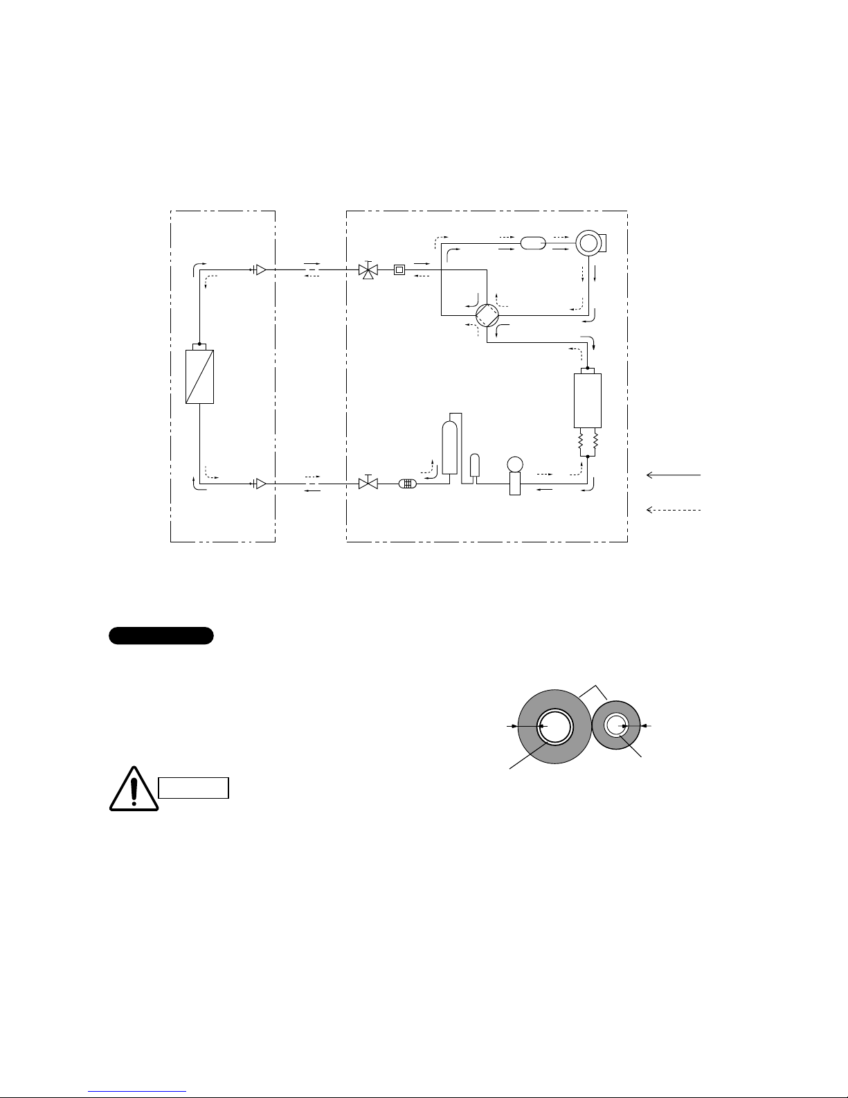
4. REFRIGERANT FLOW DIAGRAM
4-1. Refrigerant Flow Diagram
Indoor Unit SAP-KRV93EH Outdoor Unit SAP-CRV93EHN
SAP-CRV123EH SAP-CRV123EHN
Compressor
4-way
valve
Accumulator
Wide tube
service
valve
Wide tube
O.D.
ø9.52 mm
(3/8 ")
Narrow
tube
service
valve
Narrow tube
O.D.
ø6.35 mm
(1/4")
Heat exchanger
Heat exchanger
Muffler
Capillary
tube for
split flow
Cooling cycle
(Defrosting cycle)
Heating cycle
Indoor unit Outdoor unit
Electric
expansion
valve
Modulator
(12 class only)
Strainer
(9 class only)
Muffler
(12 class only)
M
Insulation of Refrigerant Tubing
Because capillary tubing is used in the outdoor unit, both the
wide and narrow tubes of this air conditioner become cold. To
prevent heat loss and wet floors due to dripping of
condensation, both tubes must be well insulated with a
proper insulation material. The thickness of the insulation
should be a min. 8 mm.
After a tube has been insulated,
never try to bend it into a narrow
curve because it can cause the tube
to break or crack.
IMPORTANT
Wide tube
Thickness:
Min. 8 mm
Insulation
Narrow tube
Thickness:
Min. 8 mm
IMPORTANT
CAUTION
Sanyo ilmalämpöpumput korjaa ja huoltaa pääkaupunkiseudulla: Jäähdytinpalvelu RefGroup Oy
www.ilmalämpöpumput.com
15
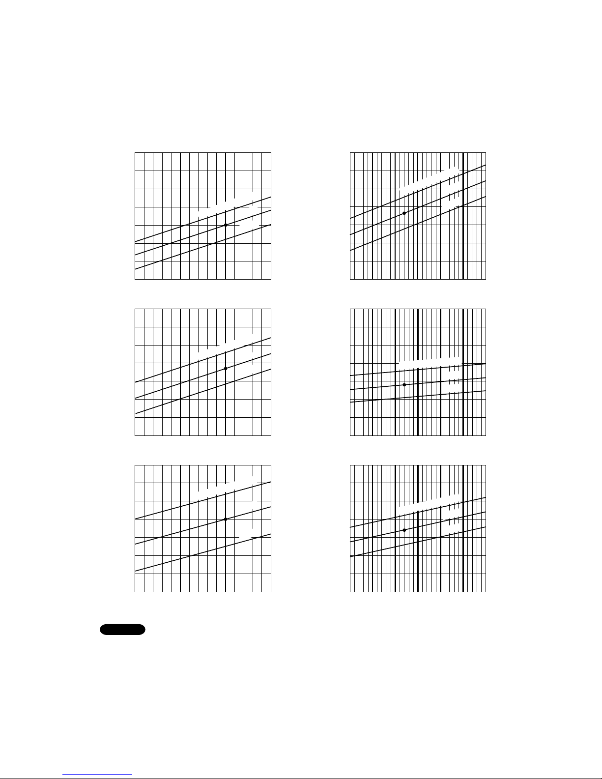
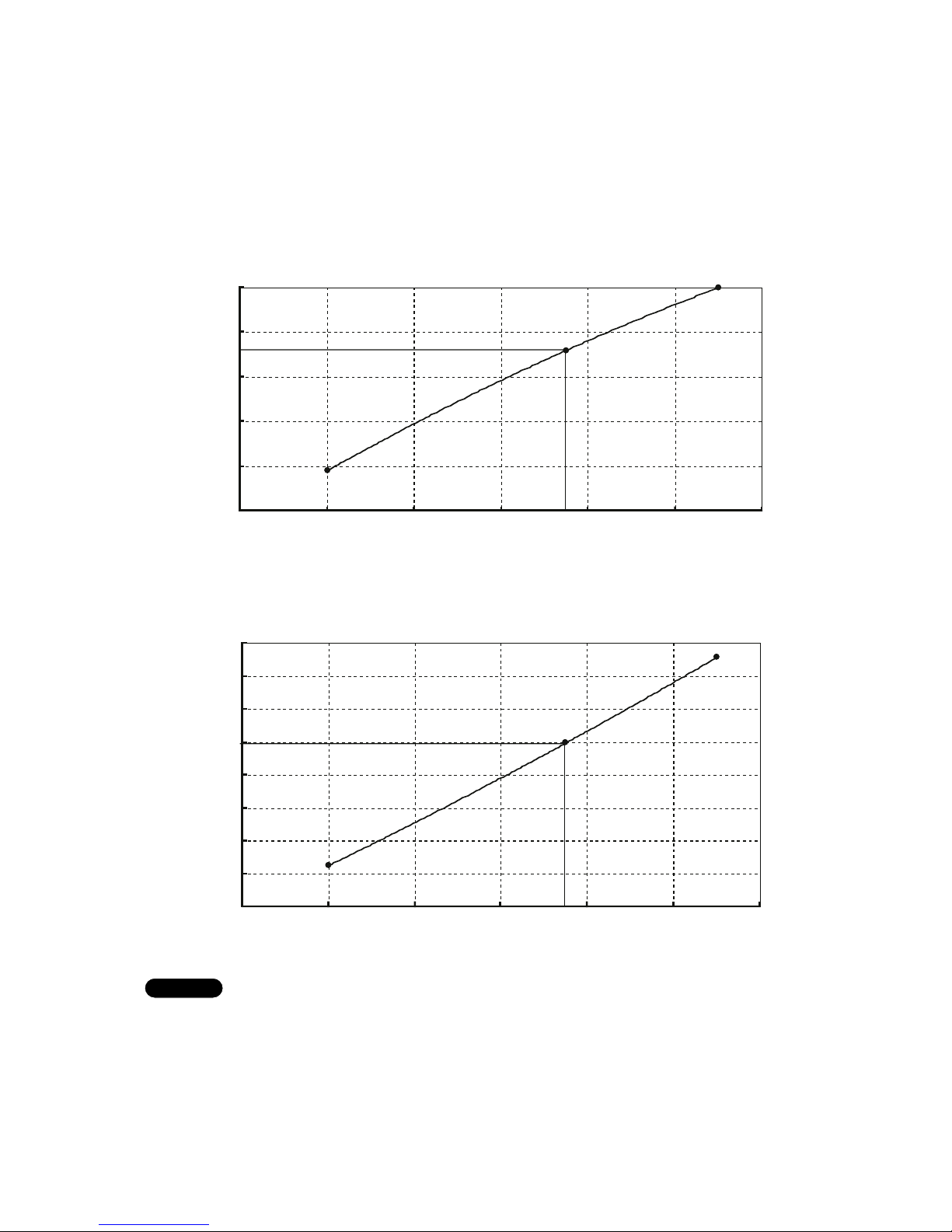
5. PERFORMANCE DATA
5-1. Temperature Charts
Indoor Unit SAP-KRV93EH
Outdoor Unit SAP-CRV93EHN
■ Cooling Characteristics ■ Heating Characteristics
25 30 35 40
25 30 35 40
17
16
15
14
13
12
11
10
–5 0 5 10 15 20 25
3
2
8
9
6
7
4
5
–5 0 5 10 15 20 25
60
55
50
45
40
35
30
25
Outdoor inlet air D.B. temp.(˚C)
Outdoor inlet air D.B. temp.(˚C) Outdoor inlet air D.B. temp.(˚C)
Outdoor inlet air D.B. temp.(˚C) Outdoor inlet air D.B. temp.(˚C)
Operating current (A)
Operating current (A)
Indoor discharge air temperature (˚C)
Indoor discharge air temperature (˚C)
–5 0 5 10 15 20 25
Outdoor inlet air D.B. temp.(˚C)
25 30 35 40
4
5
3
2
1.2
(11.2)
1.3
(12.2)
1.1
(10.2)
1.0
(9.2)
3.5
(34.7)
3.0
(29.6)
2.5
(24.5)
2.0
(19.4)
Low pressure at wide tube service valve
MPa (kgf/cm
2
G)
High pressure at wide tube service valve
MPa (kgf/cm
2
G)
27
°C
24
°C
Indoor Air Temp.30
°C
24
°C
27
°C
Indoor Air Temp.30
°C
27
°C
24
°C
Indoor Air Temp.30
°C
20
°C
17
°C
Indoor Air Temp.23°C
20
°C
17
°C
Indoor Air Temp.23
°C
20
°C
17
°C
Indoor Air Temp.23
°C
· Check each performance value in test-run mode. Electrical performance values represent a combined indoor/outdoor value.
· Overload prevention operates to protect the air conditioner when outdoor ambient temperature becomes extremely high in
heating mode. (Refer to “9-2. Overload prevention during heating.”)
● … Points of rating condition
Indoor air temperature 27°C D.B. / 19°C W.B. Heating: Indoor air temperature 20°C D.B.rating condition
Outdoor air temperature 35°C D.B. / 24°C W.B. Outdoor air temperature 7°C D.B. / 6°C W.B.
NOTE
Sanyo ilmalämpöpumput korjaa ja huoltaa pääkaupunkiseudulla: Jäähdytinpalvelu RefGroup Oy
www.ilmalämpöpumput.com
16
Indoor Unit SAP-KRV123EH
Outdoor Unit SAP-CRV123EHN
■ Cooling Characteristics ■ Heating Characteristics
Low pressure at wide tube service valve
MPa (kgf/cm
2
G)
High pressure at wide tube service valve
MPa (kgf/cm
2
G)
Outdoor inlet air D.B. temp.(˚C) Outdoor inlet air D.B. temp.(˚C)
Outdoor inlet air D.B. temp.(˚C) Outdoor inlet air D.B. temp.(˚C)
Outdoor inlet air D.B. temp.(˚C) Outdoor inlet air D.B. temp.(˚C)
Operating current (A)
Operating current (A)
Indoor discharge air temperature (˚C)
Indoor discharge air temperature (˚C)
25
1.3
(12.2)
1.0
(9.2)
1.1
(10.2)
30 35 40
1.2
(11.2)
Outdoor fan speed
HighLow
25
4
6
8
9
3
2
5
7
30 35 40
Outdoor fan speed
HighLow
25
8
10
12
14
16
18
30 35 40
Outdoor fan speed
HighLow
–5 0 5 10 15 20 25
2.0
(19.4)
2.5
(24.5)
3.0
(29.6)
3.5
(34.7)
–5 0 5
4
6
8
9
3
2
5
7
10 15 20 25
–5 0 5 10
30
6
25
35
40
45
50
55
20
60
15 20 25
27
°C
24
°C
Indoor Air Temp.30
°C
20
°C
17
°C
Indoor Air Temp.23
°C
Indoor Air Temp.23°C
17
°C
20
°C
Indoor Air Tem
p.30°C
24
°C
27
°C
17
°C
Indoor Air Temp.23
°C
20
°C
27
°C
24
°C
Indoor Air Temp.30°C
· Check each performance value in test-run mode. Electrical performance values represent a combined indoor/outdoor value.
· Overload prevention operates to protect the air conditioner when outdoor ambient temperature becomes extremely high in
heating mode. (Refer to “9-2. Overload prevention during heating.”)
● … Points of rating condition
Indoor air temperature 27°C D.B. / 19°C W.B. Heating: Indoor air temperature 20°C D.B.rating condition
Outdoor air temperature 35°C D.B. / 24°C W.B. Outdoor air temperature 7°C D.B. / 6°C W.B.
NOTE
Sanyo ilmalämpöpumput korjaa ja huoltaa pääkaupunkiseudulla: Jäähdytinpalvelu RefGroup Oy
www.ilmalämpöpumput.com
17
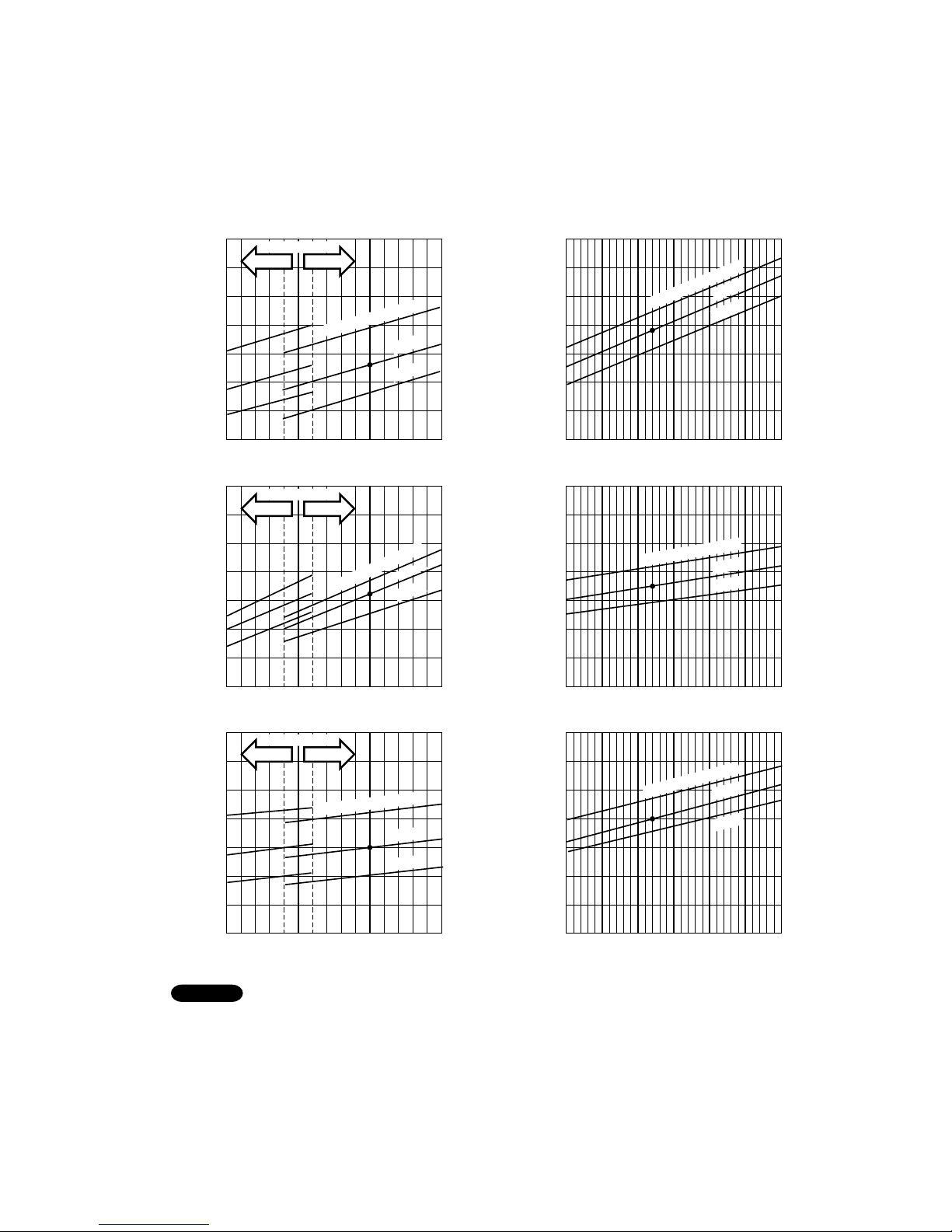
5-2. Air Throw Distance Charts
Horizontal distance (m)
Axis air velocity (m/s)
Vertical distance (m)
Room air temp. : 20°C
Fan speed : High
Heating
Horizontal distance (m)
Axis air velocity (m/s)
Vertical distance (m)
Room air temp. : 27°C
Fan speed : High
Cooling
1
2
3
4
123456789
: Flap angle 0° , : Axis air velocity 0°
: Flap angle 30°, : Axis air velocity 30°
1
2
3
4
123456789
: Flap angle 45° , : Axis air velocity 45°
: Flap angle 60° , : Axis air velocity 60°
Indoor Unit SAP–KRV93EH
Sanyo ilmalämpöpumput korjaa ja huoltaa pääkaupunkiseudulla: Jäähdytinpalvelu RefGroup Oy
www.ilmalämpöpumput.com
18
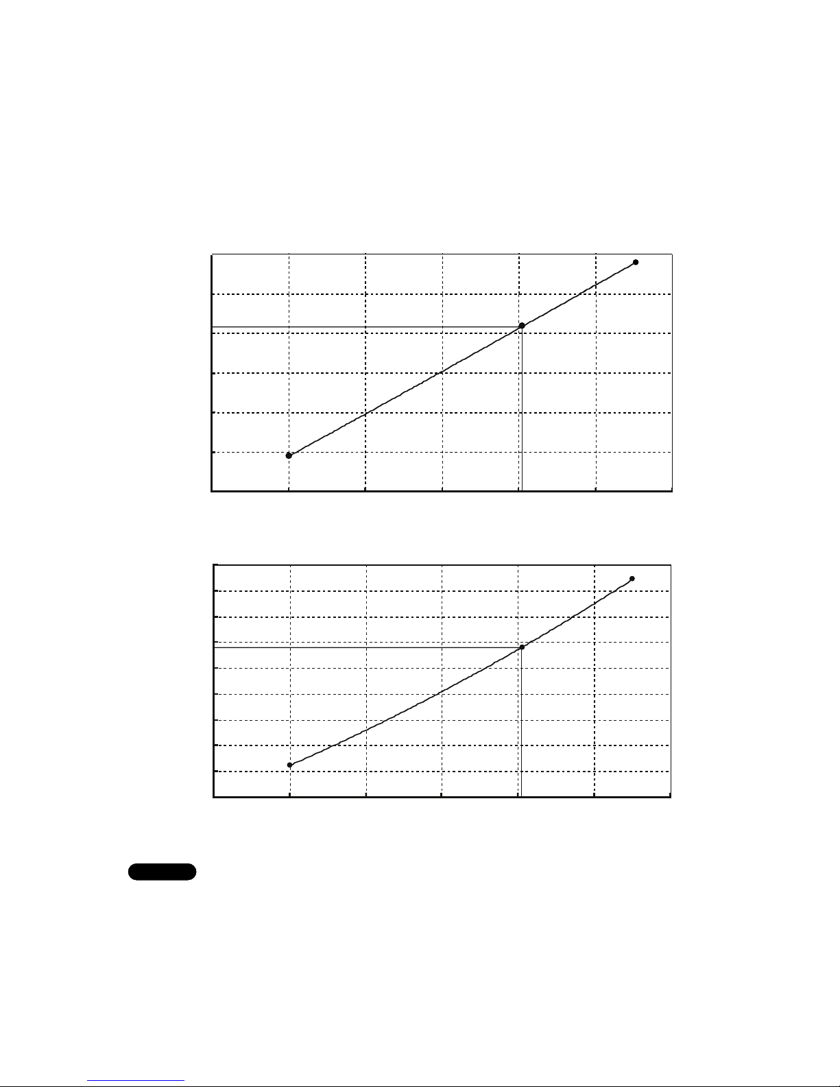
Horizontal distance (m)
Axis air velocity (m/s)
Vertical distance (m)
Room air temp. : 20°C
Fan speed : High
Heating
Horizontal distance (m)
Axis air velocity (m/s)
Vertical distance (m)
Room air temp. : 27°C
Fan speed : High
Cooling
1
2
3
4
123456789
: Flap angle 0° , : Axis air velocity 0°
: Flap angle 30°, : Axis air velocity 30°
1
2
3
4
123456789
: Flap angle 45° , : Axis air velocity 45°
: Flap angle 60° , : Axis air velocity 60°
Indoor Unit SAP–KRV123EH
Sanyo ilmalämpöpumput korjaa ja huoltaa pääkaupunkiseudulla: Jäähdytinpalvelu RefGroup Oy
www.ilmalämpöpumput.com
19
5-3. Operating Frequency Charts
0
1
2
3
4
5
0 1020304050607080
Operating Freqency (Hz)
Cooling Capacity (kW)
54
Min.
Center
Max.
0
200
400
600
800
1000
1200
0 1020304050607080
Operating Freqency (Hz)
Power Input (W)
54
Min.
Center
Max.
755
2.65
Indoor Unit SAP–KRV93EH
Outdoor Unit SAP–CRV93EHN
230V Single-phase 50Hz
NOTE
1) Rating conditions in cooling are:
Indoor: 27°C D.B. / 19°C W.B.
Outdoor: 35°C D.B. / 24°C W.B.
2) Fan speed: High
■ Cooling
Sanyo ilmalämpöpumput korjaa ja huoltaa pääkaupunkiseudulla: Jäähdytinpalvelu RefGroup Oy
www.ilmalämpöpumput.com
20
0
1
2
3
4
5
0 20406080100120
Operating Freqency (Hz)
Heating Capacity (kW)
3.6
Min.
Center
Max.
75
0
200
400
600
800
1000
1200
1400
1600
0 20406080100120
Operating Freqency (Hz)
Power Input (W)
995
Min.
Center
Max.
75
230V Single-phase 50Hz
NOTE
1) Rating conditions in heating are:
Indoor: 20°C D.B.
Outdoor: 7°C D.B. / 6°C W.B.
2) Fan speed: High
■ Heating
Sanyo ilmalämpöpumput korjaa ja huoltaa pääkaupunkiseudulla: Jäähdytinpalvelu RefGroup Oy
www.ilmalämpöpumput.com
21
0
1
2
3
4
5
0102030405060708090
Operating Freqency (Hz)
Cooling Capacity (kW)
3.5
Min.
Center
Max.
78
0
200
400
600
800
1000
1200
1400
0102030405060708090
Operating Freqency (Hz)
Power Input (W)
1090
Min.
Center
Max.
78
Indoor Unit SAP–KRV123EH
Outdoor Unit SAP–CRV123EHN
230V Single-phase 50Hz
NOTE
1) Rating conditions in cooling are:
Indoor: 27°C D.B. / 19°C W.B.
Outdoor: 35°C D.B. / 24°C W.B.
2) Fan speed: High
■ Cooling
Sanyo ilmalämpöpumput korjaa ja huoltaa pääkaupunkiseudulla: Jäähdytinpalvelu RefGroup Oy
www.ilmalämpöpumput.com
22
0
1
2
3
4
5
6
0 20406080100120
Operating Freqency (Hz)
Heating Capacity (kW)
4.2
Min.
Center
Max.
81
0
200
400
600
800
1000
1200
1400
1600
1800
0 20406080100120
Operating Freqency (Hz)
Power Input (W)
1165
Min.
Center
Max.
81
230V Single-phase 50Hz
NOTE
1) Rating conditions in heating are:
Indoor: 20°C D.B.
Outdoor: 7°C D.B. / 6°C W.B.
2) Fan speed: High
■ Heating
Sanyo ilmalämpöpumput korjaa ja huoltaa pääkaupunkiseudulla: Jäähdytinpalvelu RefGroup Oy
www.ilmalämpöpumput.com
23
6. ELECTRICAL DATA
6-1. Electrical Characteristics
Indoor Unit SAP-KRV93EH
Outdoor Unit SAP-CRV93EHN
Indoor Unit Outdoor Unit Complete Unit
Fan Motor Fan Motor Compressor
Performance at 230V Single-phase 50Hz
Rating conditions Running amp. A 0.17
Power input kW 0.033
0.21
0.048
Rating conditions: Indoor air temperature: 27°C D.B. / 19°C W.B.
Outdoor air temperature: 35°C D.B.
Rating conditions: Indoor air temperature 20°C D.B.
Outdoor air temperature 7°C D.B. / 6°C W.B.
Heating
Cooling
3.48
0.674
3.86
0.755
Indoor Unit Outdoor Unit Complete Unit
Fan Motor Fan Motor Compressor
Performance at 230V Single-phase 50Hz
Rating conditions Running amp. A 0.17
Power input kW 0.035
0.21
0.048
4.43
0.912
4.81
0.995
Indoor Unit SAP-KRV123EH
Outdoor Unit SAP-CRV123EHN
Indoor Unit Outdoor Unit Complete Unit
Fan Motor Fan Motor Compressor
Performance at 230V Single-phase 50Hz
Rating conditions Running amp. A 0.17
Power input kW 0.035
0.14
0.030
Rating conditions: Indoor air temperature: 27°C D.B. / 19°C W.B.
Outdoor air temperature: 35°C D.B.
Rating conditions: Indoor air temperature: 20°C D.B.
Outdoor air temperature: 7°C D.B. / 6°C W.B.
Heating
Cooling
4.90
1.025
5.21
1.090
Indoor Unit Outdoor Unit Complete Unit
Fan Motor Fan Motor Compressor
Performance at 230V Single-phase 50Hz
Rating conditions Running amp. A 0.17
Power input kW 0.035
0.14
0.030
5.17
1.100
5.48
1.165
Sanyo ilmalämpöpumput korjaa ja huoltaa pääkaupunkiseudulla: Jäähdytinpalvelu RefGroup Oy
www.ilmalämpöpumput.com
24
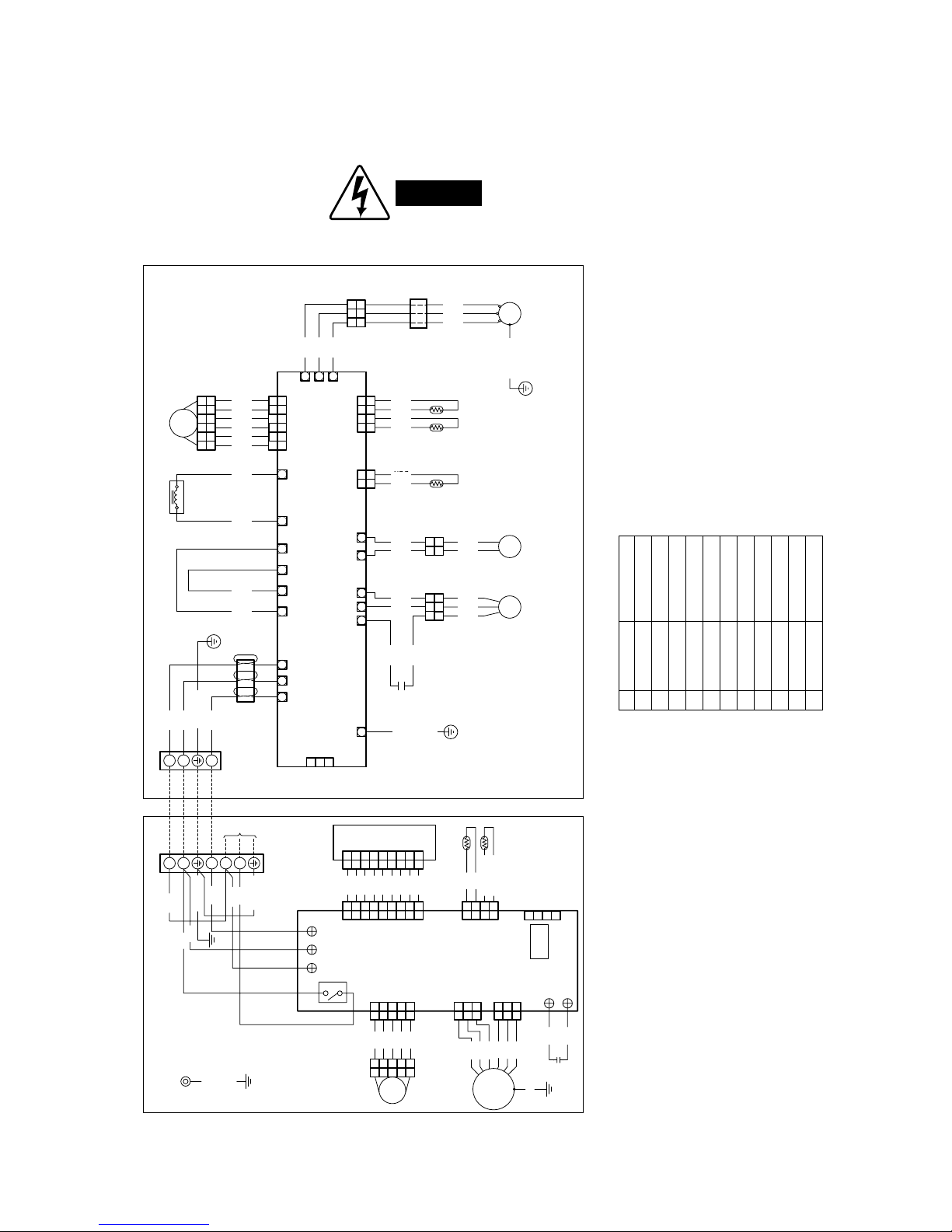
6-2. Electric Wiring Diagrams
Indoor Unit SAP-KRV93EH
Outdoor Unit SAP-CRV93EHN
WARNING
To avoid electrical shock hazard, be sure to
disconnect power before checking, servicing
and/or cleaning any electrical parts.
5
5
4
4
3
3
2
2
1
1
4
4
3
3
2
2
1
1
2
2
1
1
6
6
5
5
4
4
3
3
2
2
1
1
6
6
W W W W W W
WWWWW
W
WWW
W W
321
3
3
2
2
1
1
3
3
2
2
1
1
1
1
2
2
RV
YEL
YEL
BLK
BLK
BLK
BLK
COMPRESSOR
THERMISTOR
FERRITE CORE
COIL
THERMISTOR
OUTDOOR
THERMISTOR
YL2P
CONNECTOR
OUTDOORRV1RV2
MV
(BLK)
MAGNETIC COILREACTANCE
L2L1IN+IN–OUT–OUT+IN1IN2S1
CE
W
U
V
T-RUN/TEST
FM FM H
(WHT)
COIL/COMP
(WHT)
BLK
BLK
BLU
BLU
BRN
WHT
BLU
BLU
BLU
YL3P
CONNECTOR
VL3P
CONNECTOR
BRN
WHT
(PNK)
RED
4-WAY VALVE
FM
FAN MOTOR
CAPACITOR
W
BLU
WHT
RED
WHT
BLU
(PNK)
RED
CM
COMPRESSOR
MOTOR
GRN/YEL
S/U C/W
R
/
V
GRN/YEL
GRN/YEL
BLK
WHT
RED
ORG
BLK
WHT
WHT
ORG
RED
GRY
WHT
YEL
BLK
FERRITE
CORE
TERMINAL
BASE
MV
RED
CONTROLLER
Outdoor Unit : SAP-CRV93EHIndoor Unit : SAP-KRV93EH
8FA-2-5257-145XX-0
YEL
BRN
BLU
PNK
RED
BRN
BRN
TERMINAL BASE
POWER
SUPPLY
BLU
EARTH
RED
GRY
GRY
EVAPORATOR
54321
554433
BLK
BLK
2 2
1 1
4 4
3 3
22
11
CONTROLLER
THERMISTOR
(ROOM)
THERMISTOR
(COIL)
8FA-2-5257-143XX-2
FLAP
LAMP
9P(WHT)
IND LAMP ASSY
FAN
5P(WHT)
FLAP
5P(WHT)
POWER
RELAY
RY01
HALL IC
3P(WHT)
FMC1
FMC2
4P(WHT)
ROOM/COIL
4P(WHT)
BLK
RED
WHT
(RED)
PNK
22
YEL
BLU
GRN/YEL
FAN MOTOR
CAPACITOR
FAN MOTOR
FLAP MOTOR
PNK
33
11
553311
32154
WHT
WHT
WHT
554433
22
11
77
66
5 5
WHT
WHT
WHT
4 4
3 3
RED
2 2
1 1
7 7
6 6
99
88
WHT
WHT
9 9
88
BLK(ORG)
BLK(ORG)
1
234
BRN
FM
HA
JEM-A
1
2
4
L
N
4
AC IN SI1 SI
3
GRN/YEL
GRN/YEL
GRN/YEL
1
2
4
Meaning of Abbreviations
ABBREV. MEANING
1 BLK BLACK
2 BLU BLUE
3 BRN BROWN
4 GRN/YEL GREEN/YELLOW
5 GRY GREY
6 ORG ORANGE
7 PNK PINK
8 RED RED
9 VLT VIOLET
10 WHT WHITE
11 YEL YELLOW
Sanyo ilmalämpöpumput korjaa ja huoltaa pääkaupunkiseudulla: Jäähdytinpalvelu RefGroup Oy
www.ilmalämpöpumput.com
 Loading...