

Sanyo SAP-CMRV3656EH Technical & Service Manual
TECHNICAL & SERVICE MANUAL
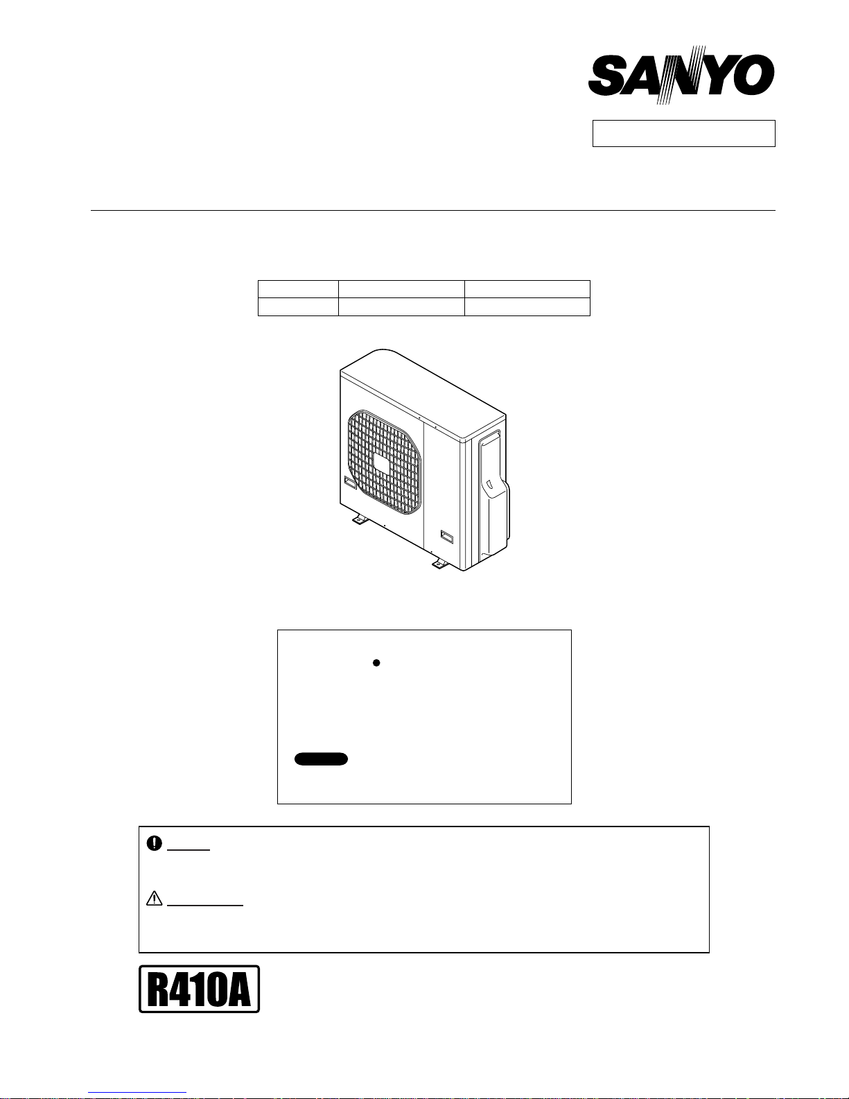
OUTDOOR UNIT : SAP-CMRV3656EH
SAP-CMRV3656EH
DC INVERTER MULTI-SYSTEM AIR CONDITIONER
Outdoor Model No.
SAP-CMRV3656EH-F
Capacity
10.0kW
Product Code No.
1 852 355 48
REFERENCE NO. SM700847
< Applicable Indoor Units >
Wall mounted type
For details about the combination, refer to
"Unit Combination Table" in the Appendix of this manual.
SAP-KRV96EHDSA
SAP-KRV126EHDS
NOTE
SAP-KMRV76EH
SAP-KMRV96EH
SAP-KMRV126EH
SAP-KRV186EH
SAP-KRV246EH
Destination: Europe
RoHS
WARNING
• This product does not contain any hazardous substances prohibited by the RoHS Directive.
• You are requested to use RoHS compliant parts for maintenance or repair.
• You are requested to use lead-free solder.
Do not vent R410A into atmosphere : R410A is a fluorinated greenhouse gas,
covered by Kyoto Protocol, with a Global Warming Potential (GWP) = 1975.
F-GAS REGULATION (EC) No 842 / 2006
FILE NO.
When Wiring
ELECTRICAL SHOCK CAN CAUSE
SEVERE PERSONAL INJURY OR DEATH.
ONLY A QUALIFIED, EXPERIENCED
ELECTRICIAN SHOULD ATTEMPT TO
WIRE THIS SYSTEM.
SPECIAL PRECAUTIONS
This symbol refers to a hazard
or unsafe practice which can
result in severe personal
injury or death.
This symbol refers to a hazard
or unsafe practice which can
result in personal injury or
product or property damage.
CAUTION
CAUTION
WARNING
WARNING
Important!
Please Read Before Starting
This air conditioning system meets strict safety and
operating standards. As the installer or service person, it
is an important part of your job to install or service the
system so it operates safely and efficiently.
For safe installation and trouble-free operation, you
must:
Carefully read this instruction booklet before beginning.
Follow each installation or repair step exactly as shown.
Observe all local, state, and national electrical codes.
Pay close attention to all warning and caution notices
given in this manual.
If Necessary, Get Help
These instructions are all you need for most installation
sites and maintenance conditions. If you require help for
a special problem, contact our sales/service outlet or
your certified dealer for additional instructions.
In Case of Improper Installation
The manufacturer shall in no way be responsible for
improper installation or maintenance service, including
failure to follow the instructions in this document.
Do not supply power to the unit until all wiring and
tubing are completed or reconnected and checked.
Highly dangerous electrical voltages are used in this
system. Carefully refer to the wiring diagram and these
instructions when wiring. Improper connections and
inadequate grounding can cause accidental injury or
death.
Ground the unit following local electrical codes.
Connect all wiring tightly. Loose wiring may cause
overheating at connection points and a possible fire
hazard.
Install a protective leakage breaker depending on the
installation location (especially a damp or humid
location). If a leakage breaker is not installed, electric
shock can occur.
When Transporting
Be careful when picking up and moving the indoor and
outdoor units. Get a partner to help, and bend your knees
when lifting to reduce strain on your back. Sharp edges or
thin aluminum fins on the air conditioner can cut your
fingers.
When Installing
In a Ceiling or Wall
Make sure the ceiling/wall is strong enough to hold the
unit’s weight. It may be necessary to construct a strong
wood or metal frame to provide added support.
In a Room
Properly insulate any tubing run inside a room to prevent
"sweating" that can cause dripping and water damage to
walls and floors.
In Moist or Uneven Locations
Use a raised concrete pad or concrete blocks to provide a
solid, level foundation for the outdoor unit. This prevents
water damage and abnormal vibration.
In an Area with High Winds
Securely anchor the outdoor unit down with bolts and a
metal frame. Provide a suitable air baffle.
In a Snowy Area
Install the outdoor unit on a raised platform that is higher
than drifting snow. Provide snow vents.
When Connecting Refrigerant Tubing
Use the flare method for connecting tubing.
Apply refrigerant lubricant to the matching surfaces of
the flare and union tubes before connecting them, then
tighten the nut with a torque wrench for a leak-free
connection.
Check carefully for leaks before starting the test run.
When Servicing
Turn the power off at the main power box (mains) before
opening the unit to check or repair electrical parts and
wiring.
Keep your fingers and clothing away from any moving
parts.
Clean up the site after you finish, remembering to check
that no metal scraps or bits of wiring have been left
inside the unit being serviced.
Others
Ventilate any enclosed areas when installing or testing
the refrigeration system. Escaped refrigerant gas, on
contact with fire or heat, can produce dangerously toxic
gas.
Confirm upon completing installation that no refrigerant
gas is leaking. If escaped gas comes in contact with a
stove, gas water heater, electric room heater or other
heat source, it can produce dangerously toxic gas.
•
•
•
•
•
•
•
•
•
•
•
•
•
2

Table of Contents
APPLICABLE INDOOR UNITS
1. OPERATING RANGE
2. SPECIFICATIONS
2-1. Unit Specifications
2-2. Major Component Specifications
2-3. Other Component Specifications
3. DIMENSIONAL DATA
4. REFRIGERANT FLOW DIAGRAM
4-1. Refrigerant Flow Diagram
5. PERFORMANCE DATA
5-1. Te mperature Charts
6. ELECTRICAL DATA
6-1. Electric Wiring Diagrams
7. FUNCTIONS
7-1. Explanation of Functions
7-2. Protective Functions
7-3. Special Functions
8. TROUBLESHOOTING
8-1. Precautions before Performing Inspection or Repair
8-2. Self-Diagnostics
8-3. Checking the Outdoor System
8-4. Trouble Diagnosis of Each Part
8-5. Trouble Diagnosis of Fan Motor
9. REFRIGERANT R410A:
SPECIAL PRECAUTIONS WHEN SERVICING UNIT
9-1. Characteristics of New Refrigerant R410A
9-2. Checklist before Servicing
9-3. Tools Specifically for R410A
9-4. Tubing Installation Procedures
9-5. In Case of Compressor Malfunction
9-6. In Case Refrigerant is Leaking
9-7. Charging Additional Refrigerant
9-8. Retro-Fitting Existing Systems
5
6
7
8
9
10
11
12
17
18
22
25
27
28
30
31
34
35
35
37
37
38
40
41
41
....................................................................................................
...................................................................................................................
.............................................................................................................
.......................................................................................
.......................................................................................
...................................................................................................................
...................................................................................................
............................................................................................................
....................................................................................................
....................................................................................................
...........................................................................................................
...............................................................................................................
...........................................................
..................................................................................................................
............................................................................................
..........................................................................................
..........................................................................................
.........................................................................
...................................................................................................
................................................................................................
............................................................................................
....................................................................................
............................................................................................
..........................................................................................
............................................................................................
Page
3

APPENDIX A INSTALLATION INSTRUCTIONS
APPENDIX B UNIT COMBINATION TABLES
A-1
A-2
.............................................................................
.................................................................................
Page
4
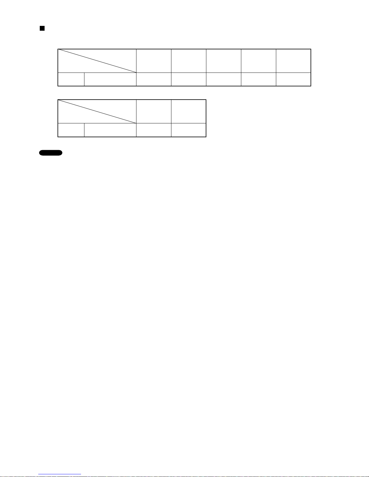
APPLICABLE INDOOR UNITS
SAP-CMRV3656EH
Multi-Outdoor Unit
Indoor Unit
YES YES YES YES YES5-Room
SAPKMRV76EH
SAPKMRV96EH
SAPKMRV126EH
SAPKRV186EH
SAPKRV246EH
SAP-CMRV3656EH
Multi-Outdoor Unit
Indoor Unit
YES YES5-Room
SAPKRV96EHDSA
SAPKRV-126EHDS
NOTE
1. The table lists the wall-mounted type of indoor units as representative models.
2. For details on the applicable indoor units other than the wall-mounted type, refer to the catalog.
5
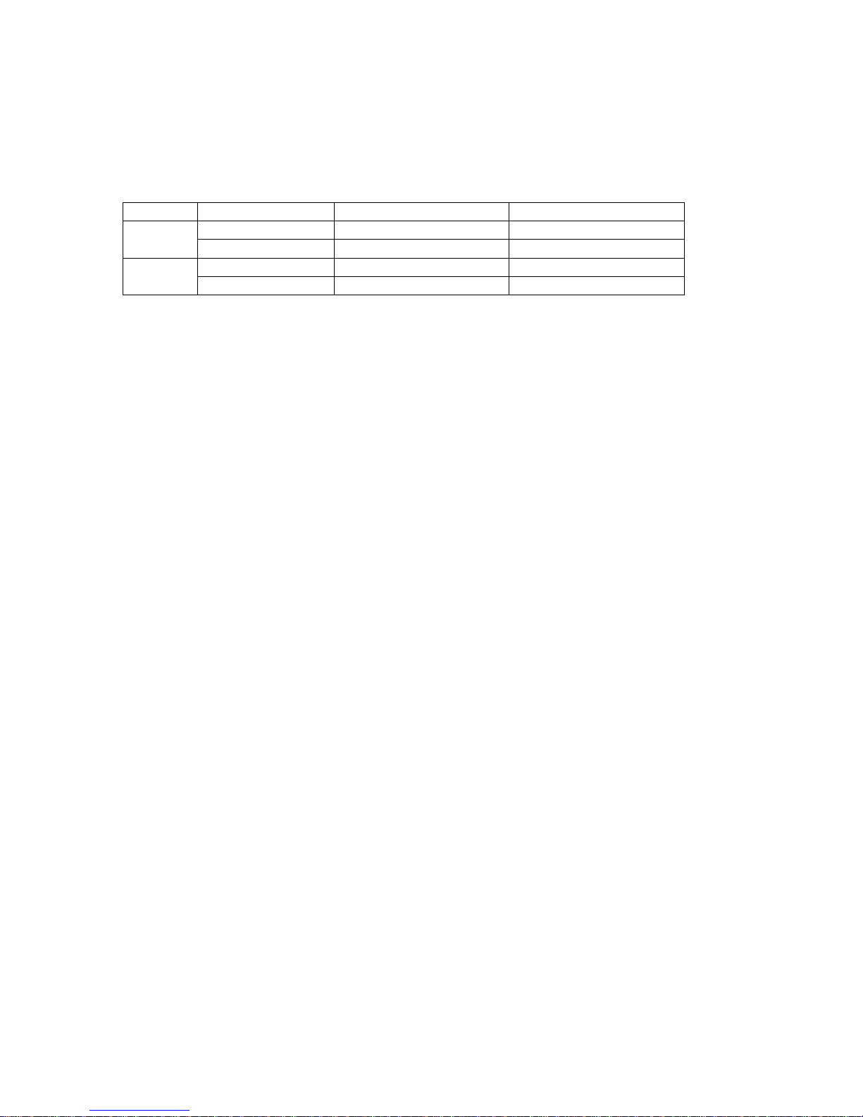
1. OPERATING RANGE
Maximum
Minimum
Maximum
Minimum
32 °C D.B. / 23 °C W.B.
19 °C D.B. / 14 °C W.B.
27 °C D.B.
16 °C D.B.
43 °C D.B.
-
10 °C D.B.
24 °C D.B. / 18 °C W.B.
_
D.B. /
-
15 °C W.B.
Temperature Indoor Air Intake Temp. Outdoor Air Intake Temp.
Cooling
Heating
Outdoor Unit : SAP-CMRV3656EH
Indoor Unit : SAP-KMRV76EH, SAP-KMRV96EH, SAP-KMRV126EH
SAP-KRV186EH, SAP-KRV246EH
SAP-KRV96EHDSA, SAP-KRV126EHDS
6
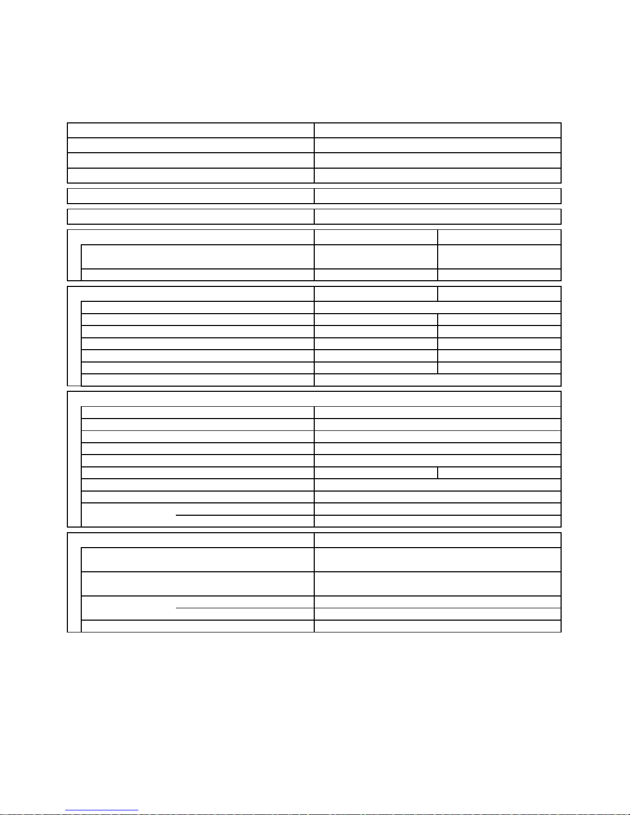
2. SPECIFICATIONS
2-1. Unit Specifications
Outdoor Unit SAP-CMRV3656EH
Indoor Unit SAP-KMRV76EH
× 5
DATA SUBJECT TO CHANGE WITHOUT NOTICE.
Remarks:
1. The values shown in perfromance section and electrical rating section above are based on the following unit combination.
For other combination unit, please refer to the "Unit Combination Table" in this manual.
Indoor Unit: SAP-KMRV76EH 5units Outdoor Unit: SAP-CMRV3656EH 1unit
2. Rating conditions are: Cooling: Indoor air temp. 27°C D.B. / 19°C W.B.
Outdoor air temp. 35°C D.B. / 24°C W.B.
Heating: Indoor air temp. 20°C D.B.
Outdoor air temp. 7°C D.B. / 6°C W.B.
Operation Sound Hi dB-A
Refrigerant Control
( 4.0 to 14.5 )
( 13,600 to 49,500 )
12.6
2,860
12.6
2,860
10.0
34,100
12.0
40,900
( 3.5 to 11.5 )
( 11,900 to 39,200 )
Shipping Volume
Cooling Heating
Cooling Heating
Net
Shipping
Weight
Height
× Width × Depth
kg
kg
m
3
mm
230V
198 to 264
Dimensions & Weight (Outdoor Unit)
Refrigerant Tubing Connections
Unit Dimensions
Electrical Rating
Air Circulation (High)
WPower Input
V
A
Available Voltage Range
Running Amperes
Narrow tube
Wide tube
Refrigerant mm (in.)
Tube Diameter mm (in.)
97.0
103.0
0.50
910
× 940 × 340
6.35 (1/4")
× 5
9.52 (3/8")
× 3 + 12.7 (1/2") × 2
mMax. allowable tubing length per unit
Flare Type
30
Electric Expansion Valve
Compressor
Refrigerant / Amount charged at shipment kg
DC Twin Rotary (Inverter)
R410A / 4.1
Controls
Fan Speeds
Microprocessor
Auto (Hi / Variable)
Features (Outdoor Unit)
C.O.P.
Compressor Locked Rotor Amperes
W/W
kW
Performance
- 4.20
50 53
%Power Factor 99 99
A 19.5
Type
Voltage Rating
BTU/h
Capacity
m
3
/h
5-Room Multi Outdoor Unit
E.E.R. W/W 3.50 -
Number of Connectable Indoor Units 5
Number of Operatable Indoor Units 5
Max. Capacity of Operating Indoor Units kW 17.55
Power Source 220 to 240V Single-Phase 50Hz
Height × Width × Depth mm
Package Dimensions
1,031 × 1,086 × 448
7
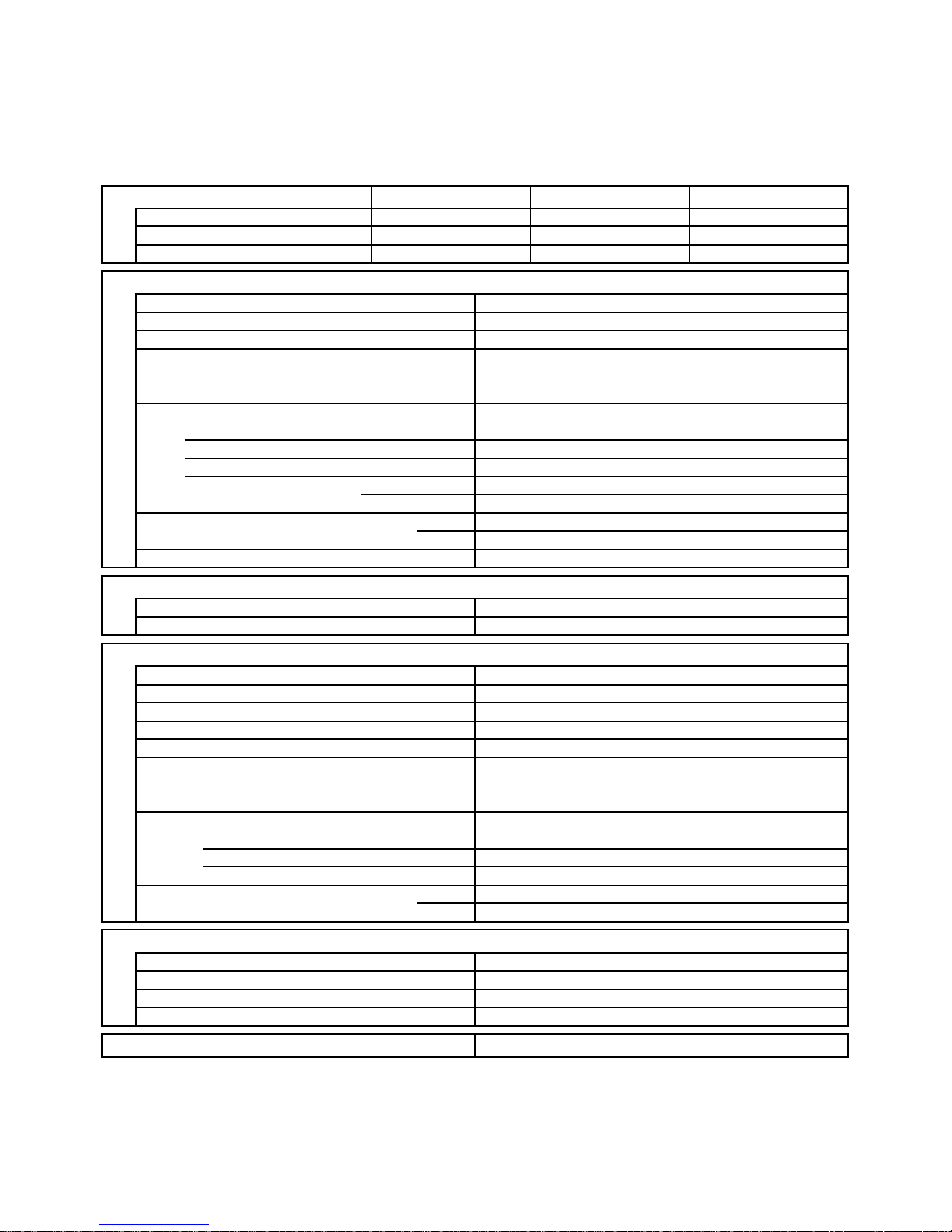
P.C.Board
Circuit Fuse
Controls
Part No.
Microprocessor
400V 3.15A
CB-CMRV3656EH
Control P.C.B
-
250V 25A
POW-CMRV3656EH-B1
Noise Filter P.C.B
-
-
POW-CMRV3656EH-C1
H.I.C.Board
1 ... D490
Propeller
DC Motor
SIC-71FW-D881-1 ... 1
8
-
81
750 / 700
Internal Controller
Yes
Yes
-
-
Aluminum Plate Fin / Copper Tube
2
1.2
0.792
Fan
Q'ty ... Dia.
Type
mm
Fan Motor
Nominal Output
Coil Resistance
Rough Measure RPM (Cool:Hi / Heat:Hi)
Type
Model ... Q'ty
No. of Poles
Safety Device
Type
Over- Current Protection
Over- Heat Protection
(Ambient Temp. 20 °C)
Run Capacitor Micro F
VAC
W
Ohm
Face Area
Coil
Rows
Fin Pitch
Heat Exchanger Coil
m
2
mm
DATA SUBJECT TO CHANGE WITHOUT NOTICE.
2-2. Major Component Specifications
2-2-1. Outdoor Unit
Outdoor Unit SAP-CMRV3656EH
C-9RVN273H0H / 2,700W
DC Twin Rotary (Hermetic)
Compressor
Compressor Model / Nominal Output
Type
FV68S ... 1,400Compressor Oil ... Amount CC
T - R : 0.169Coil Resistance (Ambient Temp. 25 °C) Ohm
T - S : 0.169
R - S : 0.169
Safety Device
YesCT (Peak current cut-off control)
YesCompressor Discharge Temp. Control
Yes
Operation cut-off control in abnormal ambient Temp.
CS-7LOverload Relay
Open : 115 °C, Close : 100 °C
Model
Operation Temp.
-Run Capacitor
-
Micro F
VAC
230V 25WCrankcase Heater
Acrylic baked-on enamel finishExternal Finish
8
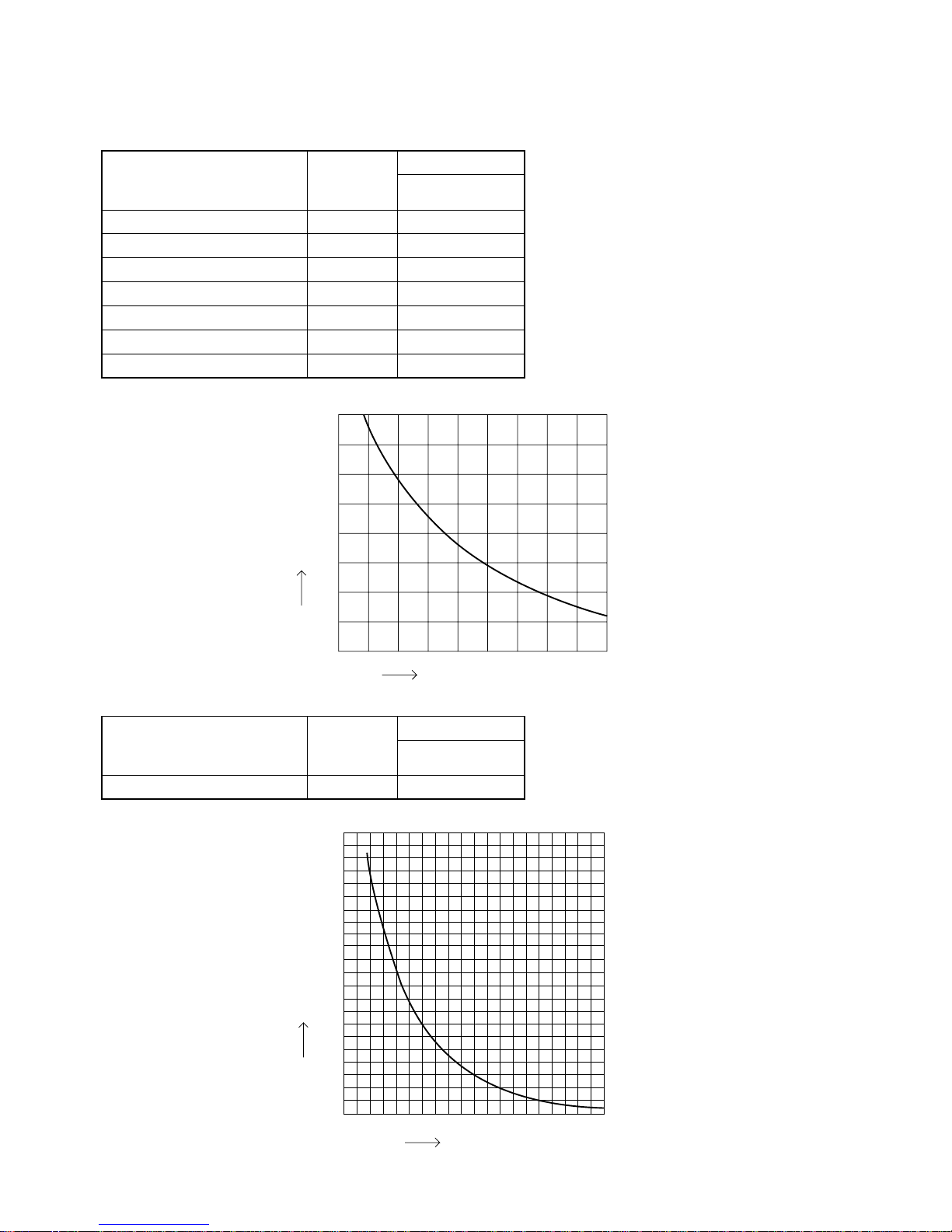
2-3. Other Component Specifications
0
0102030405060708090
40
60
80
100
120
140
160
180
200
20
Resistance (k ohm)
Temperature (°C)
40
35
30
25
20
15
10
5
0
-20-15-
10-50 5101520
Temperature (°C)
Resistance (k ohm)
Outdoor air temp sensor
Outdoor heat exchanger sensor
AW / AN sensor
BW / BN sensor
CW / CN sensor
DW / DN sensor
EW / EN sensor
TKS295B
TKS334B
TKS334B
TKS334B
TKS334B
TKS334B
TKS334B
Model No.
of sensor
Sensor Name
1
1
1/1
1/1
1/1
1/1
1/1
Quantity of Sensor
SAPCMRV3656EH
Compressor temp sensor TKS335B
Model No.
of sensor
Sensor Name
1
Quantity of Sensor
SAPCMRV3656EH
9
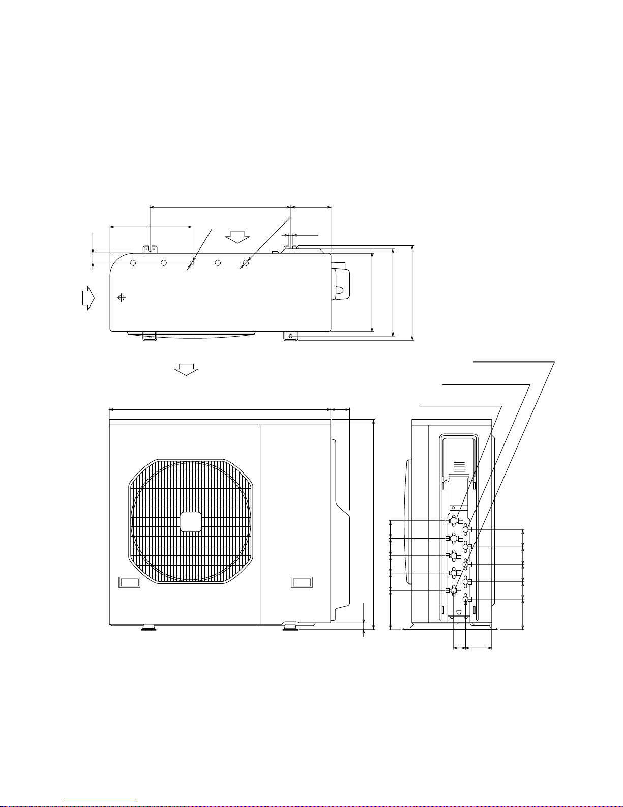
Unit: mm
(852-0-0010-18600-0)
3. DIMENSIONAL DATA
Outdoor Unit SAP-CMRV3656EH
AIR INTAKE
600
ID:18
5-ID:23.6
940 80
51 110
43
341
376
410
347
170
16
AIR DISCHARGE
AIR INTAKE
30
910
168 75 75 75 75
131 75 75 75 75
Wide tube service valve
dia.12.70 (1/2")
× 2
Wide tube service valve
dia.9.52 (3/8")
× 3
Narrow tube service valve
dia.6.35 (1/4")
× 5
10
Outdoor Unit SAP-CMRV3656EH
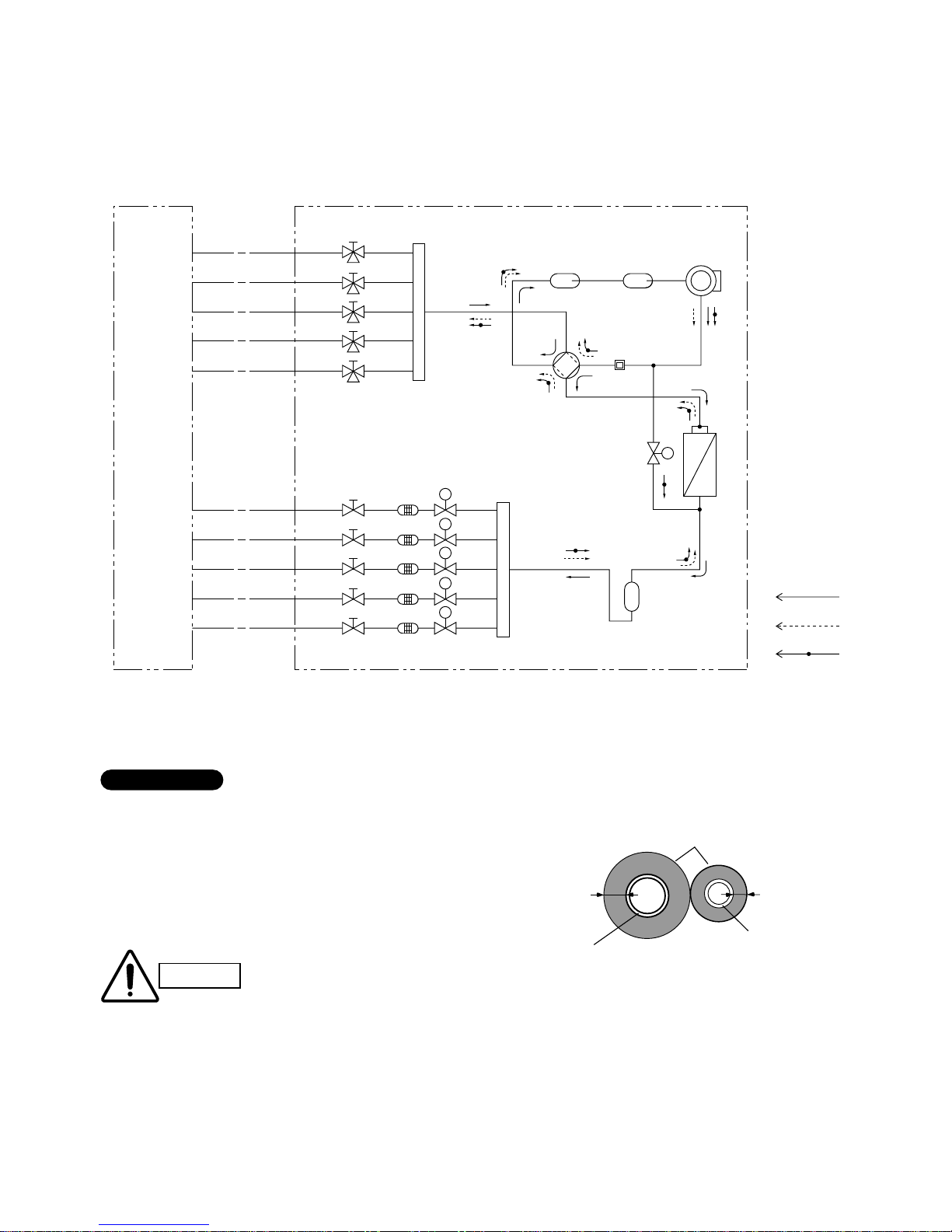
Insulation of Refrigerant Tubing
Because capillary tubing is used in the outdoor unit, both the
wide and narrow tubes of this air conditioner become cold. To
prevent heat loss and wet floors due to dripping of
condensation, both tubes must be well insulated with a
proper insulation material. The thickness of the insulation
should be a min. 8 mm.
After a tube has been insulated,
never try to bend it into a narrow
curve because it can cause the tube
to break or crack.
Wide tube
Thickness:
Min. 8 mm
Insulation
Narrow tube
Thickness:
Min. 8 mm
IMPORTANT
CAUTION
Compressor
4-way
valve
Muffler
Main
accumulator
Sub
accumulator
Service valve on
narrow tube
Service valve on
wide tube
Wide tube
EN
DN
CN
BN
AN
EW
DW
CW
BW
AW
O.D.12.7mm
O.D.12.7mm
O.D.9.52mm
O.D.9.52mm
O.D.9.52mm
Narrow tube
O.D.6.35mm
O.D.6.35mm
O.D.6.35mm
O.D.6.35mm
O.D.6.35mm
Heat exchanger
Cooling cycle
Heating cycle
Defrosting cycle
Indoor unit Outdoor unit
Defrost valve
for hot gas bypass
Receiver tank
Strainer
S
M
M
M
Electric
expansion
valve
Header
Header
M
M
4. REFRIGERANT FLOW DIAGRAM
4-1. Refrigerant Flow Diagram
11
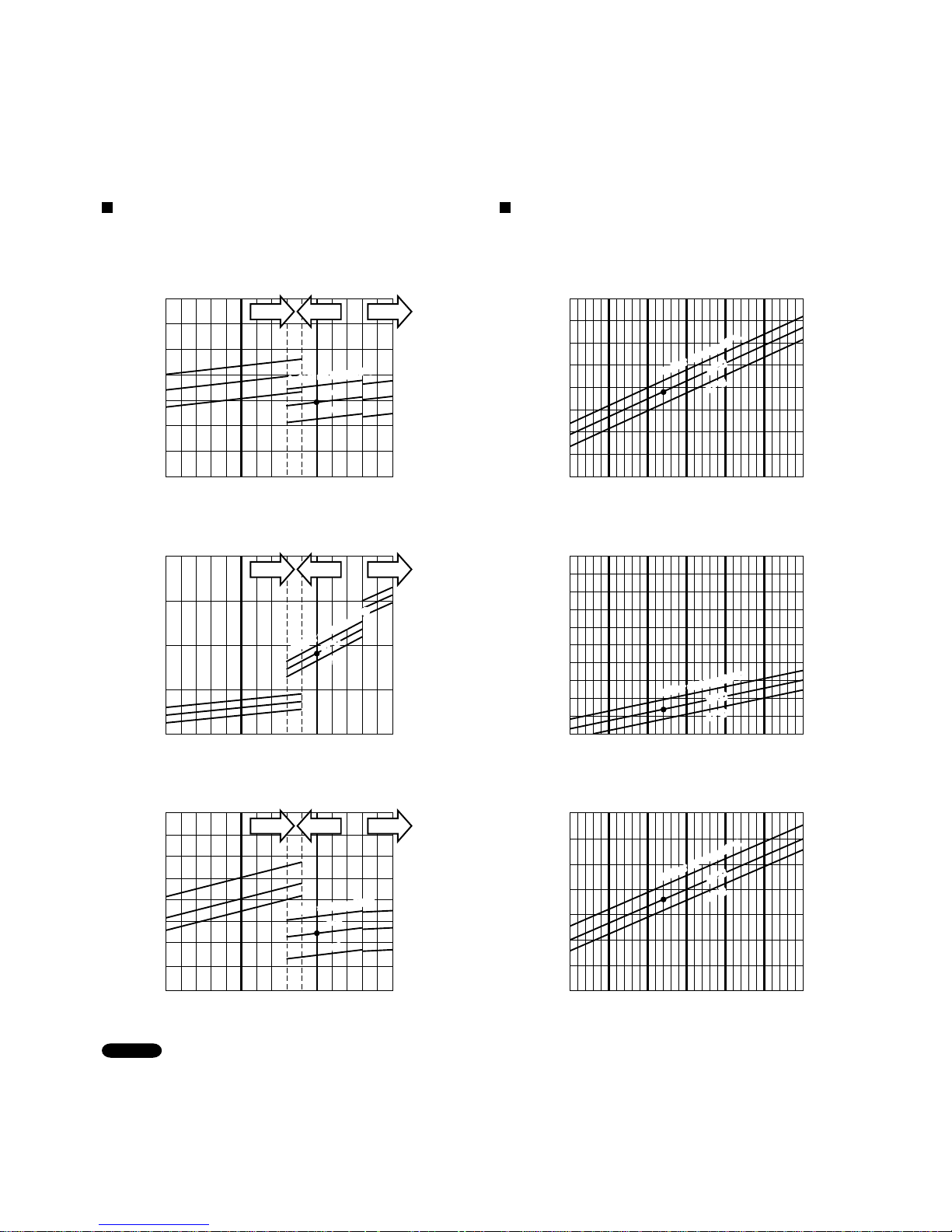
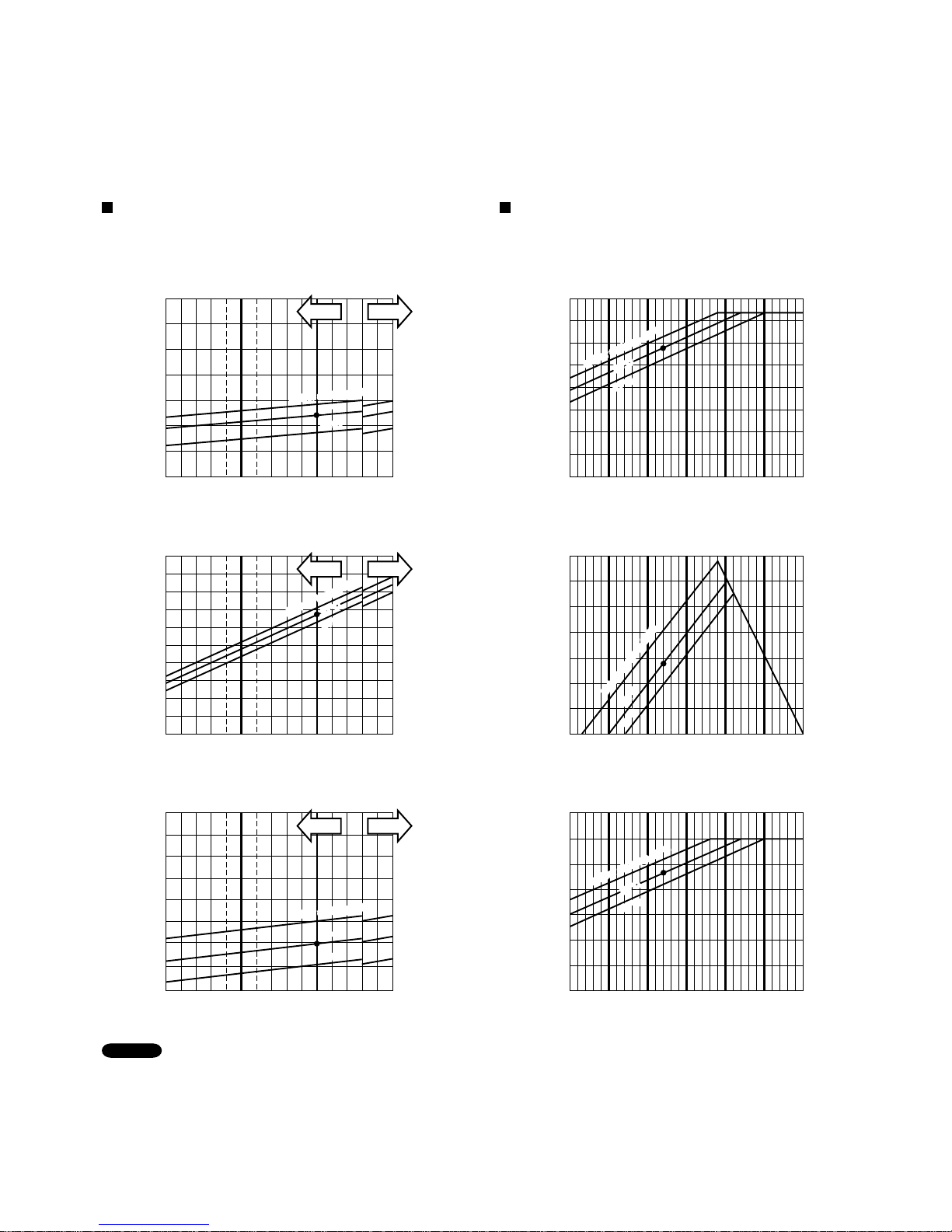
Cooling Characteristics
(RH : 46%, Indoor fan speed : High fan)
(230V, 50Hz)
Heating Characteristics
(RH : 85%, Indoor fan speed : High fan)
(230V, 50Hz)
(1) Low pressure performance chart (1) High pressure performance chart
(2) Operating current performance chart (2) Operating current performance chart
(3) Indoor discharge air performance chart (3) Indoor discharge air performance chart
• This performance chart shows operation of a single wall-mounted indoor unit. The performance chart will vary depending on
the indoor unit type.
• Check each performance value in test-run mode. Electrical performance values represent a combined indoor/outdoor value.
(In this case, be sure to stop all the indoor units where performance is not being checked.)
• The performance is for a tubing length of 7.5 m. If the tubing length is different, the performance chart will vary.
NOTE
Outdoor air temperature (°C) Outdoor air temperature (°C)
30 35 4025
Lo fan Mid fanHi fan
-5 0510 15 20 25
Operating current (A)
Operating current (A)
Outdoor air temperature (°C) Outdoor air temperature (°C)
30 35 40
4
5
3
25
-5 0510 15 20 25
8
9
7
6
5
4
Indoor discharge air temperature (°C)
Indoor discharge air temperature (°C)
Outdoor air temperature (°C) Outdoor air temperature (°C)
5
-5 0510 15 20 25
55
50
45
40
35
30
25
20
20
°
C
17
°
C
Indoor air temp.23
°
C
Indoor air temp.23°C
20°C
17°C
30 35 40
25
20
15
10
25
27
°
C
24
°
C
Indoor air temp.30
°C
Indoor air temp.30°C
27°C
24°C
20°C
17°C
24°C
27
°
C
24
°
C
Indoor air temp.30
°
C
Indoor air temp.30°C
27°C
24°C
20
°
C
17
°
C
Indoor air temp.23
°
C
Indoor air temp.23°C
20°C
17°C
27°C
Indoor air temp.30
°
C
Indoor air temp.30°C
Indoor air temp.23
°
CIndoor air temp.23°C
Low pressure at wide tube service valve
MPaG (kgf/cm
2
G)
High pressure at wide tube service valve
MPaG (kgf/cm
2
G)
1.0
(10.2)
1.2
(12.2)
0.8
(8.2)
0.6
(6.2)
3.5
(35.7)
3.0
(30.6)
2.5
(25.5)
2.0
(20.4)
1.5
(15.3)
5. PERFORMANCE DATA
5-1. Temperature Charts
Outdoor Unit SAP-CMRV3656EH Indoor Unit SAP-KMRV76EH × 1
Lo fan Mid fanHi fan
Lo fan Mid fanHi fan
12
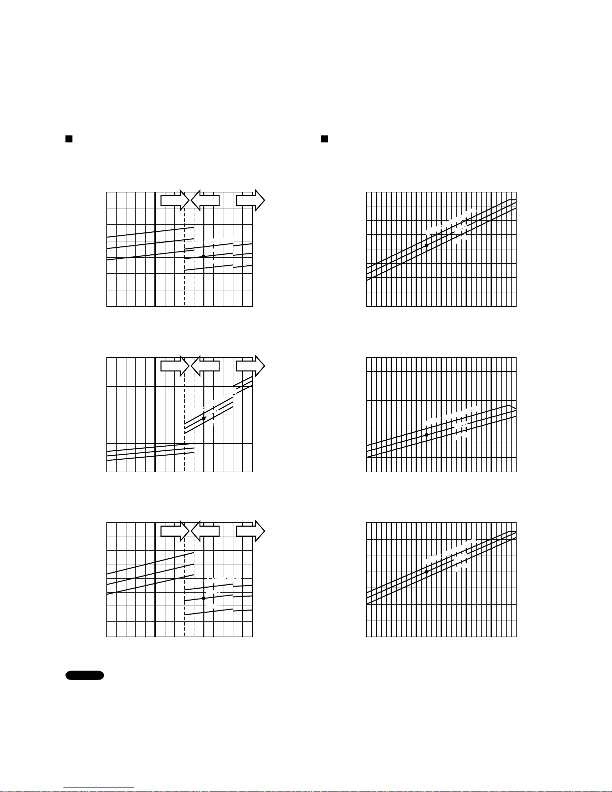
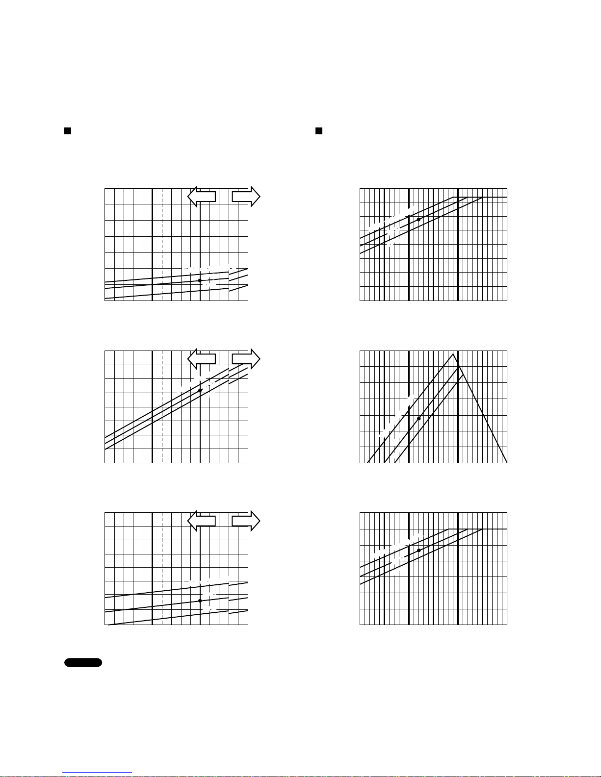
Cooling Characteristics
(RH : 46%, Indoor fan speed : High fan)
(230V, 50Hz)
Heating Characteristics
(RH : 85%, Indoor fan speed : High fan)
(230V, 50Hz)
(1) Low pressure performance chart (1) High pressure performance chart
(2) Operating current performance chart (2) Operating current performance chart
(3) Indoor discharge air performance chart (3) Indoor discharge air performance chart
• This performance chart shows operation of a single wall-mounted indoor unit. The performance chart will vary depending on
the indoor unit type.
• Check each performance value in test-run mode. Electrical performance values represent a combined indoor/outdoor value.
(In this case, be sure to stop all the indoor units where performance is not being checked.)
• The performance is for a tubing length of 7.5 m. If the tubing length is different, the performance chart will vary.
NOTE
Outdoor air temperature (°C) Outdoor air temperature (°C)
30 35 4025
Lo fan Mid fanHi fan
-5 0510 15 20 25
Operating current (A)
Operating current (A)
Outdoor air temperature (°C) Outdoor air temperature (°C)
30 35 40
4
5
3
25
-5 0510 15 20 25
7
8
6
5
4
Indoor discharge air temperature (°C)
Indoor discharge air temperature (°C)
Outdoor air temperature (°C) Outdoor air temperature (°C)
5
-5 0510 15 20 25
55
50
45
40
35
30
25
20
20
°
C
17
°
C
Indoor air temp.23
°
C
Indoor air temp.23°C
20°C
17°C
30 35 40
25
20
15
10
25
27
°
C
24
°
C
Indoor air temp.30
°C
Indoor air temp.30°C
27°C
24°C
Indoor air temp.23
°
C
Indoor air temp.23°
C
20°C
17°C
24°C
27
°
C
24
°
C
Indoor air temp.30
°
C
Indoor air temp.30°C
27°C
24°C
Indoor air tem
p.23
°
C
Indoor air tem
p.23°C
Outdoor Unit SAP-CMRV3656EH Indoor Unit SAP-KMRV96EH × 1 or SAP-KRV96EHDSA × 1
Indoor air temp.30
°
C
Indoor air temp.30°C
27°C
Low pressure at wide tube service valve
MPaG (kgf/cm
2
G)
High pressure at wide tube service valve
MPaG (kgf/cm
2
G)
1.0
(10.2)
1.2
(12.2)
0.8
(8.2)
0.6
(6.2)
3.5
(35.7)
3.0
(30.6)
2.5
(25.5)
2.0
(20.4)
1.5
(15.3)
Lo fan Mid fanHi fan
Lo fan Mid fanHi fan
17
°
C
17°C
20°C20°C
13
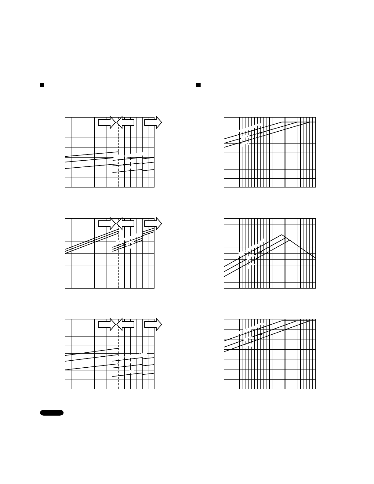
Cooling Characteristics
(RH : 46%, Indoor fan speed : High fan)
(230V, 50Hz)
Heating Characteristics
(RH : 85%, Indoor fan speed : High fan)
(230V, 50Hz)
(1) Low pressure performance chart (1) High pressure performance chart
(2) Operating current performance chart (2) Operating current performance chart
(3) Indoor discharge air performance chart (3) Indoor discharge air performance chart
• This performance chart shows operation of a single wall-mounted indoor unit. The performance chart will vary depending on
the indoor unit type.
• Check each performance value in test-run mode. Electrical performance values represent a combined indoor/outdoor value.
(In this case, be sure to stop all the indoor units where performance is not being checked.)
• The performance is for a tubing length of 7.5 m. If the tubing length is different, the performance chart will vary.
NOTE
Outdoor air temperature (°C) Outdoor air temperature (°C)
30 35 4025
-5 0510 15 20 25
Operating current (A)
Operating current (A)
Outdoor air temperature (°C) Outdoor air temperature (°C)
30 35 40
4
5
6
3
25
-5 0510 15 20 25
12
13
10
11
9
8
7
Indoor discharge air temperature (°C)
Indoor discharge air temperature (°C)
Outdoor air temperature (°C) Outdoor air temperature (°C)
5
-5 0510 15 20 25
55
50
45
40
35
30
25
20
20
°
C
17
°C
Indoor air temp.23
°
C
Indoor air temp.23°C
20°C
17°C
30 35 40
25
20
15
10
25
27
°
C
24
°
C
27°C
24°C
Indoor air temp.23
°
C
Indoor air temp.23°C
20°C
17°C
24°C
27
°
C
24
°
C
Indoor air temp.30
°
C
Indoor air temp.30°C
27°C
24°C
Indoor air temp.23
°
C
Indoor air temp.23°C
Outdoor Unit SAP-CMRV3656EH
Indoor air temp.30
°
C
Indoor air temp.30°C
27°C
Low pressure at wide tube service valve
MPaG (kgf/cm
2
G)
High pressure at wide tube service valve
MPaG (kgf/cm
2
G)
1.0
(10.2)
1.2
(12.2)
0.8
(8.2)
0.6
(6.2)
3.5
(35.7)
3.0
(30.6)
2.5
(25.5)
2.0
(20.4)
1.5
(15.3)
Lo fan Mid fanHi fan
Lo fan Mid fanHi fan
Lo fan Mid fanHi fan
Indoor air temp.30
°C
Indoor air temp.30°C
17
°
C
17°C
20°C20°C
Indoor Unit SAP-KMRV126EH × 1 or SAP-KRV126EHDS × 1
14
30 35 4025
Cooling Characteristics
(RH : 46%, Indoor fan speed : High fan)
(230V, 50Hz)
Heating Characteristics
(RH : 85%, Indoor fan speed : High fan)
(230V, 50Hz)
(1) Low pressure performance chart
(2) Operating current performance chart
(3) Indoor discharge air performance chart
• This performance chart shows operation of a single wall-mounted indoor unit. The performance chart will vary depending on
the indoor unit type.
• Check each performance value in test-run mode. Electrical performance values represent a combined indoor/outdoor value.
(In this case, be sure to stop all the indoor units where performance is not being checked.)
• The performance is for a tubing length of 7.5 m. If the tubing length is different, the performance chart will vary.
NOTE
Outdoor air temperature (°C)
Mid fanHi fan
Operating current (A)
Outdoor air temperature (°C)
30 35 40
6
5
7
8
9
4
25
Indoor discharge air temperature (°C)
Outdoor air temperature (°C)
5
30 35 40
25
20
15
10
25
27
°
C
24
°
C
Indoor air tem
p.30
°C
Indoor air tem
p.30°C
27°C
24°C
24°C
27
°
C
24
°
C
Indoor air te
mp.30
°
C
Indoor air te
mp.30°C
27°C
24°C
Outdoor Unit SAP-CMRV3656EH Indoor Unit SAP-KRV186EH × 1
Mid fanHi fan
Indoor air temp.30
°
C
Indoor air temp.30°C
Mid fanHi fan
27°C
Low pressure at wide tube service valve
MPaG (kgf/cm
2
G)
1.0
(10.2)
1.2
(12.2)
0.8
(8.2)
0.6
(6.2)
-5 0510 15 20 25
60
55
50
45
40
35
30
25
Indoor air temp.23
°
C
Indoor air temp.23°C
(1) High pressure performance chart
(2) Operating current performance chart
(3) Indoor discharge air performance chart
Outdoor air temperature (°C)
-5 0510 15 20 25
Operating current (A)
Outdoor air temperature (°C)
-5 0510 15 20 25
14
12
13
15
Indoor discharge air temperature (°C)
Outdoor air temperature (°C)
20
°C
17
°
C
20°C
17°C
Indoor air temp.23
°
C
Indoor air temp.23°C
20°C
17°C
High pressure at wide tube service valve
MPaG (kgf/cm
2
G)
3.5
(35.7)
3.0
(30.6)
2.5
(25.5)
2.0
(20.4)
1.5
(15.3)
20
°
C
17
°
C
Indoor air temp.23
°
C
Indoor air temp.23°C
20°C
17°C
15
-5 0510 15 20 25
60
55
50
45
40
35
30
25
Indoor air temp.23
°
C
Indoor air temp.23°C
30 35 4025
Cooling Characteristics
(RH : 46%, Indoor fan speed : High fan)
(230V, 50Hz)
Heating Characteristics
(RH : 85%, Indoor fan speed : High fan)
(230V, 50Hz)
(1) Low pressure performance chart (1) High pressure performance chart
(2) Operating current performance chart (2) Operating current performance chart
(3) Indoor discharge air performance chart (3) Indoor discharge air performance chart
• This performance chart shows operation of a single wall-mounted indoor unit. The performance chart will vary depending on
the indoor unit type.
• Check each performance value in test-run mode. Electrical performance values represent a combined indoor/outdoor value.
(In this case, be sure to stop all the indoor units where performance is not being checked.)
• The performance is for a tubing length of 7.5 m. If the tubing length is different, the performance chart will vary.
NOTE
Outdoor air temperature (°C) Outdoor air temperature (°C)
Mid fanHi fan
-5 0510 15 20 25
Operating current (A)
Outdoor air temperature (°C)
30 35 40
9
8
10
11
12
25
Indoor discharge air temperature (°C)
Indoor discharge air temperature (°C)
Outdoor air temperature (°C) Outdoor air temperature (°C)
5
20
°C
17
°
C
20°C
17°C
30 35 40
25
20
15
10
25
27
°
C
24
°
C
Indoor air temp.30
°C
Indoor air temp.30°C
27°C
24°C
Indoor air temp.23
°
C
Indoor air temp.23°C
20°C
17°C
27
°
C
24
°
C
Indoor air tem
p.30
°
C
Indoor air tem
p.30°C
27°C
24°C
Outdoor Unit SAP-CMRV3656EH Indoor Unit SAP-KRV246EH × 1
Mid fanHi fan
Indoor air temp.30
°
C
Indoor air temp.30°C
Mid fanHi fan
24°C
27°C
Low pressure at wide tube service valve
MPaG (kgf/cm
2
G)
High pressure at wide tube service valve
MPaG (kgf/cm
2
G)
1.0
(10.2)
1.2
(12.2)
0.8
(8.2)
0.6
(6.2)
3.5
(35.7)
3.0
(30.6)
2.5
(25.5)
2.0
(20.4)
1.5
(15.3)
Operating current (A)
Outdoor air temperature (°C)
-5 0510 15 20 25
14
12
13
15
20
°
C
17
°
C
Indoor air temp.23°
C
Indoor air temp.23°C
20°C
17°C
16
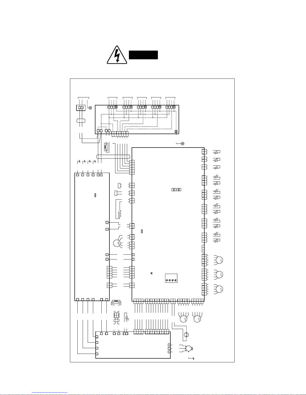
WARNING
To avoid electrical shock hazard, be sure to
disconnect power before checking, servicing
and/or cleaning any electrical parts.
6. ELECTRICAL DATA
6-1. Electric Wiring Diagrams
Outdoor Unit SAP-CMRV3656EH
8FA2-5250-52600-3
BLK
1 1
2
123
4
123
4
123
4
123
4
567
8
567
8
9
10
4132110987654321
9
10
4
1
2
2
1
1
2
2
3
3
4
4
5
1 2 1 2 3 4 551 2 1 2 3
1 2 3
1 2 3
1 3
1 3
1 3
1 34 5
321109
1
2
1
2
1
2
1
2
3
4
3
4
55
8765432
1
2
+++
+
HIC- E
E1E2E3
HIC+
DC+
DC-
HIC- HIC+ DC+ DC-
BD2
+
+ + + +
w
w w
BD1
wL1w
L2
TH01
CN13
HIC-2
(WHT)
CN07
HIC-2
(WHT)
CN23
CT
(BRN)
POWER LED
ERROR MONITOR
F02
3.15A/400V
(T3.15 AL400V)
ERR0
ERR1
ERR2
ERR2
CN06
A-B
(WHT)
DC- DC+ CN31
FM2
(RED)
FAN MOTOR
CRANKCASE
HEATER
DEFROST VALVE
COIL
4WAY VALVE
COIL
TERMINAL PLATE
TERMINAL (2P)
REACTOR
CN11
SI
(WHT)
CN30
FM1
(RED)
CN12
ACIN
(BLU)
CN08
HIC-1
(WHT)
CN16
OLR
(WHT)
CN05
MV-E
(YEL)
CN04
MV-D
(BLU)
(RED)
CN03
MV-C
(BLK)
CN02
MV-B
(WHT)
CN01
MV-A
(WHT)
CN17
T-RUN/TEST
(YEL)
CN28
TH-E
(BLU)
CN27
TH-D
(RED)
CN26
TH-C
(BLK)
CN25
TH-B
(WHT)
CN24
TH-A
(WHT)
CN22
COMP
(YEL)
CN21
GAIKI
(BLK)
CN20
COIL
CN12
HIC-1
(WHT)
W
T
R
S
V U
HIC BOARD
CONTROL P.C.BOARD
ON
SW02
1 2
NOISE FILTER P.C.BOARD
w
w
+ + +
1
2
+
+ +
B02
(BRN)
CN02
CT
(WHT)
CN03
A-B
DCOUT- DCOUT+
w w
OUT1 OUT2
B01
REACTOR
FIN TEMPERATURE
THERMISTOR
FERRITE
CORE
MAGNETIC COIL
COMPRESSOR
MOTOR
OVERLOAD RELAY
(OLR)
M
MS
3~
BLU
BRN
YEL
GRY
WHT
BLK
WHT
WHT
WHT
WHT
t˚
BLK
BLK
BLK
BLK
BLK
BLK
BLK
BLK
BLK
BLK
BLK
BLK
BLK
BLK
BLK
BLK
WHT
WHT
BLK
BLK
BLK
BLK
BLK
BLK
RED
WHT
WHT
ORG
RED
YEL
BLK
GRY
1
2
1
1
1
2
2
3
3
4
4
5
5
2
3
4
3
4
55
MAGNETIC COIL
MAGNETIC
COIL
MAGNETIC
COIL
MAGNETIC
COIL
E-W THERMISTOR
E-N THERMISTOR
M
M
ORG
RED
YEL
BLK
GRY
WHT
RED
BLU
GRN
ORG
RED
YEL
BLK
GRY
1
1
2
2
3
3
4
4
5
5
M
ORG
RED
YEL
BLK
GRY
1
1
2
2
3 1 2 3
3
4
4
1
1
2
2
3
3
4
4
5
5
M
ORG
RED
YEL
BLK
GRY
M
BRN
WHT
ORG
RED
BLU
t˚
t˚
YEL
YEL
YEL
YEL
D-W THERMISTOR
D-N THERMISTOR
1
1
2
2
3
3
4
4
t˚
t˚
YEL
YEL
YEL
YEL
C-W THERMISTOR
C-N THERMISTOR
1
1
2
2
3
3
4
4
t˚
t˚
YEL
YEL
YEL
YEL
B-W THERMISTOR
B-N THERMISTOR
1
1
2
2
3
3
4
4
t˚
t˚
YEL
YEL
YEL
YEL
A-W THERMISTOR
A-N THERMISTOR
COMPRESSOR
THERMISTOR
OUTDOOR
THERMISTOR
COIL
THERMISTOR
1
1
2
2
3
3
4
4
t˚
t˚
YEL
YEL
1
1
2
2
t˚
BLK
BLK
1
1
2
2
t˚
BLK
BLK
1
1
2
2
11223344556677
t˚
YEL
YEL
YEL
YEL
1 3
1 3
CN13
HEATER
(ORG)
1 3
1 3
CN14SV(BLK)
1 3
1 3
CN15
RV
(WHT)
6 5
6 5
4 3
4 3
2 1
2 1
BLK
WHT
BRN
BRN
BLU
BLU
BLU
BLU
F01
25A/250V
(T25 AL250V)
GRNwGRNwGRN
w
ACIN1wACIN2 w
L
N
L
N
L1
L2
123
GRN
BLK
WHT
BLK
123
123
123
123
POWER
SUPPLY
1-230V 50Hz
TO INDOOR
UNIT No.E
CONNECTING
TO INDOOR
UNIT No.D
CONNECTING
TO INDOOR
UNIT No.C
CONNECTING
TO INDOOR
UNIT No.B
CONNECTING
TO INDOOR
UNIT No.A
CONNECTING
WHT
ORG
GRY
BRN
BLU
RED
GRN/YEL
ON
SW01
1 2
BLK
WHT
FERRITE
CORE
FERRITE
CORE
17
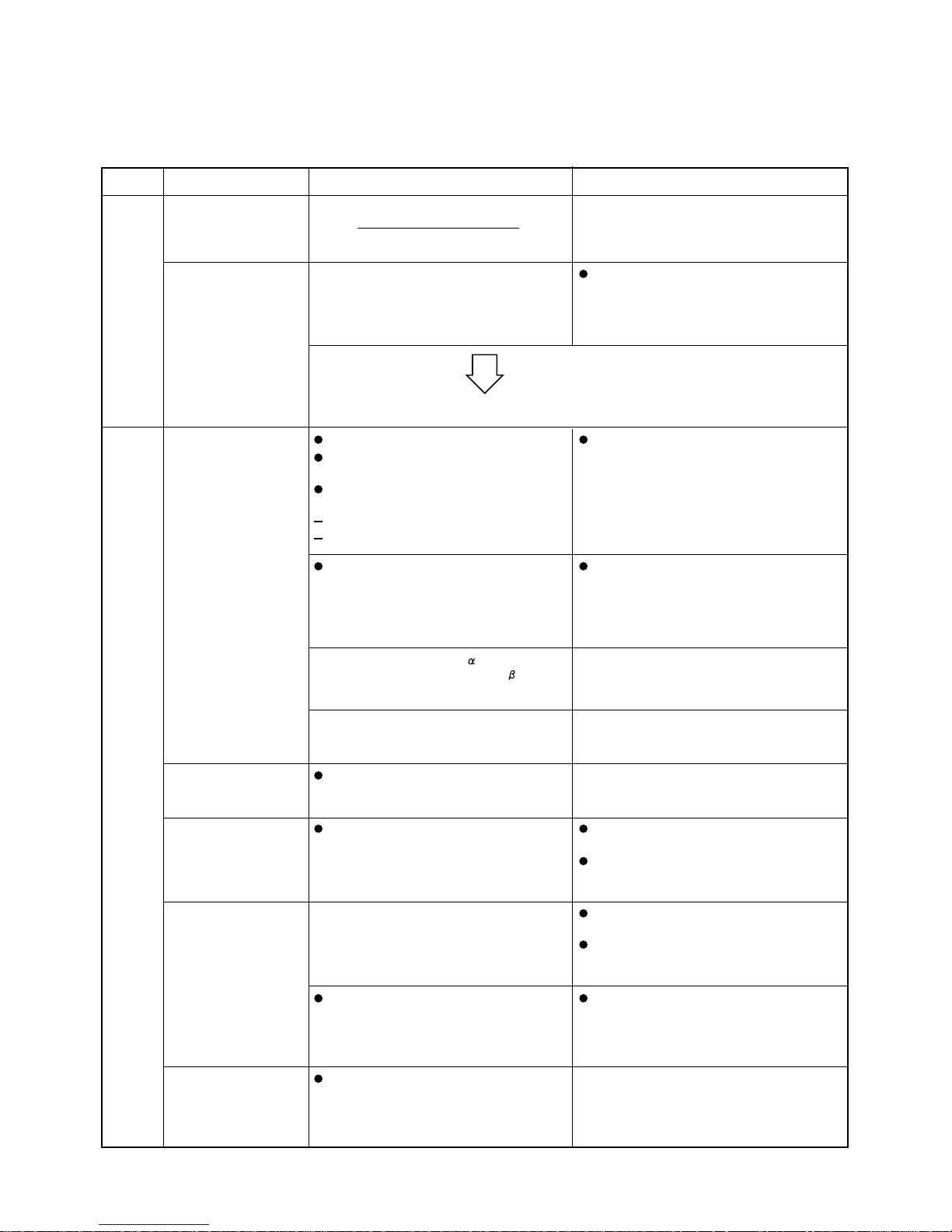
7. FUNCTIONS
7-1. Explanation of Functions
Control/conditions
INITIAL
Breaker is ON. Power is supplied to the indoor and outdoor unit
control circuits, however the unit remains stopped.
Positioning of the outdoor unit electric expansion
valve is performed.
The ON/OFF operation
button on the remote
controller is pressed.
If automatic operation mode has been selected
with the remote controller, operation begins in
HEAT, SENSOR DRY, or COOL mode
depending on the room temperature and
outdoor temperature at the time operation starts.
Depending on the operational mode, refer to the HEAT, SENSOR DRY, or COOL item.
This applies in the case of automatic
HEAT/COOL operation.
HEAT
Unit operation Explanation
The ON/OFF operation
button on the remote
controller is pressed.
The unit is forced to stop for 5 minutes after
the power is turned ON, or 5 minutes after the
compressor stops, in order to protect the
compressor.
The frequency is increased at the rate of 1 Hz
every 0.5 seconds.
Operation lamp illuminates.
Indoor fan is stopped to prevent cold air from
being emitted.
Outdoor unit begins operating after
forced-stop is canceled.
the compressor starts.
the outdoor fan starts.
This is in order to stabilize the return of oil to the
compressor.
When the frequency reaches Hz,frequency
increases are stopped for a period of seconds.
(Refor to Table 2 "Freguency control".)
If the indoor and outdoor temperatures are high,
the current peak cut-off activates, stopping any
increases in frequency.
The frequency then increases.
The thermostat turns
OFF.
The outdoor unit stops. (It does not stop if the
thermostat for another indoor unit is ON.)
Approximately 30 seconds after the
thermostat turns OFF, the indoor fan is
stopped.
The indoor fan is stopped.
The indoor and outdoor
temperatures are high.
The outdoor unit starts automatically after 5
minutes.
During these 5 minutes, a low-pressure
pressure balance is achieved, allowing the
compressor to start more easily.
In order to protect the compressor, the outdoor
unit will not operate for 5 minutes after the
thermostat turns OFF, even if the room
temperature drops below the desired
temperature.
The room temperature
has reached the desired
temperature.
Operating frequency is stabilized in order to
maintain a comfortable environment.
The indoor temperature and the remote
controller temperature setting are
approximately equal.
The thermostat turns ON. The unit operated before, and the temperature of
the indoor heat exchanger is relatively warm.
Therefore,the fan speed may start at the set fan
speed at the same time that the thermostat turns
ON.
The indoor fan is started.
Depending on the relationship between the
remote controller temperature setting and the
room temperature, the compressor may stop
temporarily (in other words, the thermostat
may turn OFF).
When the indoor coil temperature rises,
the indoor fan changes from "LL"
to the set fan speed.
The amount of heat pump exceeds the amount
of heat radiation from the room.
Therefore, there is no need to further increase
the compressor capacity, and the frequency is
stabilized or lowered.
The frequency is not increased, even if
there is a difference between the room
temperature and the desired temperature.
In some cases, the frequency may be
decreased.
18
Control/conditions
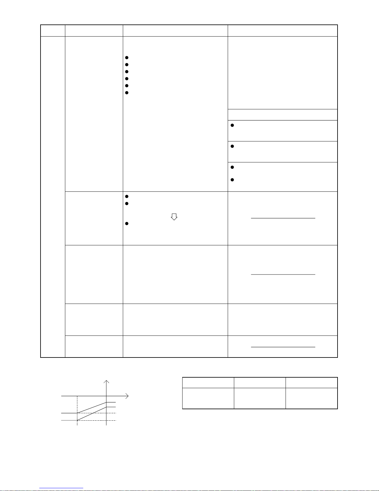
HEAT
When defrost operation
begins, frost has formed
on the outdoor unit
(when the ambient air
temperature is low).
Defrost operation begins based on outdoor heat
exchanger temperature and outdoor air
temperature conditions.
Non-stop defrost (Refer to Fig. 1)
1. After HEAT operation begins, the temperature
of the outdoor heat exchanger is at or below the
L1 line for 48 minutes.
(If outdoor air temperature is less than –3 °C,
the time is 48 minutes)
2. After HEAT operation begins, the temperature
of the outdoor heat exchanger is at or below the
L2 line for 120 minutes.
The 4-way valve remains ON during defrost.
Non-stop defrost
Unit operation Explanation
The outdoor fan stops and the solenoid
valve turns ON, allowing the refrigerant to
bypass the indoor unit.
Indoor fan : Stopped
Outdoor fan : Stopped
Compressor : 70 Hz
Solenoid valve (for hot gas bypass): ON
4-way valve : Remains ON
Operation lamp : Red and orange ON
alternately
Defrost release Indoor fan turns ON.
After 10 seconds, the solenoid valve
(for hot gas bypass) turns OFF.
When the cold air feel has disappeared,
the indoor fan starts and gradually increases
speed until it reaches the set speed.
STOP
[Clean defrost]
Defrost is performed
when the outdoor unit is
stopped, and the
temperature of the
outdoor unit coil is at or
below the L1 line.
(Refer to Fig. 1.)
All indicator lamps turn OFF. The indoor and
outdoor units stop.
The operating frequency during defrost is
70 Hz. (Frequency is lowered if the current
peak cut-off function is activated.)
The maximum length of a single defrost
operation is 12 minutes.
For the outdoor heat exchanger temperature
conditions for ending defrost, refer to Table 1.
Operation is restarted
within 4 hours (only when
AUTO mode is selected
with the remote
controller).
Within 4 hours after operation was stopped, it is
assumed that there has been no significant
change in the indoor and outdoor temperatures,
and the previous conditions (HEAT) are stored.
Table 1
Starts operating in the same operating mode
(HEAT) and with the same temperature
settings as before operation was stopped.
Operation starts after 4
hours or more have
passed.
Outdoor heat
exchanger temperature
Fig. 1
Outdoor air
temperature
(–20) 0
(– 6)
(– 7)
(– 16)
(– 25)
L2
L1
New operation begins based on the
temperature conditions at the time the
ON/OFF button is pressed.
Temperature of releasing
*1 The temperature for releasing of defrosting is (20 °C) or higher when the
outdoor air temperature is less than 0 °C.
Defrost operation time
Heat exchanger
temperature for
releasing defrosting
Less than 2 minutes 2 minutes or more
No releasing 14 °C or higher (*1)
19
Control/conditions
COOL
The ON/OFF operation
button on the remote
controller is pressed.
The room temperature
has reached the
desired temperature.
The outdoor unit does not operate for 5 minutes
even after the breaker is turned ON.
This is in order to stabilize the return of oil to the
compressor.
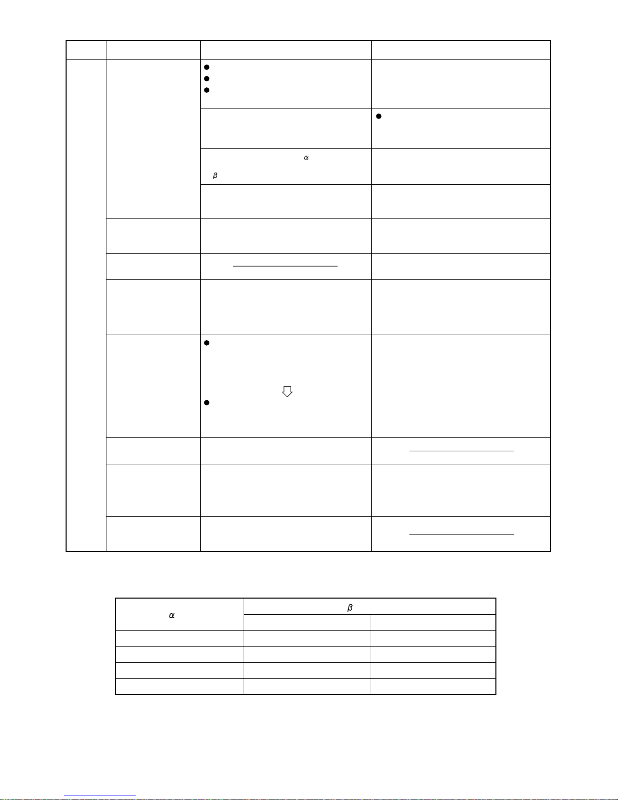
Frequency control
(Hz)
(26) Hz
(35) Hz
(45) Hz
(55) Hz
The outdoor unit starts.
(Compressor and the outdoor fan start.)
When the frequency reaches Hz,
frequency increases are stopped for a period
of seconds. (Refer to Table 2.)
If the indoor and outdoor temperatures are high,
the current peak cut-off activates, stopping
any increases in frequency.
The frequency then increases.
Operating frequency is stabilized in order to
maintain a comfortable environment.
The indoor temperature and the desired
temperature are approximately equal.
The thermostat turns
ON again.
After 5 minutes, the outdoor unit begins operating
automatically.
During these 5 minutes, a pressure balance is
achieved, allowing the compressor to start
more easily.
After the thermostat turns ON again, the
outdoor unit will not operate for 5 minutes,
even if the room temperature increases
above the desired temperature.
Operation is restarted
within 4 hours (only when
AUTO mode is selected
with the remote
controller).
Within 4 hours after operation was stopped, it is
assumed that there has been no significant
change in the indoor and outdoor temperatures,
and the previous conditions (COOL) are stored.
Starts operating in the same operating mode
(COOL) and with the same temperature
settings as before operation was stopped.
Operation starts after 4
hours or more have
passed.
New operating mode is determined based on
the temperature conditions at the time the
ON/OFF operation button is pressed.
Stop All indicator lamps turn OFF. The indoor and
outdoor units stop.
Freeze prevention In order to protect against freezing, the
compressor stops temporarily, until the
temperature of the indoor heat exchanger has
risen.
The thermostat turns
OFF.
The outdoor unit stops. (It does not stop if the
thermostart for another indoor unit is ON.)
Unit operation Explanation
The operation lamp illuminates.
The indoor fan operates at the set fan speed.
The outdoor unit stops.
When the temperature of the indoor heat
exchanger drops to approximately 2 °C
or below, the compressor turns OFF, the
outdoor fan turns OFF, and the indoor fan
continues operating with no changes.
Approximately 5 minutes later, if the
temperature of the indoor heat exchanger
is adove 8 °C, the system returns to its
original conditions.
The frequency is increased at the rate of 0.5
Hz every 1 seconds.
Outdoor air temperature is below 0 °C.
(120) seconds
(60) seconds
(60) seconds
(180) seconds
Table 2
(senconds)
Outdoor air temperature is 0 °C or higher.
(60) seconds
(30) seconds
(30) seconds
(90) seconds
20
Control/conditions
SENSOR
DRY
(1/f fluctuation fan)
The ON/OFF operation
button on the remote
controller is pressed.
The outdoor unit does not operate for 5 minutes
even after the breaker is turned ON.
This is in order to stabilize the return of oil to the
compressor.
The outdoor unit starts.
(Compressor and the outdoor fan start.)
When the frequency reaches Hz,
frequency increases are stopped for a period
of seconds. (Refer to Table 2.)
DRY B operation
If the indoor and outdoor temperatures are high,
the current peak cut-off activates, stopping
any increases in frequency.
The frequency then increases.
Unit operation Explanation
The operation lamp illuminates.
The indoor fan operates at the set fan speed.
The outdoor unit stops.
The room temperature
reaches the desired
temperature, and there
is no need for further
cooling.
Operating frequency is stabilized in order to
maintain a comfortable environment.
The room temperature is
15 °C or higher, and is
slightly too cold.
The compressor operates on a 3-minutes ON,
6-minutes OFF cycle, to prevent the room
temperature from dropping too much.
DRY operation starts
DRY A operation
The room temperature is
below 15 °C.
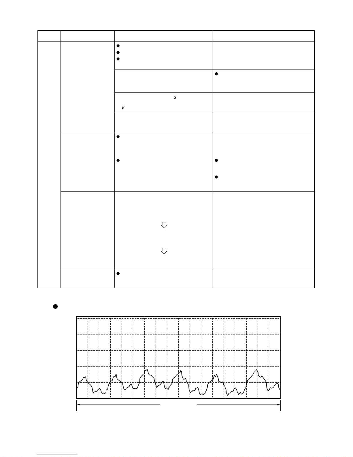
1/f fluctuation fan
250
200
6-minute cycle
Fig. 2
150
100
(Step)
50
0
When monitoring operation begins, the
compressor stops, and the indoor fan operates at
"LL" (very low) speed.
Monitoring operation begins.
The indoor fan changes between "Low"
and "LL" (very low) over a 6-minute cycle.
This is 1/f fluctuation fan operation.
(Refer to Fig. 2.)
The indoor fan changes between "Low"
and "LL" (very low) over a 6-minute cycle.
This is 1/f fluctuation fan operation.
After appoximately 3 minutes, the
compressor turns OFF, the outdoor fan
turns OFF, and the indoor fan turns OFF.
After approximately 6 minutes, the
conditions return to (1).
(1)
(2)
(3)
The frequency is increased at the rate of 0.5
Hz every 1 seconds.
Operates to effectively dehumidify the air while
not excessively reducing the indoor
temperature.
The indoor unit operates at 1/f fluctuation fan
operation, at a fan speed that does not cause
a chilly feeling.
21
 Loading...