

Sanyo SAP-CMRV3143GJ Technical & Service Manual
TECHNICAL & SERVICE MANUAL
OUTDOOR UNIT: SAP-CMRV3143GJ
DC INVERTER MULTI-SYSTEM AIR CONDITIONER
SAP-CMRV3143GJ
Destination: General area (50Hz)
Europe (50Hz)
Australia (50Hz)
General area (60Hz)
Indoor Model No. Product Code No.
SAP-CMRV3143GJ-C 1 852 084 47
REVISION NO. SM700544-01
IMPORTANT
These air conditioners employ new
refrigerant R410A.
Pay special attention when
servicing the unit.
4-room multi Outdoor unit
< Combined Indoor Units >
1. How these units may be combined is given in
the Unit Combination Tables in the Appendix.
2. Be sure to operate the air conditioning
system only when 2 or more indoor units
have been installed. If operated with only a
single unit installed, the returning fluid to the
compressor may cause a malfunction.
NOTE
●Concealed duct type
SAP-DMRV93GJ
SAP-DMRV123GJ
SAP-DMRV183GJ
SAP-DMRV243GJ
●Wall mounted type
SAP-KMRV93GJ
SAP-KMRV123GJ
SAP-KMRV183GJ
SAP-KMRV243GJ
Capacity
9.0 kW
W
Revised Edition
NOV.2003
i
Important!
Please Read Before Starting
This air conditioning system meets strict safety and
operating standards. As the installer or service person,
it is an important part of your job to install or service the
system so it operates safely and efficiently.
For safe installation and trouble-free operation, you
must:
●Carefully read this instruction booklet before
beginning.
●Follow each installation or repair step exactly as
shown.
●Observe all local, state, and national electrical codes.
●Pay close attention to all warning and caution notices
given in this manual.
This symbol refers to a hazard or
unsafe practice which can result
in severe personal injury or
death.
This symbol refers to a hazard or
unsafe practice which can result
in personal injury or product or
property damage.
If Necessary, Get Help
These instructions are all you need for most installation
sites and maintenance conditions. If you require help
for a special problem, contact our sales/service outlet
or your certified dealer for additional instructions.
In Case of Improper Installation
The manufacturer shall in no way be responsible for
improper installation or maintenance service, including
failure to follow the instructions in this document.
Special Precautions
When Wiring
ELECTRICAL SHOCK CAN CAUSE
SEVERE PERSONAL INJURY OR
DEATH. ONLY A QUALIFIED,
EXPERIENCED ELECTRICIAN SHOULD
ATTEMPT TO WIRE THIS SYSTEM.
• Do not supply power to the unit until all wiring and
tubing are completed or reconnected and checked.
• Highly dangerous electrical voltages are used in this
system. Carefully refer to the wiring diagram and
these instructions when wiring. Improper connections
and inadequate grounding can cause accidental
injury or death.
• Ground the unit following local electrical codes.
• Connect all wiring tightly. Loose wiring may cause
overheating at connection points and a possible fire
hazard.
WARNING
CAUTION
WARNING
When Transporting
Be careful when picking up and moving the indoor and
outdoor units. Get a partner to help, and bend your
knees when lifting to reduce strain on your back. Sharp
edges or thin aluminum fins on the air conditioner can
cut your fingers.
When Installing…
…In a Ceiling or Wall
Make sure the ceiling/wall is strong enough to hold the
unit’s weight. It may be necessary to construct a strong
wood or metal frame to provide added support.
…In a Room
Properly insulate any tubing run inside a room to
prevent “sweating” that can cause dripping and water
damage to walls and floors.
…In Moist or Uneven Locations
Use a raised concrete pad or concrete blocks to
provide a solid, level foundation for the outdoor unit.
This prevents water damage and abnormal vibration.
…In an Area with High Winds
Securely anchor the outdoor unit down with bolts and a
metal frame. Provide a suitable air baffle.
…In a Snowy Area (for Heat Pump-type Systems)
Install the outdoor unit on a raised platform that is
higher than drifting snow. Provide snow vents.
When Connecting Refrigerant Tubing
• Use the flare method for connecting tubing.
• Apply refrigerant lubricant to the matching surfaces
of the flare and union tubes before connecting them,
then tighten the nut with a torque wrench for a leakfree connection.
• Check carefully for leaks before starting the test run.
When Servicing
• Turn the power off at the main power box (mains)
before opening the unit to check or repair electrical
parts and wiring.
• Keep your fingers and clothing away from any
moving parts.
• Clean up the site after you finish, remembering to
check that no metal scraps or bits of wiring have
been left inside the unit being serviced.
Others
• Ventilate any enclosed areas when installing or
testing the refrigeration system. Escaped refrigerant
gas, on contact with fire or heat, can produce
dangerously toxic gas.
• Confirm upon completing installation that no
refrigerant gas is leaking. If escaped gas comes in
contact with a stove, gas water heater, electric room
heater or other heat source, it can produce
dangerously toxic gas.
• Do not install only on a single indoor unit.
CAUTION

Table of Contents
Page
1. OPERATING RANGE ............................................................................................................................... 1
2. SPECIFICATIONS
2-1. Unit Specifications.......................................................................................................................... 2
2-2. Major Component Specifications.................................................................................................... 3
2-3. Other Component Specifications.................................................................................................... 4
3. DIMENSIONAL DATA............................................................................................................................... 5
4. REFRIGERANT FLOW DIAGRAM .......................................................................................................... 6
5. PERFORMANCE DATA
5-1. Performance Charts ...................................................................................................................... 7
6. ELECTRICAL DATA
6-1. Electric Wiring Diagram.................................................................................................................. 9
7. INSTALLATION INSTRUCTIONS
7-1. Indoor Unit...................................................................................................................................... 10
7-2. Outdoor Unit................................................................................................................................... 12
7-3. Diagram of Outdoor Unit Installation .............................................................................................. 13
7-4. Recommended Wire Length and Diameter.................................................................................... 14
7-5. Wiring System Diagram.................................................................................................................. 14
8. FUNCTIONS
8-1. Current Control .............................................................................................................................. 15
8-2. Low Start Current .......................................................................................................................... 15
8-3. Compressor Temperature Control ................................................................................................. 15
8-4. Outdoor Fan Control ...................................................................................................................... 15
9. TROUBLESHOOTING
9-1. Outdoor Unit Trouble Diagnostics ................................................................................................. 17
9-2. Checking the Outdoor System ....................................................................................................... 18
9-3. Unit Problems and Inspection Points ............................................................................................. 19
9-4. Explanation of Functions ............................................................................................................... 22
10.REFRIGERANT R410A: SPECIAL PRECAUTIONS WHEN SERVICING UNIT
10-1. Characteristics of New Refrigerant R410A..................................................................................... 25
10-2. Checklist Before Servicing.............................................................................................................. 25
10-3. Tools Specifically for R410A .......................................................................................................... 27
10-4. Tubing Installation Procedures ...................................................................................................... 27
10-5. In Case of Compressor Malfunction .............................................................................................. 28
10-6. In Case Refrigerant is Leaking....................................................................................................... 30
10-7. Charging Additional Refrigerant .................................................................................................... 32
10-8. Retro-Fitting Existing Systems ....................................................................................................... 32
.................................................................................................................................................. 33
APPENDIX
ii

1
1. OPERATING RANGE
Temperature Indoor Air Intake Temp. Outdoor Air Intake Temp.
Cooling
Maximum 32°C DB / 23°C W.B. 43°C D.B.
Minimum 19°C DB / 14°C W.B. 19°C D.B.
2
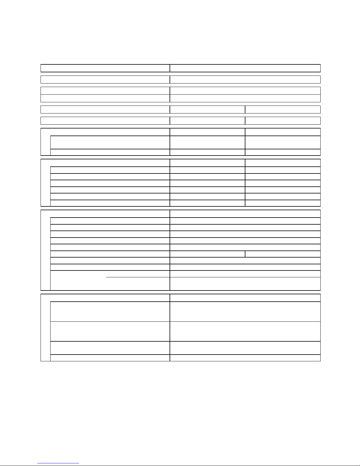
2. SPECIFICATIONS
2-1. Unit Specifications
Outdoor Unit SAP–CMRV3143GJ
Type 4-room multi outdoor unit
Number of connectable indoor units 4
Maximum capacity of connected indoor u
kW 15.4
Maximum capacity of operating indoor units kW 15.4
Power Source 220–240V ~ 50Hz 220V ~ 60Hz
Voltage rating 230 V 220 V
Performance Cooling Cooling
Capacity kW 9.0 (1.2 - 10.5) 9.0 (1.2 - 10.5)
BTU/h 30,700 30,700
Air circulation (High)
m3/h
2,800 2,800
Electrical Rating Cooling Cooling
Available voltage range V 198 ~ 264 198 ~ 242
Running amperes A 8.8 (Max.15.5) 8.8 (Max.15.5)
Power input W 1,940 1,940
Power factor % 96 96
C.O.P. W/W 4.64 4.64
Starting amperes A 12.7 12.7
Features
Controls Microprocessor
Fan speeds Auto (Hi, Lo)
Compressor Twin Rotary (DC inverter)
Refrigerant / Amount charged at shipment g R410A / 4,000
Refrigerant control Electric Expansion Valve
Operation sound Hi dB-A 53 53
Refrigerant tubing connections Flare type
Max. allowable tubing length per unit m 30
Refrigerant Narrow tube mm (in.)
6.35(1/4) × 4
tube diameter Wide tube mm (in.)
9.52(3/8) × 3
mm (in.)
12.7(1/2) × 1
Dimensions & Weight
Unit dimensions Height mm 880
Width mm 940
Depth mm 340
Package dimensions Height mm 981
Width mm 1,016
Depth mm 440
Weight Net kg 90
Shipping kg 92
Shipping volume
m
3
0.439
DATA SUBJECT TO CHANGE WITHOUT NOTICE.
2. Rating conditions are:
Cooling : Indoor air temperature 27°C D.B. / 19° C W.B.
Outdoor air temperature 35°C D.B. / 24°C W.B.
Remarks:
1. The value shown in performance section and electrical rating section above are based on the following unit
combination. For other combination of indoor units, please refer to the "Unit Combination Table" in this manual.
Indoor unts: SAP-KMRV93GJ 4 units
(Outdoor unit: SAP-CMRV3143GJ 1 unit )
3
2-2. Major Component Specifications
2-2-1. Outdoor Unit
Outdoor Unit SAP–CMRV3143GJ
DATA SUBJECT TO CHANGE WITHOUT NOTICE.
Control PCB / HIC PCB / Filter PCB POW-CM5A1-C-T / CR-HIC50A2-C-T / POW-CM5B1-C-T
Compressor
Type DC Twin Rotary (Hermetic)
Compressor model C-9RVN273H0W 80867080
Compressor oil … Amount cc FVC68S … 1900
Coil resistance (Ambient temp. 25°C) Ω R – S: 0.169
S – T: 0.169
T – R: 0.169
Safety devices
CT (Peak current cut-off control) YES
Compressor discharge temp. control YES
Operation cut-off control in abnormal ambient temp. —
Run capacitor µF —
VAC —
Crankcase heater —
Fan & Fan Motor
Type Propeller
Q’ty … Dia. mm 1 … ø460
Fan motor model … Q’ty KFC6S-61C3PA-C … 1
No. of poles … rpm (220V, High) 6 … 712
Nominal output W 60
Coil resistance (Ambient temp. 20°C) Ω BRN – WHT: 66.53
WHT – YEL: 33.95
YEL – PNK: 12.50
Safety devices Type Thermal protector
Operating temp. Open °C 130 ± 8
Close °C 79 ± 15
Run capacitor µF 5
VAC 440
Heat Exchanger Coil
Coil Aluminum plate fin / Copper tube
Rows 2
Fin pitch mm 1.4
Face area m
2
0.630
External Finish Acrylic baked-on enamel finish
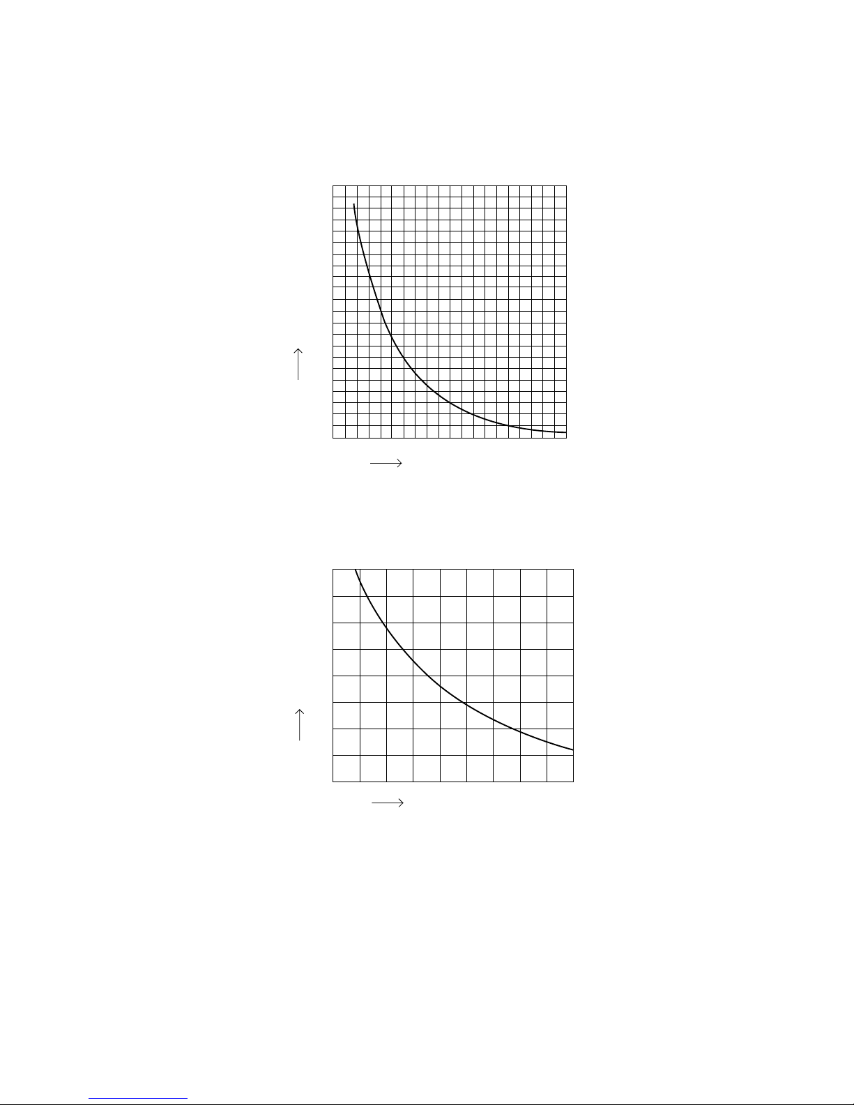
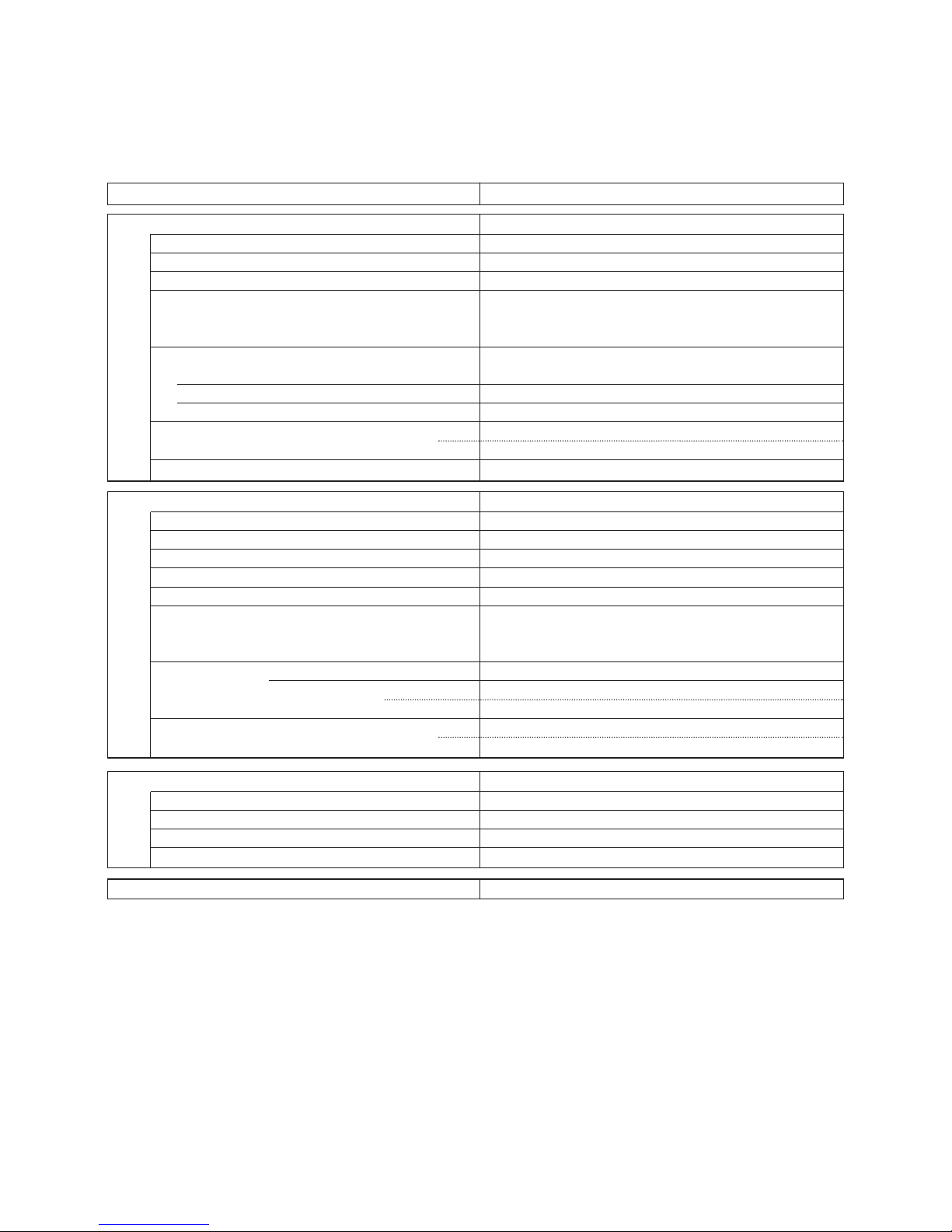
2-3. Other Component Specifications
4
Outdoor Unit SAP–CMRV3143GJ
0
0 102030405060708090
40
60
80
100
120
140
160
180
200
20
Temperature (°C)
• Compressor temp sensor
• Outdoor air temp sensor
• Narrow tube sensor
• Wide tube sensor
40
35
30
25
20
15
10
5
0
|20|15|10|
50 5 101520
Temperature (°C)
Resistance (Ω)
Resistance (Ω)
5
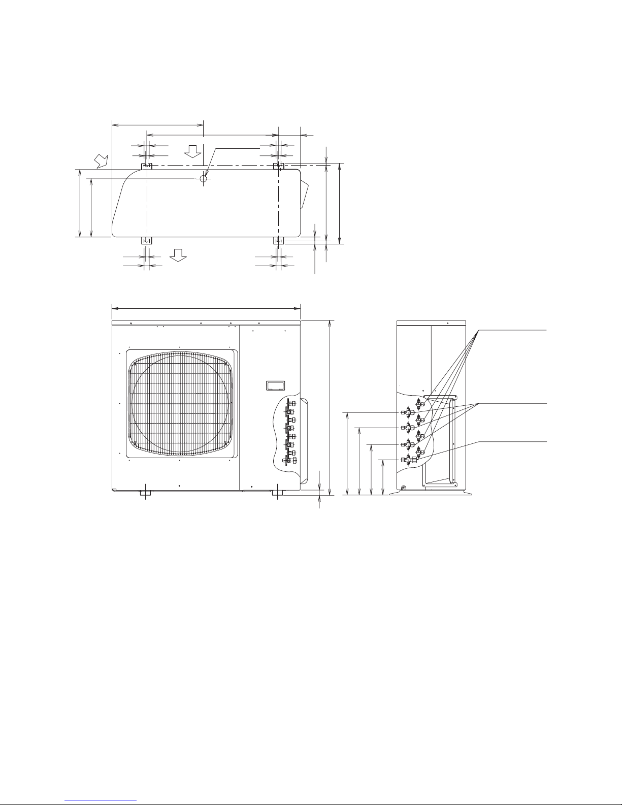
3. DIMENSIONAL DATA
Outdoor Unit SAP–CMRV3143GJ
18
880
940
33.7
Wide tube service
valve ø9.52 (3/8")
Wide tube service
valve ø12.7 (1/2")
Narrow tube service
valve ø6.35 (1/4")
336
256
416
176
25
13
380
AIR DISCHARGE
25
13
465 Unit: mm
25
25
10
405
1313
660
109
Drain hole
AIR INTAKE
296
340
AIR INTAKE
15
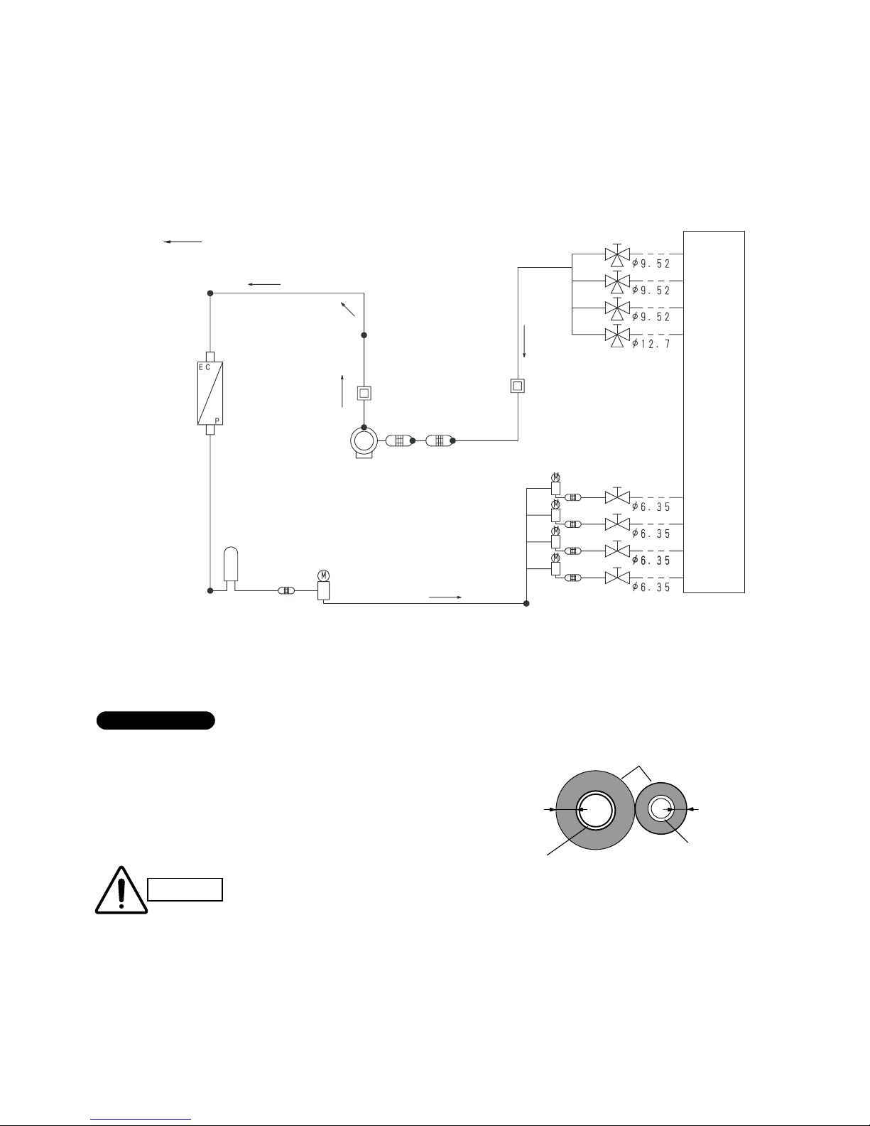
4. REFRIGERANT FLOW DIAGRAM
6
Outdoor Unit SAP–CMRV3143GJ
4-Room Multi-Refrigerant Tubing System Diagram
Unit: mm
Service valve on
wide tube side
Service valve on
narrow tube side
Strainer
Electric expansion
valve
Electric
expansion
valve
Receiver tank
Indoor unit
When cooling
Outdoor heat
exchanger
Main accumulator
Compressor
Muffler
Muffler
Sub-accumulator
Insulation of Refrigerant Tubing
Because capillary tubing is used in the outdoor unit, both the
wide and narrow tubes of this air conditioner become cold. To
prevent heat loss and wet floors due to dripping of
condensation, both tubes must be well insulated with a
proper insulation material. The thickness of the insulation
should be a min. 8 mm.
After a tube has been insulated,
never try to bend it into a narrow
curve because it can cause the tube
to break or crack.
IMPORTANT
CAUTION
Wide tube
Thickness:
Min. 8 mm
Insulation
Narrow tube
Thickness:
Min. 8 mm
7
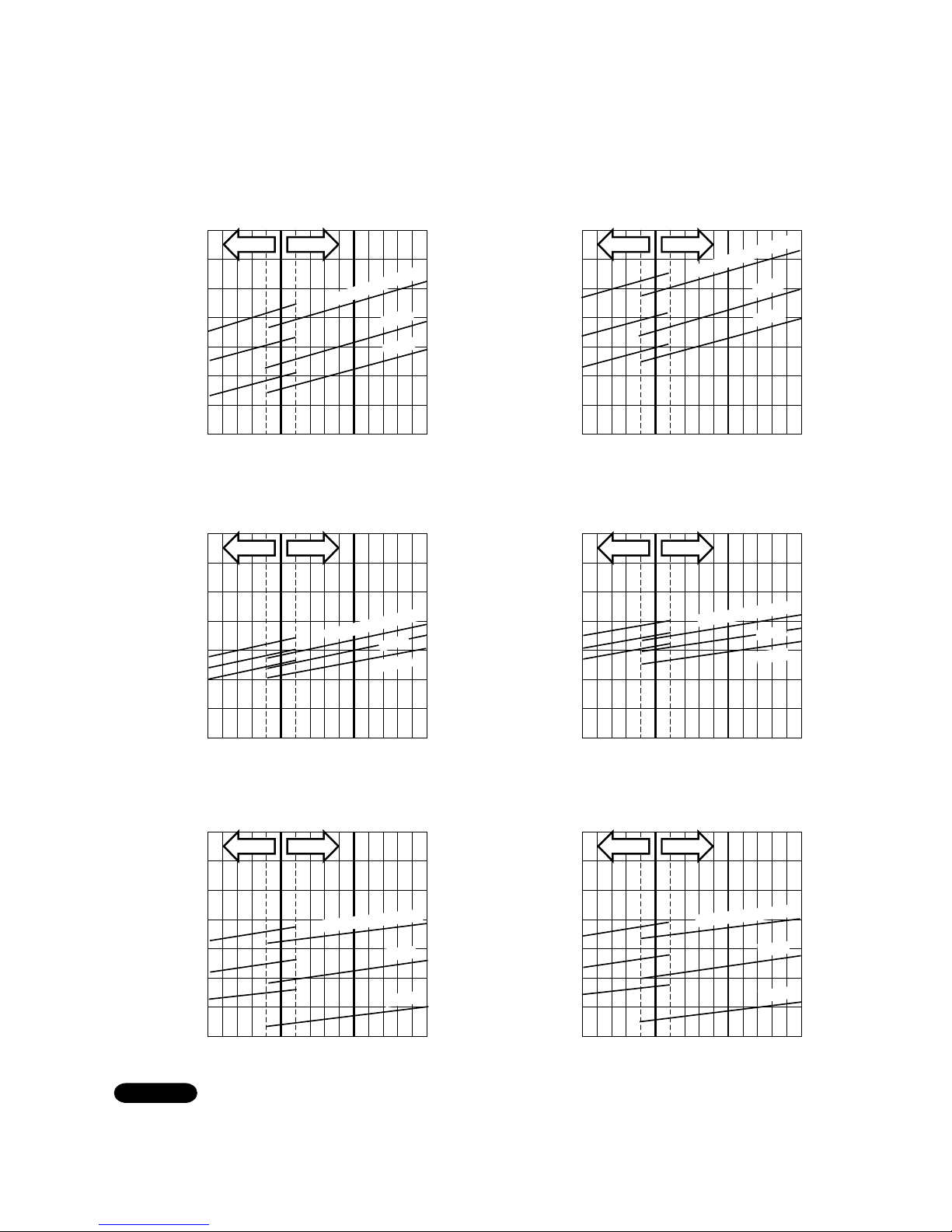
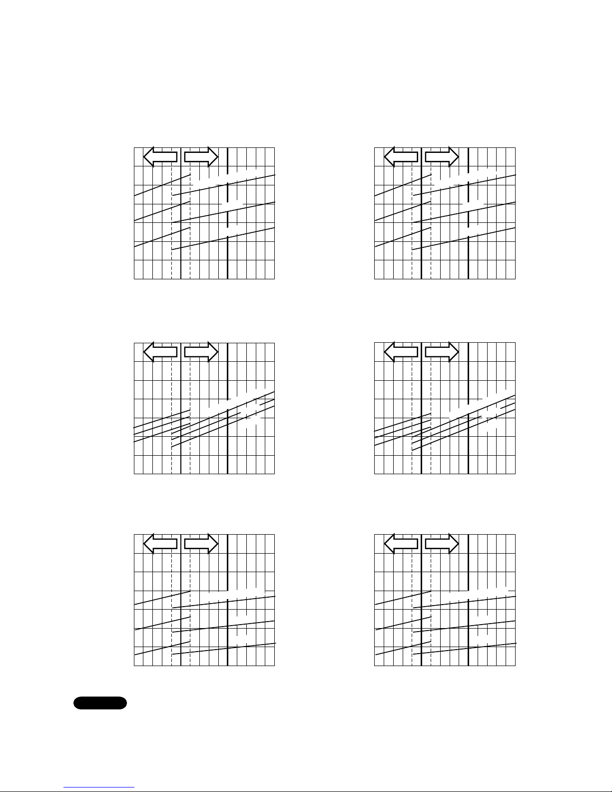
5. PERFORMANCE DATA
5-1. Performance charts
25
8
7
6
5
30 35 40
25
20
18
16
14
12
10
30 35 40
25 30 35 40
1.3
1.2
1.1
1.0
27
°C
24°C
Indoor air temp.30°C
Indoor air temp.30°C
27
°C
24°C
Indoor air temp.30°C
27
°C
24°C
Lo fan Hi fan
Lo fan Hi fan
Lo fan Hi fan
• Cooling Characteristics
(1) Low pressure performance chart
(RH: 46%, Indoor fan speed: High fan)
(2) Operating current performance chart
(RH: 46%, Indoor fan speed: High fan)
(50/60Hz, 220V)
(50/60Hz, 220V)
(3) Indoor discharge air performance chart
(RH: 46%, Indoor fan speed: High fan)
(50/60Hz, 220V)
Operating current (A) Low pressure (MPa)
Indoor discharge air temperature (°C)
Outdoor air temperature (°C)
Outdoor air temperature (°C)
Outdoor air temperature (°C)
Outdoor Unit SAP–CMRV3143GJ
Indoor Unit SAP–KMRV93GJ ××1
25
8
7
6
5
30 35 40
25
20
18
16
14
12
10
30 35 40
25 30 35 40
1.2
1.1
1.0
0.9
27
°C
24°C
Indoor air temp.30°C
Indoor air temp.30°C
27
°C
24°C
Indoor air temp.30°C
27
°C
24°C
Lo fan Hi fan
Lo fan Hi fan
Lo fan Hi fan
• Cooling Characteristics
(1) Low pressure performance chart
(RH: 46%, Indoor fan speed: High fan)
(2) Operating current performance chart
(RH: 46%, Indoor fan speed: High fan)
(50/60Hz, 220V)
(50/60Hz, 220V)
(3) Indoor discharge air performance chart
(RH: 46%, Indoor fan speed: High fan)
(50/60Hz, 220V)
Operating current (A) Low pressure (MPa)
Indoor discharge air temperature (°C)
Outdoor air temperature (°C)
Outdoor air temperature (°C)
Outdoor air temperature (°C)
Outdoor Unit SAP–CMRV3143GJ
Indoor Unit SAP–KMRV123GJ ××1
NOTE
• This performance chart shows operation of a single wall-mounted indoor unit. The performance chart will vary depending on the indoor unit type.
• Check each performance value in test-run mode. Electrical performance values represent a combined indoor/outdoor value.(In this case, be sure to
stop all the indoor units where performance is not being checked.)
• The performance is for a tubing length of 7.5 m. If the tubing length is different, the performance chart will vary.
8
25
10
9
8
7
30 35 40
25
10
12
14
16
18
20
30 35 40
25
1.2
1.1
1.0
0.9
30 35 40
27
°C
24°C
24°C
Indoor air temp.30°C
Indoor air temp.30°C
27
°C
27
°C
Indoor air temp.30°C
24°C
Lo fan Hi fan
Lo fan Hi fan
Lo fan Hi fan
• Cooling Characteristics
(1) Low pressure performance chart
(RH: 46%, Indoor fan speed: High fan)
(2) Operating current performance chart
(RH: 46%, Indoor fan speed: High fan)
(50/60Hz, 220V)
(50/60Hz, 220V)
(3) Indoor discharge air performance chart
(RH: 46%, Indoor fan speed: High fan)
(50/60Hz, 220V)
Operating current (A) Low pressure (MPa)
Indoor discharge air temperature (°C)
Outdoor air temperature (°C)
Outdoor air temperature (°C)
Outdoor air temperature (°C)
Outdoor Unit SAP–CMRV3143GJ
Indoor Unit SAP–KMRV183GJ ××1
25
10
12
14
16
18
20
30 35 40
25
1.2
1.1
1.0
0.9
30 35 40
27
°C
24°C
Indoor air temp.30°C
27
°C
Indoor air temp.30°C
24°C
Lo fan Hi fan
Lo fan Hi fan
• Cooling Characteristics
(1) Low pressure performance chart
(RH: 46%, Indoor fan speed: High fan)
(2) Operating current performance chart
(RH: 46%, Indoor fan speed: High fan)
(50/60Hz, 220V)
(3) Indoor discharge air performance chart
(RH: 46%, Indoor fan speed: High fan)
(50/60Hz, 220V)
Low pressure (MPa)
Indoor discharge air temperature (°C)
Outdoor air temperature (°C)
Outdoor air temperature (°C)
25 30 35 40
11
10
9
8
24°C
Indoor air temp.30°C
27
°C
Lo fan Hi fan
(50/60Hz, 220V)
Operating current (A)
Outdoor air temperature (°C)
Outdoor Unit SAP–CMRV3143GJ
Indoor Unit SAP–KMRV243GJ ××1
NOTE
• This performance chart shows operation of a single wall-mounted indoor unit. The performance chart will vary depending on the indoor unit type.
• Check each performance value in test-run mode. Electrical performance values represent a combined indoor/outdoor value.(In this case, be sure to
stop all the indoor units where performance is not being checked.)
• The performance is for a tubing length of 7.5 m. If the tubing length is different, the performance chart will vary.
9
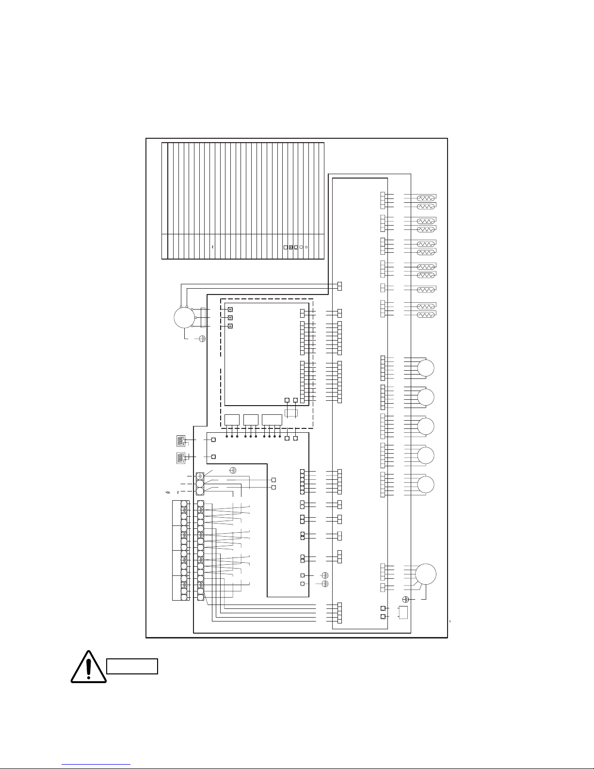
6. ELECTRICAL DATA
6-1. Electric Wiring Diagram
Outdoor Unit SAP–CMRV3143GJ
CAUTION
WHT
YEL
YEL
YEL
YEL
YEL
YEL
BLK
WHT
BLK
BLK
BLK
BLK
BLK
BLK
BLK
YEL
YEL
WHT
BLK
BLK
BLK
BLK
BLK
BLK
BLK
BLK
BLK
WHT
BLK
BLK
BLK
BLK
BLK
BLK
BLK
BLK
BLK
WHT
BLK
YEL
PNK
WHT
YEL
BLU
WHT
WHT
(WHT)
PRY
(WHT)
CT
L1 L2
(WHT)
PAM
WHT
WHT
BLK
BLK
BLK
BLK
BLK
BLK
BLK
BLK
BLK
RED
WHT
FERRITE CORE
WHT
WHT
THERMISTOR(ROOM D WIDE PIPE)
THERMISTOR(ROOM D NARROW PIPE)
THERMISTOR(ROOM C NARROW PIPE)
THERMISTOR(ROOM C WIDE PIPE)
WHT
RED
U V W
GRN/YEL
BLU
EARTH
UNIT D
INDOOR
UNIT C
INDOOR
UNIT B
INDOOR
WHT
GRN/YEL GRN/YEL GRN/YEL GRN/YEL
GRN/YEL
WHT
BLK
BLK
BLK
BLK
BLK
BASE(16P)
TERMINAL
TRANSISTOR
DIODE
BRIDGE DIODE
MECHANICAL VALVE
THERMISTOR(ROOM B NARROW PIPE)
THERMISTOR(ROOM B WIDE PIPE)
CONTROL PCB
UNIT A
INDOOR
YEL
GRY
WHT
BLK
BLK
BLK
BLK
BLK
BLK
BLK
BLK
BLK
BLK
FILTER PCB
HS
CM
ORG
31 5 7 9
BRN
TERMINAL BASE(3P)
1
AC220V
240V
AC200-L2
TH11
TH10
BLK
YEL
YEL
BLK
4321
TH9
TH8
YEL
YEL
YEL
4321
TH7
TH6
YEL
YEL
YEL
4321
TH5
TH4
TH2
TH1
WHT
6
ORG
BLU
BRN
YEL
RED
1 54326
1 2 3 4 1 2 1 2 1 33 45 6 7 8 9
10
7 8
1110
RED
BLU
ORG
WHT
YEL
BRN
1
C0
3
GRY
+
MC01
MC02
ORG
GRY
6
TH3
1
31 21 54 7621
31 21 54 7621
WHT
HIC PCB
YEL
BLU
BRN
YEL
YEL
RED
WHT
YEL
YEL
+
54321
CN37
MVA
MVAMMV MVB MVC MVD
BRN
RED
YEL
ORG
BLU
6
WHT
(BLK)
BRN
WHT
RE1 RE2
RE1 RE2
D
TR
BD
6
ORG
RED
4
FMO
321
YEL
BLU
WHT
BRN
GRY
GRN/YEL
BLK
1 3 1 5 73 1 2 3 4 5 1 2 3 4 1 2
GRY
WHT
31 5
AC200-L1G1 G2
DC280-
DC280+
1 2 3 4 55432
SOLDERED TERMINAL
TERMINAL
TERMINAL BASE
CONNECTOR
THERMISTOR(ROOM A WIDE PIPE)
THERMISTOR(ROOM A NARROW PIPE)
THERMISTOR(COMPRESSOR TEMP)
THERMISTOR(OUTDOOR TEMP)
THERMISTOR(HEAT EXCHANGER)
BOARD-IN-WIRE
HEAT SINK
REACTOR
MAIN MOTOR OPERATED VALVE
FAN MOTOR
COMPRESSOR MOTOR
OPERATION CONDENSER
TH3
TH4
TH5
TH6
TH7
TH8
TH9
TH10
TH11
TH2
TH1
BDCMC0DFC1
,
2
FM0HSMMV
MVA MVD
RE1
,
2
TR
DESCRIPTION
SYMBOLS
ELECTRIC WIRING DIAGRAM
1 2 3 4 1 2 1 23 45 6 7 8 9
10
7 8
1110
49C
CN31
(BLU)
HIC3
CN18
(WHT)
HIC2
CN30
(WHT)
(WHT)
CN02
HIC2
(WHT)
CN03
HIC3
(WHT)
CN01
HIC1
HIC
+
HIC
-
FC2
HIC
+
HIC
-
HIC1
CN34
(WHT)
PAM
CN23
(WHT)
CT
CN08
(WHT)
PRY
CN21
(RED)
DC280
CN01
(WHT)
AC200
CN29
(RED)
SI
CN35
(WHT)
(RED)
CN38
MNB
(WHT)
CN36
MMV
(WHT)
CN09
FM0
(WHT)
CN16
FM0TH
(BLU)
CN39
MVC
(YEL)
CN40
MVD
(EHT)
CN13
COIL/GAIKI
(BLK)
CN19
COMP
(BLK)
CN24
ATH
(RED)
CN22
BTH
(BLU)
CN20
CTH
(YEL)
CN25
DTH
+
+
W
W
W
1 2 4 1 2 4 1 2 4 1 2
1 2
4
1 2 31 2 31 2 31 2 3
++
GRN/YEL
GRN/YEL
WWWWW
WW
W
854-2-5269-182-00-2
MULTIPLE INDOOR UNITS
COOLING ONLY OUTDOOR UNIT FOR FOUR-ROOM
Electric Wiring Diagram for 4-room multi outdoor unit (CMRV3143GJ)
Before replacing PCBs, turn off the power and check that all
lamps on the PCB are off before starting work. Electric shock
will occur if work is performed while the lamps are lit.
Electric Shock
 Loading...